EP2508056A1 - Ablage- und Haltevorrichtung für abgekoppelte Leitungen für mobile Arbeitsmaschinen und auswechselbare Ausrüstungen - Google Patents
Ablage- und Haltevorrichtung für abgekoppelte Leitungen für mobile Arbeitsmaschinen und auswechselbare Ausrüstungen Download PDFInfo
- Publication number
- EP2508056A1 EP2508056A1 EP12158570A EP12158570A EP2508056A1 EP 2508056 A1 EP2508056 A1 EP 2508056A1 EP 12158570 A EP12158570 A EP 12158570A EP 12158570 A EP12158570 A EP 12158570A EP 2508056 A1 EP2508056 A1 EP 2508056A1
- Authority
- EP
- European Patent Office
- Prior art keywords
- storage
- holding device
- holding
- coupling
- holding element
- Prior art date
- Legal status (The legal status is an assumption and is not a legal conclusion. Google has not performed a legal analysis and makes no representation as to the accuracy of the status listed.)
- Granted
Links
Images




Classifications
-
- B—PERFORMING OPERATIONS; TRANSPORTING
- B60—VEHICLES IN GENERAL
- B60D—VEHICLE CONNECTIONS
- B60D1/00—Traction couplings; Hitches; Draw-gear; Towing devices
- B60D1/58—Auxiliary devices
- B60D1/60—Covers, caps or guards, e.g. comprising anti-theft devices
-
- A—HUMAN NECESSITIES
- A01—AGRICULTURE; FORESTRY; ANIMAL HUSBANDRY; HUNTING; TRAPPING; FISHING
- A01B—SOIL WORKING IN AGRICULTURE OR FORESTRY; PARTS, DETAILS, OR ACCESSORIES OF AGRICULTURAL MACHINES OR IMPLEMENTS, IN GENERAL
- A01B59/00—Devices specially adapted for connection between animals or tractors and agricultural machines or implements
-
- B—PERFORMING OPERATIONS; TRANSPORTING
- B60—VEHICLES IN GENERAL
- B60D—VEHICLE CONNECTIONS
- B60D1/00—Traction couplings; Hitches; Draw-gear; Towing devices
- B60D1/58—Auxiliary devices
- B60D1/62—Auxiliary devices involving supply lines, electric circuits or the like
Definitions
- the invention relates to a storage and holding device for uncoupled fluid lines for mobile machines and interchangeable equipment according to the preamble of claim 1.
- the tractor dominates as a transport vehicle, but at the same time as a drive unit for attached or towed interchangeable equipment.
- Tractors and interchangeable equipment such as mowers, turneries, rakes, balers, coupled and cooperatively provide a mobile working machine for agricultural use.
- the tractor has interfaces for energy transmission to the interchangeable equipment, such as the PTO, the electrical socket or the hydraulic taps for coupling hydraulic drive elements.
- These hydraulic taps are usually tractor-side designed as a fixedly mounted coupling sleeves and the counterpart as a coupling element are the coupling plug, which are attached to the end of hydraulic hoses.
- the hydraulic hoses must also be disconnected and stored.
- the invention relates to a storage and holding device for flexible and uncoupled lines of the electrical, hydraulic or pneumatic and it has the advantage that the holding elements regardless of the nominal diameter of a line, whether as power and / or signal line or hose line fulfill their function. But regardless of this, the solution offers considerably so-called Händlingvormaschine, since the coupling elements must be inserted into any connector.
- the holding device is based on the effect of the magnetic force of a permanent magnet.
- the coupling elements of lines are formed either as a coupling plug or coupling sleeves and made of ferromagnetic material, so that they enter into a non-positive connection with the permanent magnet as a holding element.
- the holding element and thus the permanent magnet is received by a hinge connection, so that the. Permanent magnet of the current position and orientation of the coupling element when placing the line on this zuschnappend adapt.
- the storage and holding device may comprise a plurality of holding elements arranged in a row, so that they can accommodate a plurality of lines, even different nominal diameters, regardless of whether these coupling plug or coupling sleeves have at their ends.
- the retaining elements in a holder and in a preferred Design of an open housing with a through hole, arranged so that they are protected from external undesirable effects.
- This storage and holding device according to the invention can be part of a machine or an exchangeable device in the field of agricultural technology, but also in the field of municipal technology or in the field of construction machinery technology and is not limited even to these areas.
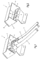
- Fig.1 shows a perspective view of the storage and holding device 1 with uncoupled or stored and held lines 6,7,8 or hydraulic hose lines 6,7,8 and Fig.2 shows analog Fig.1 also in a perspective view of the storage and holding device 1 but without the lines or hydraulic hose lines.
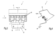
- Figure 3 shows the front view of the storage and holding device 1 and Figure 4 the side view of the storage and holding device 1 according to Fig. 3 seen in the direction of Y
- the storage and holding device 1 consists essentially of a housing 2 and at least one holding element 3 with a permanent magnet 4.
- the illustrated embodiment has a total of three holding elements 3, wherein the number of holding elements 3 is not limited to three.
- the Retaining elements 3 are fastened by means of screw connections to the rear wall 9 of the housing.
- the housing 2 has a passage opening 5, through which the free ends of the uncoupled hydraulic hose lines 6,7,8 can be passed.
- the hose lines 6, 7 are end-sided with a coupling plug 10, 11, and the hose line 8 is end-equipped with a coupling sleeve 12.
- the hose 6 should have a smaller nominal diameter than the remaining hose lines 7 and 8.
- the size of the coupling plug 10 is a smaller than that of the coupling plug 11, wherein in the embodiment of the coupling plug 11 and the coupling sleeve 12 should belong to the same size.
- the housing 2 further comprises the side walls 14,14 ', the roof cover 13 and a flange 15 with the through holes 16.
- the latter serve to firmly screw the entire storage and holding device 1 to a machine or a device.
- the through hole 5 of the storage and holding device 1 is mainly facing the ground, so that when storing the machines or devices outdoors the coupling plug 10,11 or coupling sleeve 12th are not exposed to direct contact with rainwater. This position of use is for example in the Fig. 3 and Fig.4 shown.
- a holding element 3 further consists in detail of a socket element 17 for receiving the permanent magnet 4 and a flange 18 for screwing to the rear wall 9 of the housing 2 by means of a screw 20th
- Figure 5 shows the section AA according to Figure 3 with stretched holding element and Figure 6 shows the section AA according to Figure 3 but with angled holding element.
- the holding element 3 consists essentially of the socket element 17 which receives the permanent magnet 4 in a fixed connection with this, the hinge flange 22, the flange member 18 and the hinge 19 with its hinge axis 23.
- the permanent magnet 4 is preferably designed as a round magnet and he finds its seat in the formed as a round part socket member 17 which has a screw 21 at the end, with which the socket member 17 is screwed to the hinge flange 22.
- the socket member 17 is connected to the flange member 18 in the hinge joint 19 formed as a hinge.
- the flange member 18 is bolted to the screw connection 20 with the rear wall 9 of the housing 2.
- the articulated part of the Retaining element 3, consisting of the socket element 17, the permanent magnet 4 and the hinge flange 22, a pivoting movement with a pivot angle ⁇ , as in the Fig. 6a shown to perform the hinge axis 23. 5a however, the extended position of the hinge connection with the angle ⁇ zero angle degree.
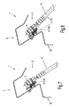
- Figure 10 shows analog Fig. 8 the same situation, but with angled support member 3 with a pivot angle ⁇ greater than zero angular degree.
- Figure 12 shows analog Fig. 10 the same situation, but with angled support member 3 with a pivot angle ⁇ greater than zero angular degree.
Landscapes
- Engineering & Computer Science (AREA)
- Life Sciences & Earth Sciences (AREA)
- Mechanical Engineering (AREA)
- Transportation (AREA)
- Zoology (AREA)
- Soil Sciences (AREA)
- Environmental Sciences (AREA)
- Supports For Pipes And Cables (AREA)
- Agricultural Machines (AREA)
Abstract
Description
- Die Erfindung betrifft eine Ablage- und Haltevorrichtung für abgekoppelte Fluidleitungen für mobile Arbeitsmaschinen und auswechselbare Ausrüstungen gemäß dem Oberbegriff des Anspruches 1.
- In der Landtechnik beispielsweise dominiert der Traktor als Transportfahrzeug, aber auch zugleich als Antriebseinheit für angebaute oder gezogene auswechselbare Ausrüstungen. Traktor und auswechselbare Ausrüstung, wie beispielsweise Mähwerke, Wender, Schwader, Ballenpressen, ergeben gekoppelt und zusammenwirkend eine mobile Arbeitsmaschine für den landtechnischen Einsatz. Der Traktor verfügt über Schnittstellen zur Energieübertragung an die auswechselbare Ausrüstung, wie beispielsweise die Zapfwelle, die elektrische Steckdose oder auch die hydraulischen Zapfstellen zur Ankopplung hydraulischer Antriebselemente. Diese hydraulischen Zapfstellen sind im Regelfall traktorseitig als ortsfest angebrachte Kupplungsmuffen ausgebildet und das Gegenstück als Kupplungselement sind die Kupplungsstecker, die endseitig an Hydraulikschläuchen angebracht sind.
- Werden die auswechselbaren Ausrüstungen vom Traktor abgekoppelt und geparkt, so müssen die Hydraulikschläuche ebenfalls abgekoppelt und abgelegt werden. Dazu existieren Ablagevorrichtungen in Form sogenannter Blindkupplungsmuffen. Damit die Kupplungsstecker der Hydraulikschläuche nicht verschmutzen gibt es sogenannte Blindkupplungsmuffen, die an den auswechselbaren Ausrüstungen, d.h. geräteseitig, angebracht sind und in die die Kupplungsstecker eingeführt und von diesen während des Parkens gehalten werden. Da die Kupplungsstecker in ihren Abmessungen je Durchflussmenge des Hydrauliköls baugrößenabhängig variieren müssen auch die Blindstecker oder sonstige Haltevorrichtungen entsprechend der Baugröße den Kupplungssteckern angepasst sein.
- Hier setzt die Aufgabe der Erfindung an mit dem Ziel, eine verbesserte, leicht zu handhabende, verschmutzungssichere Ablagevorrichtung für abgekoppelte Leitungen, insbesondere Hydraulikschlauchleitungen, vorzuschlagen.
- Gelöst wird die Aufgabe der Erfindung mit den kennzeichnenden Merkmalen des unabhängigen Anspruchs 1. Weitere vorteilhafte Ausgestaltungen der Erfindung sind den abhängigen Ansprüchen, der Beschreibung und den Figurendarstellungen zu entnehmen.
- Die Erfindung betrifft eine Ablage- und Haltevorrichtung für flexible und abgekoppelte Leitungen der Elektrik, Hydraulik oder Pneumatik und sie beinhaltet den Vorteil, dass die Halteelemente unabhängig vom Nenndurchmesser einer Leitung, ob als Strom- und/oder Signalleitung oder als Schlauchleitung ihre Funktion erfüllen. Aber unabhängig davon bietet die Lösung erheblich sogenannte Händlingsvorteile, da die Kupplungselemente in keine Steckverbindung eingeführt werden müssen.
- Die Haltevorrichtung basiert auf der Wirkung der magnetischen Kraft eines Dauermagneten. Die Kupplungselemente von Leitungen sind entweder als Kupplungsstecker oder Kupplungsmuffen und aus ferromagnetischem Werkstoff ausgebildet, so dass diese mit dem Dauermagneten als Halteelement eine kraftschlüssige Verbindung eingehen. In besonders vorteilhafter Weise ist das Halteelement und damit der Dauermagnet von einer Gelenkverbindung aufgenommen, so dass sich der. Dauermagnet der momentanen Lage und Ausrichtung des Kupplungselements beim Ablegen der Leitung auf diesen zuschnappend anpassen kann. Dadurch stellt sich momentan zumindest ein linienförmiger Kontakt zwischen dem Dauermagneten und dem Kupplungselement ein, der bereits eine hinreichende Haltekraft zwischen diesen beiden Elementen sicherstellt.
- In einer weiteren Ausgestaltung der Erfindung kann die Ablage- und Haltevorrichtung mehrere in einer Reihe angeordnete Halteelemente umfassen, so dass diese mehrere Leitungen, auch unterschiedlicher Nenndurchmesser, unabhängig davon, ob diese Kupplungsstecker oder Kupplungsmuffen an ihren Enden aufweisen, aufnehmen kann.
- Um die Kupplungsstecker oder Kupplungsmuffen im abgelegten Zustand vor Beschädigungen durch äußere Einflüsse, wie Verschmutzung oder Regenwasser, zu schützen, sind die Halteelemente in einer Halterung und in einer bevorzugten Ausgestaltung einem offenen Gehäuse mit einer Durchgangsöffnung, angeordnet, so dass diese vor äußeren unerwünschten Einwirkungen geschützt sind.
- Diese erfindungsgemäße Ablage- und Haltevorrichtung kann Teil einer Maschine oder einer auswechselbaren Einrichtung im Bereich der Landtechnik, aber auch im Bereich der Kommunaltechnik oder im Bereich der Baumaschinentechnik sein und ist selbst auf diese Bereiche nicht eingeschränkt.
- Anhand der Figurendarstellungen
Fig.1 bis Fig.12 ist die Erfindung beispielhaft dargestellt und erläutert. - Es zeigen:
- Fig.1
- perspektivische Darstellung der Ablage- und Haltevorrichtung mit abgekoppelten bzw. abgelegten Leitungen
- Fig.2
- perspektivische Darstellung der Ablage- und Haltevorrichtung analog
Fig. 1 aber ohne abgekoppelte bzw. abgelegte Leitungen - Fig.3
- Vorderansicht der Ablage- und Haltevorrichtung
- Fig.4
- Seitenansicht der Ablage- und Haltevorrichtung
- Fig.5
- Schnitt A-A gemäß
Fig.3 mit gestrecktem Halteelement - Fig.5a
- einen vergrößerten Ausschnitt aus
Fig.5 - Fig.6
- Schnitt A-A gemäß
Fig.3 mit abgewinkeltem Halteelement - Fig.6a
- einen vergrößerten Ausschnitt aus
Fig.6 - Fig.7
- Schnitt A-A gemäß
Fig.3 mit gestrecktem Halteelement und abgelegter Hydraulikschlauchleitung mit Kupplungsstecker - Fig.8
- Schnitt A-A gemäß
Fig.3 mit abgewinkeltem Halteelement und abgelegter Hydraulikschlauchleitung mit Kupplungsstecker - Fig.9
- Schnitt A-A gemäß
Fig.3 mit gestrecktem Halteelement und abgelegter Hydraulikschlauchleitung mit Kupplungsstecker mit größerem Nenndurchmesser als inFig. 7 dargestellt - Fig.10
- Schnitt A-A gemäß
Fig.9 mit abgewinkeltem Halteelement und abgelegter Hydraulikschlauchleitung mit Kupplungsstecker - Fig.11
- Schnitt A-A gemäß
Fig.9 mit gestrecktem Halteelement und abgelegter Hydraulikschlauchleitung mit Kupplungsmuffe - Fig.12
- Schnitt A-A gemäß
Fig.11 mit abgewinkeltem Halteelement und abgelegter Hydraulikschlauchleitung mit Kupplungsmuffe -
Fig.1 zeigt eine perspektivische Darstellung der Ablage- und Haltevorrichtung 1 mit abgekoppelten bzw. abgelegten und gehaltenen Leitungen 6,7,8 bzw. hydraulischen Schlauchleitungen 6,7,8 undFig.2 zeigt analogFig.1 ebenfalls in einer perspektivischen Darstellung die Ablage- und Haltevorrichtung 1 aber ohne die Leitungen bzw. hydraulischen Schlauchleitungen.Fig.3 zeigt die Vorderansicht der Ablage- und Haltevorrichtung 1 undFig.4 die Seitenansicht der Ablage- und Haltevorrichtung 1 gemäßFig. 3 in Richtung Y gesehen. - Die Ablage- und Haltevorrichtung 1 besteht im Wesentlichen aus einem Gehäuse 2 und wenigstens einem Halteelement 3 mit einem Dauermagneten 4. Das dargestellte Ausführungsbeispiel weist insgesamt drei Halteelemente 3 auf, wobei die Anzahl der Halteelemente 3 keineswegs auf drei beschränkt ist. Die Halteelemente 3 sind mittels Verschraubungen an der Rückwand 9 des Gehäuses befestigt. Das Gehäuse 2 weist eine Durchgangsöffnung 5 auf, durch die die freien Enden der abgekoppelten hydraulischen Schlauchleitungen 6,7,8 hindurchgeführt werden können. In dem Ausführungsbeispiel sind die Schlauchleitungen 6,7 endseitig mit einem Kupplungsstecker 10, 11 und ist die Schlauchleitung 8 endseitig mit einer Kupplungsmuffe 12 ausgestattet. Dabei soll die Schlauchleitung 6 einen kleineren Nenndurchmesser als die übrigen Schlauchleitungen 7 und 8 aufweisen. Das bedeutet, dass die Baugröße des Kupplungssteckers 10 eine kleinere ist als die des Kupplungssteckers 11, wobei in dem Ausführungsbeispiel der Kupplungsstecker 11 und die Kupplungsmuffe 12 der gleichen Baugröße angehören sollen. Diese dargestellten Baugrößenunterschiede sind deshalb von Bedeutung, um klar zu stellen, dass die Halteelemente nicht nur auf eine bestimmte Baugröße ausgelegt sind und dass diese gleichermaßen Kupplungsstecker 10,11 wie Kupplungsmuffen 12 kraftschlüssig durch die magnetische Haltekraft der Dauermagneten 4 aufnehmen können.
- Das Gehäuse 2 weist weiterhin die Seitenwände 14,14', die Dachabdeckung 13 und einen Flansch 15 mit den Durchgangsbohrungen 16 auf. Letztere dienen dazu, die gesamte Ablage- und Haltevorrichtung 1 an einer Maschine oder einem Gerät fest anzuschrauben. In der Praxis ist es sinnvoll, dass die Durchgangsöffnung 5 der Ablage- und Haltevorrichtung 1 überwiegend dem Erdboden zugewandt ist, damit bei der Lagerung der Maschinen oder Vorrichtungen im Freien die Kupplungsstecker 10,11 bzw. Kupplungsmuffe 12 keinem direkten Kontakt mit dem Regenwasser ausgesetzt sind. Diese Gebrauchslage ist beispielsweise in der
Fig. 3 und Fig.4 dargestellt. - Ein Halteelement 3 besteht im Einzelnen weiterhin aus einem Fassungselement 17 zur Aufnahme des Dauermagneten 4 und einem Flanschelement 18 zum Anschrauben an die Rückwand 9 des Gehäuses 2 mittels einer Schraubverbindung 20.
-
Fig.5 zeigt den Schnitt A-A gemäßFig.3 mit gestrecktem Halteelement undFig.6 zeigt den Schnitt A-A gemäßFig.3 jedoch mit abgewinkeltem Halteelement 3. -
Fig.5a zeigt einen vergrößerten Ausschnitt ausFig.5 und Fig.6 einen vergrößerten Ausschnitt ausFig.6a . Beide Figuren zeigen das Halteelement 3, und zwarFig.5a das Halteelement 3 im gestreckten Zustand undFig.6a das Halteelement 3 im abgewinkelten Zustand. Das Halteelement 3 besteht im Wesentlichen aus dem Fassungselement 17, welches den Dauermagnet 4 in einer festen Verbindung mit diesem aufnimmt, dem Scharnierflansch 22, dem Flanschelement 18 und der Gelenkverbindung 19 mit seiner Gelenkachse 23. Der Dauermagnet 4 ist vorzugsweise als Rundmagnet ausgebildet und er findet seinen Sitz in dem als Rundteil ausgebildeten Fassungselement 17, welches endseitig eine Schraubverbindung 21 aufweist, mit der das Fassungselement 17 mit dem Scharnierflansch 22 verschraubt ist. Das Fassungselement 17 ist mit dem Flanschelement 18 in der Gelenkverbindung 19, ausgebildet als Scharnier, verbunden. Das Flanschelement 18 ist mit der Schraubverbindung 20 mit der Rückwand 9 des Gehäuses 2 verschraubt. Somit kann der gelenkige Teil des Halteelements 3, bestehend aus dem Fassungselement 17, dem Dauermagnet 4 und dem Scharnierflansch 22, eine Schwenkbewegung mit einem Schwenkwinkel β, wie in derFig. 6a dargestellt, um die Gelenkachse 23 ausführen.Fig.5a hingegen zeigt die gestreckte Lage der Scharnierverbindung mit dem Winkel β = Null Winkelgrad. -
Fig.7 zeigt analogFig. 5 den Schnitt A-A gemäßFig.3 mit gestrecktem Halteelement 3, d.h. mit dem Winkel β = Null Winkelgrad, ergänzend jedoch mit abgelegter Hydraulikschlauchleitung 6 mit endseitigem Kupplungsstecker 10, abgehängt an dem Dauermagnet 4 undFig.8 zeigt analogFig. 6 die gleiche Situation, jedoch mit abgewinkeltem Halteelement 3 mit einem Schwenkwinkel β größer Null Winkelgrad. -
Fig.9 zeigt analogFig. 7 den Schnitt A-A gemäßFig.3 mit gestrecktem Halteelement 3, d.h. mit dem Winkel β = Null Winkelgrad mit abgelegter Hydraulikschlauchleitung 7 mit größerem Nenndurchmesser als inFig.7 dargestellt und ebenfalls mit endseitigem Kupplungsstecker 11, abgehängt an dem Dauermagnet 4, undFig.10 zeigt analogFig. 8 die gleiche Situation, jedoch mit abgewinkeltem Halteelement 3 mit einem Schwenkwinkel β größer Null Winkelgrad. -
Fig.11 zeigt analogFig. 7 den Schnitt A-A gemäßFig.3 mit gestrecktem Halteelement 3, d.h. mit dem Winkel β = Null Winkelgrad mit abgelegter Hydraulikschlauchleitung 7 mit größerem Nenndurchmesser als inFig.7 dargestellt aber mit endseitiger Kupplungsmuffe 12, abgehängt an dem Dauermagnet 4, und -
Fig.12 zeigt analogFig. 10 die gleiche Situation, jedoch mit abgewinkeltem Halteelement 3 mit einem Schwenkwinkel β größer Null Winkelgrad. -
- 1
- Ablage- und Haltevorrichtung
- 2
- Halterung, Gehäuse
- 3
- Halteelement
- 4
- Dauermagnet
- 5
- Durchgangsöffnung
- 6
- flexible Leitung, Schlauchleitung
- 7
- flexible Leitung, Schlauchleitung
- 8
- flexible Leitung, Schlauchleitung
- 9
- Rückwand
- 10
- Kupplungselement, Kupplungsstecker
- 11
- Kupplungselement, Kupplungsstecker
- 12
- Kupplungselement, Kupplungsmuffe
- 13
- Dachabdeckung
- 14,14'
- Seitenwand
- 15
- Flansch
- 16
- Durchgangsbohrung
- 17
- Fassungselement
- 18
- Flanschelement, Befestigungsflansch
- 19
- Gelenkverbindung
- 20
- Schraubverbindung
- 21
- Schraubverbindung
- 22
- Scharnierflansch
- 23
- Gelenkachse
- β
- Schwenkwinkel
Claims (10)
- Ablage- und Haltevorrichtung (1) für flexible und abgekoppelte Leitungen der Elektrik, Hydraulik oder Pneumatik mit endseitig angebrachten Kupplungselementen und insbesondere Kupplungssteckern oder Kupplungsmuffen, dadurch gekennzeichnet, dass die Ablage- und Haltevorrichtung (1) wenigstens ein Halteelement (3) mit einem Dauermagneten (4) zur Halterung einer abgekoppelten Leitung (6,7,8) aufweist.
- Ablage- und Haltevorrichtung nach Anspruch 1, dadurch gekennzeichnet, dass das Halteelement (3) eine Gelenkverbindung (19) aufweist.
- Ablage- und Haltevorrichtung nach Anspruch 1, dadurch gekennzeichnet, dass das Halteelement (3) einen Befestigungsflansch (18) und einen Scharnierflansch (22) aufweist, wobei der Befestigungsflansch (18) und der Scharnierflansch (22) durch eine Gelenkverbindung (19) schwenkbeweglich miteinander verbunden sind.
- Ablage- und Haltevorrichtung nach Anspruch 1 bis 3, dadurch gekennzeichnet, dass der schwenkbewegliche Teil des Halteelements (3) den Dauermagneten (4) aufnimmt.
- Ablage- und Haltevorrichtung nach Anspruch 1 und 2, dadurch gekennzeichnet, dass die Ablage- und Haltevorrichtung (1) mehrere nebeneinander liegende vorzugsweise in einer Reihe angeordnete Halteelemente (3) aufweist.
- Ablage- und Haltevorrichtung nach Anspruch 1 bis 3, dadurch gekennzeichnet, dass die Ablage- und Haltevorrichtung (1) eine Halterung (2) zur Aufnahme des wenigstens einen Halteelements (3) aufweist.
- Ablage- und Haltevorrichtung nach Anspruch 6, dadurch gekennzeichnet, dass die Halterung (2) zugleich als Schutzeinrichtung der Kupplungselemente (10,11,12) vor Verschmutzungen oder Beschädigungen durch äußere Einflüsse ausgebildet ist.
- Ablage- und Haltevorrichtung nach Anspruch 1, dadurch gekennzeichnet, dass diese Teil einer Maschine oder Vorrichtung im Bereich der Landtechnik ist.
- Ablage- und Haltevorrichtung nach Anspruch 1, dadurch gekennzeichnet, dass diese Teil einer Maschine oder Vorrichtung im Bereich der Kommunaltechnik ist.
- Ablage- und Haltevorrichtung nach Anspruch 1, dadurch gekennzeichnet, dass diese Teil einer Maschine oder Vorrichtung im Bereich der Baumaschinentechnik ist.
Priority Applications (1)
| Application Number | Priority Date | Filing Date | Title |
|---|---|---|---|
| SI201230061T SI2508056T1 (sl) | 2011-04-03 | 2012-03-08 | Odlagalna in drĹľalna naprava za odklopljene vode za mobilne delovne stroje in zamenljive opreme |
Applications Claiming Priority (1)
| Application Number | Priority Date | Filing Date | Title |
|---|---|---|---|
| DE201110016617 DE102011016617A1 (de) | 2011-04-03 | 2011-04-03 | Ablage- und Haltevorrichtung für abgekoppelte Fluidleitungen für mobile Arbeitsmaschinen und auswechselbare Ausrüstungen |
Publications (2)
| Publication Number | Publication Date |
|---|---|
| EP2508056A1 true EP2508056A1 (de) | 2012-10-10 |
| EP2508056B1 EP2508056B1 (de) | 2014-05-14 |
Family
ID=45841285
Family Applications (1)
| Application Number | Title | Priority Date | Filing Date |
|---|---|---|---|
| EP20120158570 Active EP2508056B1 (de) | 2011-04-03 | 2012-03-08 | Ablage- und Haltevorrichtung für abgekoppelte Leitungen für mobile Arbeitsmaschinen und auswechselbare Ausrüstungen |
Country Status (3)
| Country | Link |
|---|---|
| EP (1) | EP2508056B1 (de) |
| DE (1) | DE102011016617A1 (de) |
| SI (1) | SI2508056T1 (de) |
Cited By (3)
| Publication number | Priority date | Publication date | Assignee | Title |
|---|---|---|---|---|
| US10029747B2 (en) | 2015-06-15 | 2018-07-24 | Saf-Holland, Inc. | Vehicle coupling lines storage and control arrangement |
| US10661622B2 (en) | 2015-06-15 | 2020-05-26 | Saf-Holland, Inc. | Vehicle coupling lines storage and control arrangement |
| EP3878699A1 (de) * | 2020-03-09 | 2021-09-15 | Volvo Truck Corporation | System zum halten und aufbewahren von getrennten leitungen |
Citations (3)
| Publication number | Priority date | Publication date | Assignee | Title |
|---|---|---|---|---|
| US3176257A (en) * | 1963-03-08 | 1965-03-30 | Cole Hersee Company | Bracket for holding trailer plugs of tractor-trailer vehicles |
| US4738641A (en) * | 1987-07-10 | 1988-04-19 | Eversole Jr William F | Trailer electrical connector protector device |
| US5660408A (en) * | 1995-07-12 | 1997-08-26 | Paccar Inc | Gladhand and electrical connector holder |
-
2011
- 2011-04-03 DE DE201110016617 patent/DE102011016617A1/de not_active Withdrawn
-
2012
- 2012-03-08 SI SI201230061T patent/SI2508056T1/sl unknown
- 2012-03-08 EP EP20120158570 patent/EP2508056B1/de active Active
Patent Citations (3)
| Publication number | Priority date | Publication date | Assignee | Title |
|---|---|---|---|---|
| US3176257A (en) * | 1963-03-08 | 1965-03-30 | Cole Hersee Company | Bracket for holding trailer plugs of tractor-trailer vehicles |
| US4738641A (en) * | 1987-07-10 | 1988-04-19 | Eversole Jr William F | Trailer electrical connector protector device |
| US5660408A (en) * | 1995-07-12 | 1997-08-26 | Paccar Inc | Gladhand and electrical connector holder |
Cited By (8)
| Publication number | Priority date | Publication date | Assignee | Title |
|---|---|---|---|---|
| US10029747B2 (en) | 2015-06-15 | 2018-07-24 | Saf-Holland, Inc. | Vehicle coupling lines storage and control arrangement |
| US10421325B2 (en) | 2015-06-15 | 2019-09-24 | Saf-Holland, Inc. | Vehicle coupling lines storage and control arrangement |
| US10661622B2 (en) | 2015-06-15 | 2020-05-26 | Saf-Holland, Inc. | Vehicle coupling lines storage and control arrangement |
| US10850782B2 (en) | 2015-06-15 | 2020-12-01 | Saf-Holland, Inc. | Vehicle coupling lines storage and control arrangement |
| US11376907B2 (en) | 2015-06-15 | 2022-07-05 | Saf-Holland, Inc. | Vehicle coupling lines storage and control arrangement |
| US12337632B2 (en) | 2015-06-15 | 2025-06-24 | Saf-Holland, Inc. | Vehicle coupling lines storage and control arrangement |
| EP3878699A1 (de) * | 2020-03-09 | 2021-09-15 | Volvo Truck Corporation | System zum halten und aufbewahren von getrennten leitungen |
| US11712936B2 (en) | 2020-03-09 | 2023-08-01 | Volvo Truck Corporation | System for holding and storing disconnected lines |
Also Published As
| Publication number | Publication date |
|---|---|
| SI2508056T1 (sl) | 2014-09-30 |
| DE102011016617A1 (de) | 2012-10-04 |
| EP2508056B1 (de) | 2014-05-14 |
Similar Documents
| Publication | Publication Date | Title |
|---|---|---|
| DE102004024333B4 (de) | Steckverbindungen | |
| EP2913162B1 (de) | Leitungs-rückzugsystem | |
| EP0792574B1 (de) | Gezogenes Gerät | |
| EP1541003B1 (de) | Überlastsicherung, insbesondere für ein Bodenbearbeitungswerkzeug | |
| DE10357956B4 (de) | Zugmaulvorrichtung | |
| DE102018113510A1 (de) | Ladearmanordnung für ein Wechselladerfahrzeug zum Laden von ISO-Containern und zum Laden von Transportbehältern mit einem Haken | |
| EP2508056B1 (de) | Ablage- und Haltevorrichtung für abgekoppelte Leitungen für mobile Arbeitsmaschinen und auswechselbare Ausrüstungen | |
| EP1535765A1 (de) | Anhängerkupplung | |
| DE202011005089U1 (de) | Ablage- und Haltevorrichtung für abgekoppelte Fluidleitungen für mobile Arbeitsmaschinen und auswechselbare Ausrüstungen | |
| DE2105566A1 (de) | Maheinnchtung | |
| DE202010012789U1 (de) | Abweisvorrichtung für Kreiselmähwerk | |
| DE102007019128A1 (de) | Lenkervorrichtung für eine Dreipunkt-Anhängervorrichtung | |
| DE3512992C2 (de) | Vorrichtung zum Streuen von schüttfähigem Gut, insbesondere Dünger | |
| DE202014100931U1 (de) | Leitungs-Rückzugsystem | |
| DE102017110831A1 (de) | Abschleppvorichtung mit hydraulisch klappbaren Schwenkarmen | |
| DE102016005300A1 (de) | Kupplungsvorrichtung zum lösbaren Verbinden von Leitungsabschnitten | |
| EP2043904B1 (de) | Leitungsabführung für einen auflieger eines sattelzuges | |
| DE102018113511A1 (de) | Ladearmanordnung für ein Wechselladerfahrzeug | |
| DE2856039A1 (de) | Kupplungsvorrichtung fuer die anbringung eines arbeitsgeraets an einer einsatzvorrichtung | |
| DE102007019190A1 (de) | Lenkervorrichtung für eine Dreipunkt-Anhängevorrichtung | |
| EP1712117B1 (de) | Landwirtschaftliche Verteilmaschine | |
| DE202008015564U1 (de) | Gülleausbring-Vorrichtung | |
| DE102010049259A1 (de) | Zugdeichsel | |
| DE10259013B3 (de) | Anschlußelement für ein Hydraulikaggregat | |
| DE1079374B (de) | Geraeteanbauvorrichtung fuer landwirtschaftliche Zugmaschinen |
Legal Events
| Date | Code | Title | Description |
|---|---|---|---|
| PUAI | Public reference made under article 153(3) epc to a published international application that has entered the european phase |
Free format text: ORIGINAL CODE: 0009012 |
|
| AK | Designated contracting states |
Kind code of ref document: A1 Designated state(s): AL AT BE BG CH CY CZ DE DK EE ES FI FR GB GR HR HU IE IS IT LI LT LU LV MC MK MT NL NO PL PT RO RS SE SI SK SM TR |
|
| AX | Request for extension of the european patent |
Extension state: BA ME |
|
| 17P | Request for examination filed |
Effective date: 20121026 |
|
| GRAP | Despatch of communication of intention to grant a patent |
Free format text: ORIGINAL CODE: EPIDOSNIGR1 |
|
| INTG | Intention to grant announced |
Effective date: 20131009 |
|
| GRAS | Grant fee paid |
Free format text: ORIGINAL CODE: EPIDOSNIGR3 |
|
| GRAA | (expected) grant |
Free format text: ORIGINAL CODE: 0009210 |
|
| AK | Designated contracting states |
Kind code of ref document: B1 Designated state(s): AL AT BE BG CH CY CZ DE DK EE ES FI FR GB GR HR HU IE IS IT LI LT LU LV MC MK MT NL NO PL PT RO RS SE SI SK SM TR |
|
| REG | Reference to a national code |
Ref country code: GB Ref legal event code: FG4D Free format text: NOT ENGLISH |
|
| REG | Reference to a national code |
Ref country code: AT Ref legal event code: REF Ref document number: 667515 Country of ref document: AT Kind code of ref document: T Effective date: 20140615 |
|
| REG | Reference to a national code |
Ref country code: DE Ref legal event code: R096 Ref document number: 502012000713 Country of ref document: DE Effective date: 20140618 Ref country code: IE Ref legal event code: FG4D Free format text: LANGUAGE OF EP DOCUMENT: GERMAN |
|
| REG | Reference to a national code |
Ref country code: NL Ref legal event code: T3 |
|
| REG | Reference to a national code |
Ref country code: LT Ref legal event code: MG4D |
|
| PG25 | Lapsed in a contracting state [announced via postgrant information from national office to epo] |
Ref country code: CY Free format text: LAPSE BECAUSE OF FAILURE TO SUBMIT A TRANSLATION OF THE DESCRIPTION OR TO PAY THE FEE WITHIN THE PRESCRIBED TIME-LIMIT Effective date: 20140514 Ref country code: NO Free format text: LAPSE BECAUSE OF FAILURE TO SUBMIT A TRANSLATION OF THE DESCRIPTION OR TO PAY THE FEE WITHIN THE PRESCRIBED TIME-LIMIT Effective date: 20140814 Ref country code: GR Free format text: LAPSE BECAUSE OF FAILURE TO SUBMIT A TRANSLATION OF THE DESCRIPTION OR TO PAY THE FEE WITHIN THE PRESCRIBED TIME-LIMIT Effective date: 20140815 Ref country code: IS Free format text: LAPSE BECAUSE OF FAILURE TO SUBMIT A TRANSLATION OF THE DESCRIPTION OR TO PAY THE FEE WITHIN THE PRESCRIBED TIME-LIMIT Effective date: 20140914 Ref country code: FI Free format text: LAPSE BECAUSE OF FAILURE TO SUBMIT A TRANSLATION OF THE DESCRIPTION OR TO PAY THE FEE WITHIN THE PRESCRIBED TIME-LIMIT Effective date: 20140514 Ref country code: LT Free format text: LAPSE BECAUSE OF FAILURE TO SUBMIT A TRANSLATION OF THE DESCRIPTION OR TO PAY THE FEE WITHIN THE PRESCRIBED TIME-LIMIT Effective date: 20140514 |
|
| PG25 | Lapsed in a contracting state [announced via postgrant information from national office to epo] |
Ref country code: RS Free format text: LAPSE BECAUSE OF FAILURE TO SUBMIT A TRANSLATION OF THE DESCRIPTION OR TO PAY THE FEE WITHIN THE PRESCRIBED TIME-LIMIT Effective date: 20140514 Ref country code: ES Free format text: LAPSE BECAUSE OF FAILURE TO SUBMIT A TRANSLATION OF THE DESCRIPTION OR TO PAY THE FEE WITHIN THE PRESCRIBED TIME-LIMIT Effective date: 20140514 Ref country code: HR Free format text: LAPSE BECAUSE OF FAILURE TO SUBMIT A TRANSLATION OF THE DESCRIPTION OR TO PAY THE FEE WITHIN THE PRESCRIBED TIME-LIMIT Effective date: 20140514 Ref country code: SE Free format text: LAPSE BECAUSE OF FAILURE TO SUBMIT A TRANSLATION OF THE DESCRIPTION OR TO PAY THE FEE WITHIN THE PRESCRIBED TIME-LIMIT Effective date: 20140514 Ref country code: LV Free format text: LAPSE BECAUSE OF FAILURE TO SUBMIT A TRANSLATION OF THE DESCRIPTION OR TO PAY THE FEE WITHIN THE PRESCRIBED TIME-LIMIT Effective date: 20140514 Ref country code: PL Free format text: LAPSE BECAUSE OF FAILURE TO SUBMIT A TRANSLATION OF THE DESCRIPTION OR TO PAY THE FEE WITHIN THE PRESCRIBED TIME-LIMIT Effective date: 20140514 |
|
| PG25 | Lapsed in a contracting state [announced via postgrant information from national office to epo] |
Ref country code: PT Free format text: LAPSE BECAUSE OF FAILURE TO SUBMIT A TRANSLATION OF THE DESCRIPTION OR TO PAY THE FEE WITHIN THE PRESCRIBED TIME-LIMIT Effective date: 20140915 |
|
| PG25 | Lapsed in a contracting state [announced via postgrant information from national office to epo] |
Ref country code: SK Free format text: LAPSE BECAUSE OF FAILURE TO SUBMIT A TRANSLATION OF THE DESCRIPTION OR TO PAY THE FEE WITHIN THE PRESCRIBED TIME-LIMIT Effective date: 20140514 Ref country code: RO Free format text: LAPSE BECAUSE OF FAILURE TO SUBMIT A TRANSLATION OF THE DESCRIPTION OR TO PAY THE FEE WITHIN THE PRESCRIBED TIME-LIMIT Effective date: 20140514 Ref country code: DK Free format text: LAPSE BECAUSE OF FAILURE TO SUBMIT A TRANSLATION OF THE DESCRIPTION OR TO PAY THE FEE WITHIN THE PRESCRIBED TIME-LIMIT Effective date: 20140514 Ref country code: CZ Free format text: LAPSE BECAUSE OF FAILURE TO SUBMIT A TRANSLATION OF THE DESCRIPTION OR TO PAY THE FEE WITHIN THE PRESCRIBED TIME-LIMIT Effective date: 20140514 Ref country code: EE Free format text: LAPSE BECAUSE OF FAILURE TO SUBMIT A TRANSLATION OF THE DESCRIPTION OR TO PAY THE FEE WITHIN THE PRESCRIBED TIME-LIMIT Effective date: 20140514 |
|
| REG | Reference to a national code |
Ref country code: DE Ref legal event code: R097 Ref document number: 502012000713 Country of ref document: DE |
|
| PLBE | No opposition filed within time limit |
Free format text: ORIGINAL CODE: 0009261 |
|
| STAA | Information on the status of an ep patent application or granted ep patent |
Free format text: STATUS: NO OPPOSITION FILED WITHIN TIME LIMIT |
|
| 26N | No opposition filed |
Effective date: 20150217 |
|
| REG | Reference to a national code |
Ref country code: DE Ref legal event code: R097 Ref document number: 502012000713 Country of ref document: DE Effective date: 20150217 |
|
| PG25 | Lapsed in a contracting state [announced via postgrant information from national office to epo] |
Ref country code: MC Free format text: LAPSE BECAUSE OF FAILURE TO SUBMIT A TRANSLATION OF THE DESCRIPTION OR TO PAY THE FEE WITHIN THE PRESCRIBED TIME-LIMIT Effective date: 20140514 Ref country code: LU Free format text: LAPSE BECAUSE OF FAILURE TO SUBMIT A TRANSLATION OF THE DESCRIPTION OR TO PAY THE FEE WITHIN THE PRESCRIBED TIME-LIMIT Effective date: 20150308 |
|
| REG | Reference to a national code |
Ref country code: CH Ref legal event code: PL |
|
| REG | Reference to a national code |
Ref country code: IE Ref legal event code: MM4A |
|
| PG25 | Lapsed in a contracting state [announced via postgrant information from national office to epo] |
Ref country code: LI Free format text: LAPSE BECAUSE OF NON-PAYMENT OF DUE FEES Effective date: 20150331 Ref country code: IE Free format text: LAPSE BECAUSE OF NON-PAYMENT OF DUE FEES Effective date: 20150308 Ref country code: CH Free format text: LAPSE BECAUSE OF NON-PAYMENT OF DUE FEES Effective date: 20150331 |
|
| REG | Reference to a national code |
Ref country code: FR Ref legal event code: PLFP Year of fee payment: 5 |
|
| PG25 | Lapsed in a contracting state [announced via postgrant information from national office to epo] |
Ref country code: MT Free format text: LAPSE BECAUSE OF FAILURE TO SUBMIT A TRANSLATION OF THE DESCRIPTION OR TO PAY THE FEE WITHIN THE PRESCRIBED TIME-LIMIT Effective date: 20140514 |
|
| REG | Reference to a national code |
Ref country code: FR Ref legal event code: PLFP Year of fee payment: 6 |
|
| PG25 | Lapsed in a contracting state [announced via postgrant information from national office to epo] |
Ref country code: SM Free format text: LAPSE BECAUSE OF FAILURE TO SUBMIT A TRANSLATION OF THE DESCRIPTION OR TO PAY THE FEE WITHIN THE PRESCRIBED TIME-LIMIT Effective date: 20140514 Ref country code: BG Free format text: LAPSE BECAUSE OF FAILURE TO SUBMIT A TRANSLATION OF THE DESCRIPTION OR TO PAY THE FEE WITHIN THE PRESCRIBED TIME-LIMIT Effective date: 20140514 Ref country code: HU Free format text: LAPSE BECAUSE OF FAILURE TO SUBMIT A TRANSLATION OF THE DESCRIPTION OR TO PAY THE FEE WITHIN THE PRESCRIBED TIME-LIMIT; INVALID AB INITIO Effective date: 20120308 |
|
| PG25 | Lapsed in a contracting state [announced via postgrant information from national office to epo] |
Ref country code: BE Free format text: LAPSE BECAUSE OF NON-PAYMENT OF DUE FEES Effective date: 20150331 |
|
| PG25 | Lapsed in a contracting state [announced via postgrant information from national office to epo] |
Ref country code: TR Free format text: LAPSE BECAUSE OF FAILURE TO SUBMIT A TRANSLATION OF THE DESCRIPTION OR TO PAY THE FEE WITHIN THE PRESCRIBED TIME-LIMIT Effective date: 20140514 |
|
| REG | Reference to a national code |
Ref country code: FR Ref legal event code: PLFP Year of fee payment: 7 |
|
| PG25 | Lapsed in a contracting state [announced via postgrant information from national office to epo] |
Ref country code: MK Free format text: LAPSE BECAUSE OF FAILURE TO SUBMIT A TRANSLATION OF THE DESCRIPTION OR TO PAY THE FEE WITHIN THE PRESCRIBED TIME-LIMIT Effective date: 20140514 |
|
| PG25 | Lapsed in a contracting state [announced via postgrant information from national office to epo] |
Ref country code: AL Free format text: LAPSE BECAUSE OF FAILURE TO SUBMIT A TRANSLATION OF THE DESCRIPTION OR TO PAY THE FEE WITHIN THE PRESCRIBED TIME-LIMIT Effective date: 20140514 |
|
| P01 | Opt-out of the competence of the unified patent court (upc) registered |
Effective date: 20230509 |
|
| PGFP | Annual fee paid to national office [announced via postgrant information from national office to epo] |
Ref country code: GB Payment date: 20260324 Year of fee payment: 15 |
|
| PGFP | Annual fee paid to national office [announced via postgrant information from national office to epo] |
Ref country code: DE Payment date: 20260319 Year of fee payment: 15 |
|
| PGFP | Annual fee paid to national office [announced via postgrant information from national office to epo] |
Ref country code: AT Payment date: 20260320 Year of fee payment: 15 |
|
| PGFP | Annual fee paid to national office [announced via postgrant information from national office to epo] |
Ref country code: IT Payment date: 20260324 Year of fee payment: 15 |
|
| PGFP | Annual fee paid to national office [announced via postgrant information from national office to epo] |
Ref country code: NL Payment date: 20260319 Year of fee payment: 15 |
|
| PGFP | Annual fee paid to national office [announced via postgrant information from national office to epo] |
Ref country code: FR Payment date: 20260320 Year of fee payment: 15 |
|
| PGFP | Annual fee paid to national office [announced via postgrant information from national office to epo] |
Ref country code: SI Payment date: 20260226 Year of fee payment: 15 |