EP2506384B1 - System and method for operating a tap changer - Google Patents
System and method for operating a tap changer Download PDFInfo
- Publication number
- EP2506384B1 EP2506384B1 EP12161899.5A EP12161899A EP2506384B1 EP 2506384 B1 EP2506384 B1 EP 2506384B1 EP 12161899 A EP12161899 A EP 12161899A EP 2506384 B1 EP2506384 B1 EP 2506384B1
- Authority
- EP
- European Patent Office
- Prior art keywords
- tap
- voltage
- average
- time period
- load
- Prior art date
- Legal status (The legal status is an assumption and is not a legal conclusion. Google has not performed a legal analysis and makes no representation as to the accuracy of the status listed.)
- Not-in-force
Links
Images

Classifications
-
- H—ELECTRICITY
- H02—GENERATION; CONVERSION OR DISTRIBUTION OF ELECTRIC POWER
- H02J—ELECTRIC POWER NETWORKS; CIRCUIT ARRANGEMENTS OR SYSTEMS FOR SUPPLYING OR DISTRIBUTING ELECTRIC POWER; SYSTEMS FOR STORING ELECTRIC ENERGY
- H02J3/00—Circuit arrangements for AC mains or AC distribution networks
- H02J3/12—Arrangements for adjusting voltage in AC networks by changing a characteristic of the network load
- H02J3/16—Arrangements for adjusting voltage in AC networks by changing a characteristic of the network load by adjustment of reactive power
-
- G—PHYSICS
- G05—CONTROLLING; REGULATING
- G05F—SYSTEMS FOR REGULATING ELECTRIC OR MAGNETIC VARIABLES
- G05F1/00—Automatic systems in which deviations of an electric quantity from one or more predetermined values are detected at the output of the system and fed back to a device within the system to restore the detected quantity to its predetermined value or values, i.e. retroactive systems
- G05F1/10—Regulating voltage or current
- G05F1/12—Regulating voltage or current wherein the variable actually regulated by the final control device is AC
- G05F1/14—Regulating voltage or current wherein the variable actually regulated by the final control device is AC using tap transformers or tap changing inductors as final control devices
-
- H—ELECTRICITY
- H02—GENERATION; CONVERSION OR DISTRIBUTION OF ELECTRIC POWER
- H02J—ELECTRIC POWER NETWORKS; CIRCUIT ARRANGEMENTS OR SYSTEMS FOR SUPPLYING OR DISTRIBUTING ELECTRIC POWER; SYSTEMS FOR STORING ELECTRIC ENERGY
- H02J3/00—Circuit arrangements for AC mains or AC distribution networks
-
- H—ELECTRICITY
- H02—GENERATION; CONVERSION OR DISTRIBUTION OF ELECTRIC POWER
- H02J—ELECTRIC POWER NETWORKS; CIRCUIT ARRANGEMENTS OR SYSTEMS FOR SUPPLYING OR DISTRIBUTING ELECTRIC POWER; SYSTEMS FOR STORING ELECTRIC ENERGY
- H02J3/00—Circuit arrangements for AC mains or AC distribution networks
- H02J3/003—Load forecast, e.g. methods or systems for forecasting future load demand
-
- H—ELECTRICITY
- H02—GENERATION; CONVERSION OR DISTRIBUTION OF ELECTRIC POWER
- H02J—ELECTRIC POWER NETWORKS; CIRCUIT ARRANGEMENTS OR SYSTEMS FOR SUPPLYING OR DISTRIBUTING ELECTRIC POWER; SYSTEMS FOR STORING ELECTRIC ENERGY
- H02J3/00—Circuit arrangements for AC mains or AC distribution networks
- H02J3/18—Arrangements for adjusting, eliminating or compensating reactive power in networks
- H02J3/1878—Arrangements for adjusting, eliminating or compensating reactive power in networks using tap changing or phase shifting transformers
-
- H—ELECTRICITY
- H02—GENERATION; CONVERSION OR DISTRIBUTION OF ELECTRIC POWER
- H02P—CONTROL OR REGULATION OF ELECTRIC MOTORS, ELECTRIC GENERATORS OR DYNAMO-ELECTRIC CONVERTERS; CONTROLLING TRANSFORMERS, REACTORS OR CHOKE COILS
- H02P13/00—Arrangements for controlling transformers, reactors or choke coils, for the purpose of obtaining a desired output
- H02P13/06—Arrangements for controlling transformers, reactors or choke coils, for the purpose of obtaining a desired output by tap-changing; by rearranging interconnections of windings
-
- Y—GENERAL TAGGING OF NEW TECHNOLOGICAL DEVELOPMENTS; GENERAL TAGGING OF CROSS-SECTIONAL TECHNOLOGIES SPANNING OVER SEVERAL SECTIONS OF THE IPC; TECHNICAL SUBJECTS COVERED BY FORMER USPC CROSS-REFERENCE ART COLLECTIONS [XRACs] AND DIGESTS
- Y02—TECHNOLOGIES OR APPLICATIONS FOR MITIGATION OR ADAPTATION AGAINST CLIMATE CHANGE
- Y02E—REDUCTION OF GREENHOUSE GAS [GHG] EMISSIONS, RELATED TO ENERGY GENERATION, TRANSMISSION OR DISTRIBUTION
- Y02E40/00—Technologies for an efficient electrical power generation, transmission or distribution
- Y02E40/30—Reactive power compensation
-
- Y—GENERAL TAGGING OF NEW TECHNOLOGICAL DEVELOPMENTS; GENERAL TAGGING OF CROSS-SECTIONAL TECHNOLOGIES SPANNING OVER SEVERAL SECTIONS OF THE IPC; TECHNICAL SUBJECTS COVERED BY FORMER USPC CROSS-REFERENCE ART COLLECTIONS [XRACs] AND DIGESTS
- Y04—INFORMATION OR COMMUNICATION TECHNOLOGIES HAVING AN IMPACT ON OTHER TECHNOLOGY AREAS
- Y04S—SYSTEMS INTEGRATING TECHNOLOGIES RELATED TO POWER NETWORK OPERATION, COMMUNICATION OR INFORMATION TECHNOLOGIES FOR IMPROVING THE ELECTRICAL POWER GENERATION, TRANSMISSION, DISTRIBUTION, MANAGEMENT OR USAGE, i.e. SMART GRIDS
- Y04S10/00—Systems supporting electrical power generation, transmission or distribution
- Y04S10/50—Systems or methods supporting the power network operation or management, involving a certain degree of interaction with the load-side end user applications
Definitions
- Embodiments of the invention relates generally to an electric power grid and more specifically to control of tap changers for voltage regulators or transformers.
- the basic structure of an electric power system comprises various hardware elements such as generators, transformers, and real-time monitoring equipment, and software such as power flow analysis software, fault detection software, and restoration software for generation, transmission, and distribution of electricity.
- JP-A-06 059758 concerns an automatic reactive power control device, which operates a tap changer if the system voltage and reactive power deviate from a prescribed range for longer than a given time period.
- the device includes a voltage reactive power prediction part which supplies predicted values for the voltage and reactive power at future times. The predicted values are used to suppress tap switching operations by the automatic reactive power control device.
- a method for operating a tap changer of either a transformer for a voltage regulator includes obtaining a load forecast for a time period and determining an average voltage profile for the time period based on the load forecast. The method also includes estimating tap positions of the tap changer for leveling the average voltage profile during the time period and providing switching signal commands to the tap changer based on the estimated tap positions.
- a tap changer control system including a load forecasting module, a load flow module, a tap position identification module and a switching circuitry.
- the load forecasting module determines a load forecast for a time period and the load flow module determines an average voltage profile for the time period of interest.
- the tap position identification module estimates tap positions for a tap changer of a transformer or a voltage regulator for leveling the average voltage profile and the switching circuitry adjusts taps of the tap changer based on the estimated tap positions.
- computer-readable medium comprising non-transitory computer-readable instructions that, when executed by a processor, cause the processor to perform a method of operating a tap changer of a transformer or a voltage regulator in a power grid.
- the method includes obtaining a load forecast for a time period and determining an average voltage profile for the time period based on the load forecast.
- the method also includes estimating tap positions of the tap changer for leveling the average voltage profile during the time period and providing switching signal commands to the tap changer based on the estimated tap positions.
- FIG. 1 illustrates a single line diagram of an overall electric system 10 from generation to utilization.
- the electric system 10 includes a generating station 12, a transmission substation 14, local substations or distribution substations 16 and loads 18.
- Generating station 12 may comprise a hydropower generating station, a thermal power generating station, a wind power generating station, or a solar power generating station, for example.
- Generating station 12 generates electricity at a generating station voltage which is typically in the range of 4 kV to 13 kV.
- the generating station voltage is stepped up to a higher transmission level voltage such as 110 kV and above by a generating station transformer (not shown) for more efficient transfer of the electricity.
- the electricity at the transmission level voltage is transmitted to transmission substation 14 by primary transmission lines 20 that are configured to carry electricity long distances.
- a reduction in voltage occurs for distribution to other points in the system through secondary transmission lines 22.
- Further voltage reductions for commercial and industrial or residential loads 18 may occur at distribution substation 16.
- the distribution substation 16 may supply electricity at voltages in the range of 4 kV to 34.5 kV, for example.
- the voltages may further be reduced by one or two more levels at distribution substation 16 or other local substations (not shown) receiving power from distribution substation 16 to supply the electricity to residential loads at lower voltages such as 120 V or 240 V.
- fixed step down transformers may be used for stepping down the voltage at transmission substation 14 or distribution substation 16.
- Further voltage regulators may be placed within the distribution system or at the distribution substation 16, for regulating voltage and reactive power further down the network from the voltage regulator.
- OLTCs On-Load Tap Changers
- tap changer is used to describe both voltage regulators as well as OLTCs.
- the voltage regulators and OLTCs may be used interchangeably.
- a utility control center 24 is used in the system 10 for operation and maintenance of generating station 12, transmission substation 14, and distribution substations 16. Utility control center 24 receives data from these components and also provides control signals to these components. Loads 18 may communicate with their respective distribution substations 16 and thus, the utility control center 24 may also receive and transmit information to and from the loads 18.
- Components of the utility control center 24 include a supervisory control and data acquisition (SCADA) system 26, an energy management system (EMS) 28, a demand response management system (DRMS) 30, and a distribution management system (DMS) 32. In one embodiment, some of these components may be provided separately in system 10 rather than being integrated in the utility control center 24. In a particular embodiment, all the components may not be necessary and one or more component may be omitted.
- SCADA supervisory control and data acquisition
- EMS energy management system
- DRMS demand response management system
- DMS distribution management system
- SCADA usually refers to basic control and monitoring of field devices including breakers, switches, capacitors, reclosers, and transformers.
- EMS 28 coordinates and optimizes power generation and transmission
- DMS 32 coordinates power distribution.
- EMS 28 and DMS 32 include applications such as automatic generation control (AGC), load forecasting, OLTC and voltage regulator switching controls, engineering load flow modeling, economic dispatch, energy accounting, interchange transactions, and VAR/voltage control.
- AGC automatic generation control
- load forecasting OLTC and voltage regulator switching controls
- engineering load flow modeling engineering load flow modeling
- economic dispatch energy accounting
- interchange transactions and VAR/voltage control
- VAR/voltage control VAR/voltage control
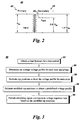
- Fig. 2 shows a schematic diagram of a conventional voltage regulator 110.
- Voltage regulator 110 includes a primary winding 42, a secondary winding 44, and transformer taps 46.
- a transformer has an equal number of winding turns on the primary winding and secondary winding, the input and output voltage will be equal.
- the output voltage can be changed. For example, if primary winding 42 has 120 turns and secondary winding 44 has 60 turns then the output to input voltage ratio will be one-half i.e., the output voltage on the secondary winding will be half of the input voltage on the primary winding.
- secondary winding 44 includes voltage taps 46.
- the output voltage at secondary winding 44 depends on taps between which the load is connected and can vary between 0.9 Vin to 1.1 Vin where Vin is the input voltage on the primary winding 42. There may be multiple taps (not shown) in between 0.9 Vin and 1.1 Vin for obtaining voltages in between.
- a tap changer has 32 taps, out of which 16 are for increasing the voltage (1 to 16 taps) whereas 16 are for decreasing the voltage (-1 to -16 taps).
- tap 10 when switched on may yield output voltage of 1.0625 Vin and tap -10 will yield output voltage of 0.9375 Vin.
- the actual tap setting and tap will vary depending on the application. For example, for a distribution transformer the output voltage need not go as low as 0.9 Vin but in certain conditions it may be necessary that the output voltage be higher than the input voltage. In another embodiment, the output voltage may need to be lower than 0.9 Vin.
- Fig. 3 shows a method 50 of operating a tap changer in accordance with an embodiment of the present invention.
- the method may be employed by the DMS 32 or EMS 28 ( FIG. 1 ), for example.
- the method includes obtaining a load forecast for a time period or period of interest in step 52.
- the load forecast may be determined in terms of MVA loading which is indicative of active as well as reactive power for a particular zone.
- the period of interest may be an hour, several hours, a day, or any other suitable time determined by the user or the operator.
- the load forecast is determined for k time steps into the future, where k is again a number determined by the operator.
- Load forecasting is useful in determining how much load each phase can have at any given time of the period of interest. This information may be used for running a load flow on the distribution system to estimate the state in terms of voltages at different points. Load forecasting techniques utilize various factors such as time, weather conditions, customer types, distribution system conditions, and historical load and weather data to provide a load forecast. As will be appreciated by those skilled in the art, load forecasting methods may include similar day approach, various regression models, time series, neural networks, expert systems, fuzzy logic, and statistical learning algorithms.
- a zone refers to an electrical network or a distribution system between two tap changers. For example, if a voltage is stepped down from 69 kV to 34.5 kV through a fixed step down transformer and it is further reduced to 12.47 kV through a second step down transformer at another distribution substation, then the electric system between the 34.5 kV to the second 12.47 kV will be considered as one zone. The voltages then may be determined for each node in the distribution system using the 12.47 kV as a base voltage for each phase of this zone.
- the base voltage value is utilized for normalizing quantities to a common base for calculation purposes.
- Tap changers or voltage regulators may be located at the output of the first step down transformer at the interconnection between the transmission system and the distribution system and at the second 12.47 kV substation to allow further adjustment of distribution voltage in the voltage ratio range of 0.9 to 1.1 per unit (pu).
- a load flow algorithm may be utilized. The load flow algorithm obtains complete voltage angle and magnitude information for each bus or each node on the distribution system for forecasted active and reactive loads. Since determining voltage information based on active and reactive load information is a nonlinear problem, numerical methods are employed to obtain a solution that is within an acceptable tolerance.
- Numerical methods for the load flow algorithm may include William Kersting's backward/forward sweep algorithm, for example.
- the average voltage profile then may be determined by calculating the average of all node voltages in the distribution system for each phase and time period. In one embodiment, the voltage profile is calculated with half of the taps of the tap changer being in the ON position. In other words, if there are 32 taps to the tap changer, each designed to increase the voltage (compared to 0 tap), then the voltage profile is determined with 16 taps of tap the changer being in the ON position. However, in other embodiments, the voltage profile may be determined with different tap positions.
- the tap positions of the tap changer for the period of interest are estimated in step 56 to level the voltage profile.
- leveling the voltage profile means obtaining a constant voltage throughout the period of interest.
- the voltage may not be absolutely constant and may include certain variations but the idea is that the overall voltage profile should not have significant variations.
- a certain amount of voltage called a flat voltage value or desired value may be fixed for the period of interest.
- the flat voltage value may be determined such that the number of tap position changes is minimized.
- the flat voltage value may be an average value of the minimum and maximum voltages of the voltage profile or in yet another embodiment, it could be a median value.
- the difference between the average voltage profile and the flat voltage value may be divided by the voltage per tap. If the flat voltage value is higher compared to the average voltage profile value, then one or more additional taps may be switched on. Otherwise, if the flat voltage value is lower compared to the average voltage profile value, one or more taps may be switched off depending upon the desired primary to secondary voltage ratio. For example, if the flat voltage value desired is 0.98 pu and if the forecasted average voltage at a particular time period is 0.9675 pu then to achieve 0.98 pu, two of the taps may be switched ON assuming 0.00625 pu volts/tap. Similarly, if the voltage is 0.88 pu then 16 taps may be switched ON.
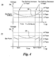
- FIG. 4 shows example plots 70 and 71 of voltage profiles determined in accordance with an embodiment of the present invention.
- Horizontal axis 72 in both plots 70, 71 represents time in hours whereas vertical axis 74 represents average voltage across all the nodes in a zone in per unit (pu).
- a predicted average voltage profile 76 varies from a minimum value of about two tap settings below the desired flat voltage value (for example, 0.98 pu) to a maximum value of about two tap settings above the desired flat voltage value over the period of 24 hours.
- plot 71 shows the resulting average voltage profile 77 based on the tap changer operation in accordance with an embodiment of the present invention.
- the resulting average voltage profile 77 is calculated with three adjustments in tap settings. The first tap change occurs at time 4 am with a 2 tap setting increase, the second and third tap changes with a 2 tap setting decrease at each adjustment occurs at 8 pm and 10 pm, respectively.
- the voltage may further may be increased or decreased to a defined voltage by a single tap change throughout the period of interest in step 58.
- a defined voltage For example, if the flat voltage value is 1.00125 pu and the defined voltage value is 0.98 pu then throughout the period of interest (e.g. 24 hours), the current tap setting is to be reduced by 3 taps (0.00625 pu volts/tap).
- the power flow algorithm with new identified tap settings may be utilized again before obtaining the defined voltage value to verify if any significant changes have occurred to the average voltage profile.
- the defined voltage may be determined by the utility company and is based on a conservation voltage reduction (CVR) factor.
- CVR conservation voltage reduction
- the CVR factor is the percentage reduction in load consumption resulting from a one percent reduction in the voltage. In certain embodiments, CVR factor may range from 0.4 to 1.0.
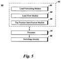
- FIG. 5 shows a tap changer control system 90 in accordance with an embodiment of the present invention.
- System 90 includes a processor 91 coupled to a memory 93 comprising a load forecasting module 92 for obtaining load forecasts for a time period which may be an hour or 24 hours or any other time as determined by the operator.
- module may refer to or include a computer program or code that provides the described functionality.
- a load flow module 94 runs a power flow on the load forecast data obtained from the load forecasting module 92 and determines an average voltage profile i.e., average voltage across all the nodes for each of the phases in a given zone for the time period.
- the zone may be an electric network between two tap changers.
- a tap position identification module 96 determines a flat voltage value to level the voltage profile and also estimates tap positions throughout the time period to achieve a flat voltage profile. In one embodiment, the module 96 may further identify tap positions for the period of interest to modify the flat voltage profiles to a predetermined voltage value profile wherein the predetermined voltage value may be determined based on the CVR factor.
- Processor 91 processes the data obtained from memory 93 and provides switching signal commands to a switching circuitry 98. In one embodiment, switching signal commands may be digital signals with 1 or 0 value. When the switching signal command is 1, it may mean the respective tap should be switched ON. Similarly, when the switching signal command is 0, it may be an indication to switch off the respective tap.
- Switching circuitry 98 When the switching signal command is ON, the respective tap will be switched ON whereas the tap will be switched OFF if the switching signal command is OFF.
- Switching circuitry 98 then provides switching signals to taps of a tap changer based on the modified tap positions determined for the period of interest by the tap position identification module 96.
Landscapes
- Engineering & Computer Science (AREA)
- Power Engineering (AREA)
- Physics & Mathematics (AREA)
- Electromagnetism (AREA)
- General Physics & Mathematics (AREA)
- Radar, Positioning & Navigation (AREA)
- Automation & Control Theory (AREA)
- Supply And Distribution Of Alternating Current (AREA)
- Control Of Electrical Variables (AREA)
Applications Claiming Priority (1)
| Application Number | Priority Date | Filing Date | Title |
|---|---|---|---|
| US13/077,504 US8531173B2 (en) | 2011-03-31 | 2011-03-31 | System and method for operating a tap changer |
Publications (2)
| Publication Number | Publication Date |
|---|---|
| EP2506384A1 EP2506384A1 (en) | 2012-10-03 |
| EP2506384B1 true EP2506384B1 (en) | 2016-08-03 |
Family
ID=46044348
Family Applications (1)
| Application Number | Title | Priority Date | Filing Date |
|---|---|---|---|
| EP12161899.5A Not-in-force EP2506384B1 (en) | 2011-03-31 | 2012-03-28 | System and method for operating a tap changer |
Country Status (3)
| Country | Link |
|---|---|
| US (1) | US8531173B2 (enExample) |
| EP (1) | EP2506384B1 (enExample) |
| JP (1) | JP2012217332A (enExample) |
Families Citing this family (32)
| Publication number | Priority date | Publication date | Assignee | Title |
|---|---|---|---|---|
| EP2700061A4 (en) | 2011-04-22 | 2014-11-19 | Expanergy Llc | SYSTEMS AND METHOD FOR ANALYZING ENERGY CONSUMPTION |
| US20130024033A1 (en) * | 2011-07-20 | 2013-01-24 | General Electric Company | Systems and methods for a power distribution transfer capacity calculator |
| BRPI1106471B1 (pt) * | 2011-10-17 | 2020-12-22 | Companhia Hidro Elétrica Do São Francisco - Chesf | método de regulação de tensão e paralelismo entre diferentes modelos de fontes de tensão e/ou vãos energizados de alta tensão |
| US9281756B2 (en) * | 2011-11-11 | 2016-03-08 | Varentec, Inc. | Power flow controller with a fractionally rated back-to-back converter |
| CA2856887C (en) | 2011-11-28 | 2021-06-15 | Expanergy, Llc | Energy search engine with autonomous control |
| US9582020B2 (en) | 2013-03-15 | 2017-02-28 | Dominion Resources, Inc. | Maximizing of energy delivery system compatibility with voltage optimization using AMI-based data control and analysis |
| US9678520B2 (en) | 2013-03-15 | 2017-06-13 | Dominion Resources, Inc. | Electric power system control with planning of energy demand and energy efficiency using AMI-based data analysis |
| US9847639B2 (en) | 2013-03-15 | 2017-12-19 | Dominion Energy, Inc. | Electric power system control with measurement of energy demand and energy efficiency |
| US9553453B2 (en) | 2013-03-15 | 2017-01-24 | Dominion Resources, Inc. | Management of energy demand and energy efficiency savings from voltage optimization on electric power systems using AMI-based data analysis |
| US9563218B2 (en) | 2013-03-15 | 2017-02-07 | Dominion Resources, Inc. | Electric power system control with measurement of energy demand and energy efficiency using t-distributions |
| CN103257591B (zh) * | 2013-03-29 | 2015-11-18 | 国家电网公司 | 一种分接头升降指令仿真装置 |
| JP6191229B2 (ja) * | 2013-05-15 | 2017-09-06 | 富士電機株式会社 | タップ計画値算出方法及びこれを用いたタップ指令値の決定方法、制御目標値算出方法、並びにタップ計画値算出装置、タップ指令値決定装置、タップ計画値算出プログラム |
| US9729678B2 (en) | 2013-10-03 | 2017-08-08 | Duke Energy Corporation | Methods of processing data corresponding to a device that corresponds to a gas, water, or electric grid, and related devices and computer program products |
| CN103618379B (zh) * | 2013-10-22 | 2017-03-29 | 芜湖大学科技园发展有限公司 | 一种动态、可扩展的电网开关估计系统 |
| DE102013224411A1 (de) | 2013-11-26 | 2015-05-28 | Siemens Aktiengesellschaft | Verfahren zur rechnergestützten Konfiguration eines elektrischen Stromnetzes |
| CN103872681A (zh) * | 2014-03-25 | 2014-06-18 | 国家电网公司 | 一种基于主配网一体化的在线实时合环方法 |
| JP6448032B2 (ja) * | 2015-03-06 | 2019-01-09 | 東京電力ホールディングス株式会社 | Dr制御システムおよびdr制御方法 |
| US10116135B1 (en) * | 2015-05-08 | 2018-10-30 | Statistics & Control, Inc. | Method and apparatus for voltage control in electric power systems |
| US10732656B2 (en) | 2015-08-24 | 2020-08-04 | Dominion Energy, Inc. | Systems and methods for stabilizer control |
| CN110383201B (zh) | 2015-11-09 | 2022-01-18 | 日立能源瑞士股份公司 | 功率设备控制器和配电系统 |
| JP6752071B2 (ja) * | 2016-07-19 | 2020-09-09 | 株式会社日立製作所 | 配電系統の系統最適化計算装置および系統最適化計算方法 |
| CN106300396A (zh) * | 2016-08-29 | 2017-01-04 | 华北电力大学(保定) | 实现三相负荷平衡的电动汽车充电开关装置及充电方法 |
| US10048709B2 (en) * | 2016-09-19 | 2018-08-14 | General Electric Company | System and method for regulation of voltage on an electric power system |
| CN109840646A (zh) * | 2017-11-27 | 2019-06-04 | 国网辽宁省电力有限公司经济技术研究院 | 基于大数据处理的电压监测方法 |
| GB2569910B (en) | 2018-03-23 | 2020-04-29 | Electricity North West Property Ltd | System for frequency regulation on a power distribution network |
| KR102192000B1 (ko) * | 2020-04-29 | 2020-12-16 | 주식회사 시너지 | 분산형 발전 설비의 발전 효율 향상 장치 및 방법 |
| EP4214526A4 (en) * | 2020-10-06 | 2024-10-30 | AVO Multi-Amp Corporation DBA Megger, Inc. | TRANSFORMER TEST SYSTEM AND METHODS |
| EP3989382A1 (en) * | 2020-10-26 | 2022-04-27 | Siemens Gamesa Renewable Energy Innovation & Technology S.L. | Wind turbine auxiliary power system |
| CN112994040B (zh) * | 2021-02-26 | 2022-06-14 | 广东电网有限责任公司韶关供电局 | 一种变压器电压调节方法及变压器 |
| ES2950896B2 (es) * | 2022-03-10 | 2024-12-02 | Ormazabal Corporate Tech A I E | Método de determinación de la consigna óptima y de la política de control de un regulador automático de tensión para transformadores con cambiador de tomas eléctricas en carga |
| CN114696693B (zh) * | 2022-06-01 | 2022-08-26 | 山东东辰节能电力设备有限公司 | 一种智能调容变压器 |
| CN119628220B (zh) * | 2024-11-26 | 2025-07-25 | 广东华井科技有限公司 | 一种换流变压器有载分接开关控制系统及方法 |
Family Cites Families (18)
| Publication number | Priority date | Publication date | Assignee | Title |
|---|---|---|---|---|
| JPS6198126A (ja) * | 1984-10-19 | 1986-05-16 | 株式会社東芝 | 電圧制御装置 |
| JPS63299722A (ja) * | 1987-05-28 | 1988-12-07 | Hitachi Ltd | 電圧調整継電器 |
| JP2734207B2 (ja) | 1991-01-17 | 1998-03-30 | 株式会社日立製作所 | 系統電圧制御方法及び装置 |
| JP2515076B2 (ja) * | 1992-02-28 | 1996-07-10 | 東北電力株式会社 | 電圧無効電力の制御方法及び装置 |
| JPH05328608A (ja) | 1992-05-22 | 1993-12-10 | Tohoku Electric Power Co Inc | 電圧無効電力制御装置 |
| US5541498A (en) * | 1994-12-08 | 1996-07-30 | Beckwith; Robert W. | Distribution circuit var management system using adaptive capacitor controls |
| JP2002271988A (ja) * | 2001-03-07 | 2002-09-20 | Kawamura Electric Inc | 節電装置 |
| JP2004173384A (ja) | 2002-11-19 | 2004-06-17 | Mitsubishi Electric Corp | 自動電圧調整装置 |
| US6924565B2 (en) * | 2003-08-18 | 2005-08-02 | General Electric Company | Continuous reactive power support for wind turbine generators |
| BRPI0601093A (pt) | 2006-02-17 | 2007-11-06 | Eduardo Pedrosa Santos | sistema para regulação de tensão, controle, proteção e monitoração de estado de comutadores sob carga de transformadores de potência, reguladores de tensão, bancos de capacitores e congêneres |
| US7444266B2 (en) | 2006-03-21 | 2008-10-28 | Abb Technology Ltd. | Control system for a transformer or reactor |
| EP2362978B1 (en) * | 2008-11-05 | 2013-01-02 | ABB Research Ltd. | Reactive power optimization |
| AU2010204729A1 (en) * | 2009-01-14 | 2011-09-01 | Integral Analytics, Inc. | Optimization of microgrid energy use and distribution |
| EP2394347B1 (en) * | 2009-02-05 | 2017-08-23 | ABB Research Ltd. | Integrated voltage and var optimization process for a distribution system |
| DK2427949T3 (da) * | 2009-05-07 | 2020-06-29 | Virginia Electric And Power Company | Voltage conservation using advanced metering infrastructure and substation centralized voltage control |
| US8476874B2 (en) * | 2009-10-13 | 2013-07-02 | Schweitzer Engineering Laboratories, Inc | Systems and methods for synchronized control of electrical power system voltage profiles |
| CA2731433C (en) * | 2010-02-09 | 2018-05-15 | Open Access Technology International, Inc. | Systems and methods for demand response and distributed energy resource management |
| US9282383B2 (en) * | 2011-01-14 | 2016-03-08 | Trilliant Incorporated | Process, device and system for volt/VAR optimization |
-
2011
- 2011-03-31 US US13/077,504 patent/US8531173B2/en not_active Expired - Fee Related
-
2012
- 2012-03-28 EP EP12161899.5A patent/EP2506384B1/en not_active Not-in-force
- 2012-03-29 JP JP2012075355A patent/JP2012217332A/ja active Pending
Also Published As
| Publication number | Publication date |
|---|---|
| JP2012217332A (ja) | 2012-11-08 |
| US20120249278A1 (en) | 2012-10-04 |
| EP2506384A1 (en) | 2012-10-03 |
| US8531173B2 (en) | 2013-09-10 |
Similar Documents
| Publication | Publication Date | Title |
|---|---|---|
| EP2506384B1 (en) | System and method for operating a tap changer | |
| US10868425B1 (en) | Method to detect utility disturbance and fault direction | |
| US11157031B2 (en) | Systems and methods for volt/VAR control in electric power management and automation systems | |
| KR102101108B1 (ko) | 무효 전력 제어 방법, 디바이스 및 시스템 | |
| Viawan et al. | Combined local and remote voltage and reactive power control in the presence of induction machine distributed generation | |
| US8392031B2 (en) | System and method for load forecasting | |
| EP2506383B1 (en) | System and method for operating capacitor banks | |
| Shafiu et al. | Active management and protection of distribution networks with distributed generation | |
| KR102512324B1 (ko) | 재생 에너지를 연계한 부하 예측 모델 기반의 전압 최적화 제어를 통한 보전 전압 강하를 위한 전압 제어 장치 | |
| CN112467753B (zh) | 一种无功置换方法及装置 | |
| Ishii et al. | Optimal smart functions of large-scale PV inverters in distribution systems | |
| CN107846025B (zh) | 用于调节电力系统电压的系统和方法 | |
| Jha et al. | Enhancing conservation voltage reduction using coordinated control of medium and low voltage controllable devices | |
| WO2020025169A1 (en) | Adaptive voltage bandwidth for a voltage regulation device | |
| JP7580350B2 (ja) | 電圧制御装置、電圧制御方法および電圧制御システム | |
| US11146102B2 (en) | Method and control center arrangement for the control of an electrical energy transmission grid, and computer program product | |
| EP4704281A1 (en) | Computer-implemented method, system and computer program product for optimizing an electric power distribution network | |
| Mandal et al. | Coordinated capacitor bank switching using SVC controls | |
| Ilić et al. | AC-extended optimal power flow (AC XOPF) for reliable grid operations and planning in support of energy transition: Puerto Rico power grid case | |
| JP2018011391A (ja) | 電圧監視制御装置 | |
| Kojovic et al. | Centralized voltage-var regulation in distribution network | |
| Franz et al. | Analysis of an Advanced Compounding Strategy based on Reactive Power Flow Measurement in the Medium Voltage Network |
Legal Events
| Date | Code | Title | Description |
|---|---|---|---|
| PUAI | Public reference made under article 153(3) epc to a published international application that has entered the european phase |
Free format text: ORIGINAL CODE: 0009012 |
|
| AK | Designated contracting states |
Kind code of ref document: A1 Designated state(s): AL AT BE BG CH CY CZ DE DK EE ES FI FR GB GR HR HU IE IS IT LI LT LU LV MC MK MT NL NO PL PT RO RS SE SI SK SM TR |
|
| AX | Request for extension of the european patent |
Extension state: BA ME |
|
| 17P | Request for examination filed |
Effective date: 20130403 |
|
| REG | Reference to a national code |
Ref country code: DE Ref legal event code: R079 Ref document number: 602012021153 Country of ref document: DE Free format text: PREVIOUS MAIN CLASS: H02J0003180000 Ipc: H02J0003160000 |
|
| RIC1 | Information provided on ipc code assigned before grant |
Ipc: G05F 1/14 20060101ALI20160203BHEP Ipc: H02J 3/00 20060101ALI20160203BHEP Ipc: H02J 3/18 20060101ALI20160203BHEP Ipc: H02P 13/06 20060101ALI20160203BHEP Ipc: H02J 3/16 20060101AFI20160203BHEP |
|
| GRAP | Despatch of communication of intention to grant a patent |
Free format text: ORIGINAL CODE: EPIDOSNIGR1 |
|
| INTG | Intention to grant announced |
Effective date: 20160415 |
|
| GRAS | Grant fee paid |
Free format text: ORIGINAL CODE: EPIDOSNIGR3 |
|
| GRAA | (expected) grant |
Free format text: ORIGINAL CODE: 0009210 |
|
| AK | Designated contracting states |
Kind code of ref document: B1 Designated state(s): AL AT BE BG CH CY CZ DE DK EE ES FI FR GB GR HR HU IE IS IT LI LT LU LV MC MK MT NL NO PL PT RO RS SE SI SK SM TR |
|
| REG | Reference to a national code |
Ref country code: GB Ref legal event code: FG4D |
|
| REG | Reference to a national code |
Ref country code: CH Ref legal event code: EP Ref country code: AT Ref legal event code: REF Ref document number: 817898 Country of ref document: AT Kind code of ref document: T Effective date: 20160815 |
|
| REG | Reference to a national code |
Ref country code: IE Ref legal event code: FG4D |
|
| REG | Reference to a national code |
Ref country code: DE Ref legal event code: R096 Ref document number: 602012021153 Country of ref document: DE |
|
| REG | Reference to a national code |
Ref country code: NL Ref legal event code: MP Effective date: 20160803 |
|
| REG | Reference to a national code |
Ref country code: LT Ref legal event code: MG4D |
|
| REG | Reference to a national code |
Ref country code: AT Ref legal event code: MK05 Ref document number: 817898 Country of ref document: AT Kind code of ref document: T Effective date: 20160803 |
|
| PG25 | Lapsed in a contracting state [announced via postgrant information from national office to epo] |
Ref country code: HR Free format text: LAPSE BECAUSE OF FAILURE TO SUBMIT A TRANSLATION OF THE DESCRIPTION OR TO PAY THE FEE WITHIN THE PRESCRIBED TIME-LIMIT Effective date: 20160803 Ref country code: LT Free format text: LAPSE BECAUSE OF FAILURE TO SUBMIT A TRANSLATION OF THE DESCRIPTION OR TO PAY THE FEE WITHIN THE PRESCRIBED TIME-LIMIT Effective date: 20160803 Ref country code: NL Free format text: LAPSE BECAUSE OF FAILURE TO SUBMIT A TRANSLATION OF THE DESCRIPTION OR TO PAY THE FEE WITHIN THE PRESCRIBED TIME-LIMIT Effective date: 20160803 Ref country code: RS Free format text: LAPSE BECAUSE OF FAILURE TO SUBMIT A TRANSLATION OF THE DESCRIPTION OR TO PAY THE FEE WITHIN THE PRESCRIBED TIME-LIMIT Effective date: 20160803 Ref country code: FI Free format text: LAPSE BECAUSE OF FAILURE TO SUBMIT A TRANSLATION OF THE DESCRIPTION OR TO PAY THE FEE WITHIN THE PRESCRIBED TIME-LIMIT Effective date: 20160803 Ref country code: IT Free format text: LAPSE BECAUSE OF FAILURE TO SUBMIT A TRANSLATION OF THE DESCRIPTION OR TO PAY THE FEE WITHIN THE PRESCRIBED TIME-LIMIT Effective date: 20160803 Ref country code: NO Free format text: LAPSE BECAUSE OF FAILURE TO SUBMIT A TRANSLATION OF THE DESCRIPTION OR TO PAY THE FEE WITHIN THE PRESCRIBED TIME-LIMIT Effective date: 20161103 Ref country code: IS Free format text: LAPSE BECAUSE OF FAILURE TO SUBMIT A TRANSLATION OF THE DESCRIPTION OR TO PAY THE FEE WITHIN THE PRESCRIBED TIME-LIMIT Effective date: 20161203 |
|
| PG25 | Lapsed in a contracting state [announced via postgrant information from national office to epo] |
Ref country code: ES Free format text: LAPSE BECAUSE OF FAILURE TO SUBMIT A TRANSLATION OF THE DESCRIPTION OR TO PAY THE FEE WITHIN THE PRESCRIBED TIME-LIMIT Effective date: 20160803 Ref country code: SE Free format text: LAPSE BECAUSE OF FAILURE TO SUBMIT A TRANSLATION OF THE DESCRIPTION OR TO PAY THE FEE WITHIN THE PRESCRIBED TIME-LIMIT Effective date: 20160803 Ref country code: PL Free format text: LAPSE BECAUSE OF FAILURE TO SUBMIT A TRANSLATION OF THE DESCRIPTION OR TO PAY THE FEE WITHIN THE PRESCRIBED TIME-LIMIT Effective date: 20160803 Ref country code: GR Free format text: LAPSE BECAUSE OF FAILURE TO SUBMIT A TRANSLATION OF THE DESCRIPTION OR TO PAY THE FEE WITHIN THE PRESCRIBED TIME-LIMIT Effective date: 20161104 Ref country code: PT Free format text: LAPSE BECAUSE OF FAILURE TO SUBMIT A TRANSLATION OF THE DESCRIPTION OR TO PAY THE FEE WITHIN THE PRESCRIBED TIME-LIMIT Effective date: 20161205 Ref country code: LV Free format text: LAPSE BECAUSE OF FAILURE TO SUBMIT A TRANSLATION OF THE DESCRIPTION OR TO PAY THE FEE WITHIN THE PRESCRIBED TIME-LIMIT Effective date: 20160803 Ref country code: AT Free format text: LAPSE BECAUSE OF FAILURE TO SUBMIT A TRANSLATION OF THE DESCRIPTION OR TO PAY THE FEE WITHIN THE PRESCRIBED TIME-LIMIT Effective date: 20160803 |
|
| REG | Reference to a national code |
Ref country code: FR Ref legal event code: PLFP Year of fee payment: 6 |
|
| PG25 | Lapsed in a contracting state [announced via postgrant information from national office to epo] |
Ref country code: RO Free format text: LAPSE BECAUSE OF FAILURE TO SUBMIT A TRANSLATION OF THE DESCRIPTION OR TO PAY THE FEE WITHIN THE PRESCRIBED TIME-LIMIT Effective date: 20160803 Ref country code: EE Free format text: LAPSE BECAUSE OF FAILURE TO SUBMIT A TRANSLATION OF THE DESCRIPTION OR TO PAY THE FEE WITHIN THE PRESCRIBED TIME-LIMIT Effective date: 20160803 |
|
| REG | Reference to a national code |
Ref country code: DE Ref legal event code: R097 Ref document number: 602012021153 Country of ref document: DE |
|
| PG25 | Lapsed in a contracting state [announced via postgrant information from national office to epo] |
Ref country code: BG Free format text: LAPSE BECAUSE OF FAILURE TO SUBMIT A TRANSLATION OF THE DESCRIPTION OR TO PAY THE FEE WITHIN THE PRESCRIBED TIME-LIMIT Effective date: 20161103 Ref country code: CZ Free format text: LAPSE BECAUSE OF FAILURE TO SUBMIT A TRANSLATION OF THE DESCRIPTION OR TO PAY THE FEE WITHIN THE PRESCRIBED TIME-LIMIT Effective date: 20160803 Ref country code: DK Free format text: LAPSE BECAUSE OF FAILURE TO SUBMIT A TRANSLATION OF THE DESCRIPTION OR TO PAY THE FEE WITHIN THE PRESCRIBED TIME-LIMIT Effective date: 20160803 Ref country code: SK Free format text: LAPSE BECAUSE OF FAILURE TO SUBMIT A TRANSLATION OF THE DESCRIPTION OR TO PAY THE FEE WITHIN THE PRESCRIBED TIME-LIMIT Effective date: 20160803 Ref country code: BE Free format text: LAPSE BECAUSE OF FAILURE TO SUBMIT A TRANSLATION OF THE DESCRIPTION OR TO PAY THE FEE WITHIN THE PRESCRIBED TIME-LIMIT Effective date: 20160803 Ref country code: SM Free format text: LAPSE BECAUSE OF FAILURE TO SUBMIT A TRANSLATION OF THE DESCRIPTION OR TO PAY THE FEE WITHIN THE PRESCRIBED TIME-LIMIT Effective date: 20160803 |
|
| PLBE | No opposition filed within time limit |
Free format text: ORIGINAL CODE: 0009261 |
|
| STAA | Information on the status of an ep patent application or granted ep patent |
Free format text: STATUS: NO OPPOSITION FILED WITHIN TIME LIMIT |
|
| 26N | No opposition filed |
Effective date: 20170504 |
|
| PG25 | Lapsed in a contracting state [announced via postgrant information from national office to epo] |
Ref country code: SI Free format text: LAPSE BECAUSE OF FAILURE TO SUBMIT A TRANSLATION OF THE DESCRIPTION OR TO PAY THE FEE WITHIN THE PRESCRIBED TIME-LIMIT Effective date: 20160803 |
|
| REG | Reference to a national code |
Ref country code: CH Ref legal event code: PL |
|
| PG25 | Lapsed in a contracting state [announced via postgrant information from national office to epo] |
Ref country code: MC Free format text: LAPSE BECAUSE OF FAILURE TO SUBMIT A TRANSLATION OF THE DESCRIPTION OR TO PAY THE FEE WITHIN THE PRESCRIBED TIME-LIMIT Effective date: 20160803 |
|
| REG | Reference to a national code |
Ref country code: IE Ref legal event code: MM4A |
|
| PG25 | Lapsed in a contracting state [announced via postgrant information from national office to epo] |
Ref country code: LU Free format text: LAPSE BECAUSE OF NON-PAYMENT OF DUE FEES Effective date: 20170328 |
|
| PG25 | Lapsed in a contracting state [announced via postgrant information from national office to epo] |
Ref country code: CH Free format text: LAPSE BECAUSE OF NON-PAYMENT OF DUE FEES Effective date: 20170331 Ref country code: IE Free format text: LAPSE BECAUSE OF NON-PAYMENT OF DUE FEES Effective date: 20170328 Ref country code: LI Free format text: LAPSE BECAUSE OF NON-PAYMENT OF DUE FEES Effective date: 20170331 |
|
| REG | Reference to a national code |
Ref country code: FR Ref legal event code: PLFP Year of fee payment: 7 |
|
| PG25 | Lapsed in a contracting state [announced via postgrant information from national office to epo] |
Ref country code: MT Free format text: LAPSE BECAUSE OF NON-PAYMENT OF DUE FEES Effective date: 20170328 |
|
| PG25 | Lapsed in a contracting state [announced via postgrant information from national office to epo] |
Ref country code: AL Free format text: LAPSE BECAUSE OF FAILURE TO SUBMIT A TRANSLATION OF THE DESCRIPTION OR TO PAY THE FEE WITHIN THE PRESCRIBED TIME-LIMIT Effective date: 20160803 |
|
| PG25 | Lapsed in a contracting state [announced via postgrant information from national office to epo] |
Ref country code: HU Free format text: LAPSE BECAUSE OF FAILURE TO SUBMIT A TRANSLATION OF THE DESCRIPTION OR TO PAY THE FEE WITHIN THE PRESCRIBED TIME-LIMIT; INVALID AB INITIO Effective date: 20120328 |
|
| PG25 | Lapsed in a contracting state [announced via postgrant information from national office to epo] |
Ref country code: CY Free format text: LAPSE BECAUSE OF NON-PAYMENT OF DUE FEES Effective date: 20160803 |
|
| PG25 | Lapsed in a contracting state [announced via postgrant information from national office to epo] |
Ref country code: MK Free format text: LAPSE BECAUSE OF FAILURE TO SUBMIT A TRANSLATION OF THE DESCRIPTION OR TO PAY THE FEE WITHIN THE PRESCRIBED TIME-LIMIT Effective date: 20160803 |
|
| PG25 | Lapsed in a contracting state [announced via postgrant information from national office to epo] |
Ref country code: TR Free format text: LAPSE BECAUSE OF FAILURE TO SUBMIT A TRANSLATION OF THE DESCRIPTION OR TO PAY THE FEE WITHIN THE PRESCRIBED TIME-LIMIT Effective date: 20160803 |
|
| P01 | Opt-out of the competence of the unified patent court (upc) registered |
Effective date: 20230522 |
|
| REG | Reference to a national code |
Ref country code: DE Ref legal event code: R081 Ref document number: 602012021153 Country of ref document: DE Owner name: GENERAL ELECTRIC TECHNOLOGY GMBH, CH Free format text: FORMER OWNER: GENERAL ELECTRIC CO., SCHENECTADY, N.Y., US |
|
| REG | Reference to a national code |
Ref country code: GB Ref legal event code: 732E Free format text: REGISTERED BETWEEN 20240222 AND 20240228 |
|
| PGFP | Annual fee paid to national office [announced via postgrant information from national office to epo] |
Ref country code: DE Payment date: 20240220 Year of fee payment: 13 Ref country code: GB Payment date: 20240220 Year of fee payment: 13 |
|
| PGFP | Annual fee paid to national office [announced via postgrant information from national office to epo] |
Ref country code: FR Payment date: 20240220 Year of fee payment: 13 |
|
| REG | Reference to a national code |
Ref country code: DE Ref legal event code: R119 Ref document number: 602012021153 Country of ref document: DE |
|
| GBPC | Gb: european patent ceased through non-payment of renewal fee |
Effective date: 20250328 |
|
| PG25 | Lapsed in a contracting state [announced via postgrant information from national office to epo] |
Ref country code: DE Free format text: LAPSE BECAUSE OF NON-PAYMENT OF DUE FEES Effective date: 20251001 |
|
| PG25 | Lapsed in a contracting state [announced via postgrant information from national office to epo] |
Ref country code: GB Free format text: LAPSE BECAUSE OF NON-PAYMENT OF DUE FEES Effective date: 20250328 |
|
| PG25 | Lapsed in a contracting state [announced via postgrant information from national office to epo] |
Ref country code: FR Free format text: LAPSE BECAUSE OF NON-PAYMENT OF DUE FEES Effective date: 20250331 |