EP2505902A2 - Formrohr für ein Abschnittsheizungsrohr mit Schersteuerungsring und Verfahren dafür - Google Patents
Formrohr für ein Abschnittsheizungsrohr mit Schersteuerungsring und Verfahren dafür Download PDFInfo
- Publication number
- EP2505902A2 EP2505902A2 EP11181781A EP11181781A EP2505902A2 EP 2505902 A2 EP2505902 A2 EP 2505902A2 EP 11181781 A EP11181781 A EP 11181781A EP 11181781 A EP11181781 A EP 11181781A EP 2505902 A2 EP2505902 A2 EP 2505902A2
- Authority
- EP
- European Patent Office
- Prior art keywords
- pipe
- shear control
- control ring
- internal pipe
- shear
- Prior art date
- Legal status (The legal status is an assumption and is not a legal conclusion. Google has not performed a legal analysis and makes no representation as to the accuracy of the status listed.)
- Granted
Links
Images


Classifications
-
- F—MECHANICAL ENGINEERING; LIGHTING; HEATING; WEAPONS; BLASTING
- F16—ENGINEERING ELEMENTS AND UNITS; GENERAL MEASURES FOR PRODUCING AND MAINTAINING EFFECTIVE FUNCTIONING OF MACHINES OR INSTALLATIONS; THERMAL INSULATION IN GENERAL
- F16L—PIPES; JOINTS OR FITTINGS FOR PIPES; SUPPORTS FOR PIPES, CABLES OR PROTECTIVE TUBING; MEANS FOR THERMAL INSULATION IN GENERAL
- F16L43/00—Bends; Siphons
- F16L43/02—Bends; Siphons adapted to make use of special securing means
-
- F—MECHANICAL ENGINEERING; LIGHTING; HEATING; WEAPONS; BLASTING
- F16—ENGINEERING ELEMENTS AND UNITS; GENERAL MEASURES FOR PRODUCING AND MAINTAINING EFFECTIVE FUNCTIONING OF MACHINES OR INSTALLATIONS; THERMAL INSULATION IN GENERAL
- F16L—PIPES; JOINTS OR FITTINGS FOR PIPES; SUPPORTS FOR PIPES, CABLES OR PROTECTIVE TUBING; MEANS FOR THERMAL INSULATION IN GENERAL
- F16L59/00—Thermal insulation in general
- F16L59/14—Arrangements for the insulation of pipes or pipe systems
- F16L59/16—Arrangements specially adapted to local requirements at flanges, junctions, valves or the like
- F16L59/22—Arrangements specially adapted to local requirements at flanges, junctions, valves or the like adapted for bends
-
- F—MECHANICAL ENGINEERING; LIGHTING; HEATING; WEAPONS; BLASTING
- F16—ENGINEERING ELEMENTS AND UNITS; GENERAL MEASURES FOR PRODUCING AND MAINTAINING EFFECTIVE FUNCTIONING OF MACHINES OR INSTALLATIONS; THERMAL INSULATION IN GENERAL
- F16L—PIPES; JOINTS OR FITTINGS FOR PIPES; SUPPORTS FOR PIPES, CABLES OR PROTECTIVE TUBING; MEANS FOR THERMAL INSULATION IN GENERAL
- F16L59/00—Thermal insulation in general
- F16L59/10—Bandages or covers for the protection of the insulation, e.g. against the influence of the environment or against mechanical damage
-
- F—MECHANICAL ENGINEERING; LIGHTING; HEATING; WEAPONS; BLASTING
- F16—ENGINEERING ELEMENTS AND UNITS; GENERAL MEASURES FOR PRODUCING AND MAINTAINING EFFECTIVE FUNCTIONING OF MACHINES OR INSTALLATIONS; THERMAL INSULATION IN GENERAL
- F16L—PIPES; JOINTS OR FITTINGS FOR PIPES; SUPPORTS FOR PIPES, CABLES OR PROTECTIVE TUBING; MEANS FOR THERMAL INSULATION IN GENERAL
- F16L9/00—Rigid pipes
- F16L9/18—Double-walled pipes; Multi-channel pipes or pipe assemblies
-
- F—MECHANICAL ENGINEERING; LIGHTING; HEATING; WEAPONS; BLASTING
- F24—HEATING; RANGES; VENTILATING
- F24D—DOMESTIC- OR SPACE-HEATING SYSTEMS, e.g. CENTRAL HEATING SYSTEMS; DOMESTIC HOT-WATER SUPPLY SYSTEMS; ELEMENTS OR COMPONENTS THEREFOR
- F24D10/00—District heating systems
-
- F—MECHANICAL ENGINEERING; LIGHTING; HEATING; WEAPONS; BLASTING
- F16—ENGINEERING ELEMENTS AND UNITS; GENERAL MEASURES FOR PRODUCING AND MAINTAINING EFFECTIVE FUNCTIONING OF MACHINES OR INSTALLATIONS; THERMAL INSULATION IN GENERAL
- F16L—PIPES; JOINTS OR FITTINGS FOR PIPES; SUPPORTS FOR PIPES, CABLES OR PROTECTIVE TUBING; MEANS FOR THERMAL INSULATION IN GENERAL
- F16L2201/00—Special arrangements for pipe couplings
- F16L2201/30—Detecting leaks
-
- Y—GENERAL TAGGING OF NEW TECHNOLOGICAL DEVELOPMENTS; GENERAL TAGGING OF CROSS-SECTIONAL TECHNOLOGIES SPANNING OVER SEVERAL SECTIONS OF THE IPC; TECHNICAL SUBJECTS COVERED BY FORMER USPC CROSS-REFERENCE ART COLLECTIONS [XRACs] AND DIGESTS
- Y02—TECHNOLOGIES OR APPLICATIONS FOR MITIGATION OR ADAPTATION AGAINST CLIMATE CHANGE
- Y02E—REDUCTION OF GREENHOUSE GAS [GHG] EMISSIONS, RELATED TO ENERGY GENERATION, TRANSMISSION OR DISTRIBUTION
- Y02E20/00—Combustion technologies with mitigation potential
- Y02E20/14—Combined heat and power generation [CHP]
Definitions
- the present application relates to a shape tube for district heating heat pipe having shear control ring, more specifically, a shape tube for district heating heat pipe having shear control ring for dispersing shear stress, delivered to heat insulators, by applying shear control ring(SCR) to the curves of the internal pipe of curvedly bent heat pipes.
- SCR shear control ring
- Heat pipes refer to heat transfer facilities for supplying heat for district cooling and heating and are used to deliver heat for district cooling and heating, generated in heat generation facilities, to user mechanical facilities.
- Heat supply pipes are currently used as dual insulated pipes, not single insulated pipes in the nation, and heat pipes are commonly used as dual insulated pipes for the reasons of insulation, economics, etc., referring to underground pipelines.
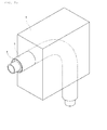
- Fig. 1 illustrates the structure of general dual insulated pipes, comprising: internal pipe(1) made with steel; heat insulator(3) like polyurethane; external pipe(5) made with steel or synthetic resins; and leakage sensing line(7).
- the object of the present application is to provide a shape tube for district heating heat pipe having shear control ring for dispersing shear stress, delivered to a heat insulator, by applying shear control ring(SCR) to curves of the internal pipe of heat pipes bent with constant curvature.
- the present invention is characterized by comprising: an internal pipe, bent with constant curvature, connecting the district heating heat pipe and both ends and flowing medium-temperature hot water inside the internal pipe; an external pipe forming a space and inserting the internal pipe inside, having large diameter than that of the internal pipe; a heat insulator foamed in the space between the internal pipe and the external pipe; and a shear control ring combined to the curves of the internal pipe.
- a spacer maintaining the above space when assembly is further comprised between the internal pipe and the external pipe.
- a leakage sensing line longitudinally installed between the internal pipe and the external pipe and fixed by the heat insulator is further comprised.
- the shear control ring made with metal, has an inside diameter which presses the internal pipe, and is installed by N-numbers.
- the N refers to odd numbers.
- one shear control ring is installed to the center line (C1) of the curves when installing one shear control ring to the curves of the internal pipe.
- one of shear control rings is installed to the center line (C1) of the curves and the rest of shear control rings is formed toward any one point (P1), extended from the center line (C1) of the curves, having the same angle in both directions, respectively.
- the shear control ring has a height wherein the shear control ring is not contacted with the inner side of the external pipe.
- shear control ring is combined by TIG welding to the curves of the internal pipe.
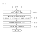
- the method for manufacturing the shape tube for district heating heat pipe having shear control ring of the present invention comprises processes of: manufacturing the shear control ring having a diameter pressed in the external side of the internal pipe by cutting a hollow metal pipe or plate with a cutter; sticking the shear control ring by TIG welding after pressing the shear control ring in the curves of the internal pipe; assembling and inserting the internal pipe, to which the shear control ring is stuck, into the external pipe; and foaming the heat insulator by filling the heat insulator between the external pipe and the internal pipe.
- the sticking process further performs liquid penetrant non-destructive testing after sticking the shear control ring.
- the effect is to prevent transform in heat pipes in advance by installing shear control rings in the curves of the internal pipe of heat pipes bent with constant curvature and dispersing shear stress, delivered to a heat insulator.
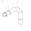
- Fig. 3 is a skew drawing showing the constitution of shape tube for district heating heat pipe having shear control ring
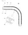
- Fig. 4 is a sectional drawing of Fig. 3
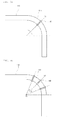
- Figs. 5a and 5b are side views showing the constitution of internal pipes of shape tube for district heating heat pipe having shear control ring according to the present invention.
- a shape tube for district heating heat pipe having shear control ring comprises an internal pipe (110), an external pipe (120), a heat insulator(130), and a shear control ring (140).
- the internal pipe (110) made with metal, comprises a curve (111) bent with constant curvature, wherein both ends are connected to the district heating heat pipes(not illustrated) and medium-temperature hot water is flowed into the inside.
- the internal pipe (110) further includes a plurality of spacers (113) to external sides.
- the external pipe (120) made with metal or synthetic resins, has larger diameter than that of the internal pipe (110) for comprising a space (121) inside when inserting the internal pipe (110), wherein a gap is maintained by the spacer (113) with inserting the internal pipe (110) to the inside center.
- the external pipe (120) further includes the leakage sensing line (123) longitudinally installed inside the external pipe (120) and fixed by the heat insulator (130).
- the heat insulator (130), made with polyurethane foam, is filled in the space (121) between the external side of the internal pipe (110) and the internal side of the external pipe (120).
- the shear control ring (140) made with same or different metal comparing the internal pipe, is inserted to the curves (111) of the internal pipe (110) and is combined by TIG welding.
- the shear control ring (140) is installed in the center line (C1) of the curves (111) when installing one shear control ring to the curves (111) of the internal pipe (110). Further, as illustrated in Fig.
- shear control rings (140) when installing more than three shear control rings (140) to the curves (111) of the internal pipe (110), one of shear control rings is installed to the center line (C1) of the curves (111) and the rest of shear control rings is formed toward any one point(P1), extended from the center line(C1) of the curves (111), having the same angle ( ⁇ ) in both directions, respectively. Furthermore, it is desirable that the shear control ring (140) has a height wherein the shear control ring is not contacted with the inner side of the external pipe (120).
- the basic principle for improving shear strength of the heat insulator by the shear control ring is as follows:
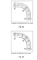
- curved flow passages such as (a) and (b) in Fig. 6 may be considered in order to explain the principle of the method for reducing shear stress applied to the heat insulator through application of the shear control ring suggested in the present invention.
- Fig. 6 is a drawing showing the fluid flow in curved flow passages depending on dam in shape tubes for designing shear control rings according to the present invention.
- FIG. 6 illustrates stream lines of fluid running in curved flow passages in which no dam is installed. According to basic hydrodynamic principles, it can be seen that fluid speed is radially constant in entrance points 1 of flow path, and exit point 3 of flow path. Since there is no obstacle which blocks flow, the fluid running in a pipe has stream lines which are parallel to the shape of flow passages in any points, as indicated with arrow lines in the pipe.
- a dam disturbing fluid flow is installed in the curved section in flow passages.
- the fluid speed in entrance points 1 and exit point 3 is radially constant same as the condition with no dam under the condition that there is enough distance.
- the stream line running in the pipe is not parallel to the shape of the flow passage and becomes twisted. Since the dam is installed inside the pipe, the dam is largely affected at a radially inward position while it is weakly affected at a radially outward position. That is, the radially-innermost dotted stream line is flowing through the most winding path and the stream line keeps the original shape in the outward direction.
- the speed of the radially-innermost fluid in curved section of flow path is increased by dam installment. That is, in case of flow path with no dam as shown in (a) of Fig. 6 , the speed gap (length of stream line) of the radially-innermost dotted stream line and the radially-outermost continuous (non-broken) stream line is big in point 2 and thus, the shear force is increased. However, in case of the dam installment as shown in (b) of Fig. 6 , the speed gap of point 2 is radially reduced by increase of speed (length of stream line) of the dotted stream line, and this reduces radial shear force of fluid applying to the side of the curved section.
- the shear control ring reduces differences of shear force(fluid speed) distributed in the heat insulator (fluid) between steel pipes and external pipes (flow path). Further, the difference reduction of radial shear force enables to reduce shear stress distributed in the heat insulator.
- Fig. 7 is a drawing comparing distribution of shearing stress of the heat insulator depending on shear control rings according to the present invention.
- (a) and (b) in Fig. 7 are the examples showing effects of the shear control ring, illustrating structure analysis of the maximum shear stress of the heat insulator depending on installment of shear control rings for 125A diameters.
- the maximum shear stress is radially generated inside (the part connected to the internal pipe), mainly formed in a thin area parallel to the curved shape of the bend.
- Fig. 8 is a drawing regarding detailed modeling of bend comprising shear control rings.
- number (A), height (B) and thickness (C) of the shear control ring are determined as factors and these are analyzed through three levels.
- the example of the applied shape is illustrated in Fig. 8 and application values generated on the basis of definitions and levels of factors, selected in Table 1, as below, are summarized.
- values depending on levels of each factor are selected, considering installable values in figure conditions of previous heat pipes.
- the height of the shear control ring is determined in consideration of restriction by shapes and sizes of the external pipe for each diameter.
- Table 3 summarizes the maximum shear stress and improvement rate of the bend specifications of optimum shear control ring suggested by the present specifications, applying foam pads, and the present invention. It is anticipated that the shear control ring has effects on strength improvement, reducing maximum shear stress of the heat insulator by 20% - 40% than the previous one.
- the shear control ring (140) having a diameter pressed in the external side of the internal pipe (110) is manufactured by cutting a hollow metal pipe or plate in accordance with the predesigned size with a cutter(5100).
- the shear control ring (140) is stuck by TIG welding after pressing the shear control ring in the curves (111) of the internal pipe (110) (S110). At this time, the curves (111) of the internal pipe (110) was preprocessed, and liquid penetrant non-destructive testing is further performed to check if there is a leakage after sticking the shear control ring (140).
- the internal pipe (110) attached to the shear control ring (140) is inserted and assembled to the external pipe (120) (S120).
- the external pipe (120) was already designed in the bent type to insert the internal pipe (110), and the spacer (113) and the leakage sensing line (123) are installed in the internal pipe (110).
- the heat insulator (130) is filled and foamed between the external pipe (120) and the internal pipe (110) (S130) .
Landscapes
- Engineering & Computer Science (AREA)
- General Engineering & Computer Science (AREA)
- Mechanical Engineering (AREA)
- Physics & Mathematics (AREA)
- Thermal Sciences (AREA)
- Chemical & Material Sciences (AREA)
- Combustion & Propulsion (AREA)
- Thermal Insulation (AREA)
- Rigid Pipes And Flexible Pipes (AREA)
- Pipe Accessories (AREA)
Priority Applications (1)
| Application Number | Priority Date | Filing Date | Title |
|---|---|---|---|
| PL11181781T PL2505902T3 (pl) | 2011-03-30 | 2011-09-19 | Rura kształtowana do rury grzewczej do ciepłownictwa posiadająca pierścień kontroli ścinania oraz sposób wytwarzania |
Applications Claiming Priority (1)
| Application Number | Priority Date | Filing Date | Title |
|---|---|---|---|
| KR1020110028810A KR101298656B1 (ko) | 2011-03-30 | 2011-03-30 | 전단제어링을 구비하는 지역난방 열배관용 이형관 |
Publications (3)
| Publication Number | Publication Date |
|---|---|
| EP2505902A2 true EP2505902A2 (de) | 2012-10-03 |
| EP2505902A3 EP2505902A3 (de) | 2013-08-28 |
| EP2505902B1 EP2505902B1 (de) | 2016-02-10 |
Family
ID=44785414
Family Applications (1)
| Application Number | Title | Priority Date | Filing Date |
|---|---|---|---|
| EP11181781.3A Not-in-force EP2505902B1 (de) | 2011-03-30 | 2011-09-19 | Formrohr für ein Fernwärmerohr mit Schersteuerungsring und Verfahren dafür |
Country Status (5)
| Country | Link |
|---|---|
| EP (1) | EP2505902B1 (de) |
| KR (1) | KR101298656B1 (de) |
| CN (1) | CN102734603B (de) |
| DK (1) | DK2505902T3 (de) |
| PL (1) | PL2505902T3 (de) |
Cited By (3)
| Publication number | Priority date | Publication date | Assignee | Title |
|---|---|---|---|---|
| CN103453281A (zh) * | 2013-01-04 | 2013-12-18 | 李宏江 | 一种普通保温软硬管道及其制造方法 |
| CN110472352A (zh) * | 2019-08-20 | 2019-11-19 | 大连海事大学 | 垂直状态下脉动热管的启动临界管径设计方法 |
| WO2019224423A1 (en) * | 2018-05-21 | 2019-11-28 | Valmet Technologies Oy | A coaxial heat transfer tube suitable for a fluidized bed boiler and a method for manufacturing same |
Families Citing this family (7)
| Publication number | Priority date | Publication date | Assignee | Title |
|---|---|---|---|---|
| CN103234098A (zh) * | 2013-05-14 | 2013-08-07 | 广西玉林宏江能源科技有限公司 | 普通保温软硬管道的制造方法 |
| CN104295845A (zh) * | 2014-09-26 | 2015-01-21 | 哈尔滨朗格斯特节能科技有限公司 | 智能预制直埋保温管交联聚乙烯工作管件弯头及制作方法 |
| CN104455877A (zh) * | 2014-10-08 | 2015-03-25 | 哈尔滨朗格斯特节能科技有限公司 | 智能预制直埋保温管交联聚乙烯双管管件弯头及制作方法 |
| CN104373730A (zh) * | 2014-10-31 | 2015-02-25 | 哈尔滨朗格斯特节能科技有限公司 | 智能预制直埋保温管双管弯头报警线固定装置及固定方法 |
| CA2981548A1 (en) * | 2015-04-09 | 2016-10-13 | Mrp Participacoes Eireli | Method for welding of insulated pipe |
| CN113414392B (zh) * | 2021-05-11 | 2023-02-17 | 岭东核电有限公司 | 基于3d打印技术的异型管道的制备方法 |
| CN117020590A (zh) * | 2023-10-08 | 2023-11-10 | 核工业西南物理研究院 | 一种带夹层的异型管的制造方法 |
Family Cites Families (11)
| Publication number | Priority date | Publication date | Assignee | Title |
|---|---|---|---|---|
| US2041911A (en) * | 1935-05-25 | 1936-05-26 | Universal Insulation Company | Heat insulation |
| SE434815B (sv) * | 1982-02-23 | 1984-08-20 | Lindab Nord Ab | Sett for framstellning av isolerade rorledningsdetaljer |
| DE3345371A1 (de) * | 1983-12-15 | 1985-06-27 | kabelmetal electro GmbH, 3000 Hannover | Verfahren zum nachisolieren eines bogens einer waermeisolierten rohrleitung |
| DE3506144A1 (de) * | 1985-02-22 | 1986-08-28 | kabelmetal electro GmbH, 3000 Hannover | Verfahren zur herstellung eines waermeisolierten leitungsrohres |
| US5031665A (en) * | 1989-01-31 | 1991-07-16 | Exxon Research And Engineering Company | Curved pipe section having refractory lining and central section of flexible insulating material |
| CN1067952A (zh) * | 1991-06-20 | 1993-01-13 | 广饶县稻庄镇散热器厂 | 玻璃钢夹克保温管道及其成型方法 |
| JP4899808B2 (ja) * | 2006-11-09 | 2012-03-21 | Jfeスチール株式会社 | 超電導送電用断熱多重管の曲管部 |
| KR100843341B1 (ko) * | 2007-12-05 | 2008-07-03 | 에스이피엔씨 주식회사 | 융착층을 갖는 이중보온관, 그 제조방법 및 제조장치 |
| JP5302036B2 (ja) * | 2009-02-10 | 2013-10-02 | 本田技研工業株式会社 | 円筒状ワーク切断装置 |
| CN101629912A (zh) * | 2009-08-10 | 2010-01-20 | 西部金属材料股份有限公司 | 一种钛钢复合板设备钛焊缝可靠性测定方法 |
| WO2011021882A2 (ko) * | 2009-08-21 | 2011-02-24 | Yu Hong Keun | 누설 유체 및 배관 절단 감지 장치 및 그 제조방법과 이를 적용한 배관 |
-
2011
- 2011-03-30 KR KR1020110028810A patent/KR101298656B1/ko active Active
- 2011-09-09 CN CN201110266878.6A patent/CN102734603B/zh not_active Expired - Fee Related
- 2011-09-19 DK DK11181781.3T patent/DK2505902T3/en active
- 2011-09-19 EP EP11181781.3A patent/EP2505902B1/de not_active Not-in-force
- 2011-09-19 PL PL11181781T patent/PL2505902T3/pl unknown
Non-Patent Citations (1)
| Title |
|---|
| None |
Cited By (5)
| Publication number | Priority date | Publication date | Assignee | Title |
|---|---|---|---|---|
| CN103453281A (zh) * | 2013-01-04 | 2013-12-18 | 李宏江 | 一种普通保温软硬管道及其制造方法 |
| WO2019224423A1 (en) * | 2018-05-21 | 2019-11-28 | Valmet Technologies Oy | A coaxial heat transfer tube suitable for a fluidized bed boiler and a method for manufacturing same |
| US11859911B2 (en) | 2018-05-21 | 2024-01-02 | Valmet Technologies Oy | Coaxial heat transfer tube suitable for a fluidized bed boiler and a method for manufacturing same |
| CN110472352A (zh) * | 2019-08-20 | 2019-11-19 | 大连海事大学 | 垂直状态下脉动热管的启动临界管径设计方法 |
| CN110472352B (zh) * | 2019-08-20 | 2022-10-25 | 大连海事大学 | 垂直状态下脉动热管的启动临界管径设计方法 |
Also Published As
| Publication number | Publication date |
|---|---|
| CN102734603B (zh) | 2014-10-08 |
| CN102734603A (zh) | 2012-10-17 |
| DK2505902T3 (en) | 2016-04-11 |
| KR20120110747A (ko) | 2012-10-10 |
| EP2505902B1 (de) | 2016-02-10 |
| KR101298656B1 (ko) | 2013-08-21 |
| EP2505902A3 (de) | 2013-08-28 |
| PL2505902T3 (pl) | 2016-08-31 |
Similar Documents
| Publication | Publication Date | Title |
|---|---|---|
| EP2505902A2 (de) | Formrohr für ein Abschnittsheizungsrohr mit Schersteuerungsring und Verfahren dafür | |
| CN102226487B (zh) | 一种基于逆流热交换原理的输热三层套管系统 | |
| KR100915630B1 (ko) | 배관용 단열커버 및 그 시공방법 | |
| CN204704478U (zh) | 基于t型截面变形元件的深水管中管止屈器 | |
| JP6703906B2 (ja) | 凍結工法 | |
| CN108612911B (zh) | 一种直埋式热力管道 | |
| CN201265827Y (zh) | 节能支架 | |
| CN204176132U (zh) | 基于cw型截面变形元件深水管中管止屈器 | |
| CN205745646U (zh) | 基于cx截面变形元件深水管中管止屈器 | |
| CN102296721A (zh) | 一种带套管单杆方钢管支撑及其构造方法 | |
| CN203348756U (zh) | 一种新型复合保温管道 | |
| US20160097566A1 (en) | Cooling system using deep seawater | |
| CN110778794A (zh) | 一种预制聚氨酯保温管用预装配式绝热滑动支座 | |
| CN111006072A (zh) | 一种带自补偿降应力高效绝热管托的热棒式管架 | |
| CN104896216A (zh) | 高密度聚乙烯波纹型外护管双管保温管道 | |
| CN204176133U (zh) | 基于齿状截面变形元件的深水管中管止屈器 | |
| US20070257124A1 (en) | Hydronic radiant flooring heating system | |
| JP2023509326A (ja) | スパイラルチューブ | |
| CN203488844U (zh) | 一种垂直保温管道导向支架 | |
| Kim et al. | Development of a reinforced bend with shear control ring for district heating | |
| CN203948137U (zh) | 用于三塔合一、两机一塔的循环水管道布置结构 | |
| CN220379215U (zh) | 混凝土中工艺冷却水预埋管道保温结构 | |
| KR102763289B1 (ko) | 건축물용 배관 진동 및 소음 방지구조체 | |
| CN219454293U (zh) | 一种地热利用装置 | |
| CN105443865B (zh) | 一种基于t型截面变形元件的深水管中管止屈器 |
Legal Events
| Date | Code | Title | Description |
|---|---|---|---|
| PUAI | Public reference made under article 153(3) epc to a published international application that has entered the european phase |
Free format text: ORIGINAL CODE: 0009012 |
|
| AK | Designated contracting states |
Kind code of ref document: A2 Designated state(s): AL AT BE BG CH CY CZ DE DK EE ES FI FR GB GR HR HU IE IS IT LI LT LU LV MC MK MT NL NO PL PT RO RS SE SI SK SM TR |
|
| AX | Request for extension of the european patent |
Extension state: BA ME |
|
| PUAL | Search report despatched |
Free format text: ORIGINAL CODE: 0009013 |
|
| AK | Designated contracting states |
Kind code of ref document: A3 Designated state(s): AL AT BE BG CH CY CZ DE DK EE ES FI FR GB GR HR HU IE IS IT LI LT LU LV MC MK MT NL NO PL PT RO RS SE SI SK SM TR |
|
| AX | Request for extension of the european patent |
Extension state: BA ME |
|
| RIC1 | Information provided on ipc code assigned before grant |
Ipc: F16L 59/22 20060101AFI20130724BHEP |
|
| 17P | Request for examination filed |
Effective date: 20140225 |
|
| RBV | Designated contracting states (corrected) |
Designated state(s): AL AT BE BG CH CY CZ DE DK EE ES FI FR GB GR HR HU IE IS IT LI LT LU LV MC MK MT NL NO PL PT RO RS SE SI SK SM TR |
|
| GRAP | Despatch of communication of intention to grant a patent |
Free format text: ORIGINAL CODE: EPIDOSNIGR1 |
|
| INTG | Intention to grant announced |
Effective date: 20150806 |
|
| GRAS | Grant fee paid |
Free format text: ORIGINAL CODE: EPIDOSNIGR3 |
|
| GRAA | (expected) grant |
Free format text: ORIGINAL CODE: 0009210 |
|
| AK | Designated contracting states |
Kind code of ref document: B1 Designated state(s): AL AT BE BG CH CY CZ DE DK EE ES FI FR GB GR HR HU IE IS IT LI LT LU LV MC MK MT NL NO PL PT RO RS SE SI SK SM TR |
|
| REG | Reference to a national code |
Ref country code: GB Ref legal event code: FG4D |
|
| REG | Reference to a national code |
Ref country code: AT Ref legal event code: REF Ref document number: 774827 Country of ref document: AT Kind code of ref document: T Effective date: 20160215 Ref country code: CH Ref legal event code: EP |
|
| REG | Reference to a national code |
Ref country code: IE Ref legal event code: FG4D |
|
| REG | Reference to a national code |
Ref country code: DE Ref legal event code: R096 Ref document number: 602011023193 Country of ref document: DE |
|
| REG | Reference to a national code |
Ref country code: DK Ref legal event code: T3 Effective date: 20160408 |
|
| REG | Reference to a national code |
Ref country code: SE Ref legal event code: TRGR |
|
| REG | Reference to a national code |
Ref country code: LT Ref legal event code: MG4D |
|
| REG | Reference to a national code |
Ref country code: NL Ref legal event code: MP Effective date: 20160210 |
|
| REG | Reference to a national code |
Ref country code: AT Ref legal event code: MK05 Ref document number: 774827 Country of ref document: AT Kind code of ref document: T Effective date: 20160210 |
|
| PG25 | Lapsed in a contracting state [announced via postgrant information from national office to epo] |
Ref country code: IT Free format text: LAPSE BECAUSE OF FAILURE TO SUBMIT A TRANSLATION OF THE DESCRIPTION OR TO PAY THE FEE WITHIN THE PRESCRIBED TIME-LIMIT Effective date: 20160210 Ref country code: NO Free format text: LAPSE BECAUSE OF FAILURE TO SUBMIT A TRANSLATION OF THE DESCRIPTION OR TO PAY THE FEE WITHIN THE PRESCRIBED TIME-LIMIT Effective date: 20160510 Ref country code: GR Free format text: LAPSE BECAUSE OF FAILURE TO SUBMIT A TRANSLATION OF THE DESCRIPTION OR TO PAY THE FEE WITHIN THE PRESCRIBED TIME-LIMIT Effective date: 20160511 Ref country code: ES Free format text: LAPSE BECAUSE OF FAILURE TO SUBMIT A TRANSLATION OF THE DESCRIPTION OR TO PAY THE FEE WITHIN THE PRESCRIBED TIME-LIMIT Effective date: 20160210 Ref country code: HR Free format text: LAPSE BECAUSE OF FAILURE TO SUBMIT A TRANSLATION OF THE DESCRIPTION OR TO PAY THE FEE WITHIN THE PRESCRIBED TIME-LIMIT Effective date: 20160210 |
|
| PG25 | Lapsed in a contracting state [announced via postgrant information from national office to epo] |
Ref country code: IS Free format text: LAPSE BECAUSE OF FAILURE TO SUBMIT A TRANSLATION OF THE DESCRIPTION OR TO PAY THE FEE WITHIN THE PRESCRIBED TIME-LIMIT Effective date: 20160610 Ref country code: NL Free format text: LAPSE BECAUSE OF FAILURE TO SUBMIT A TRANSLATION OF THE DESCRIPTION OR TO PAY THE FEE WITHIN THE PRESCRIBED TIME-LIMIT Effective date: 20160210 Ref country code: RS Free format text: LAPSE BECAUSE OF FAILURE TO SUBMIT A TRANSLATION OF THE DESCRIPTION OR TO PAY THE FEE WITHIN THE PRESCRIBED TIME-LIMIT Effective date: 20160210 Ref country code: AT Free format text: LAPSE BECAUSE OF FAILURE TO SUBMIT A TRANSLATION OF THE DESCRIPTION OR TO PAY THE FEE WITHIN THE PRESCRIBED TIME-LIMIT Effective date: 20160210 Ref country code: LV Free format text: LAPSE BECAUSE OF FAILURE TO SUBMIT A TRANSLATION OF THE DESCRIPTION OR TO PAY THE FEE WITHIN THE PRESCRIBED TIME-LIMIT Effective date: 20160210 Ref country code: PT Free format text: LAPSE BECAUSE OF FAILURE TO SUBMIT A TRANSLATION OF THE DESCRIPTION OR TO PAY THE FEE WITHIN THE PRESCRIBED TIME-LIMIT Effective date: 20160613 Ref country code: LT Free format text: LAPSE BECAUSE OF FAILURE TO SUBMIT A TRANSLATION OF THE DESCRIPTION OR TO PAY THE FEE WITHIN THE PRESCRIBED TIME-LIMIT Effective date: 20160210 |
|
| PG25 | Lapsed in a contracting state [announced via postgrant information from national office to epo] |
Ref country code: EE Free format text: LAPSE BECAUSE OF FAILURE TO SUBMIT A TRANSLATION OF THE DESCRIPTION OR TO PAY THE FEE WITHIN THE PRESCRIBED TIME-LIMIT Effective date: 20160210 |
|
| REG | Reference to a national code |
Ref country code: DE Ref legal event code: R097 Ref document number: 602011023193 Country of ref document: DE |
|
| PG25 | Lapsed in a contracting state [announced via postgrant information from national office to epo] |
Ref country code: SK Free format text: LAPSE BECAUSE OF FAILURE TO SUBMIT A TRANSLATION OF THE DESCRIPTION OR TO PAY THE FEE WITHIN THE PRESCRIBED TIME-LIMIT Effective date: 20160210 Ref country code: SM Free format text: LAPSE BECAUSE OF FAILURE TO SUBMIT A TRANSLATION OF THE DESCRIPTION OR TO PAY THE FEE WITHIN THE PRESCRIBED TIME-LIMIT Effective date: 20160210 Ref country code: RO Free format text: LAPSE BECAUSE OF FAILURE TO SUBMIT A TRANSLATION OF THE DESCRIPTION OR TO PAY THE FEE WITHIN THE PRESCRIBED TIME-LIMIT Effective date: 20160210 Ref country code: CZ Free format text: LAPSE BECAUSE OF FAILURE TO SUBMIT A TRANSLATION OF THE DESCRIPTION OR TO PAY THE FEE WITHIN THE PRESCRIBED TIME-LIMIT Effective date: 20160210 |
|
| PLBE | No opposition filed within time limit |
Free format text: ORIGINAL CODE: 0009261 |
|
| STAA | Information on the status of an ep patent application or granted ep patent |
Free format text: STATUS: NO OPPOSITION FILED WITHIN TIME LIMIT |
|
| PG25 | Lapsed in a contracting state [announced via postgrant information from national office to epo] |
Ref country code: BE Free format text: LAPSE BECAUSE OF FAILURE TO SUBMIT A TRANSLATION OF THE DESCRIPTION OR TO PAY THE FEE WITHIN THE PRESCRIBED TIME-LIMIT Effective date: 20160210 |
|
| 26N | No opposition filed |
Effective date: 20161111 |
|
| PG25 | Lapsed in a contracting state [announced via postgrant information from national office to epo] |
Ref country code: SI Free format text: LAPSE BECAUSE OF FAILURE TO SUBMIT A TRANSLATION OF THE DESCRIPTION OR TO PAY THE FEE WITHIN THE PRESCRIBED TIME-LIMIT Effective date: 20160210 Ref country code: BG Free format text: LAPSE BECAUSE OF FAILURE TO SUBMIT A TRANSLATION OF THE DESCRIPTION OR TO PAY THE FEE WITHIN THE PRESCRIBED TIME-LIMIT Effective date: 20160510 |
|
| PG25 | Lapsed in a contracting state [announced via postgrant information from national office to epo] |
Ref country code: MC Free format text: LAPSE BECAUSE OF FAILURE TO SUBMIT A TRANSLATION OF THE DESCRIPTION OR TO PAY THE FEE WITHIN THE PRESCRIBED TIME-LIMIT Effective date: 20160210 |
|
| REG | Reference to a national code |
Ref country code: CH Ref legal event code: PL |
|
| GBPC | Gb: european patent ceased through non-payment of renewal fee |
Effective date: 20160919 |
|
| REG | Reference to a national code |
Ref country code: IE Ref legal event code: MM4A |
|
| REG | Reference to a national code |
Ref country code: FR Ref legal event code: ST Effective date: 20170531 |
|
| PG25 | Lapsed in a contracting state [announced via postgrant information from national office to epo] |
Ref country code: IE Free format text: LAPSE BECAUSE OF NON-PAYMENT OF DUE FEES Effective date: 20160919 Ref country code: GB Free format text: LAPSE BECAUSE OF NON-PAYMENT OF DUE FEES Effective date: 20160919 Ref country code: CH Free format text: LAPSE BECAUSE OF NON-PAYMENT OF DUE FEES Effective date: 20160930 Ref country code: LI Free format text: LAPSE BECAUSE OF NON-PAYMENT OF DUE FEES Effective date: 20160930 Ref country code: FR Free format text: LAPSE BECAUSE OF NON-PAYMENT OF DUE FEES Effective date: 20160930 |
|
| PG25 | Lapsed in a contracting state [announced via postgrant information from national office to epo] |
Ref country code: LU Free format text: LAPSE BECAUSE OF NON-PAYMENT OF DUE FEES Effective date: 20160919 |
|
| REG | Reference to a national code |
Ref country code: DE Ref legal event code: R082 Ref document number: 602011023193 Country of ref document: DE Representative=s name: EISENFUEHR SPEISER PATENTANWAELTE RECHTSANWAEL, DE |
|
| PG25 | Lapsed in a contracting state [announced via postgrant information from national office to epo] |
Ref country code: CY Free format text: LAPSE BECAUSE OF FAILURE TO SUBMIT A TRANSLATION OF THE DESCRIPTION OR TO PAY THE FEE WITHIN THE PRESCRIBED TIME-LIMIT Effective date: 20160210 Ref country code: HU Free format text: LAPSE BECAUSE OF FAILURE TO SUBMIT A TRANSLATION OF THE DESCRIPTION OR TO PAY THE FEE WITHIN THE PRESCRIBED TIME-LIMIT; INVALID AB INITIO Effective date: 20110919 |
|
| PG25 | Lapsed in a contracting state [announced via postgrant information from national office to epo] |
Ref country code: MK Free format text: LAPSE BECAUSE OF FAILURE TO SUBMIT A TRANSLATION OF THE DESCRIPTION OR TO PAY THE FEE WITHIN THE PRESCRIBED TIME-LIMIT Effective date: 20160210 Ref country code: TR Free format text: LAPSE BECAUSE OF FAILURE TO SUBMIT A TRANSLATION OF THE DESCRIPTION OR TO PAY THE FEE WITHIN THE PRESCRIBED TIME-LIMIT Effective date: 20160210 Ref country code: MT Free format text: LAPSE BECAUSE OF NON-PAYMENT OF DUE FEES Effective date: 20160930 |
|
| PG25 | Lapsed in a contracting state [announced via postgrant information from national office to epo] |
Ref country code: AL Free format text: LAPSE BECAUSE OF FAILURE TO SUBMIT A TRANSLATION OF THE DESCRIPTION OR TO PAY THE FEE WITHIN THE PRESCRIBED TIME-LIMIT Effective date: 20160210 |
|
| PGFP | Annual fee paid to national office [announced via postgrant information from national office to epo] |
Ref country code: FI Payment date: 20210920 Year of fee payment: 11 |
|
| PGFP | Annual fee paid to national office [announced via postgrant information from national office to epo] |
Ref country code: DK Payment date: 20210921 Year of fee payment: 11 Ref country code: PL Payment date: 20210819 Year of fee payment: 11 Ref country code: SE Payment date: 20210921 Year of fee payment: 11 |
|
| PGFP | Annual fee paid to national office [announced via postgrant information from national office to epo] |
Ref country code: DE Payment date: 20211006 Year of fee payment: 11 |
|
| REG | Reference to a national code |
Ref country code: DE Ref legal event code: R119 Ref document number: 602011023193 Country of ref document: DE |
|
| PG25 | Lapsed in a contracting state [announced via postgrant information from national office to epo] |
Ref country code: FI Free format text: LAPSE BECAUSE OF NON-PAYMENT OF DUE FEES Effective date: 20220919 |
|
| REG | Reference to a national code |
Ref country code: DK Ref legal event code: EBP Effective date: 20220930 |
|
| REG | Reference to a national code |
Ref country code: SE Ref legal event code: EUG |
|
| PG25 | Lapsed in a contracting state [announced via postgrant information from national office to epo] |
Ref country code: DE Free format text: LAPSE BECAUSE OF NON-PAYMENT OF DUE FEES Effective date: 20230401 |
|
| PG25 | Lapsed in a contracting state [announced via postgrant information from national office to epo] |
Ref country code: SE Free format text: LAPSE BECAUSE OF NON-PAYMENT OF DUE FEES Effective date: 20220920 |
|
| PG25 | Lapsed in a contracting state [announced via postgrant information from national office to epo] |
Ref country code: DK Free format text: LAPSE BECAUSE OF NON-PAYMENT OF DUE FEES Effective date: 20220930 |
|
| PG25 | Lapsed in a contracting state [announced via postgrant information from national office to epo] |
Ref country code: PL Free format text: LAPSE BECAUSE OF NON-PAYMENT OF DUE FEES Effective date: 20220919 |