EP2505783A2 - Rotor of an axial compressor stage of a turbo machine - Google Patents
Rotor of an axial compressor stage of a turbo machine Download PDFInfo
- Publication number
- EP2505783A2 EP2505783A2 EP12161401A EP12161401A EP2505783A2 EP 2505783 A2 EP2505783 A2 EP 2505783A2 EP 12161401 A EP12161401 A EP 12161401A EP 12161401 A EP12161401 A EP 12161401A EP 2505783 A2 EP2505783 A2 EP 2505783A2
- Authority
- EP
- European Patent Office
- Prior art keywords
- blades
- blade ring
- rotor according
- blade
- rotor
- Prior art date
- Legal status (The legal status is an assumption and is not a legal conclusion. Google has not performed a legal analysis and makes no representation as to the accuracy of the status listed.)
- Granted
Links
Images


Classifications
-
- F—MECHANICAL ENGINEERING; LIGHTING; HEATING; WEAPONS; BLASTING
- F01—MACHINES OR ENGINES IN GENERAL; ENGINE PLANTS IN GENERAL; STEAM ENGINES
- F01D—NON-POSITIVE DISPLACEMENT MACHINES OR ENGINES, e.g. STEAM TURBINES
- F01D5/00—Blades; Blade-carrying members; Heating, heat-insulating, cooling or antivibration means on the blades or the members
- F01D5/12—Blades
- F01D5/14—Form or construction
- F01D5/141—Shape, i.e. outer, aerodynamic form
- F01D5/142—Shape, i.e. outer, aerodynamic form of the blades of successive rotor or stator blade-rows
- F01D5/143—Contour of the outer or inner working fluid flow path wall, i.e. shroud or hub contour
-
- F—MECHANICAL ENGINEERING; LIGHTING; HEATING; WEAPONS; BLASTING
- F01—MACHINES OR ENGINES IN GENERAL; ENGINE PLANTS IN GENERAL; STEAM ENGINES
- F01D—NON-POSITIVE DISPLACEMENT MACHINES OR ENGINES, e.g. STEAM TURBINES
- F01D5/00—Blades; Blade-carrying members; Heating, heat-insulating, cooling or antivibration means on the blades or the members
- F01D5/02—Blade-carrying members, e.g. rotors
- F01D5/10—Anti- vibration means
-
- F—MECHANICAL ENGINEERING; LIGHTING; HEATING; WEAPONS; BLASTING
- F01—MACHINES OR ENGINES IN GENERAL; ENGINE PLANTS IN GENERAL; STEAM ENGINES
- F01D—NON-POSITIVE DISPLACEMENT MACHINES OR ENGINES, e.g. STEAM TURBINES
- F01D5/00—Blades; Blade-carrying members; Heating, heat-insulating, cooling or antivibration means on the blades or the members
- F01D5/34—Rotor-blade aggregates of unitary construction, e.g. formed of sheet laminae
-
- F—MECHANICAL ENGINEERING; LIGHTING; HEATING; WEAPONS; BLASTING
- F05—INDEXING SCHEMES RELATING TO ENGINES OR PUMPS IN VARIOUS SUBCLASSES OF CLASSES F01-F04
- F05D—INDEXING SCHEME FOR ASPECTS RELATING TO NON-POSITIVE-DISPLACEMENT MACHINES OR ENGINES, GAS-TURBINES OR JET-PROPULSION PLANTS
- F05D2240/00—Components
- F05D2240/80—Platforms for stationary or moving blades
-
- F—MECHANICAL ENGINEERING; LIGHTING; HEATING; WEAPONS; BLASTING
- F05—INDEXING SCHEMES RELATING TO ENGINES OR PUMPS IN VARIOUS SUBCLASSES OF CLASSES F01-F04
- F05D—INDEXING SCHEME FOR ASPECTS RELATING TO NON-POSITIVE-DISPLACEMENT MACHINES OR ENGINES, GAS-TURBINES OR JET-PROPULSION PLANTS
- F05D2250/00—Geometry
- F05D2250/70—Shape
- F05D2250/71—Shape curved
- F05D2250/711—Shape curved convex
-
- F—MECHANICAL ENGINEERING; LIGHTING; HEATING; WEAPONS; BLASTING
- F05—INDEXING SCHEMES RELATING TO ENGINES OR PUMPS IN VARIOUS SUBCLASSES OF CLASSES F01-F04
- F05D—INDEXING SCHEME FOR ASPECTS RELATING TO NON-POSITIVE-DISPLACEMENT MACHINES OR ENGINES, GAS-TURBINES OR JET-PROPULSION PLANTS
- F05D2250/00—Geometry
- F05D2250/70—Shape
- F05D2250/71—Shape curved
- F05D2250/713—Shape curved inflexed
-
- F—MECHANICAL ENGINEERING; LIGHTING; HEATING; WEAPONS; BLASTING
- F05—INDEXING SCHEMES RELATING TO ENGINES OR PUMPS IN VARIOUS SUBCLASSES OF CLASSES F01-F04
- F05D—INDEXING SCHEME FOR ASPECTS RELATING TO NON-POSITIVE-DISPLACEMENT MACHINES OR ENGINES, GAS-TURBINES OR JET-PROPULSION PLANTS
- F05D2250/00—Geometry
- F05D2250/70—Shape
- F05D2250/73—Shape asymmetric
-
- F—MECHANICAL ENGINEERING; LIGHTING; HEATING; WEAPONS; BLASTING
- F05—INDEXING SCHEMES RELATING TO ENGINES OR PUMPS IN VARIOUS SUBCLASSES OF CLASSES F01-F04
- F05D—INDEXING SCHEME FOR ASPECTS RELATING TO NON-POSITIVE-DISPLACEMENT MACHINES OR ENGINES, GAS-TURBINES OR JET-PROPULSION PLANTS
- F05D2260/00—Function
- F05D2260/96—Preventing, counteracting or reducing vibration or noise
-
- Y—GENERAL TAGGING OF NEW TECHNOLOGICAL DEVELOPMENTS; GENERAL TAGGING OF CROSS-SECTIONAL TECHNOLOGIES SPANNING OVER SEVERAL SECTIONS OF THE IPC; TECHNICAL SUBJECTS COVERED BY FORMER USPC CROSS-REFERENCE ART COLLECTIONS [XRACs] AND DIGESTS
- Y02—TECHNOLOGIES OR APPLICATIONS FOR MITIGATION OR ADAPTATION AGAINST CLIMATE CHANGE
- Y02T—CLIMATE CHANGE MITIGATION TECHNOLOGIES RELATED TO TRANSPORTATION
- Y02T50/00—Aeronautics or air transport
- Y02T50/60—Efficient propulsion technologies, e.g. for aircraft
Abstract
Description
Die Erfindung betrifft einen Rotor einer Axialverdichterstufe einer Turbomaschine. Derartige Rotoren werden beispielsweise in Strahltriebwerken eingesetzt.The invention relates to a rotor of an axial compressor stage of a turbomachine. Such rotors are used for example in jet engines.
Axialverdichter bestehen üblicherweise aus einer Mehrzahl von Verdichterstufen, die jeweils einen Rotor und einen Stator umfassen, die unmittelbar hintereinander geschaltet sind. An dem Rotor sind eine Vielzahl von aerodynamisch geformten Körpern angeordnet, die als Laufschaufeln bezeichnet werden. Ebenso sind an dem Stator eine Vielzahl aerodynamisch geformter Körper angeordnet, die als Leitschaufeln bezeichnet werden. Die Laufschaufeln und die Leitschaufeln befinden alternierend sich in einem Strömungskanal des Verdichters.Axial compressors usually consist of a plurality of compressor stages, each comprising a rotor and a stator, which are connected directly one behind the other. Arranged on the rotor are a plurality of aerodynamically shaped bodies, which are referred to as moving blades. Similarly, a plurality of aerodynamically shaped bodies are arranged on the stator, which are referred to as guide vanes. The blades and the vanes are alternately located in a flow channel of the compressor.
Aus der Druckschrift
Es besteht ein Bedarf nach technischen Lösungen, die die Strömung im Schaufelkanal zwischen jeweils zwei Laufschaufeln eines Rotors verbessern. Insbesondere ist es anzustreben, ungünstige Schwingungsmoden von Drehkörper und Laufschaufeln eines Rotors zu reduzieren und dadurch eine Schaufelanregung abzuschwächen.There is a need for technical solutions that improve the flow in the blade channel between every two blades of a rotor. In particular, it is desirable to reduce adverse vibration modes of rotor and rotor blades of a rotor and thereby attenuate vane excitation.
Die Lehre des Anspruchs 1 sieht hierzu vor, dass bei einem Rotor mit einem Drehkörper, der an seinem Umfang einen Schaufelkranz mit einer radial außen liegenden Kranzoberfläche ausbildet, die Kranzoberfläche zwischen zwei benachbarten Laufschaufeln zumindest in einem Teilbereich sowohl in axialer Richtung als auch in Umfangsrichtung einen sich verändernden Radius bezogen auf die Drehachse des Drehkörpers aufweist.The teaching of
Die erfindungsgemäße Lösung sieht somit vor, die Fläche zwischen zwei Laufschaufeln dreidimensional zu konturieren. Insbesondere ist vorgesehen, dass sich der Radius der Kranzoberfläche sowohl in axialer Richtung (d.h. in Strömungsrichtung) als auch in Umfangsrichtung des Rotors verändert. Dies bedeutet, dass - in zumindest einem Teilbereich der Kranzoberfläche - benachbarte Punkte der Kranzoberfläche sowohl in Umfangsrichtung als auch in axialer Richtung einen unterschiedlichen Abstand zur Drehachse des Drehkörpers aufweisen.The solution according to the invention thus provides for three-dimensionally contouring the area between two moving blades. In particular, it is provided that the radius of the rim surface changes both in the axial direction (i.e., in the flow direction) and in the circumferential direction of the rotor. This means that - in at least a portion of the rim surface - adjacent points of the rim surface both in the circumferential direction and in the axial direction have a different distance from the axis of rotation of the rotary body.
Die erfindungsgemäße dreidimensionale Konturierung der Kranzoberfläche lässt im Stand der Technik vorherrschende Symmetrieeinschränkungen in der Gestaltung der Kranzoberfläche hinter sich. Hierdurch ergeben sich neue Freiheitsgrade in der Gestaltung der Kranzoberfläche, die es erlauben, die Strömung im Schaufelkanal günstig zu beeinflussen. Dabei können durch die dreidimensionale Konturierung der Kranzoberfläche ungünstige Schwingungsmoden des Drehkörpers, der in einer Ausführungsvariante als Scheibe oder beschaufelte Scheibe (BLISK = "Bladed Disk") ausgebildet ist, vermindert oder sogar unterdrückt werden. Ebenso kann eine Belastung aus gekoppelten Schwingungsmoden des Drehkörpers mit den Laufrädern vermindert werden, so dass insgesamt die Schaufelanregung abgeschwächt werden kann.The three-dimensional contouring of the rim surface according to the invention leaves behind prevailing symmetry restrictions in the design of the rim surface in the prior art. This results in new degrees of freedom in the design of the rim surface, which allow to influence the flow in the blade channel low. In this case, can be reduced or even suppressed by the three-dimensional contouring of the rim surface unfavorable vibration modes of the rotary body, which is designed in a variant as a disc or bladed disk (BLISK = "Bladed Disk"), or even suppressed. Likewise, a load of coupled vibration modes of the rotary body can be reduced with the wheels, so that overall the blade excitation can be attenuated.
Damit ermöglicht es die erfindungsgemäße Lösung, bei gleicher Verdichterauslegung die Höchstbelastung der Verdichterschaufeln zu reduzieren und in einer Ausführungsvariante den Bereich höchster Spannung an den Laufrädern auf der Druckseite und der Saugseite gleichmäßig zu verteilen, und zwar ohne die Notwendigkeit eines Kippens der Schaufeln (sogenanntes "blade lean"). Die Erfindung stellt ein optimiertes Design mit geringerem Gewicht und potentiell längerer Lebensdauer bereit. Erfindungsgemäße Rotoren können jedenfalls bei Nutzen der BLISK-Technologie ohne Mehrkosten hergestellt werden, da die Rotoren ohnehin aus dem Vollen gefertigt sind. So kann die Kranzoberfläche ohne fertigungstechnischen Mehraufwand eine dreidimensionale Konturierung erfahren.Thus, the solution according to the invention makes it possible, with the same compressor design, to reduce the maximum load on the compressor blades and, in one embodiment, evenly distribute the region of highest tension on the impellers on the pressure side and on the suction side, without the necessity of tilting the blades (so-called blade lean "). The invention provides an optimized design with lower weight and potentially longer life. In any case, rotors according to the invention can be produced at no extra cost using the BLISK technology, since the rotors are already made from solid. Thus, the rim surface can experience a three-dimensional contouring without manufacturing overhead.
Es wird darauf hingewiesen, dass die dreidimensionale Konturierung der Kranzoberfläche im Bereich einer auf dem Drehkörper angeordneten oder ausgebildeten Laufschaufel naturgemäß unterbrochen ist, da in diesem Bereich die Laufschaufel angeordnet ist. Der Übergang zwischen der Kranzoberfläche und den Laufschaufeln kann dabei im mathematischen Sinne unstetig (als Kante) oder stetig (unter Realisierung eines Ausrundungsradius) ausgebildet sein. Eventuell vorhandene Übergangsbereiche, die einen Ausrundungsradius zwischen der Kranzoberfläche und einer Laufschaufel realisieren, stellen dabei im Sinne der vorliegenden Erfindung einen Teilbereich der Laufschaufel dar, und nicht einen Teilbereich der Kranzoberfläche. Da solche Übergangsbereiche einen definierten Ausrundungsradius aufweisen, sind sie eindeutig von der Kranzoberfläche unterscheidbar. Als Kranzoberfläche im Sinne der vorliegenden Erfindung werden somit Oberflächenbereiche eines Schaufelkranzes axial vor und/oder axial hinter und/oder in Umfangsrichtung zwischen den Laufschaufeln bezeichnet, nicht jedoch die Laufschaufeln selbst und Übergangsbereiche zu den Laufschaufeln.It should be noted that the three-dimensional contouring of the rim surface in the region of a rotor blade arranged or formed on the rotary body is naturally interrupted, since the rotor blade is arranged in this region. The transition between the rim surface and the blades can be formed discontinuously in the mathematical sense (as an edge) or continuously (with the realization of a fillet radius). Possibly present transition regions that realize a fillet radius between the rim surface and a blade, in the context of the present invention constitute a partial region of the blade, and not a portion of the rim surface. Since such transition regions have a defined radius of curvature, they are clearly distinguishable from the rim surface. As a ring surface in the context of the present invention, surface areas of a blade ring axially before and / or axially behind and / or in the circumferential direction between the blades are therefore designated, but not the blades themselves and transition areas to the blades.
Weiter wird vorsorglich darauf hingewiesen, dass die erfindungsgemäße Änderung des Radius sowohl in axialer Richtung als auch in Umfangsrichtung derart stark ausgebildet ist, dass sie außerhalb des Toleranzbereiches einer Oberflächenbearbeitung liegt. Die erfindungsgemäße Konturierung stellt eine strömungsbeeinflussende dreidimensionale Konturierung der Kranzoberfläche bereit.As a precaution, it should also be pointed out that the change according to the invention of the radius in both the axial direction and in the circumferential direction is so strong that it lies outside the tolerance range of a surface treatment. The contouring according to the invention provides a flow-influencing three-dimensional contouring of the rim surface.
In einer Ausgestaltung der Erfindung ist vorgesehen, dass für zumindest einen Schnitt durch den Schaufelkranz in einer Ebene senkrecht zur Drehachse des Drehkörpers gilt, dass die resultierende Oberflächenlinie zwischen zwei Laufschaufeln zumindest abschnittsweise einen sich stetig verändernden Radius aufweist. Wenn man ein Zylinderkoordinatensystem betrachtet mit den drei Koordinaten a) Umfangswinkel (Φ), b) Abstand (r) von der Drehachse und c) Koordinate in axialer Richtung (x), so entspricht ein Schnitt durch den Schaufelkranz in einer Ebene senkrecht zur Drehachse des Drehkörpers einem Schnitt durch die Kranzoberfläche bei einem festen axialen Wert (x). Bei der genannten Erfindungsvariante gilt mit anderen Worten, dass sich bei der Oberflächenlinie der Radius (r) zwischen zwei Laufschaufeln in Abhängigkeit von Umfangswinkel (Φ) stetig ändert. Ein solcher Verlauf in Umfangsrichtung gilt für zumindest einige axiale Werte (x) und in einer Ausgestaltung für alle axialen Werte (x), also für die gesamte Kranzoberfläche.In one embodiment of the invention, it is provided that for at least one section through the blade ring in a plane perpendicular to the axis of rotation of the rotary body that the resulting surface line between two blades at least partially has a steadily changing radius. If one considers a cylindrical coordinate system with the three coordinates a) circumferential angle (Φ), b) distance (r) from the axis of rotation and c) coordinate in the axial direction (x), then a section through the blade ring corresponds in a plane perpendicular to the axis of rotation of the Rotary body a section through the rim surface at a fixed axial value (x). In other words, in the case of the abovementioned variant of the invention, the radius (r) between two moving blades depends on the surface line Circumferential angle (Φ) changes constantly. Such a course in the circumferential direction is valid for at least some axial values (x) and in one embodiment for all axial values (x), ie for the entire rim surface.
In einer weiteren Ausgestaltung der Erfindung ist vorgesehen, dass für zumindest einen Schnitt durch den Schaufelkranz in einer Ebene senkrecht zur Drehachse des Drehkörpers gilt, dass die resultierende Oberflächenlinie im Bereich zwischen zwei Laufschaufeln asymmetrisch ist. Ein symmetrischer Verlauf in Umfangsrichtung zwischen zwei Laufschaufeln wird bei dieser Ausführungsvariante aufgegeben, mit der Folge einer größeren Designfreiheit. Dass das genannte Merkmal für zumindest einen Schnitt gelten soll, bedeutet dabei, dass es für einen der möglichen Schnitte, eine Minderzahl der möglichen Schnitte, eine Mehrzahl der möglichen Schnitte oder alle Schnitte gilt, wobei angenommen wird, dass zwei Schnitte identisch sind, solange sie nicht einen Mindestabstand zueinander aufweisen.In a further embodiment of the invention, it is provided that for at least one section through the blade ring in a plane perpendicular to the axis of rotation of the rotary body, the resulting surface line in the area between two rotor blades is asymmetrical. A symmetrical course in the circumferential direction between two blades is abandoned in this embodiment, with the result of greater design freedom. The fact that the said feature is to apply to at least one cut means that it applies to one of the possible cuts, a minority of the possible cuts, a plurality of the possible cuts or all cuts, assuming that two cuts are identical as long as they are do not have a minimum distance from each other.
In einer Ausführungsvariante hierzu ist vorgesehen, dass die Kranzoberfläche angrenzend an die Saugseite der einen Laufschaufel höhere Radien aufweist als angrenzend an die Druckseite der anderen, benachbarten Laufschaufel. An der Saugseite ist somit eine konvexe Erhöhung bzw. ein Berg realisiert, während an der Druckseite eine konvexe Vertiefung bzw. ein Tal realisiert ist. Hierdurch kann in einer Ausführungsvariante erreicht werden, dass Spannungen auf der Druckseite und der Saugseite gleichmäßiger verteilt werden.In one embodiment, it is provided that the rim surface adjacent to the suction side of the one blade has higher radii than adjacent to the pressure side of the other, adjacent blade. On the suction side thus a convex elevation or a mountain is realized, while on the pressure side a convex depression or a valley is realized. As a result, it can be achieved in one embodiment that stresses on the pressure side and the suction side are distributed more uniformly.
In einer weiteren Ausführungsvariante ist vorgesehen, dass für zumindest einen Schnitt durch den Schaufelkranz in einer Ebene senkrecht zur Drehachse des Drehkörpers gilt, dass die resultierende Oberflächenlinie zwischen zwei Laufschaufeln in zumindest einem Abschnitt konvex gewölbt ist. Es ist somit zumindest in einem Teilbereich der Kranzoberfläche ein Berg zwischen zwei benachbarten Laufschaufeln gebildet.In a further embodiment variant, it is provided that for at least one section through the blade ring in a plane perpendicular to the axis of rotation of the rotary body, the resulting surface line between two rotor blades is convexly curved in at least one section. Thus, at least in a partial region of the rim surface, a mountain is formed between two adjacent rotor blades.
Eine Variation des Radius der Kranzoberfläche findet erfindungsgemäß auch in axialer Richtung statt. Im Folgenden werden einige Ausführungsbeispiele für eine entsprechende Oberflächenkonturierung in axialer Richtung betrachtet. Dabei wird jeweils ein Längsschnitt durch den Schaufelkranz und die dabei entstehende Oberflächenlinie zwischen einer axial vorderen Stirnseite und einer axial hinteren Stirnseite des Schaufelkranzes betrachtet. Ein solcher Längsschnitt entspricht bei einer Betrachtung in Zylinderkoordinaten einem Schnitt bei konstantem oder im wesentlichen konstanten Umfangswinkel (Φ). Die axial vordere Stirnseite kann auch als Schaufelvorderkante und die axial hintere Stirnseite als Schaufelhinterkante des Schaufelkranzes bezeichnet werden. Die Begriffe "vordere" und "hintere" beziehen sich auf die Strömungsrichtung.A variation of the radius of the rim surface according to the invention also takes place in the axial direction. In the following, some embodiments for a corresponding surface contouring in the axial direction are considered. In each case, a longitudinal section through the blade ring and the resulting surface line between an axially front end side and an axially rear end face of the blade ring is considered. When viewed in cylindrical coordinates, such a longitudinal section corresponds to a section at a constant or essentially constant circumferential angle (Φ). The axial front end can also be used as Blade leading edge and the axially rear end face be referred to as the blade trailing edge of the blade ring. The terms "front" and "rear" refer to the direction of flow.
In einer Ausgestaltung ist vorgesehen, dass die resultierende Oberflächenlinie zwischen einer vorderen Stirnseite und einer axial hinteren Stirnseite zumindest abschnittsweise einen sich stetig verändernden Radius aufweist.In one embodiment, it is provided that the resulting surface line between a front end side and an axially rear end side at least in sections has a steadily changing radius.
In einer weiteren Ausgestaltung ist vorgesehen, dass die resultierende Oberflächenlinie zwischen einer vorderen Stirnseite und einer axial hinteren Stirnseite in zumindest einem Abschnitt konvex gewölbt, also als Berg ausgeführt ist. Eine Ausführungsvariante hierzu sieht vor, dass die Oberflächenlinie in Richtung der Schaufelhinterkante zunächst ein Minimum und anschließend einen Maximum durchläuft. Für die Kranzoberfläche bedeutet dies, dass diese in Richtung der Schaufelhinterkante zunächst ein Tal und anschließend einen Berg durchläuft. Hierdurch wird der Gasstrom in günstiger Weise in den Schaufelkanal hinein eingeleitet.In a further embodiment, it is provided that the resulting surface line between a front end side and an axially rear end side in at least a portion convex, so it is designed as a mountain. A variant for this purpose provides that the surface line in the direction of the blade trailing edge initially passes through a minimum and then a maximum. For the rim surface, this means that it first passes through a valley and then a mountain in the direction of the blade trailing edge. As a result, the gas stream is introduced into the blade channel in a favorable manner.
Die erfindungsgemäße dreidimensionale Gestaltung, die auf Symmetrien im Bereich der Oberflächengestaltung zwischen zwei Laufschaufeln verzichtet, erlaubt grundsätzlich eine beliebig große Anzahl an Freiheitsgraden für die Oberflächengestaltung. In einer Ausgestaltung der Erfindung ist vorgesehen, dass diese große Anzahl reduziert wird, indem eine erste Oberflächenlinie eines ersten Schnitts durch den Schaufelkranz in einer Ebene senkrecht zur Drehachse des Drehkörpers einer Sinusfunktion, einer Kosinusfunktion, oder einer Kombination von Sinus- und Kosinusfunktionen gehorcht. Mindestens eine zweite Oberflächenlinie eines zum ersten Schnitt benachbarten zweiten Schnitts durch den Schaufelkranz gehorcht der gleichen Funktion, wobei jedoch eine andere Phasenlage gegenüber der ersten Oberflächenlinie vorgesehen ist.The three-dimensional design according to the invention, which dispenses with symmetries in the area of the surface design between two blades, fundamentally permits an arbitrarily large number of degrees of freedom for the surface design. In one embodiment of the invention, it is provided that this large number is reduced by obeying a first surface line of a first cut through the blade ring in a plane perpendicular to the rotational axis of the rotating body of a sine function, a cosine function, or a combination of sine and cosine functions. At least a second surface line of a second cut adjacent the first cut by the blade ring obeys the same function, but with a different phase position from the first surface line.
Mit anderen Worten weist jeder Schnitt durch die Kranzoberfläche, der in einer Ebene senkrecht zur Drehachse des Drehkörpers liegt, eine Oberflächenlinie auf, die durch eine oder mehrere Sinus- oder Kosinusfunktionen oder deren Kombination definiert wird. Bei Schnitten durch die Kranzoberfläche, die bei anderen axialen Werten (x) erfolgen, liegen die gleichen trigonometrischen Funktionen vor. Lediglich die Phasenlage und/oder die Amplitude wird in Abhängigkeit von der axialen Position (x) variiert. Hierdurch wird die Anzahl der Freiheitsgrade verringert, in einer Ausgestaltung auf 2 bis 5. Dies erlaubt beispielsweise eine vergleichsweise einfachere Programmierung einer Zerspanungsmaschine, mit deren Hilfe eine BLISK computergesteuert aus dem Vollen gefertigt wird.In other words, each section through the rim surface, which lies in a plane perpendicular to the rotation axis of the rotating body, has a surface line defined by one or more sine or cosine functions or their combination. In the case of cuts through the rim surface, which occur at other axial values (x), the same trigonometric functions are present. Only the phase angle and / or the amplitude is varied as a function of the axial position (x). This reduces the number of degrees of freedom, in one embodiment to 2 to 5. This allows, for example, a comparatively simpler programming of a Cutting machine, with the help of which a BLISK is computer-controlled made from scratch.
Gemäß einer weiteren Ausführungsvariante ist die Kranzoberfläche an der axial vorderen und/oder der axial hinteren Stirnseite des Schaufelkranzes durchgehend kreisförmig ausgebildet. An der Eintrittsseite und/oder der Austrittsseite des Schaufelkranzes wird ein kreisförmiger Rand mit festem Radius bereitgestellt. Die dreidimensionale Konturierung flacht sich dementsprechend zu den Stirnseiten des Schaufelkranzes hin aus. Hierdurch wird ein verlustfreier Übergang von einer Schaufelreihe zu einer angrenzenden Schaufelreihe bereitgestellt.According to a further embodiment, the rim surface is formed on the axially front and / or the axially rear end face of the blade ring continuously circular. At the entrance side and / or the exit side of the blade ring, a circular rim of fixed radius is provided. The three-dimensional contouring accordingly flattens out towards the end faces of the blade ring. This provides a lossless transition from one row of blades to an adjacent row of blades.
Es ist in einer Ausgestaltung der Erfindung vorgesehen, dass die Kranzoberfläche zwischen sämtlichen Laufschaufeln des Rotors jeweils die gleiche dreidimensionale Form aufweist. Die Anordnung ist symmetrisch in Bezug auf eine Drehung um einen Winkel, der dem Abstand zwischen zwei Laufschaufeln entspricht.It is provided in one embodiment of the invention that the rim surface between each rotor blades each having the same three-dimensional shape. The arrangement is symmetrical with respect to rotation through an angle equal to the distance between two blades.
Der betrachtete Drehkörper kann beispielsweise als Scheibe oder als Trommel ausgebildet sein. In einer Ausführungsvariante ist er, wie bereits erwähnt, in BLISK Technologie ausgeführt.The considered rotary body can be designed, for example, as a disk or as a drum. In one embodiment, it is, as already mentioned, executed in BLISK technology.
Die Erfindung wird nachfolgend unter Bezugnahme auf die Figuren der Zeichnung anhand mehrerer Ausführungsbeispiele näher erläutert. Es zeigen:
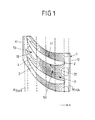
Figur 1- eine Draufsicht in radialer Richtung auf einen Teilbereich eines Rotors, der einen Schaufelkranz mit einer dreidimensional konturierten Kranzoberfläche aufweist;
Figur 2- eine perspektivische Ansicht eines weiteren Ausführungsbeispiels eines Rotors, der einen Schaufelkranz mit einer dreidimensional konturierten Kranzoberfläche aufweist;
- Figur 3A
- schematisch eine Ansicht in Strömungsrichtung auf einen Schnitt quer zur Drehachse durch einen Rotor mit einer dreidimensional konturierten Kranzoberfläche, wobei die Radiusvariation der Kranzoberfläche dargestellt ist;
- Figur 3B
- schematisch einen Längsschnitt durch einen Schaufelkranz mit einer dreidimensional konturierten Kranzoberfläche;
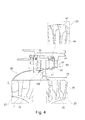
Figur 4- einen Längsschnitt durch ein Ausführungsbeispiel eines Verdichters eines Strahltriebwerks, wobei dreidimensional konturierte Flächen zum einen am Rotor und zum anderen am Stator des Verdichters dargestellt sind;
- Figur 5
- eine teilweise geschnittene Seitenansicht einer auf dem Schaufelkranz einer BLISK angeordneten Laufschaufel, wobei die Spannungsverteilung an der Laufschaufel und dem Schaufelkranz dargestellt ist;
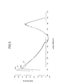
Figur 6- ein erstes Diagramm, das die mechanische Spannung an der Außenkante der Druckseite der Schaufel eines erfindungsgemäß ausgeführten Rotors im Vergleich zu einem konventionell ausgeführten Rotor zeigt; und
Figur 7- ein zweites Diagramm, das die mechanische Spannung an der Außenkante der Saugseite der Schaufel eines erfindungsgemäß ausgeführten Rotors im Vergleich zu einem konventionell ausgeführten Rotor zeigt.
- FIG. 1
- a plan view in the radial direction of a portion of a rotor having a blade ring with a three-dimensionally contoured rim surface;
- FIG. 2
- a perspective view of another embodiment of a rotor having a blade ring with a three-dimensionally contoured ring surface;
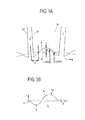
- FIG. 3A
- FIG. 2 schematically shows a view in the flow direction on a section transverse to the axis of rotation through a rotor with a three-dimensionally contoured rim surface, wherein the radius variation of the rim surface is shown; FIG.
- FIG. 3B
- schematically a longitudinal section through a blade ring with a three-dimensionally contoured ring surface;
- FIG. 4
- a longitudinal section through an embodiment of a compressor of a jet engine, wherein three-dimensionally contoured surfaces are shown on the one hand on the rotor and the other on the stator of the compressor;
- FIG. 5
- a partially sectioned side view of a arranged on the blade ring of a BLISK blade, the stress distribution on the blade and the blade ring is shown;
- FIG. 6
- a first diagram showing the mechanical stress on the outer edge of the pressure side of the blade of a rotor according to the invention in comparison with a conventionally designed rotor; and
- FIG. 7
- a second diagram showing the mechanical stress on the outer edge of the suction side of the blade of a rotor designed according to the invention in comparison with a conventionally designed rotor.
Die
Jede Laufschaufel 2 weist eine Saugseite 21 und eine Druckseite 22 auf. Der Schaufelkanal 3 zwischen zwei Laufschaufeln 2 wird seitlich begrenzt durch die Saugseite 21 der einen Laufschaufel 2 und die Druckseite 22 der anderen Laufschaufel 2. In radialer Richtung wird der Schaufelkanal 3 radial innen durch die Kranzoberfläche 10 und radial außen durch die Oberfläche eines nicht dargestellten Gehäuses begrenzt.Each
Die Kranzoberfläche 10 ist dreidimensional konturiert ist, d. h. sie weist sich verändernde Radien sowohl in axialer als auch in Umfangsrichtung auf. Die Radiusänderung ist stetig im mathematischen Sinne, d. h. sie weist keine Sprungstellen auf. Die dreidimensionale Konturierung ist durch in der
Aus der Darstellung der Höhenlinien 4 ergibt sich, dass die Kranzoberfläche in axialer Richtung x (und dabei der Wölbung der Laufschaufeln 2 folgend) zunächst eine konkave Einbuchtung bzw. ein Tal 51 und anschließend eine konvexe Erhebung bzw. einen Berg 52 durchläuft. Auch ist zu erkennen, dass die Konturierung in Umfangsrichtung zwischen zwei Laufschaufeln 2 nicht symmetrisch ist. Insbesondere befindet sich der Berg 52 näher an der Druckseite 22 der jeweiligen Laufschaufel 2 als an der Saugseite 21.From the illustration of the
Weiter ist in der
Ein kreisförmiger Rand mit konstantem Radius an der axial vorderen Stirnseite 11 und an der axial hinteren Stirnseite 12 ist dabei in einer Ausgestaltung der Erfindung, jedoch nicht notwendigerweise, realisiert, um einen möglichst verlustfreien Übergang von einer Schaufelreihe auf die nächste Schaufelreihe sicherzustellen.A circular edge with a constant radius at the axially
Die
Auch bei der dreidimensionalen Oberflächenkonturierung der
Die dargestellte Konturierung mit einer konkaven Vertiefung 51 am Anfang des durch jeweils zwei Laufschaufeln 2 gebildeten Schaufelkanals und einer konvexen Erhöhung 52, die sich in axialer Richtung hinter der Vertiefung 51 befindet, verbessert die Strömung im Schaufelkanal, da die einströmende Luft mittels der Vertiefung 51 am Anfang des Schaufelkanals verlustarm in diesen einströmen kann. Zusätzlich zur verbesserten Aerodynamik erlaubt es die Konturierung, ungünstige Schwingungsmoden am Drehkörper und den Laufschaufeln 2 zu reduzieren und dadurch eine Schaufelanregung abzuschwächen.The illustrated contouring with a
Gleichzeitig wird darauf hingewiesen, dass die in den
Die
Im dargestellten Ausführungsbeispiel folgt die Oberflächenlinie 6 einer Sinus- oder einer Kosinusfunktion. Diese zeichnet sich durch eine Periodenlänge, eine Phasenlage ϕ und eine Amplitude A, die sich auf den Durchschnittsradius r0 bezieht, aus. Dabei gilt, dass der Radius r Werte zwischen r0 + A und r0 - A annehmen kann und zwischen diesen Werten variiert. Die Periodenlänge ist so gewählt, dass sie gleich der Laufschaufelteilung ist. Der Winkel ϕ gibt die Phasenlage der trigonometrischen Funktion 6 an.In the illustrated embodiment, the
Statt einer einzelnen Sinus- oder Kosinusfunktion, wie sie in der Funktion 3A dargestellt ist, kann auch eine Kombination von Sinus- und Kosinusfunktionen verwendet werden, jeweils eine bestimmte Periodenlänge, eine bestimmte Amplitude und eine bestimmte Phasenlage aufweisen. Die Periodenlänge ist dabei in einer Ausführungsvariante bei allen kombinierten Funktionen identisch und entspricht der Laufschaufelteilung.Instead of a single sine or cosine function, as represented in the function 3A, a combination of sine and cosine functions can also be used, each having a specific period length, a specific amplitude and a specific phase position. The period length is identical in one embodiment in all combined functions and corresponds to the blade distribution.
Eine Modellierung der dreidimensionalen Fläche 10 mittels trigonometrischer Funktionen erlaubt es, in einfacher Weise, nämlich unter Verwendung weniger Parameter die Oberfläche 10 zu konstruieren. Dies ist insbesondere vorteilhaft bei der Programmierung einer Zerspanungsmaschine, mit deren Hilfe die Kranzoberfläche 10 konturiert wird.Modeling the three-
In einer Ausgestaltung ist vorgesehen, dass die gesamte Kranzoberfläche 10 oder zumindest ein Teilbereich mittels der gleichen trigonometrischen Funktionen, im Ausführungsbeispiel der
Es wird angemerkt, dass durch eine graduelle Reduzierung der Amplitude A zu den axialen Stirnseiten 11, 12 hin in einfacher Weise eine Kreisform an den Stirnseiten 11, 12 erreicht werden kann.It is noted that a circular shape at the end faces 11, 12 can be achieved in a simple manner by a gradual reduction of the amplitude A towards the axial end faces 11, 12.
In einer Ausführungsvariante kann vorgesehen sein, dass der Amplitude A linear abhängig von dem axialen Wert x zusätzlich ein Betrag aufaddiert wird, beispielsweise um eine dreidimensionale Konturierung in Verbindung mit einer aufsteigenden Rampe in Richtung der hinteren Stirnseite 12 zu realisieren.In one embodiment, it may be provided that the amplitude A is additionally added linearly depending on the axial value x, for example in order to realize a three-dimensional contouring in conjunction with an ascending ramp in the direction of the
Die Verwendung von Sinus- und Kosinusfunktionen oder deren Kombination erlaubt in einfacher Weise eine Parametrisierung der dreidimensionalen Form der Kranzoberfläche 10. Die Parameter, mit deren Hilfe die dreidimensionale Form der Kranzoberfläche 10 mathematisch beschrieben werden kann, sind auf eine geringe Anzahl verringert. Dies entspricht einer Reduktion der verfügbaren Freiheitsgrade. Dabei kann mit der beschriebenen Parametrisierung bereits eine sehr gute Auslegung der Wandflächen erfolgen. In einer Ausgestaltung liegt die Anzahl der Parameter bzw. Freiheitsgrade bei zwei bis fünf.The use of sine and cosine functions or their combination allows a simple parameterization of the three-dimensional shape of the
Die
Dabei ist erkennbar, dass die Oberflächenlinie 8 zunächst Werte unterhalb des Durchschnittsradius r0 aufweist. Dies entspricht einem in
Die in den
Die
Der Verdichter 60 umfasst Rotoren und Statoren, wobei die Rotoren sich um eine zentrale Drehachse 20 drehen. In der
Im Ausführungsbeispiel der
Die
Die höchste Spannung liegt dabei im kreuzschraffierten Bereich 25 vor, d.h. in einem mittleren Bereich der Schaufel 2, der einen geringen radialen Abstand zur Verbindung der Schaufel 2 zum Schaufelkranz 1 aufweist.The highest voltage is present in the
Aufgrund der dreidimensionalen Strukturierung der Kranzoberfläche 10 ist es möglich, ungünstige Schwingungsmoden im Drehkörper 7 und in den Laufschaufeln 2 zu vermindern, einschließlich einer Verminderung gekoppelter Scheiben-Schaufel-Moden. In einer Ausführungsvariante kann durch die dreidimensionale Konturierung erreicht werden, dass der Bereich 25 höchster Spannung der Schaufel 2 auf der Druckseite und auf der Saugseite der Schaufel 2 gleichmäßiger verteilt wird.Due to the three-dimensional structuring of the
Die mit der dreidimensionalen Konturierung der Kranzoberfläche 10 verbundenen Vorteile sind anhand der
Es ist erkennbar, dass die Spannungsbelastung bei einem Rotor mit dreidimensional konturierter Kranzoberfläche (Graph X2 in der
Die erfindungsgemäße Lösung beschränkt sich in ihrer Ausgestaltung nicht auf die vorstehend dargestellten Ausführungsbeispiele, die lediglich beispielhaft zu verstehen sind. Insbesondere sind die dargestellten Formen der dreidimensionalen Konturierung, des Schaufelkranzes und der Laufschaufeln lediglich beispielhaft zu verstehen. Auch wird darauf hingewiesen, dass eine dreidimensionale Konturierung nicht im gesamten Bereich zwischen zwei Laufschaufeln ausgebildet sein muss, sondern auch lediglich in Teilbereichen ausgebildet sein kann. Der Einsatz eines erfindungsgemäßen Rotors ist im Übrigen nicht auf ein Strahltriebwerk beschränkt. Dieser kann auch in Axialverdichterstufen anderer Turbomaschinen eingesetzt werden.The solution according to the invention is not limited in its embodiment to the exemplary embodiments presented above, which are to be understood merely as examples. In particular, the depicted forms of the three-dimensional contouring, the blade ring and the rotor blades are to be understood merely as examples. It should also be noted that a three-dimensional contouring does not have to be formed in the entire area between two rotor blades, but can also be formed only in partial areas. Incidentally, the use of a rotor according to the invention is not limited to a jet engine. This can also be used in Axialverdichterstufen other turbomachinery.
Claims (15)
dass die Kranzoberfläche (10) zwischen zwei benachbarten Laufschaufeln (2) zumindest in einem Teilbereich sowohl in axialer Richtung (x) als auch in Umfangsrichtung (Φ) einen sich verändernden Radius (r) bezogen auf die Drehachse (20) des Drehkörpers (7) aufweist.
that the ring surface (10) between two adjacent blades (2) at least in a partial region in the axial direction (x) and in the circumferential direction (Φ) with respect a varying radius (r) to the axis of rotation (20) of the rotating body (7) having.
Applications Claiming Priority (1)
| Application Number | Priority Date | Filing Date | Title |
|---|---|---|---|
| DE102011006273A DE102011006273A1 (en) | 2011-03-28 | 2011-03-28 | Rotor of an axial compressor stage of a turbomachine |
Publications (3)
| Publication Number | Publication Date |
|---|---|
| EP2505783A2 true EP2505783A2 (en) | 2012-10-03 |
| EP2505783A3 EP2505783A3 (en) | 2014-12-31 |
| EP2505783B1 EP2505783B1 (en) | 2019-08-14 |
Family
ID=45954385
Family Applications (1)
| Application Number | Title | Priority Date | Filing Date |
|---|---|---|---|
| EP12161401.0A Active EP2505783B1 (en) | 2011-03-28 | 2012-03-27 | Rotor of an axial compressor stage of a turbo machine |
Country Status (3)
| Country | Link |
|---|---|
| US (1) | US9512727B2 (en) |
| EP (1) | EP2505783B1 (en) |
| DE (1) | DE102011006273A1 (en) |
Cited By (1)
| Publication number | Priority date | Publication date | Assignee | Title |
|---|---|---|---|---|
| EP3064706A1 (en) * | 2015-03-04 | 2016-09-07 | Siemens Aktiengesellschaft | Guide blade assembly for a flow engine with axial flow |
Families Citing this family (10)
| Publication number | Priority date | Publication date | Assignee | Title |
|---|---|---|---|---|
| US8403645B2 (en) | 2009-09-16 | 2013-03-26 | United Technologies Corporation | Turbofan flow path trenches |
| US9267386B2 (en) | 2012-06-29 | 2016-02-23 | United Technologies Corporation | Fairing assembly |
| EP2885506B8 (en) | 2012-08-17 | 2021-03-31 | Raytheon Technologies Corporation | Contoured flowpath surface |
| ES2765858T3 (en) * | 2013-05-24 | 2020-06-11 | MTU Aero Engines AG | Blade cascade for one turbine and associated turbine |
| US10221708B2 (en) * | 2014-12-03 | 2019-03-05 | United Technologies Corporation | Tangential on-board injection vanes |
| JP7230058B2 (en) * | 2018-03-30 | 2023-02-28 | シーメンス エナジー グローバル ゲゼルシャフト ミット ベシュレンクテル ハフツング ウント コンパニー コマンディートゲゼルシャフト | Endwall contouring of conical endwalls |
| BE1026276B1 (en) * | 2018-05-14 | 2019-12-17 | Safran Aero Boosters Sa | INTER-BLADES OF AXIAL TURBOMACHINE COMPRESSOR |
| BE1027711B1 (en) * | 2019-10-25 | 2021-05-27 | Safran Aero Boosters Sa | TURBOMACHINE COMPRESSOR STAGE |
| BE1027709B1 (en) * | 2019-10-25 | 2021-05-27 | Safran Aero Boosters Sa | TURBOMACHINE COMPRESSOR STAGE |
| US11767760B2 (en) * | 2020-11-04 | 2023-09-26 | Honeywell International Inc. | Geometric approach to stress reduced intra-flow path shrouds for tuning modal responses in ram air turbine rotors |
Citations (1)
| Publication number | Priority date | Publication date | Assignee | Title |
|---|---|---|---|---|
| EP1087100B1 (en) | 1999-09-23 | 2010-04-21 | General Electric Company | Compressor rotor configuration |
Family Cites Families (45)
| Publication number | Priority date | Publication date | Assignee | Title |
|---|---|---|---|---|
| US3890060A (en) | 1974-02-15 | 1975-06-17 | Gen Electric | Acoustic duct with asymmetric acoustical treatment |
| JPS6318799Y2 (en) | 1980-12-02 | 1988-05-26 | ||
| GB2090334B (en) | 1980-12-29 | 1983-11-16 | Rolls Royce | Damping flutter of ducted fans |
| CA1314486C (en) | 1984-06-19 | 1993-03-16 | Michael John Charles Waterman | Axial flow compressor surge margin improvement |
| GB2245312B (en) | 1984-06-19 | 1992-03-25 | Rolls Royce Plc | Axial flow compressor surge margin improvement |
| US5067876A (en) | 1990-03-29 | 1991-11-26 | General Electric Company | Gas turbine bladed disk |
| GB2281356B (en) | 1993-08-20 | 1997-01-29 | Rolls Royce Plc | Gas turbine engine turbine |
| JP3640396B2 (en) | 1994-06-14 | 2005-04-20 | ユナイテッド テクノロジーズ コーポレイション | Divided circumferential grooved stator structure |
| US5562404A (en) | 1994-12-23 | 1996-10-08 | United Technologies Corporation | Vaned passage hub treatment for cantilever stator vanes |
| US5725353A (en) | 1996-12-04 | 1998-03-10 | United Technologies Corporation | Turbine engine rotor disk |
| DE19650656C1 (en) * | 1996-12-06 | 1998-06-10 | Mtu Muenchen Gmbh | Turbo machine with transonic compressor stage |
| GB9823840D0 (en) * | 1998-10-30 | 1998-12-23 | Rolls Royce Plc | Bladed ducting for turbomachinery |
| US6290458B1 (en) | 1999-09-20 | 2001-09-18 | Hitachi, Ltd. | Turbo machines |
| US6561761B1 (en) | 2000-02-18 | 2003-05-13 | General Electric Company | Fluted compressor flowpath |
| US6471474B1 (en) * | 2000-10-20 | 2002-10-29 | General Electric Company | Method and apparatus for reducing rotor assembly circumferential rim stress |
| US6409469B1 (en) | 2000-11-21 | 2002-06-25 | Pratt & Whitney Canada Corp. | Fan-stator interaction tone reduction |
| US6478545B2 (en) | 2001-03-07 | 2002-11-12 | General Electric Company | Fluted blisk |
| JP3872966B2 (en) | 2001-06-29 | 2007-01-24 | 株式会社日立プラントテクノロジー | Axial fluid machine |
| US6969232B2 (en) | 2002-10-23 | 2005-11-29 | United Technologies Corporation | Flow directing device |
| GB2418956B (en) | 2003-11-25 | 2006-07-05 | Rolls Royce Plc | A compressor having casing treatment slots |
| JP4640339B2 (en) | 2004-09-24 | 2011-03-02 | 株式会社Ihi | Wall shape of axial flow machine and gas turbine engine |
| US7134842B2 (en) * | 2004-12-24 | 2006-11-14 | General Electric Company | Scalloped surface turbine stage |
| US7220100B2 (en) | 2005-04-14 | 2007-05-22 | General Electric Company | Crescentic ramp turbine stage |
| GB0518628D0 (en) | 2005-09-13 | 2005-10-19 | Rolls Royce Plc | Axial compressor blading |
| US7861823B2 (en) | 2005-11-04 | 2011-01-04 | United Technologies Corporation | Duct for reducing shock related noise |
| GB0600532D0 (en) | 2006-01-12 | 2006-02-22 | Rolls Royce Plc | A blade and rotor arrangement |
| US7465155B2 (en) * | 2006-02-27 | 2008-12-16 | Honeywell International Inc. | Non-axisymmetric end wall contouring for a turbomachine blade row |
| US7874794B2 (en) | 2006-03-21 | 2011-01-25 | General Electric Company | Blade row for a rotary machine and method of fabricating same |
| US7887297B2 (en) | 2006-05-02 | 2011-02-15 | United Technologies Corporation | Airfoil array with an endwall protrusion and components of the array |
| US7909570B2 (en) | 2006-08-25 | 2011-03-22 | Pratt & Whitney Canada Corp. | Interturbine duct with integrated baffle and seal |
| DE102006048933A1 (en) | 2006-10-17 | 2008-04-24 | Mtu Aero Engines Gmbh | Arrangement for influencing the flow |
| FR2912789B1 (en) | 2007-02-21 | 2009-10-02 | Snecma Sa | CARTER WITH CARTER TREATMENT, COMPRESSOR AND TURBOMACHINE COMPRISING SUCH A CARTER. |
| JP5283855B2 (en) * | 2007-03-29 | 2013-09-04 | 株式会社Ihi | Turbomachine wall and turbomachine |
| DE102007020025A1 (en) * | 2007-04-27 | 2008-10-30 | Honda Motor Co., Ltd. | Shape of a gas channel in an axial flow gas turbine engine |
| DE102007056953B4 (en) | 2007-11-27 | 2015-10-22 | Rolls-Royce Deutschland Ltd & Co Kg | Turbomachine with Ringkanalwandausnehmung |
| JP4400686B2 (en) | 2008-01-07 | 2010-01-20 | ダイキン工業株式会社 | Propeller fan |
| FR2928174B1 (en) * | 2008-02-28 | 2011-05-06 | Snecma | DAWN WITH NON AXISYMETRIC PLATFORM: HOLLOW AND BOSS ON EXTRADOS. |
| DE102008011644A1 (en) | 2008-02-28 | 2009-09-03 | Rolls-Royce Deutschland Ltd & Co Kg | Housing structuring for axial compressor in the hub area |
| DE102008021053A1 (en) | 2008-04-26 | 2009-10-29 | Mtu Aero Engines Gmbh | Reformed flow path of an axial flow machine to reduce secondary flow |
| DE102008031982A1 (en) | 2008-07-07 | 2010-01-14 | Rolls-Royce Deutschland Ltd & Co Kg | Turbomachine with groove at a trough of a blade end |
| DE102008052401A1 (en) | 2008-10-21 | 2010-04-22 | Rolls-Royce Deutschland Ltd & Co Kg | Turbine working machine with running column feeder |
| US8439643B2 (en) * | 2009-08-20 | 2013-05-14 | General Electric Company | Biformal platform turbine blade |
| FR2950942B1 (en) | 2009-10-02 | 2013-08-02 | Snecma | ROTOR OF A TURBOMACHINE COMPRESSOR WITH OPTIMIZED INTERNAL END WALL |
| US8684684B2 (en) | 2010-08-31 | 2014-04-01 | General Electric Company | Turbine assembly with end-wall-contoured airfoils and preferenttial clocking |
| US8678740B2 (en) | 2011-02-07 | 2014-03-25 | United Technologies Corporation | Turbomachine flow path having circumferentially varying outer periphery |
-
2011
- 2011-03-28 DE DE102011006273A patent/DE102011006273A1/en not_active Withdrawn
-
2012
- 2012-03-27 US US13/431,408 patent/US9512727B2/en active Active
- 2012-03-27 EP EP12161401.0A patent/EP2505783B1/en active Active
Patent Citations (1)
| Publication number | Priority date | Publication date | Assignee | Title |
|---|---|---|---|---|
| EP1087100B1 (en) | 1999-09-23 | 2010-04-21 | General Electric Company | Compressor rotor configuration |
Cited By (1)
| Publication number | Priority date | Publication date | Assignee | Title |
|---|---|---|---|---|
| EP3064706A1 (en) * | 2015-03-04 | 2016-09-07 | Siemens Aktiengesellschaft | Guide blade assembly for a flow engine with axial flow |
Also Published As
| Publication number | Publication date |
|---|---|
| DE102011006273A1 (en) | 2012-10-04 |
| EP2505783A3 (en) | 2014-12-31 |
| US9512727B2 (en) | 2016-12-06 |
| US20120251324A1 (en) | 2012-10-04 |
| EP2505783B1 (en) | 2019-08-14 |
Similar Documents
| Publication | Publication Date | Title |
|---|---|---|
| EP2505783B1 (en) | Rotor of an axial compressor stage of a turbo machine | |
| EP2505851B1 (en) | Stator stage of an axial compressor for a turbomachine | |
| EP2025945B1 (en) | Flow working machine with ring canal wall fitting | |
| EP2761137B1 (en) | Blade of a row of rotor blades or stator blades for use in a turbomachine | |
| DE102008011644A1 (en) | Housing structuring for axial compressor in the hub area | |
| EP3289224A1 (en) | Fan wheel, fan, and system having at least one fan | |
| EP2921716B1 (en) | stator blade GROUP | |
| DE102015219530A1 (en) | Blade for a turbomachine, turbofan engine and a method for producing a blade | |
| DE2712306A1 (en) | UNIVERSAL IMPELLER BLANK FOR TURBO COMPRESSORS AND THE PROCESS FOR ITS MANUFACTURING | |
| CH697742A2 (en) | Turbine blade with a special leaf shape. | |
| EP2003292A2 (en) | Blade shroud with overhang | |
| DE102012212896A1 (en) | Impeller of an exhaust gas turbocharger | |
| EP3161325A1 (en) | Diffuser for a radial compressor | |
| EP2921714A1 (en) | Stator blade group | |
| EP2538024A1 (en) | Blade of a turbomaschine | |
| EP3078804A1 (en) | Shroud assembly of a row of stator or rotor blades and corresponding turbine | |
| EP2913481B1 (en) | Tandem blades of a turbo-machine | |
| EP1081336B1 (en) | Vane ring assembly for gas turbines | |
| DE102017115853A1 (en) | Impeller of a turbomachine | |
| EP2607625A1 (en) | Turbomachine and stage of turbomachine | |
| EP2410131A2 (en) | Rotor of a turbomachine | |
| DE102014203604A1 (en) | Blade row group | |
| EP2913480B1 (en) | Tandem blades of a turbo-machine | |
| EP4001659A1 (en) | Blade wheel, in particular compressor wheel or turbine wheel, comprising blades with fillet | |
| EP2927503B1 (en) | Gas turbine compressor, aircraft engine and design method |
Legal Events
| Date | Code | Title | Description |
|---|---|---|---|
| PUAI | Public reference made under article 153(3) epc to a published international application that has entered the european phase |
Free format text: ORIGINAL CODE: 0009012 |
|
| AK | Designated contracting states |
Kind code of ref document: A2 Designated state(s): AL AT BE BG CH CY CZ DE DK EE ES FI FR GB GR HR HU IE IS IT LI LT LU LV MC MK MT NL NO PL PT RO RS SE SI SK SM TR |
|
| AX | Request for extension of the european patent |
Extension state: BA ME |
|
| PUAL | Search report despatched |
Free format text: ORIGINAL CODE: 0009013 |
|
| AK | Designated contracting states |
Kind code of ref document: A3 Designated state(s): AL AT BE BG CH CY CZ DE DK EE ES FI FR GB GR HR HU IE IS IT LI LT LU LV MC MK MT NL NO PL PT RO RS SE SI SK SM TR |
|
| AX | Request for extension of the european patent |
Extension state: BA ME |
|
| RIC1 | Information provided on ipc code assigned before grant |
Ipc: F01D 5/34 20060101ALI20141127BHEP Ipc: F01D 5/10 20060101ALI20141127BHEP Ipc: F01D 5/14 20060101AFI20141127BHEP |
|
| 17P | Request for examination filed |
Effective date: 20150625 |
|
| RBV | Designated contracting states (corrected) |
Designated state(s): AL AT BE BG CH CY CZ DE DK EE ES FI FR GB GR HR HU IE IS IT LI LT LU LV MC MK MT NL NO PL PT RO RS SE SI SK SM TR |
|
| STAA | Information on the status of an ep patent application or granted ep patent |
Free format text: STATUS: EXAMINATION IS IN PROGRESS |
|
| 17Q | First examination report despatched |
Effective date: 20170717 |
|
| GRAP | Despatch of communication of intention to grant a patent |
Free format text: ORIGINAL CODE: EPIDOSNIGR1 |
|
| STAA | Information on the status of an ep patent application or granted ep patent |
Free format text: STATUS: GRANT OF PATENT IS INTENDED |
|
| INTG | Intention to grant announced |
Effective date: 20190318 |
|
| RIN1 | Information on inventor provided before grant (corrected) |
Inventor name: HEINICHEN, FRANK Inventor name: JOHANN, ERIK |
|
| GRAS | Grant fee paid |
Free format text: ORIGINAL CODE: EPIDOSNIGR3 |
|
| GRAA | (expected) grant |
Free format text: ORIGINAL CODE: 0009210 |
|
| STAA | Information on the status of an ep patent application or granted ep patent |
Free format text: STATUS: THE PATENT HAS BEEN GRANTED |
|
| AK | Designated contracting states |
Kind code of ref document: B1 Designated state(s): AL AT BE BG CH CY CZ DE DK EE ES FI FR GB GR HR HU IE IS IT LI LT LU LV MC MK MT NL NO PL PT RO RS SE SI SK SM TR |
|
| REG | Reference to a national code |
Ref country code: GB Ref legal event code: FG4D Free format text: NOT ENGLISH |
|
| REG | Reference to a national code |
Ref country code: CH Ref legal event code: EP Ref country code: AT Ref legal event code: REF Ref document number: 1167265 Country of ref document: AT Kind code of ref document: T Effective date: 20190815 |
|
| REG | Reference to a national code |
Ref country code: IE Ref legal event code: FG4D Free format text: LANGUAGE OF EP DOCUMENT: GERMAN |
|
| REG | Reference to a national code |
Ref country code: DE Ref legal event code: R096 Ref document number: 502012015146 Country of ref document: DE |
|
| REG | Reference to a national code |
Ref country code: NL Ref legal event code: MP Effective date: 20190814 |
|
| REG | Reference to a national code |
Ref country code: LT Ref legal event code: MG4D |
|
| PG25 | Lapsed in a contracting state [announced via postgrant information from national office to epo] |
Ref country code: HR Free format text: LAPSE BECAUSE OF FAILURE TO SUBMIT A TRANSLATION OF THE DESCRIPTION OR TO PAY THE FEE WITHIN THE PRESCRIBED TIME-LIMIT Effective date: 20190814 Ref country code: BG Free format text: LAPSE BECAUSE OF FAILURE TO SUBMIT A TRANSLATION OF THE DESCRIPTION OR TO PAY THE FEE WITHIN THE PRESCRIBED TIME-LIMIT Effective date: 20191114 Ref country code: NL Free format text: LAPSE BECAUSE OF FAILURE TO SUBMIT A TRANSLATION OF THE DESCRIPTION OR TO PAY THE FEE WITHIN THE PRESCRIBED TIME-LIMIT Effective date: 20190814 Ref country code: SE Free format text: LAPSE BECAUSE OF FAILURE TO SUBMIT A TRANSLATION OF THE DESCRIPTION OR TO PAY THE FEE WITHIN THE PRESCRIBED TIME-LIMIT Effective date: 20190814 Ref country code: FI Free format text: LAPSE BECAUSE OF FAILURE TO SUBMIT A TRANSLATION OF THE DESCRIPTION OR TO PAY THE FEE WITHIN THE PRESCRIBED TIME-LIMIT Effective date: 20190814 Ref country code: NO Free format text: LAPSE BECAUSE OF FAILURE TO SUBMIT A TRANSLATION OF THE DESCRIPTION OR TO PAY THE FEE WITHIN THE PRESCRIBED TIME-LIMIT Effective date: 20191114 Ref country code: PT Free format text: LAPSE BECAUSE OF FAILURE TO SUBMIT A TRANSLATION OF THE DESCRIPTION OR TO PAY THE FEE WITHIN THE PRESCRIBED TIME-LIMIT Effective date: 20191216 Ref country code: LT Free format text: LAPSE BECAUSE OF FAILURE TO SUBMIT A TRANSLATION OF THE DESCRIPTION OR TO PAY THE FEE WITHIN THE PRESCRIBED TIME-LIMIT Effective date: 20190814 |
|
| PG25 | Lapsed in a contracting state [announced via postgrant information from national office to epo] |
Ref country code: GR Free format text: LAPSE BECAUSE OF FAILURE TO SUBMIT A TRANSLATION OF THE DESCRIPTION OR TO PAY THE FEE WITHIN THE PRESCRIBED TIME-LIMIT Effective date: 20191115 Ref country code: IS Free format text: LAPSE BECAUSE OF FAILURE TO SUBMIT A TRANSLATION OF THE DESCRIPTION OR TO PAY THE FEE WITHIN THE PRESCRIBED TIME-LIMIT Effective date: 20191214 Ref country code: RS Free format text: LAPSE BECAUSE OF FAILURE TO SUBMIT A TRANSLATION OF THE DESCRIPTION OR TO PAY THE FEE WITHIN THE PRESCRIBED TIME-LIMIT Effective date: 20190814 Ref country code: AL Free format text: LAPSE BECAUSE OF FAILURE TO SUBMIT A TRANSLATION OF THE DESCRIPTION OR TO PAY THE FEE WITHIN THE PRESCRIBED TIME-LIMIT Effective date: 20190814 Ref country code: LV Free format text: LAPSE BECAUSE OF FAILURE TO SUBMIT A TRANSLATION OF THE DESCRIPTION OR TO PAY THE FEE WITHIN THE PRESCRIBED TIME-LIMIT Effective date: 20190814 Ref country code: ES Free format text: LAPSE BECAUSE OF FAILURE TO SUBMIT A TRANSLATION OF THE DESCRIPTION OR TO PAY THE FEE WITHIN THE PRESCRIBED TIME-LIMIT Effective date: 20190814 |
|
| PG25 | Lapsed in a contracting state [announced via postgrant information from national office to epo] |
Ref country code: TR Free format text: LAPSE BECAUSE OF FAILURE TO SUBMIT A TRANSLATION OF THE DESCRIPTION OR TO PAY THE FEE WITHIN THE PRESCRIBED TIME-LIMIT Effective date: 20190814 |
|
| PG25 | Lapsed in a contracting state [announced via postgrant information from national office to epo] |
Ref country code: DK Free format text: LAPSE BECAUSE OF FAILURE TO SUBMIT A TRANSLATION OF THE DESCRIPTION OR TO PAY THE FEE WITHIN THE PRESCRIBED TIME-LIMIT Effective date: 20190814 Ref country code: PL Free format text: LAPSE BECAUSE OF FAILURE TO SUBMIT A TRANSLATION OF THE DESCRIPTION OR TO PAY THE FEE WITHIN THE PRESCRIBED TIME-LIMIT Effective date: 20190814 Ref country code: RO Free format text: LAPSE BECAUSE OF FAILURE TO SUBMIT A TRANSLATION OF THE DESCRIPTION OR TO PAY THE FEE WITHIN THE PRESCRIBED TIME-LIMIT Effective date: 20190814 Ref country code: EE Free format text: LAPSE BECAUSE OF FAILURE TO SUBMIT A TRANSLATION OF THE DESCRIPTION OR TO PAY THE FEE WITHIN THE PRESCRIBED TIME-LIMIT Effective date: 20190814 Ref country code: IT Free format text: LAPSE BECAUSE OF FAILURE TO SUBMIT A TRANSLATION OF THE DESCRIPTION OR TO PAY THE FEE WITHIN THE PRESCRIBED TIME-LIMIT Effective date: 20190814 |
|
| PG25 | Lapsed in a contracting state [announced via postgrant information from national office to epo] |
Ref country code: IS Free format text: LAPSE BECAUSE OF FAILURE TO SUBMIT A TRANSLATION OF THE DESCRIPTION OR TO PAY THE FEE WITHIN THE PRESCRIBED TIME-LIMIT Effective date: 20200224 Ref country code: SM Free format text: LAPSE BECAUSE OF FAILURE TO SUBMIT A TRANSLATION OF THE DESCRIPTION OR TO PAY THE FEE WITHIN THE PRESCRIBED TIME-LIMIT Effective date: 20190814 Ref country code: CZ Free format text: LAPSE BECAUSE OF FAILURE TO SUBMIT A TRANSLATION OF THE DESCRIPTION OR TO PAY THE FEE WITHIN THE PRESCRIBED TIME-LIMIT Effective date: 20190814 Ref country code: SK Free format text: LAPSE BECAUSE OF FAILURE TO SUBMIT A TRANSLATION OF THE DESCRIPTION OR TO PAY THE FEE WITHIN THE PRESCRIBED TIME-LIMIT Effective date: 20190814 |
|
| REG | Reference to a national code |
Ref country code: DE Ref legal event code: R097 Ref document number: 502012015146 Country of ref document: DE |
|
| PLBE | No opposition filed within time limit |
Free format text: ORIGINAL CODE: 0009261 |
|
| STAA | Information on the status of an ep patent application or granted ep patent |
Free format text: STATUS: NO OPPOSITION FILED WITHIN TIME LIMIT |
|
| PG2D | Information on lapse in contracting state deleted |
Ref country code: IS |
|
| 26N | No opposition filed |
Effective date: 20200603 |
|
| PG25 | Lapsed in a contracting state [announced via postgrant information from national office to epo] |
Ref country code: SI Free format text: LAPSE BECAUSE OF FAILURE TO SUBMIT A TRANSLATION OF THE DESCRIPTION OR TO PAY THE FEE WITHIN THE PRESCRIBED TIME-LIMIT Effective date: 20190814 |
|
| PG25 | Lapsed in a contracting state [announced via postgrant information from national office to epo] |
Ref country code: MC Free format text: LAPSE BECAUSE OF FAILURE TO SUBMIT A TRANSLATION OF THE DESCRIPTION OR TO PAY THE FEE WITHIN THE PRESCRIBED TIME-LIMIT Effective date: 20190814 |
|
| REG | Reference to a national code |
Ref country code: CH Ref legal event code: PL |
|
| REG | Reference to a national code |
Ref country code: BE Ref legal event code: MM Effective date: 20200331 |
|
| PG25 | Lapsed in a contracting state [announced via postgrant information from national office to epo] |
Ref country code: LU Free format text: LAPSE BECAUSE OF NON-PAYMENT OF DUE FEES Effective date: 20200327 |
|
| PG25 | Lapsed in a contracting state [announced via postgrant information from national office to epo] |
Ref country code: CH Free format text: LAPSE BECAUSE OF NON-PAYMENT OF DUE FEES Effective date: 20200331 Ref country code: IE Free format text: LAPSE BECAUSE OF NON-PAYMENT OF DUE FEES Effective date: 20200327 Ref country code: LI Free format text: LAPSE BECAUSE OF NON-PAYMENT OF DUE FEES Effective date: 20200331 |
|
| PG25 | Lapsed in a contracting state [announced via postgrant information from national office to epo] |
Ref country code: BE Free format text: LAPSE BECAUSE OF NON-PAYMENT OF DUE FEES Effective date: 20200331 |
|
| REG | Reference to a national code |
Ref country code: AT Ref legal event code: MM01 Ref document number: 1167265 Country of ref document: AT Kind code of ref document: T Effective date: 20200327 |
|
| PG25 | Lapsed in a contracting state [announced via postgrant information from national office to epo] |
Ref country code: AT Free format text: LAPSE BECAUSE OF NON-PAYMENT OF DUE FEES Effective date: 20200327 |
|
| PG25 | Lapsed in a contracting state [announced via postgrant information from national office to epo] |
Ref country code: MT Free format text: LAPSE BECAUSE OF FAILURE TO SUBMIT A TRANSLATION OF THE DESCRIPTION OR TO PAY THE FEE WITHIN THE PRESCRIBED TIME-LIMIT Effective date: 20190814 Ref country code: CY Free format text: LAPSE BECAUSE OF FAILURE TO SUBMIT A TRANSLATION OF THE DESCRIPTION OR TO PAY THE FEE WITHIN THE PRESCRIBED TIME-LIMIT Effective date: 20190814 |
|
| PG25 | Lapsed in a contracting state [announced via postgrant information from national office to epo] |
Ref country code: MK Free format text: LAPSE BECAUSE OF FAILURE TO SUBMIT A TRANSLATION OF THE DESCRIPTION OR TO PAY THE FEE WITHIN THE PRESCRIBED TIME-LIMIT Effective date: 20190814 |
|
| PGFP | Annual fee paid to national office [announced via postgrant information from national office to epo] |
Ref country code: FR Payment date: 20230323 Year of fee payment: 12 |
|
| PGFP | Annual fee paid to national office [announced via postgrant information from national office to epo] |
Ref country code: GB Payment date: 20230321 Year of fee payment: 12 Ref country code: DE Payment date: 20230328 Year of fee payment: 12 |
|
| P01 | Opt-out of the competence of the unified patent court (upc) registered |
Effective date: 20230528 |