EP2913481B1 - Tandem blades of a turbo-machine - Google Patents
Tandem blades of a turbo-machine Download PDFInfo
- Publication number
- EP2913481B1 EP2913481B1 EP15156112.3A EP15156112A EP2913481B1 EP 2913481 B1 EP2913481 B1 EP 2913481B1 EP 15156112 A EP15156112 A EP 15156112A EP 2913481 B1 EP2913481 B1 EP 2913481B1
- Authority
- EP
- European Patent Office
- Prior art keywords
- blade
- edge
- edges
- advantageous
- curvature
- Prior art date
- Legal status (The legal status is an assumption and is not a legal conclusion. Google has not performed a legal analysis and makes no representation as to the accuracy of the status listed.)
- Active
Links
Images


Classifications
-
- F—MECHANICAL ENGINEERING; LIGHTING; HEATING; WEAPONS; BLASTING
- F04—POSITIVE - DISPLACEMENT MACHINES FOR LIQUIDS; PUMPS FOR LIQUIDS OR ELASTIC FLUIDS
- F04D—NON-POSITIVE-DISPLACEMENT PUMPS
- F04D29/00—Details, component parts, or accessories
- F04D29/40—Casings; Connections of working fluid
- F04D29/52—Casings; Connections of working fluid for axial pumps
- F04D29/54—Fluid-guiding means, e.g. diffusers
- F04D29/541—Specially adapted for elastic fluid pumps
- F04D29/542—Bladed diffusers
- F04D29/544—Blade shapes
-
- F—MECHANICAL ENGINEERING; LIGHTING; HEATING; WEAPONS; BLASTING
- F01—MACHINES OR ENGINES IN GENERAL; ENGINE PLANTS IN GENERAL; STEAM ENGINES
- F01D—NON-POSITIVE DISPLACEMENT MACHINES OR ENGINES, e.g. STEAM TURBINES
- F01D5/00—Blades; Blade-carrying members; Heating, heat-insulating, cooling or antivibration means on the blades or the members
- F01D5/12—Blades
- F01D5/14—Form or construction
- F01D5/141—Shape, i.e. outer, aerodynamic form
- F01D5/142—Shape, i.e. outer, aerodynamic form of the blades of successive rotor or stator blade-rows
-
- F—MECHANICAL ENGINEERING; LIGHTING; HEATING; WEAPONS; BLASTING
- F01—MACHINES OR ENGINES IN GENERAL; ENGINE PLANTS IN GENERAL; STEAM ENGINES
- F01D—NON-POSITIVE DISPLACEMENT MACHINES OR ENGINES, e.g. STEAM TURBINES
- F01D5/00—Blades; Blade-carrying members; Heating, heat-insulating, cooling or antivibration means on the blades or the members
- F01D5/12—Blades
- F01D5/14—Form or construction
- F01D5/141—Shape, i.e. outer, aerodynamic form
- F01D5/145—Means for influencing boundary layers or secondary circulations
-
- F—MECHANICAL ENGINEERING; LIGHTING; HEATING; WEAPONS; BLASTING
- F01—MACHINES OR ENGINES IN GENERAL; ENGINE PLANTS IN GENERAL; STEAM ENGINES
- F01D—NON-POSITIVE DISPLACEMENT MACHINES OR ENGINES, e.g. STEAM TURBINES
- F01D5/00—Blades; Blade-carrying members; Heating, heat-insulating, cooling or antivibration means on the blades or the members
- F01D5/12—Blades
- F01D5/14—Form or construction
- F01D5/141—Shape, i.e. outer, aerodynamic form
- F01D5/146—Shape, i.e. outer, aerodynamic form of blades with tandem configuration, split blades or slotted blades
-
- F—MECHANICAL ENGINEERING; LIGHTING; HEATING; WEAPONS; BLASTING
- F04—POSITIVE - DISPLACEMENT MACHINES FOR LIQUIDS; PUMPS FOR LIQUIDS OR ELASTIC FLUIDS
- F04D—NON-POSITIVE-DISPLACEMENT PUMPS
- F04D29/00—Details, component parts, or accessories
- F04D29/18—Rotors
- F04D29/181—Axial flow rotors
-
- F—MECHANICAL ENGINEERING; LIGHTING; HEATING; WEAPONS; BLASTING
- F04—POSITIVE - DISPLACEMENT MACHINES FOR LIQUIDS; PUMPS FOR LIQUIDS OR ELASTIC FLUIDS
- F04D—NON-POSITIVE-DISPLACEMENT PUMPS
- F04D29/00—Details, component parts, or accessories
- F04D29/26—Rotors specially for elastic fluids
- F04D29/32—Rotors specially for elastic fluids for axial flow pumps
- F04D29/321—Rotors specially for elastic fluids for axial flow pumps for axial flow compressors
- F04D29/324—Blades
-
- F—MECHANICAL ENGINEERING; LIGHTING; HEATING; WEAPONS; BLASTING
- F04—POSITIVE - DISPLACEMENT MACHINES FOR LIQUIDS; PUMPS FOR LIQUIDS OR ELASTIC FLUIDS
- F04D—NON-POSITIVE-DISPLACEMENT PUMPS
- F04D29/00—Details, component parts, or accessories
- F04D29/26—Rotors specially for elastic fluids
- F04D29/32—Rotors specially for elastic fluids for axial flow pumps
- F04D29/38—Blades
- F04D29/384—Blades characterised by form
-
- F—MECHANICAL ENGINEERING; LIGHTING; HEATING; WEAPONS; BLASTING
- F05—INDEXING SCHEMES RELATING TO ENGINES OR PUMPS IN VARIOUS SUBCLASSES OF CLASSES F01-F04
- F05D—INDEXING SCHEME FOR ASPECTS RELATING TO NON-POSITIVE-DISPLACEMENT MACHINES OR ENGINES, GAS-TURBINES OR JET-PROPULSION PLANTS
- F05D2250/00—Geometry
- F05D2250/70—Shape
-
- Y—GENERAL TAGGING OF NEW TECHNOLOGICAL DEVELOPMENTS; GENERAL TAGGING OF CROSS-SECTIONAL TECHNOLOGIES SPANNING OVER SEVERAL SECTIONS OF THE IPC; TECHNICAL SUBJECTS COVERED BY FORMER USPC CROSS-REFERENCE ART COLLECTIONS [XRACs] AND DIGESTS
- Y02—TECHNOLOGIES OR APPLICATIONS FOR MITIGATION OR ADAPTATION AGAINST CLIMATE CHANGE
- Y02T—CLIMATE CHANGE MITIGATION TECHNOLOGIES RELATED TO TRANSPORTATION
- Y02T50/00—Aeronautics or air transport
- Y02T50/60—Efficient propulsion technologies, e.g. for aircraft
Definitions
- the invention relates to a blade row group according to the preamble of claim 1.
- turbomachinery particularly fans, compressors, turbines, pumps and fans
- the aerodynamic load capacity and efficiency of turbomachinery is limited by the growth and detachment of boundary layers in the vicinity and on the hub and casing walls.
- the prior art provides only limited solutions in the event of high aerodynamic loading and strong boundary layer growth on the annular channel sidewalls (hub or housing).
- turbomachines are arrangements with double-row vanes, usually used as outlet guide in compressors, or double-row rotor assemblies in which the rotors operate directly adjacent in opposite directions or in which two adjacent rotor blade rows are mounted on a common drum.
- a turbomachine is for example from the EP 2 261 463 A2 known.
- those having several directly adjacent and relatively fixed blade rows ie, for example, multiple rotor blade rows on the same drum or more Statorschaufelschitz
- the problems in the peripheral regions are primarily due to the fact that the arrangement of two adjacent blade edges of one blade row group in the middle of the main flow path is unfavorable in the vicinity of the flow path boundary. Also, design rules known from single blade rows are invalid. For blade row groups new rules have to be developed. In particular, the required flow deflection either rapidly in parts of the blade height or along the entire blade height may be so high that the conventional arrangement of a blade row group leads to a detached boundary layer flow in the edge regions of the main flow path on hub and / or housing walls.
- the solution according to the invention provides a blade row group consisting of at least two adjacent and relatively fixed blade rows (a plurality of rotating rotor blade rows or more Statorschaufelschschsch), which can be arranged in a main flow path of a turbomachine.
- the leading edge of at least one blade of the rear member blade row is provided in the vicinity of a blade of the front member blade row, may optionally be formed between the pressure side of the blade and the suction side of the blade, a secondary passage.
- the solution according to the invention enables a favorable flow guidance and blade height-dependent utilization of the potential effects in the aerodynamically important interference region of adjacent member blade rows, by providing similarities of several blade edges with respect to their edge type.
- the trailing edge of the front blade is of edge type D. In a further embodiment, it is provided that the trailing edge of the front blade is of edge type E.
- a qualitative equality of the at least two blade edges VK (i), HK (i), VK (i + 1), HK (i + 1) is provided at blade edges of different blade rows of the blade row group. It can be provided that a qualitative equality at the front blade edges VK (i) and VK (i + 1) of the front and rear blades is provided, and / or that a qualitative equality at the rear blade edge HK (i) of the front blade and the front blade edge VK (i + 1) of the rear blade is provided, and / or that a qualitative equality is provided at the rear blade edges HK (i) and HK (i + 1) of the front and rear blades.
- a qualitative equality of the at least two blade edges VK (i), HK (i), VK (i + 1), HK (i + 1) is provided on the same blade row of the blade row group. It may be provided that a qualitative equality for the blade edges VK (i) and HK (i) of the front blade is provided, and / or that a qualitative equality for the blade edges VK (i + 1) and HK (i + 1) the rear blade is provided.
- the present invention relates to blades of turbomachines such as blowers, compressors, pumps, fans and turbines of axial, semi-axial and radial design with gaseous or liquid working medium.
- the turbomachine may comprise one or more stages, each with a rotor and a stator, in individual cases, the stage is formed only by a rotor.
- the rotor consists of one or more adjacent and group-forming rows of blades connected to the rotating shaft of the machine and exchanging energy with the working fluid.
- an application is favorable to fluid flow machines, in which the rotor emits energy to the working medium.
- the rotor may be designed with a shroud or with a running gap at the outer blade end.
- the stator consists of a row or a plurality of adjacent and a group forming rows of fixed blades, which can be designed on the hub side as the housing side with a fixed or a free blade end with gap.
- the rotor drum and the blading are usually surrounded by a housing, in other cases, for. As in propellers or propellers, no housing exists.
- the machine may also have a stator in front of the first rotor, a so-called leading wheel. At least one stator or Vorleitrad may - unlike the immovable fixation - be rotatably mounted to change the angle of attack. An adjustment is made for example by a spindle accessible from outside the annular channel.
- said multi-stage turbomachine may have two counterrotating shafts so that the rotor blade rows change direction of rotation from stage to stage. There are no stators between successive rotors.
- the flow machine may alternatively have a bypass configuration such that the single-flow annular channel divides behind a certain row of blades into two concentric annular channels, which in turn accommodate at least one more row of blades.
- a special form of the blade row group resulting from special relations between individual blade edges is not given.
- a special blade edge shape and matching of the edges relative to one another in the region of the blade ends under the aerodynamic special effect of an arrangement as a blade row group therefore offers a way of expanding the operating range of blade row groups.
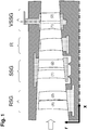
- the Fig. 1 shows in the meridional plane formed by the axial direction x and the radial direction r, a plurality of blade row groups, each of the blade row groups consisting of two similar and their relative arrangement to each other (both circumferentially and in the meridional direction) non-changing member blade rows. These are therefore double-row idlers or wheels.
- a rotor blade row group RSG consists of two rotor blade rows running at the same rotational speed and connected to one another; the first member of the group is marked with (1) and the second member of the group with (2).
- a stator blade row group SSG consists of two directly adjacent fixed stator blade rows (1) and (2).
- a variable stator vane group VSSG consists of two directly adjacent rows of stator blades (1) and (2), each with a blade of the front row are provided with a blade of the rear row on a common turntable and are thus adjustable together about the axis of rotation.
- All blade row groups according to the prior art have in common that no targeted shaping of the blade edges and no advantageous relationship of the individual blade edge shapes is provided.
- they are usually considered in the meridional plane (x-r) or axial plane (r-u), which does not allow conclusions about properties in the aerodynamically critical frame parallel or perpendicular to the chord of a blade section.
- two blade edges intersecting in the axial plane (x-r) can have no point of contact or intersection in a view parallel to the sinewave.
- Each of the blade row groups according to the invention also consists here of two identical and the relative position to each other not changing member blade rows.
- a rotor blade row group RSG consists of at least two rotor blade rows running at the same rotational speed and connected to one another.
- a stator blade row group SSG according to the invention consists of at least two directly adjacent stationary stator blade rows.
- a variable stator vane group VSSG according to the invention consists of at least two directly adjacent stator blade rows.
- a blade of one of the member blade rows may be provided with at least one blade of the member blade row immediately downstream thereof on a common turntable.
- at least two vanes belonging to different rows of vanes may each be arranged on an individual turntable.
- Each of the blade row groups RSG, SSG and VSSG according to the invention may also have more than two member blade rows.
- the described configuration of the blade row assembly includes the possibility that on at least one member blade row, the distance between two adjacent blades varies along the circumference. It may also be beneficial if the axial position of two adjacent blades of this blade row varies along the circumference. It may also be beneficial if the tread depth of two adjacent blades of this blade row varies along the circumference.
- the number of blades of two adjacent member blade rows are in a particular relationship, that is, the number of blades of the member blade row (i) is a multiple of the number of blades of the member blade row (i + 1), or the number The number of blades of the member blade row (i + 1) forms a multiple of the number of blades of the member blade row (i), or the number of blades of the member blade row (i) and the number of blades of the member blade row (i + 1) are the same. It may be particularly advantageous if the ratio of the number of blades of the rows (i) and (i + 1) is in the ratio of 1: 2.
- FIG Fig. 2 for defining meridional flow lines, a main flow path of a turbomachine with left-to-right flow (indicated by the thick arrow) in the meridional plane formed by the axial coordinate x and the radial coordinate r, the main flow path through the radially inner main flow path boundary HBi and the radially outer main flow path boundary HBo is limited. Centered between the radially inner main flow path boundary HBi and the radially outer main flow path boundary HBo is the mean meridional flow line SLM.
- VK and HK indicate the leading edge and the trailing edge of a vane arranged in the main flow path.
- a family of straight lines G (k) are given within the main flow path, whose members are each perpendicular to the mean meridional flow line SLM and terminate at the main flow path boundaries HB.
- Further meridional flow lines SL (j) are defined by the connection of points at equal percentage subdivision of the straight line G (k) between the main flow path boundary HB.
- the rotation of a meridional flow line around the machine axis results in a meridional flow area SF (j).
- the section of a meridional flow area with a blade of the turbomachine results in a meridional flow line section SLS (j).
- the quarter meridional flow line SLQ is obtained in each case.
- a profile-tendon-related coordinate system This shows the Fig. 3 initially on its left side by way of example an arrangement of two belonging to a blade row group according to the invention and adjacent member blade rows (i) and (i + 1) in the meridional plane formed by the axial direction x and the radial direction r.
- the arrangement according to the invention is shown in the region between the main flow path center (average meridional flow line SLM, along the meridional direction m there), and a main flow path boundary HB.
- the main flow path boundary HB represents a contour on the hub or on the housing of the turbomachine, for example on a turntable, a wall, a stator base, a stator cover strip, a rotor base or a rotor cover strip.
- the main flow path boundary HB is either fixedly connected to the end of at least one member blade row, or there is a gap between the Main flow path boundary and provided at least the end of a member blade row.
- the arrangement shows the two member blade rows (i) and (i + 1), each with two blade edges, leading edge VK (i) and trailing edge HK (i), respectively, leading edge VK (i + 1) and trailing edge HK (i + 1).
- the right side of the Fig. 3 shows the arrangement of the considered two member blade rows in a meridional flow area formed by the meridional coordinate m and the circumferential direction u.
- Corresponding circumferential development is illustrated by way of example for other meridional flow line sections on the mean meridional flow line blade section SLM in the main flow path center.
- the two rows of vanes have the same number of vanes.
- the suction sides of the blades (i) and (i + 1) are respectively marked SS (i) and SS (i + 1) and the printed pages are DS (i) and DS (i + 1).
- the blades may conveniently be provided so that between the pressure side of a blade (i) and the suction side of a blade (i + 1), a secondary passage (shown as a shaded area and marked with NP) is formed.
- a meridional engagement in at least one region of the main flow path height from the leading edge VK (i + 1) of the rear member blade row to the leading edge HK (i) of the forward member blade row is provided a meridional engagement the amount of which towards at least one of the main flow path boundaries HB in at least a subsection increases.
- meridional engagement may be provided in all embodiments of the invention.
- the Fig. 4 shows how the right side of the Fig. 3 , a meridional flow line blade cut.
- the definition of various relevant quantities and views in the plane given by the meridional direction m and the circumferential coordinate u is given.
- the main flow direction is through thick black arrows characterized.
- the connecting lines of the blade edges are respectively marked VK (i), HK (i), VK (i + 1) and HK (i + 1).
- Each blade profile is shown with its suction side SS, its pressure side DS. It should be noted that for purposes of clarity in the Fig. 4 and also in the other figures between the designation of the member blade rows (i) and (i + 1) and the designation of the individual blades of the member blade rows, ie the blades are also denoted by (i) and (i + 1).
- chord of the front blade Se (i) is defined as the pressure tangent to the profile of the blade (i).
- the chord of the rear blade Se (i + 1) is defined as the pressure tangent to the profile of the blade (i + 1).
- the stagger angle of the front blade lambda (i) ( ⁇ i) is defined as the inclination angle of the chord of the front blade S (i) against the meridional direction m.
- the stagger angle of the rear blade lambda (i + 1) ( ⁇ i + 1) is defined as the angle of inclination of the chord of the rear blade S (i + 1) against the meridional direction m.
- the coordinate direction s is inclined with lambdam against the meridional direction m and points downstream.
- the coordinate direction q is perpendicular to s and is oriented away from the pressure side of the blade (i).
- the coordinate direction or is perpendicular to s and q.
- the view B-B is tangent to the mean section meridional flow area (conical surface around the machine axis) and perpendicular to the mean chord direction of the blade arrangement in the meridional flow line blade section at SLQ marked by the coordinate direction s.
- the Fig. 5 shows as solid solid lines the edges of the front blade and as thick dotted lines the edges of the rear blade in the region between the main flow path boundary HB and the half-blade height defined average meridional flow line SLM, in the s-or-plane (view BB).
- the quarter meridional flow line SLQ is plotted with the origin of coordinates at the intersection of SLQ with the trailing edge of the front blade HK (i), which is the coordinate direction orthogonal to the meridional flow surface passing through SLQ.
- the coordinate direction s is parallel to SLQ.
- the coordinate direction or is orthogonal to SLQ and is not necessarily parallel to HK (i).
- the main flow direction is indicated by a thick arrow.
- auxiliary lines G1, G2, G3 and G4 important descriptive parameters for the blade edges of the member blade rows (i) and (i + 1) are defined.
- An auxiliary straight line runs through the intersections of a blade edge with the mean mer- dional current line SLM and the main flow path boundary HB: G1 for the edge VK (i), G2 for the edge HK (i), G3 for the edge VK (i + 1) and G4 for the edge HK (i + 1).
- the distance dor between SLM and HB is measured orthogonal to the quarter-meridional current line SLQ at the intersection with the trailing edge line HK (i) (in the direction of or and perpendicular to s), the auxiliary straight GH indicating the SLQ orthogonal direction.
- the tilt angle alpha1 of the leading edge line VK (i) is defined between the auxiliary straight G1 and the orthogonal of the quarter meridional flow line SLQ at the intersection with the auxiliary straight G1, and is considered as the blade row group having a left-to-right flow and the main flow path boundary HB pictorial lower limit, positively counted in the clockwise direction.
- the point of maximum edge curvature on the leading edge line VK (i) is indicated as P1.
- the tilt angle alpha2 of the trailing edge line HK (i) is defined between the auxiliary straight G2 and the orthogonal of the quarter meridional flow line SLQ at the intersection with the auxiliary straight G2, and is viewed as the blade row group with left-to-right flow and main flow path boundary HB as a pictorial bottom boundary. positively counted in the clockwise direction.
- the point of maximum edge curvature on the trailing edge line HK (i) is indicated as P2.
- the tilt angle alpha3 of the leading edge line VK (i + 1) is defined between the auxiliary straight G3 and the orthogonal of the quarter meridional flow line SLQ at the intersection with the auxiliary straight G3 and becomes imagewise lower when viewing the blade row group with left-to-right flow and main flow path boundary HB Limitation, positively counted in the clockwise direction.
- the point of maximum edge curvature on the leading edge line VK (i + 1) is indicated as P3.
- the tilt angle alpha4 of the trailing edge line HK (i) is defined between the auxiliary straight G4 and the orthogonal of the quarter meridional flow line SLQ at the intersection with the auxiliary straight G4 and becomes viewed as the blade row group with left-to-right flow and main flow path boundary HB as a pictorial bottom boundary. positively counted in the clockwise direction.
- the point of maximum edge curvature on the trailing edge line HK (i + 1) is indicated as P4.
- Edge type A a substantially linear course, characterized in that a very small degree of curvature of WG ⁇ 0.003 is provided.
- Edge type B a slightly curved course, characterized in that a small degree of warpage of 0.003 ⁇ WG ⁇ 0.01 is provided.
- Edge type C an at least partially curved course without change of curvature and with a degree of curvature of WG> 0.01, whereby a section with a curvature concave towards the blade pressure side is provided.
- Edge type D an at least partially curved course without change of curvature and with a degree of curvature of WG> 0.01, whereby a section with a convex curvature towards the blade pressure side is provided (mirror image qualitatively equal with type C).
- Edge type E an at least partially curved course with a curvature change and with a degree of curvature of WG> 0.01, wherein between the curvature change point and the Hauptströmungspfadberandung HB a section is provided with a concave to the blade pressure side curve.
- Edge type F an at least partially curved course with a curvature change and with a degree of curvature of WG> 0.01, wherein between the curvature change point and the Hauptströmungspfadberandung HB a section with a convex curvature to the blade pressure side is provided (mirror image qualitatively equal to type E).
- Edge type G an at least partially curved course with two changes of curvature and with a degree of curvature of WG> 0.01, whereby a section with a curvature concave towards the blade pressure side is provided between the two points of curvature change.
- Edge type H an at least partially curved course with two changes of curvature and with a degree of curvature of WG> 0.01, whereby a section with a convex curvature towards the blade pressure side is provided between the two points of curvature (mirror image qualitatively equal to type G).
- edges are either of the same type (also called equi-qualitative equality) or if two edges are of different types, but are mirror images of each other, eg types C and D, or types E and F, or types G and H (also referred to as opposing qualitative equality).
- FIG 11 shows a representation of the blade edges in view BB, which represents the ideal case for viewing the blade edges, but also determinations in deviating views of the blade row pairing with its four edges within an angular range of +/- 45 ° around the coordinate direction q may be relevant be, as long as it is orthogonal to the coordinate direction or. It is particularly useful if the edges of the blade row group are viewed in a view orthogonal to the coordinate directions s and or.
- blade row group if qualitative equality is provided for at least three of the four blade edges of the blade row pairing (i, i + 1). It may be advantageous if a same-quality equality is provided.
- blade row group if a qualitative equality is provided for all four blade edges of the blade row pairing (i, i + 1). It may be advantageous if a same-quality equality is provided.
- blade row group it may also be advantageous for the blade row group if a qualitative equality for the blade edges HK (i) and VK (i + 1) is provided. It may be advantageous if a same-quality equality is provided. Alternatively, it may be advantageous if an opposite qualitative equality is provided, i. The blade edges emerge mirror-inverted.
- blade row group if qualitative equality is provided for the blade edges HK (i) and HK (i + 1). It may be advantageous if a same-quality equality is provided.
- blade row group if a qualitative equality for the blade edges VK (i) and HK (i + 1) is provided. It may be advantageous if a same-quality equality is provided. Alternatively, it may be advantageous if an opposing qualitative equality is provided.
- one of the edge types A, B, C, E and H is provided on at least one of the edges VK (i) and VK (i + 1). It is advantageous if one of the edge types C, E and H is provided. It is additionally advantageous if an edge type C or alternatively an edge type E is provided. It is particularly advantageous if an edge type E is provided on both edges VK (i) and VK (i + 1).
- one of the edge types F and G is provided on at least one of the edges VK (i) and VK (i + 1). It is advantageous if an edge type F is provided. It is particularly advantageous if an edge type F is provided on both edges VK (i) and VK (i + 1).
- one of the edge types A, B, D, E and H is provided on at least one of the edges HK (i) and HK (i + 1). It is advantageous if one of the edge types B, D and E is provided. It is additionally advantageous if an edge type D or alternatively an edge type E is provided. It is particularly advantageous if an edge type E is provided on both edges HK (i) and HK (i + 1).
- one of the edge types C, F and G is provided on at least one of the edges HK (i) and HK (i + 1). It is advantageous if one of the edge types C and F is provided. It is additionally advantageous if an edge type C is provided. It is particularly advantageous if an edge type C is provided on both edges HK (i) and HK (i + 1).
- edge type C at the edge VK (i + 1) the edge type C and at the edge HK (i) one of the edge types A, B, C, D, E and F is provided. It is advantageous if an edge type D or E is provided on the edge HK (i).
- edge type E at the edge VK (i + 1) the edge type E and at the edge HK (i) one of the edge types A, B, C, D, E and F is provided. It is advantageous if an edge type C or F is provided on the edge HK (i).
- edge type F and at the edge HK (i) one of the edge types A, B, C, D, E and F is provided. It is advantageous if an edge type E or F is provided on the edge HK (i).
- the position of the change of curvature plays a role for the edge types with at least one change of curvature for the favorable influencing of the flow in the region near the main flow path boundary.
- the point of the curvature change of at least one of the vane edges VK (i), HK (i), VK (i + 1) and HK (i + 1) is in the region between the quarter meridional flow line SLQ and the main flow path boundary HB is provided. It is advantageous if the point of the curvature change is provided closer to the SLQ than to the HB.
- the point of curvature change for at least the leading edges VK (i) and VK (i + 1) or the trailing edges HK (i) and HK (i + 1) in the region between the quarter-meridional flow line SLQ and the Main flow path boundary HB is provided. It is advantageous if the point of the curvature change is provided closer to the SLQ than to the HB.
- the point of the curvature change of at least one of the blade edges VK (i), HK (i), VK (i + 1) and HK (i + 1) is closer to the HB than to the SLQ is provided. It is advantageous if this is true for at least one of the leading edges VK (i) and VK (i + 1).
- the point of curvature change is closer to the HB than to the leading edges VK (i) and VK (i + 1) or the trailing edges HK (i) and HK (i + 1) the SLQ is provided. It is advantageous if this applies to the leading edges VK (i) and VK (i + 1).
- the point of curvature change of at least one of the vane edges VK (i), HK (i), VK (i + 1), and HK (i + 1) is in the range between the quarter-meridional current line SLQ and the mean meridional flow line SLM is provided. It is advantageous if the point of curvature change is provided closer to the SLQ than to the SLM.
- the point of curvature change for at least the leading edges VK (i) and VK (i + 1) or the trailing edges HK (i) and HK (i + 1) in the range between the quarter-meridional current line SLQ and the mean meridional current line SLM is provided. It is advantageous if the point of curvature change is provided closer to the SLQ than to the SLM.
- the point of curvature change of all blade edges VK (i), HK (i), VK (i + 1) and HK (i + 1) in the area between the quarter meridional flow line SLQ and the mean meridional flow line SLM is provided. It is advantageous if the point of curvature change is provided closer to the SLQ than to the SLM.
- a blade half in the region between the mean meridional flow line SLM and the main flow path boundary HB It is favorable according to the invention if a tilt angle (alpha1, alpha3) of greater than zero is provided on at least one of the two leading edges VK (i) and VK (i + 1). It may be advantageous if both tilt angles (alpha1, alpha3) are greater than zero.
- both tilt angles are provided with values in the range of 0 ° ⁇ alpha ⁇ 20 °.
- a tilt angle (alpha1, alpha3) of less than zero is provided on at least one of the two leading edges VK (i) and VK (i + 1). It may be advantageous if both tilt angles (alpha1, alpha3) are less than zero. It may be particularly advantageous if both tilt angles are provided with values in the range of -5 ° ⁇ alpha ⁇ 0 °.
- a tilt angle (alpha2, alpha4) of less than zero is provided on at least one of the two trailing edges HK (i) and HK (i + 1). It may be advantageous if both tilt angles (alpha2, alpha4) are less than zero. It may be particularly advantageous if both tilt angles are provided with values in the range of -10 ° ⁇ alpha ⁇ 0 °.
- a tilt angle (alpha2, alpha4) of greater than zero is provided on at least one of the two trailing edges HK (i) and HK (i + 1). It may be advantageous if both tilt angles (alpha2, alpha4) are greater than zero. It may be particularly advantageous if both tilt angles are provided with values in the range of 0 ° ⁇ alpha ⁇ 10 °.
- a tilt angle of less than zero is provided on at least three of the four edges VK (i), HK (i), VK (i + 1) and HK (i + 1). It may be advantageous if the leading edge VK (i) has a tilt angle alpha1 of greater than zero. It may be particularly advantageous if the tilt angle alpha1 is provided with values in the range of 0 ° ⁇ alpha1 ⁇ 10 °.
- a tilt angle of greater than zero is provided on at least three of the four edges VK (i), HK (i), VK (i + 1) and HK (i + 1). It may be advantageous if the trailing edge HK (i + 1) has a tilt angle alpha4 of less than zero. It may be particularly advantageous if the tilt angle alpha4 is provided with values in the range of -5 ° ⁇ alpha4 ⁇ 0 °.
- both tilt angles alpha1 and alpha3 are provided with values in the range of 0 ° ⁇ alpha ⁇ 20 ° and both tilt angles alpha2 and alpha4 with values in the range of -10 ° ⁇ alpha ⁇ 0 °. It may be particularly advantageous if the tilt angle alpha1 and alpha 3 are equal within a tolerance of 2 °. It may also be beneficial if the tilt angle alpha2 and alpha 4 are equal within a tolerance of 2 °. In this case, it may additionally be favorable if the tilt angles alpha2 and alpha4 are small in terms of magnitude, according to -3 ° ⁇ alpha ⁇ 0 °. In this case, it may additionally be favorable if the tilt angles alpha1 and alpha3 are large, according to 10 ° ⁇ alpha ⁇ 20 °.
- both tilt angles alpha1 and alpha3 are provided with values in the range of -10 ° ⁇ alpha ⁇ 0 ° and both tilt angles alpha2 and alpha4 with values in the range of 0 ° ⁇ alpha ⁇ 20 °. It may be particularly advantageous if the tilt angle alpha1 and alpha 3 are equal within a tolerance of 2 °. It may also be beneficial if the tilt angle alpha2 and alpha 4 are equal within a tolerance of 2 °. In this case, it may additionally be favorable if the tilt angles alpha1 and alpha3 are small in terms of magnitude, according to -3 ° ⁇ alpha ⁇ 0 °. In this case, it may additionally be favorable if the tilt angles alpha2 and alpha4 are large, according to 10 ° ⁇ alpha ⁇ 20 °.
- a tilt angle (alpha2, alpha4) of greater than zero is provided on at least one of the two trailing edges HK (i) and HK (i + 1), where alpha4 is greater than alpha2. It may be particularly advantageous if a larger tilt angle is provided at the HK (i + 1) than at the VK (i), corresponding to alpha4> alpha1. It may additionally be advantageous if at the VK (i + 1) a larger tilt angle is provided as at the VK (i), corresponding to alpha3> alpha1. It may additionally be advantageous if a tilt angle greater than zero is provided at the VK (i).
- the tilt angles are provided at the same size on at least two of the four blade edges VK (i), HK (i), VK (i + 1) and HK (i + 1) within a tolerance of 2 °. It may be advantageous if at least three of the four blade edges VK (i), HK (i), VK (i + 1) and HK (i + 1) within a tolerance of 2 °, the tilt angle are the same size. It may be particularly advantageous if at all four blade edges VK (i), HK (i), VK (i + 1) and HK (i + 1) within a tolerance of 2 °, the tilt angle are the same size.
- tilting angles ⁇ 1 and ⁇ 2 are provided equal to the blade edges VK (i) and HK (i) within a tolerance of 2 °. It is furthermore advantageous if the tilting angles ⁇ 1 and ⁇ 2 are provided with the same amounts but opposite sign at the blade edges VK (i) and HK (i) within a tolerance of 2 °.
- tilt angles alpha3 and alpha4 are provided at the blade edges VK (i + 1) and HK (i + 1) within a tolerance of 2 °. It is also advantageous if the tilting angles ⁇ 3 and ⁇ 4 are provided with the same amounts but opposite sign at the blade edges VK (i + 1) and HK (i + 1) within a tolerance of 2 °.
- tilt angles ⁇ 2 and ⁇ 3 are provided at the blade edges HK (i) and VK (i + 1) within a tolerance of 2 °. It is also favorable if the tilt angles ⁇ 2 and ⁇ 3 are provided with the same amounts but opposite sign at the blade edges HK (i) and VK (i + 1) within a tolerance of 2 °.
- tilting angles alpha1 and alpha4 are provided at the same size on both edges VK (i) and HK (i + 1) within a tolerance of 2 °. It is furthermore advantageous if the tilting angles ⁇ 1 and ⁇ 4 are provided with the same amounts but opposite sign at the blade edges VK (i) and HK (i + 1) within a tolerance of 2 °.
- leading edge VK (i) is provided with a positive tilt angle alpha1> 0 and the trailing edge HK (i + 1) with a negative tilt angle alpha4 ⁇ 0.
- the front edge VK (i) is provided with a negative tilt angle alpha1 ⁇ 0 and the rear edge HK (i + 1) with a positive tilt angle alpha4> 0.
- trailing edge HK (i) is provided with a negative tilt angle alpha2 ⁇ 0 and the leading edge VK (i + 1) with a positive tilt angle alpha3> 0.
- trailing edge HK (i) is provided with a positive tilt angle alpha2> 0 and the leading edge VK (i + 1) with a negative tilt angle alpha3 ⁇ 0.
- the two edges HK (i) and VK (i + 1) are provided with larger tilt angles than the two edges VK (i) and HK (i + 1). It may be advantageous if the tilt angles alpha1 and alpha4 of the edges VK (i) and HK (i + 1) are small in magnitude, according to -3 ° ⁇ alpha ⁇ 3 °. It may additionally be advantageous if the tilt angle alpha1 is positive and the tilt angle alpha4 is negative.
- the two edges HK (i) and VK (i + 1) are provided with smaller tilt angles than the two edges VK (i) and HK (i + 1). It may be advantageous if the tilt angles alpha1 and alpha4 of the edges VK (i) and HK (i + 1) are small in magnitude, according to -3 ° ⁇ alpha ⁇ 3 °. It may additionally be advantageous if the tilt angle alpha1 is positive and the tilt angle alpha4 is negative.
- the tilt angles alpha1, alpha2 and alpha4 of the edges VK (i), HK (i) and HK (i + 1) are small in absolute value, according to -3 ° ⁇ alpha ⁇ 3 °. It may additionally be advantageous if the tilt angle alpha1 is positive, the tilt angle alpha4 is negative. It may additionally be advantageous if the tilt angle alpha3 is negative. It may additionally be advantageous if the tilt angle alpha3 of the leading edge VK (i + 1) is provided positively with values in the range of 5 ° ⁇ alpha ⁇ 20 °. For all embodiments of the blade row group according to the invention, it may be advantageous if the VK (i) has a larger tilt angle than all other blade edges.
- a curvature degree of one of the classes 2, 3 and 4 is provided on the front edge VK (i). It is advantageous if at the VK (i) a degree of curvature of one of the classes 3 and 4 is provided. It is additionally advantageous if a degree of curvature of class 4 is provided on the VK (i).
- a curvature degree of one of the classes 1, 2, 3 and 4 is provided at the front edge VK (i + 1). It is advantageous if a degree of curvature of one of the classes 2, 3 and 4 is provided at the VK (i + 1). It is additionally advantageous if a degree of curvature of one of the classes 3 and 4 is provided at the VK (i + 1). It is particularly advantageous if a degree of curvature of class 4 is provided at the VK (i + 1).
- HK (i) a degree of curvature of one of the classes 1, 2, and 3 is provided. It is advantageous if at the HK (i) a degree of curvature of one of the classes 1 and 2 is provided. It is additionally advantageous if a curvature degree of class 2 is provided at the HK (i).
- a curvature degree of one of the classes 1, 2 and 3 is provided at the trailing edge HK (i + 1). It is advantageous if a degree of curvature of one of the classes 1 and 2 is provided at the HK (i + 1). It is additionally advantageous if a degree of curvature of class 2 is provided at the HK (i + 1).
- a curvature degree of one of the classes 3 and 4 is provided at the front edge VK (i) and a curvature degree of one of the classes 1 and 2 is provided at the rear edge HK (i + 1). It is advantageous if a curvature degree of class 3 is provided on the VK (i) and a degree of curvature of class 2 is provided on the HK (i + 1). It is additionally advantageous if a degree of curvature of class 3 is provided at the edges HK (i) and VK (i + 1).
- a curvature degree of one of the classes 1 and 2 is provided on the front edge VK (i) and on the rear edge HK (i + 1). It is advantageous if a degree of curvature of class 2 is provided at the VK (i) and at the HK (i + 1). It is additionally advantageous if a degree of curvature of class 1 is provided at the edges HK (i) and VK (i + 1).
- a curvature degree of one of the classes 3 and 4 is provided at the front edge VK (i) and at the rear edge HK (i + 1). It is advantageous if a curvature degree of class 4 is provided on the VK (i) and a degree of curvature of class 3 is provided on the HK (i + 1). It is additionally advantageous if a degree of curvature of class 3 is provided at the edges HK (i) and VK (i + 1).
- a curvature degree of one of the classes 1 and 2 is provided on the front edge VK (i) and a degree of curvature of one of the classes 3 and 4 is provided on the trailing edge HK (i + 1). It is advantageous if a curvature degree of class 2 is provided on the VK (i) and a degree of curvature of class 3 is provided on the HK (i + 1). It is additionally advantageous if a degree of curvature of class 3 is provided at the edges HK (i) and VK (i + 1).
- VK (i), HK (i), VK (i + 1) and HK (i + 1) vaulting degrees of the same class are provided on all edges. It may be advantageous if the degree of curvature is provided at all edges within a tolerance of 0.02 the same size.
- the position of the maximum curvature (d1, d2, d3, d4) also plays a role in favoring the flow in the region near the main flow path boundary.
- the point of maximum curvature of at least one of the vane edges VK (i), HK (i), VK (i + 1) and HK (i + 1) lies in the region between the quarter meridional flow line SLQ and the main flow path boundary HB is provided. It is advantageous if the point of maximum curvature is provided closer to the SLQ than to the HB.
- the point of maximum curvature for at least the leading edges VK (i) and VK (i + 1) or the trailing edges HK (i) and HK (i + 1) in the region between the quarter-meridional flow line SLQ and the Main flow path boundary HB is provided. It is advantageous if the point of maximum curvature is provided closer to the SLQ than to the HB.
- the point of maximum curvature of at least one of the blade edges VK (i), HK (i), VK (i + 1) and HK (i + 1) is closer to the HB than to the SLQ is provided. It is advantageous if this is true for at least one of the leading edges VK (i) and VK (i + 1).
- the point of maximum curvature for at least the leading edges VK (i) and VK (i + 1) or the trailing edges HK (i) and HK (i + 1) is closer to the HB than to the SLQ is provided. It is advantageous if this applies to the leading edges VK (i) and VK (i + 1).
- the point of maximum curvature of at least one of the vane edges VK (i), HK (i), VK (i + 1), and HK (i + 1) is in the range between the quarter-meridional streamline SLQ and the mean meridional flow line SLM is provided. It is advantageous if the point of maximum curvature is provided closer to the SLQ than to the SLM.
- the point of maximum curvature for at least the leading edges VK (i) and VK (i + 1) or the trailing edges HK (i) and HK (i + 1) in the range between the quarter-meridional current line SLQ and the mean meridional current line SLM is provided. It is advantageous if the point of maximum curvature is provided closer to the SLQ than to the SLM.
- the point of maximum curvature of all vane edges VK (i), HK (i), VK (i + 1) and HK (i + 1) is in the range between the quarter-meridional current line SLQ and the mean meridional flow line SLM is provided. It is advantageous if the point of maximum curvature is provided closer to the quarter meridional streamline SLQ than to the mean meridional streamline SLM.
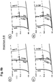
- FIGS. 6a to 6e In the partial images P1 to P20, the four blade edges VK (i), HK (i), VK (i + 1) and HK (i + 1) of two adjacent and successively arranged blades i and i + 1 two rows of blades of a blade row group according to the invention in the view BB according to the Fig. 4 in the region between the mean meridional flow line SLM and the main flow path boundary HB. Halfway between the mean meridional flow line SLM and the main flow path boundary HB, the quarter meridional flow line SLQ is drawn in each case.
- the partial illustration P1 shows the variant according to the invention of a blade row group with the following features: at the VK (i) is an edge type E, at the HK (i) an edge type D, at the VK (i + 1) an edge type D, and at the HK (i + 1) an edge type E provided.
- the edges HK (i) and VK (i + 1) and VK (i) and HK (i + 1) are each of the same edge type. It may be advantageous if the edge VK (i) has the point of curvature change, as shown, in the area between SLQ and HB; in a particular case, the point of curvature change may be provided on the SLQ.
- the edge HK (i) is located entirely upstream of the edge VK (i + 1); alternatively, unlike the illustrated, the edge HK (i) may be located entirely downstream of the edge VK (i + 1). It is in any case advantageous if the edges HK (i) and VK (i + 1) are substantially parallel (within a tolerance of 2 ° local tilt angle). It may additionally be advantageous if the edges VK (i) and HK (i + 1) in the region between SLQ and HB steadily move away from one another in the direction of HB. It may additionally be advantageous if all four blade edges at the SLM substantially perpendicularly (within a tolerance of 2 °) enclose a right angle with the SLM. It may additionally be advantageous if the trailing edge HK (i + 1) encloses a right angle at the HB with the HB substantially (within a tolerance of 2 °).
- the local inclination angle of a blade edge on the SLM or on the HB is always measured clockwise from the respective edge on the shortest path to the SLM or HB (see partial illustration P1).
- Subpicture P2 shows the variant according to the invention of a blade row group with the following features: at the VK (i) is an edge type B, at the HK (i) an edge type F, at the VK (i + 1) an edge type F, and at the HK (i + 1) an edge type B is provided.
- the edges HK (i) and VK (i + 1) and VK (i) and HK (i + 1) are each of the same edge type. It may be advantageous if the edges HK (i) and VK (i + 1) have the point of curvature change, as shown, in the range between SLQ and HB; in a particular case, the point of curvature change may be provided on the SLQ.
- the edge HK (i) is located entirely upstream of the edge VK (i + 1); alternatively, unlike the illustrated, the edge HK (i) may be located entirely downstream of the edge VK (i + 1). It is in any case advantageous if the edges HK (i) and VK (i + 1) are substantially parallel (within a tolerance of 2 ° local tilt angle). It may additionally be advantageous if the edges VK (i) and HK (i + 1) are substantially parallel (within a tolerance of 2 ° local tilt angle).
- all four blade edges at the SLM substantially perpendicularly (within a tolerance of 2 °) enclose a right angle with the SLM. It may additionally be advantageous if the trailing edge HK (i + 1) encloses a right angle at the HB with the HB substantially (within a tolerance of 2 °). It may additionally be advantageous if all four blade edges at the SLM substantially perpendicularly (within a tolerance of 2 °) enclose a right angle with the SLM. It may additionally be advantageous if all four blade edges include a right angle locally (substantially within a tolerance of 2 °) at the HB with the HB substantially.
- the subpicture P3 shows the variant according to the invention of a blade row group with the following features: at the VK (i) is an edge type A, at the HK (i) an edge type F, at the VK (i + 1) an edge type F, and at the HK (i + 1) an edge type A provided.
- the edges HK (i) and VK (i + 1) and VK (i) and HK (i + 1) are each of the same edge type. It may be advantageous if the edges HK (i) and VK (i + 1) have the point of curvature change, as shown, in the range between SLQ and HB; in a particular case, the point of curvature change may be provided on the SLQ.
- the edge HK (i) is located entirely downstream of the edge VK (i + 1); alternatively, unlike the illustrated, the edge HK (i) may be located entirely upstream of the edge VK (i + 1). It is in any case advantageous if the edges HK (i) and VK (i + 1) are substantially parallel (within a tolerance of 2 ° local tilt angle).
- edges VK (i) and HK (i + 1) are substantially parallel (within a tolerance of 2 ° local tilt angle). It may additionally be advantageous if all four blade edges at the SLM substantially perpendicularly (within a tolerance of 2 °) enclose a right angle with the SLM. It may additionally be advantageous if the trailing edge HK (i + 1) encloses a right angle at the HB with the HB substantially (within a tolerance of 2 °). It may additionally be beneficial if all four Shallow edges at the HB with the HB essentially at a right angle (within a tolerance of 2 °).
- the subpicture P4 shows the variant according to the invention of a blade row group with the following features: at the VK (i) is an edge type F, at the HK (i) an edge type F, at the VK (i + 1) an edge type F, and at the HK (i + 1) an edge type A provided.
- the edges VK (i), HK (i) and VK (i + 1) are of the same edge type. It may be advantageous if the edges VK (i), HK (i) and VK (i + 1) have the point of curvature change, as shown, in the range between SLQ and HB; in a particular case, the point of curvature change may be provided on the SLQ.
- the edge HK (i) intersects the edge VK (i + 1) and is located in a region adjacent to the HB downstream of the VK (i + 1). It may be advantageous if the point of intersection of the edges HK (i) and VK (i + 1) is provided in the region between the SLQ and the HB; Alternatively, it may be advantageous in the case of structural restrictions if the point of intersection (other than shown) is provided in the area between the SLM and the SLQ or even on the SLQ.
- edges VK (i) and HK (i) are substantially parallel (within a tolerance of 2 ° local tilt angle). It may additionally be advantageous if all four blade edges at the SLM substantially perpendicularly (within a tolerance of 2 °) enclose a right angle with the SLM. It may additionally be advantageous if the trailing edge HK (i + 1) encloses a right angle at the HB with the HB substantially (within a tolerance of 2 °). It may additionally be advantageous if all four blade edges include a right angle locally (substantially within a tolerance of 2 °) at the HB with the HB substantially.
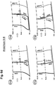
- Partial picture P5 of the Fig. 6b shows the variant according to the invention of a blade row group with the following features: at the VK (i) is an edge type C, at the HK (i) an edge type C, at the VK (i + 1) an edge type C, and at the HK (i + 1) an edge type B is provided.
- the edges VK (i), HK (i) and VK (i + 1) are of the same edge type. It may be advantageous if the edges VK (i), HK (i) and VK (i + 1) have the point of maximum curvature in the range between SLQ and HB; in a particular case, the point of maximum buckling may be provided on the SLQ.
- the edge HK (i) is at least partially (or as shown here entirely) upstream of the edge VK (i + 1); alternatively, unlike the illustrated, the edge HK (i) may be located entirely downstream of the edge VK (i + 1). It is in any case advantageous if the edges HK (i) and VK (i + 1) are essentially parallel (within a tolerance of 2 ° local tilt angle). It may additionally be advantageous if the edges VK (i) and HK (i + 1) in the region between SLQ and HB steadily move away from one another in the direction of HB. It may additionally be advantageous if all four blade edges at the SLM substantially perpendicularly (within a tolerance of 2 °) enclose a right angle with the SLM. It may additionally be advantageous if the trailing edge HK (i + 1) encloses a right angle at the HB with the HB substantially (within a tolerance of 2 °).
- the edge HK (i) is provided upstream of the edge VK (i + 1) and these two edges form an intersection. It is advantageous if the point of intersection is provided in the area between the SLQ and the HB, ideally closer to the SLQ.
- the subpicture P6 shows the variant according to the invention of a blade row group with the following features: at the VK (i) is an edge type C, at the HK (i) an edge type C, at the VK (i + 1) an edge type C, and at the HK (i + 1) an edge type C provided.
- the edges VK (i), HK (i), VK (i + 1) and HK (i + 1) are of the same edge type. It may be advantageous if all edges have the point of maximum curvature in the range between SLQ and HB; in a particular case, the point of maximum buckling may be provided on the SLQ.
- the edge HK (i) is at least partially (or as shown here entirely) downstream of the edge VK (i + 1); alternatively, unlike the illustrated, the edge HK (i) may be located entirely upstream of the edge VK (i + 1). It is in any case advantageous if the edges HK (i) and VK (i + 1) are substantially parallel (within a tolerance of 2 ° local tilt angle). It may additionally be advantageous if the edges VK (i) and HK (i + 1) are substantially parallel (within a tolerance of 2 ° local tilt angle).
- all four blade edges at the SLM substantially perpendicularly (within a tolerance of 2 °) enclose a right angle with the SLM. It may additionally be advantageous if an acute angle of less than 75 ° is provided at all four blade edges locally at the HB between the HB and the respective edge. It may additionally be advantageous if, in a region adjacent to the SLM, the edge HK (i) is provided upstream of the edge VK (i + 1) and these two edges form an intersection. It is advantageous if the point of intersection is provided in the area between the SLQ and the HB, ideally closer to the SLQ.
- the partial image P7 shows the variant according to the invention of a blade row group with the following features: at the VK (i) an edge type C is provided, at the HK (i) an edge type C and at the VK (i + 1) an edge type C.
- the edges VK (i), HK (i) and VK (i + 1) are of the same edge type. It may be advantageous if these edges have the point of maximum curvature in the range between SLQ and HB; in a particular case, the point of maximum buckling may be provided on the SLQ.
- the edge HK (i) is at least partially (or as shown here entirely) downstream of the edge VK (i + 1).
- edges HK (i) and VK (i + 1) move away from each other in the area between the SLQ and the HB in the direction of the HB and if the VK (i + 1) locally at the HB with the HB includes a sharper angle than the HK (i).
- an edge type C is likewise provided at the HK (i + 1). It may additionally be advantageous if the edges HK (i) and HK (i + 1) approach each other in the region between the SLQ and the HB in the direction of the HB. It may additionally be advantageous if the edges VK (i) and HK (i + 1) approach each other in the area between the SLQ and the HB in the direction of the HB. It may additionally be advantageous if all four blade edges at the SLM substantially perpendicularly (within a tolerance of 2 °) enclose a right angle with the SLM.
- an acute angle of less than 75 ° is provided at all four blade edges locally at the HB between the HB and the respective edge. It may additionally be advantageous if, in a region adjacent to the SLM, the edge HK (i) is provided upstream of the edge VK (i + 1) and these two edges form an intersection. It is advantageous if the point of intersection is provided in the area between the SLQ and the HB, ideally closer to the SLQ.
- the partial image P8 shows the variant according to the invention of a blade row group with the following features: at the VK (i) an edge type E is provided, at the HK (i) an edge type E and at the VK (i + 1) an edge type C.
- the edges VK (i) and HK (i) are of the same edge type. It may be advantageous if these edges have the point of curvature change in the range between SLQ and HB; in a particular case, the point of curvature change may be provided on the SLQ.
- the edge HK (i) is at least partially located downstream of the edge VK (i + 1).
- edges HK (i) and VK (i + 1) move away from each other in a region adjacent to the HB in the direction of HB and if the VK (i + 1) locally at the HB with HB Angle includes as the HK (i).
- an edge type C is likewise provided at the HK (i + 1). It may additionally be advantageous if the edges HK (i) and HK (i + 1) approach each other in the area between the SLQ and the HB in the direction of the HB and if the HK (i + 1) is local to the HB HB includes a sharper angle than HK (i). It may additionally be advantageous if the edges VK (i) and HK (i + 1) approach each other in the area between the SLQ and the HB in the direction of the HB. It may additionally be advantageous if all four blade edges at the SLM substantially perpendicularly (within a tolerance of 2 °) enclose a right angle with the SLM.
- an acute angle of less than 75 ° is provided at all four blade edges locally at the HB between the HB and the respective edge. It may additionally be advantageous if, in a region adjacent to the SLM, the edge HK (i) is provided upstream of the edge VK (i + 1) and these two edges form an intersection. It is advantageous if the point of intersection is provided in the area between the SLQ and the HB, ideally closer to the SLQ.
- the partial picture P9 of the Fig. 6c shows the variant according to the invention of a blade row group with the following features: at the VK (i) is an edge type B, at the HK (i) an edge type B, at the VK (i + 1) an edge type C and at the HK (i + 1 ) an edge type B is provided.
- the edges VK (i), HK (i) and HK (i + 1) are of the same edge type. It may be advantageous if the edge VK (i + 1) has the point of maximum curvature in the range between SLQ and HB; in a particular case, the point of maximum buckling may be provided on the SLQ.
- the edge HK (i) is at least partially located downstream of the edge VK (i + 1).
- edges HK (i) and VK (i + 1) move away from each other in a region adjacent to the HB in the direction of the HB and if the edge VK (i + 1) locally at the HB with the HB includes a sharper angle than the HK (i). It may additionally be advantageous if the edges VK (i) and VK (i + 1) approach each other in the area between the SLQ and the HB in the direction of the HB and if the edge VK (i + 1) is local to the HB with HB at a sharper angle than VK (i).
- edges VK (i) and HK (i) approach each other in a region adjacent to HB in the direction of HB. It may additionally be advantageous if all four blade edges at the SLM substantially perpendicularly (within a tolerance of 2 °) enclose a right angle with the SLM. It may additionally be advantageous if an acute angle of less than 75 ° is provided locally at the HB only between the edge VK (i + 1) and the HB. It may additionally be advantageous if, in a region adjacent to the SLM, the edge HK (i) is provided upstream of the edge VK (i + 1) and these two edges form an intersection. It is advantageous if the point of intersection is provided in the area between the SLQ and the HB, ideally closer to the SLQ.
- the subpicture P10 shows the inventive variant of a blade row group with the following features: the front and the rear blade have mirror image same edge types, in such a way that at the VK (i) an edge type B, at the HK (i) an edge type D, at the VK (i + 1) an edge type C and at the HK (i + 1) an edge type B is provided.
- the edges VK (i) and HK (i + 1) are of the same edge type. It may be advantageous if the edges HK (i) and VK (i + 1) have the point of maximum curvature in the range between SLQ and HB; in a particular case, the point of maximum buckling may be provided on the SLQ.
- the edge HK (i) is at least partially located downstream of the edge VK (i + 1).
- edges HK (i) and VK (i + 1) move away from each other in a region adjacent to the HB in the direction of the HB and if the edge VK (i + 1) locally at the HB with the HB more acute angle and the HK (i) includes an obtuse angle. It may additionally be advantageous if the edges VK (i) and VK (i + 1) approach each other in the area between the SLQ and the HB in the direction of the HB and if the edge VK (i + 1) is local to the HB with HB at a sharper angle than VK (i).
- edges HK (i) and HK (i + 1) approach each other in a region adjacent to the HB in the direction of HB, and if the edge HK (i) locally adjoins the HB with the HB includes a duller angle than the HK (i + 1). It may additionally be advantageous if all four blade edges at the SLM substantially perpendicularly (within a tolerance of 2 °) enclose a right angle with the SLM.
- an acute angle of less than 75 ° is provided locally at the HB between the edge VK (i + 1) and the HB and an obtuse angle greater than 105 ° is provided between the edge HK (i) and the HB . It may additionally be advantageous if, in a region adjacent to the SLM, the edge HK (i) is provided upstream of the edge VK (i + 1) and these two edges form an intersection. It is advantageous if the point of intersection is provided in the area between the SLQ and the HB, ideally closer to the SLQ.
- the subpicture P11 shows the variant according to the invention of a blade row group with the following features: the front and the rear blade have mirror-image equal edge types, in such a way that at the VK (i) an edge type C, at the HK (i) an edge type E, at the VK (i + 1) an edge type F and at the HK (i + 1) an edge type D is provided.
- the edges VK (i) and HK (i + 1) are of mirror-image-like edge type. It may be advantageous if the edges VK (i) and HK (i + 1) have the point of maximum curvature in the range between SLQ and HB; in a particular case, the point of maximum buckling may be provided on the SLQ.
- edges HK (i) and VK (i + 1) are of mirror-image-like edge type. It may be advantageous if the edges VK (i) and HK (i + 1) have the point of curvature change in the range between SLQ and HB; in a particular case, the point of curvature change may be provided on the SLQ.
- the edge HK (i) is at least partially located downstream of the edge VK (i + 1).
- edges HK (i) and VK (i + 1) move away from each other in a region adjacent to HB in the direction of HB. It may additionally be advantageous if the edges VK (i) and VK (i + 1) approach each other in the region between the SLQ and the HB in the direction of the HB. It may additionally be advantageous if the edges HK (i) and HK (i + 1) approach each other in a region adjacent to HB in the direction of HB. It may additionally be advantageous if all four blade edges at the SLM substantially perpendicularly (within a tolerance of 2 °) enclose a right angle with the SLM.
- an acute angle is provided locally at the HB between the edge VK (i + 1) and the HB and an obtuse angle is provided between the edge HK (i) and the HB. It may additionally be advantageous if, in a region adjacent to the SLM, the edge HK (i) is provided upstream of the edge VK (i + 1) and these two edges form an intersection. It is advantageous if the point of intersection is provided in the area between the SLQ and the HB, ideally closer to the SLQ.
- the subpicture P12 shows the variant according to the invention of a row of vane rows with the following features: the front and rear vane have mirror-inverted edge types, in such a way that at the VK (i) an edge type C, at the HK (i) an edge type D, at the VK (i + 1) an edge type C and at the HK (i + 1) an edge type D is provided.
- the edges VK (i) and HK (i + 1) are of mirror-image-like edge type.
- the edges HK (i) and VK (i + 1) are of mirror-image-like edge type.
- edges may have the point of maximum curvature in the range between SLQ and HB; in a special case, the point maximum curvature on the SLQ be provided.
- the edge HK (i) is at least partially located downstream of the edge VK (i + 1) (or even as shown here, entirely downstream of VK (i + 1)).
- edges HK (i) and VK (i + 1) move away from each other in a region adjacent to HB in the direction of HB. It may additionally be advantageous if the edges VK (i) and VK (i + 1) approach each other in the region between the SLQ and the HB in the direction of the HB. It may additionally be advantageous if the edges HK (i) and HK (i + 1) approach each other in a region adjacent to HB in the direction of HB. It may additionally be advantageous if all four blade edges at the SLM substantially perpendicularly (within a tolerance of 2 °) enclose a right angle with the SLM.
- an acute angle is provided locally at the HB between the edge VK (i + 1) and the HB and an obtuse angle is provided between the edge HK (i) and the HB. It may additionally be advantageous if, in a region adjacent to the SLM, the edge HK (i) is provided upstream of the edge VK (i + 1) and these two edges form an intersection. It is advantageous if the point of intersection is provided in the area between the SLQ and the HB, ideally closer to the SLQ.
- Partial picture P13 of the Fig. 6d shows the inventive variant of a blade row group with the following features: the front and the rear blade have the same edge types, here such that at the VK (i) an edge type C, at the HK (i) an edge type B, at the VK (i + 1) an edge type C and at the HK (i + 1) an edge type B is provided.
- the edges VK (i) and VK (i + 1) are of the same edge type. It may be advantageous if the edges VK (i) and VK (i + 1) have the point of maximum curvature in the range between SLQ and HB; in a particular case, the point of maximum buckling may be provided on the SLQ.
- the edges HK (i) and HK (i + 1) are of the same edge type.
- the edge HK (i) is located at least partially downstream of the edge VK (i + 1) (or even entirely downstream of the VK (i + 1) as not shown here).
- edges VK (i) and VK (i + 1) are substantially parallel (within a tolerance of 2 ° local tilt angle). It may additionally be advantageous if the edges HK (i) and HK (i + 1) are substantially parallel (within a tolerance of 2 ° local tilt angle). It may additionally be advantageous if all four blade edges at the SLM substantially perpendicularly (within a tolerance of 2 °) enclose a right angle with the SLM. It may additionally be advantageous if locally at the HB between the edge VK (i) and the HB an acute angle of less than 75 ° and between the edge VK (i + 1) and the HB an acute angle of less than 75 ° is provided.
- the edge HK (i) is provided upstream of the edge VK (i + 1) and these two edges form an intersection. It is advantageous if the point of intersection is provided in the area between the SLQ and the HB, ideally closer to the SLQ.
- the subpicture P14 shows the variant according to the invention of a blade row group with the following features: the front and the rear blade have the same edge types, here such that at the VK (i) an edge type F, at the HK (i) an edge type C, at the VK (i + 1) an edge type F and at the HK (i + 1) an edge type C is provided.
- the edges VK (i) and VK (i + 1) are of the same edge type. It may be advantageous if the edges VK (i) and VK (i + 1) have the point of curvature change in the range between SLQ and HB; in a particular case, the point of curvature change may be provided on the SLQ.
- the edges HK (i) and HK (i + 1) are of the same edge type.
- edges HK (i) and HK (i + 1) have the point of maximum curvature in the range between SLQ and HB; in a particular case, the point of maximum buckling may be provided on the SLQ.
- the edge HK (i) is at least partially located downstream of the edge VK (i + 1) (or as shown here, entirely downstream of the VK (i + 1)). It may be advantageous if the edges HK (i) and VK (i + 1) in a region adjoining the HB move away from each other in the direction of the HB. It may be advantageous if the edges VK (i) and VK (i + 1) are substantially parallel (within a tolerance of 2 ° local tilt angle).
- edges HK (i) and HK (i + 1) are substantially parallel (within a tolerance of 2 ° local tilt angle). It may additionally be advantageous if all four blade edges at the SLM substantially perpendicularly (within a tolerance of 2 °) enclose a right angle with the SLM.
- an acute angle of less than 75 ° is provided locally at the HB between the edge HK (i) and the HB and an acute angle of less than 75 ° is provided between the edge HK (i + 1) . It may additionally be advantageous if, in a region adjacent to the SLM, the edge HK (i) is provided upstream of the edge VK (i + 1) and these two edges form an intersection. It is advantageous if the point of intersection is provided in the area between the SLQ and the HB, ideally closer to the SLQ.
- the subpicture P15 shows the variant according to the invention of a blade row group with the following features: the front and the rear blade have identical edge types, here such that at the VK (i) an edge type F, at the HK (i) an edge type E, at the VK (i + 1) an edge type F and at the HK (i + 1) an edge type E is provided.
- the edges VK (i) and VK (i + 1) are of the same edge type. It may be advantageous if the edges VK (i) and VK (i + 1) have the point of curvature change in the range between SLQ and HB; in a particular case, the point of curvature change may be provided on the SLQ.
- the edges HK (i) and HK (i + 1) are of the same edge type.
- edges HK (i) and HK (i + 1) have the point of curvature change in the range between SLQ and HB; in a particular case, the point of curvature change may be provided on the SLQ.
- the edge HK (i) is located at least partially upstream of the edge VK (i + 1) (or as shown here, entirely upstream of the VK (i + 1)). It may be advantageous if the edges VK (i) and VK (i + 1) are substantially parallel (within a tolerance of 2 ° local tilt angle). It may additionally be advantageous if the edges HK (i) and HK (i + 1) are substantially parallel (within a tolerance of 2 ° local tilt angle). It may additionally be advantageous if all four blade edges at the SLM substantially perpendicularly (within a tolerance of 2 °) enclose a right angle with the SLM.
- an acute angle of less than 75 ° is provided locally at the HB between the edge VK (i) and HB and an acute angle of less than 75 ° is provided between the edge VK (i + 1) and HB ,
- the edge HK (i) is provided downstream of the edge VK (i + 1).
- the edges HK (i) and VK (i + 1) form an intersection. It is advantageous if the point of intersection is provided in the area between the SLQ and the HB, ideally closer to the SLQ.
- the subpicture P16 shows the variant according to the invention of a blade row group with the following features: the front and the rear blade have the same edge types, here such that at the VK (i) an edge type E, at the HK (i) an edge type E, at the VK (i + 1) an edge type E and at the HK (i + 1) an edge type E is provided.
- the edges VK (i), HK (i), VK (i + 1) and HK (i + 1) are of the same edge type. It may be advantageous if the edges of the point of curvature change in the area between SLQ and HB; in a particular case, the point of curvature change may be provided on the SLQ.
- the edge HK (i) is at least partially located downstream of the edge VK (i + 1) (or as shown here, entirely downstream of the VK (i + 1)).
- edges HK (i) and VK (i + 1) move away from each other in a region adjacent to HB in the direction of HB. It may be advantageous if the edges VK (i) and VK (i + 1) are substantially parallel (within a tolerance of 2 ° local tilt angle). It may additionally be advantageous if the edges HK (i) and HK (i + 1) are substantially parallel (within a tolerance of 2 ° local tilt angle). It may additionally be advantageous if all four blade edges at the SLM substantially perpendicularly (within a tolerance of 2 °) enclose a right angle with the SLM.
- an acute angle of less than 75 ° is provided locally at the HB between the edge VK (i) and HB and an acute angle of less than 75 ° is provided between the edge VK (i + 1) and HB
- the edge HK (i) is provided upstream of the edge VK (i + 1) and these two edges form an intersection. It is advantageous if the point of intersection is provided in the area between the SLQ and the HB, ideally closer to the SLQ.
- the partial picture P17 of the Fig. 6e shows the variant according to the invention of a blade row group with the following features: three edges have the same edge type, here such that at the VK (i) an edge type C, at the HK (i) an edge type B, at the VK (i + 1) an edge type B and at the HK (i + 1) an edge type B is provided. It may be advantageous if an edge type A is provided at the HK (i), an edge type A at the VK (i + 1) and an edge type A at the HK (i + 1).
- the edges HK (i), VK (i + 1) and HK (i + 1) are of the same edge type. It may be advantageous if the edge VK (i) has the point of maximum curvature in the range between SLQ and HB; in a particular case, the point of maximum buckling may be provided on the SLQ.
- the edge HK (i) is at least partially located downstream of the edge VK (i + 1) (or as shown here, entirely downstream of the VK (i + 1)). It may be advantageous if the edges HK (i) and VK (i + 1) are in a region adjacent to the HB in the direction of HB remove each other. It may be advantageous if the edges VK (i) and VK (i + 1) move away from each other in a region adjacent to HB in the direction of HB. It may additionally be advantageous if the edges VK (i + 1) and HK (i + 1) are substantially parallel (within a tolerance of 2 ° local tilt angle). It may additionally be advantageous if the edges HK (i) and HK (i + 1) are substantially parallel (within a tolerance of 2 ° local tilt angle).
- the edge VK (i + 1) essentially encloses a right angle (within a tolerance of 2 °). It may also be advantageous if, in a region adjacent to the SLM, the edge HK (i) is provided upstream of the edge VK (i + 1) and these two edges form an intersection. It is advantageous if the point of intersection is provided in the area between the SLQ and the HB, ideally closer to the SLQ.
- the partial image P18 shows the variant according to the invention of a blade row group with the following features: all edges have the same edge type, here such that at the VK (i) an edge type C, at the HK (i) an edge type C, at the VK (i + 1 ) an edge type C and at the HK (i + 1) an edge type C is provided. It may be advantageous if the edge VK (i) has the point of maximum curvature in the range between SLQ and HB; in a particular case, the point of maximum buckling may be provided on the SLQ.
- edges HK (i), VK (i + 1) and HK (i + 1) may be advantageous if for the edges HK (i), VK (i + 1) and HK (i + 1) the point of maximum curvature is provided closer to the SLQ than to HB or SLM; in a particular case, the point of maximum buckling may be provided on the SLQ.
- the edge HK (i) is at least partially located downstream of the edge VK (i + 1) (or as shown here, entirely downstream of the VK (i + 1)).
- edges HK (i) and VK (i + 1) move away from each other in a region adjacent to HB in the direction of HB. It can be beneficial when the edges VK (i) and VK (i + 1) move away from each other in a region adjacent to HB in the direction of HB. It may additionally be advantageous if the edges VK (i + 1) and HK (i + 1) are substantially parallel (within a tolerance of 2 ° local tilt angle). It may additionally be advantageous if the edges HK (i) and HK (i + 1) are substantially parallel (within a tolerance of 2 ° local tilt angle). It may additionally be advantageous if all four blade edges at the SLM substantially perpendicularly (within a tolerance of 2 °) enclose a right angle with the SLM.
- an acute angle of less than 75 ° is provided locally at the HB between the edge VK (i) and the HB. It can additionally be advantageous if locally at the HB between the edge HK (i) and the HB an angle between 75 ° and 105% and between the edge HK (i + 1) and the HB an angle between 75 ° and 105% is provided. It may additionally be advantageous if locally at the HB with the HB the edges HK (i) and HK (i + 1) substantially (within a tolerance of 2 °) form a right angle. It may additionally be advantageous if, locally at the HB with the HB, the edge VK (i + 1) essentially encloses a right angle (within a tolerance of 2 °).
- the edge HK (i) is provided upstream of the edge VK (i + 1) and these two edges form an intersection. It is advantageous if the point of intersection is provided in the area between the SLQ and the HB, ideally closer to the SLQ.
- the partial image P19 shows the variant according to the invention of a blade row group with the following features: at least two edges have the same edge type, in such a way that at the VK (i) an edge type C, at the HK (i) an edge type D, at the VK (i + 1) an edge type E and at the HK (i + 1) an edge type D is provided.
- the trailing edges have the same edge type. It may be advantageous if the edge VK (i) has the point of maximum curvature in the range between SLQ and HB; in a particular case, the point of maximum buckling may be provided on the SLQ.
- an edge type C is provided on the edge VK (i + 1), so that in each case the leading edges and the trailing edges are of the same edge type. It may be advantageous if the edge VK (i + 1) has the point of maximum curvature in the range between SLQ and HB; in a particular case, the point of maximum buckling may be provided on the SLQ. It may additionally be advantageous if for the edges HK (i) and HK (i + 1) the point of maximum curvature closer to the SLQ than to the HB or the SLM; in a particular case, the point of maximum buckling may be provided on the SLQ.
- the edge HK (i) is at least partially located downstream of the edge VK (i + 1) (or as shown here, entirely downstream of the VK (i + 1)).
- edges HK (i) and VK (i + 1) move away from each other in a region adjacent to HB in the direction of HB. It may be advantageous if the edges VK (i + 1) and HK (i + 1) move away from each other in a region adjacent to HB in the direction of HB. It may additionally be advantageous if the edges HK (i) and HK (i + 1) are substantially parallel (within a tolerance of 2 ° local tilt angle). It may additionally be advantageous if at least two of the four blade edges enclose an acute angle of less than 85 ° locally with the SLM on the SLM.
- the four blade edges may be favorable if at least two of the four blade edges enclose an acute angle between 65 ° and 80 ° locally at the SLM with the SLM. It may additionally be advantageous if all four blade edges enclose an acute angle of less than 85 ° locally with the SLM on the SLM. It may be favorable if all four blade edges enclose an acute angle between 65 ° and 80 ° locally at the SLM with the SLM.
- an acute angle of less than 75 ° is provided locally at the HB between the edge VK (i) and the HB. It may additionally be advantageous if locally at the HB between the edge HK (i) and the HB an angle between 75 ° and 105 ° and between the edge HK (i + 1) and the HB an angle between 75 ° and 105 ° is provided. It may additionally be advantageous if locally at the HB with the HB the edges HK (i) and HK (i + 1) substantially (within a tolerance of 2 °) form a right angle. It may additionally be advantageous if the edge VK (i + 1) encloses an angle of less than 75 ° locally at the HB with the HB.
- the edge HK (i) is provided upstream of the edge VK (i + 1) and these two edges form an intersection. It is advantageous if the point of intersection is provided in the area between the SLQ and the HB, ideally closer to the SLQ.
- the partial image P20 shows the variant according to the invention of a blade row group with the following features: at least two edges have the same edge type, in such a way that at the VK (i) an edge type C, at the HK (i) an edge type A, at the VK (i + 1) an edge type C and at the HK (i + 1) an edge type A is provided.
- the trailing edges have the same edge type.
- the leading edges have the same edge type. It can be advantageous if the edges VK (i) and VK (i + 1) have the point of maximum curvature in the range between SLQ and HB; in a particular case, the point of maximum buckling may be provided on the SLQ.
- an edge type C is provided on the edges HK (i) and HK (i + 1), so that the front and the rear edges are of the same edge type. It may be advantageous if the edges HK (i) and HK (i + 1) have the point of maximum curvature in the range between SLQ and HB. It may additionally be advantageous if for the edges HK (i) and HK (i + 1) the point of maximum camber is provided closer to the SLQ than to the HB or the SLM; in a particular case, the point of maximum buckling may be provided on the SLQ.
- the edge HK (i) is at least partially located downstream of the edge VK (i + 1) (or as shown here, entirely downstream of the VK (i + 1)).
- edges HK (i) and VK (i + 1) move away from each other in a region adjacent to HB in the direction of HB. It may be advantageous if the edges VK (i + 1) and HK (i + 1) move away from each other in a region adjacent to HB in the direction of HB. It may be advantageous if the edges VK (i) and HK (i) move away from each other in a region adjacent to HB in the direction of HB. It may additionally be advantageous if the edges VK (i) and VK (i + 1) are substantially parallel (within a tolerance of 2 ° local tilt angle).
- edges HK (i) and HK (i + 1) are substantially parallel (within a tolerance of 2 ° local tilt angle). It may additionally be advantageous if at least two of the four blade edges enclose an obtuse angle greater than 95 ° locally with the SLM at the SLM.
- At least two of the four blade edges locally at the SLM with the SLM include an obtuse angle between 100 ° and 115 °. It may additionally be advantageous if all four blade edges enclose an obtuse angle greater than 95 ° locally with the SLM at the SLM. It may be favorable if all four blade edges locally at the SLM with the SLM include an obtuse angle between 100 ° and 115 °. It may additionally be advantageous if an acute angle of less than 75 ° is provided locally at the HB between the edge VK (i) and the HB.
- an acute angle of less than 75 ° is provided locally at the HB between the edge VK (i + 1) and the HB. It may additionally be advantageous if locally at the HB between the edge HK (i) and the HB an angle between 75 ° and 105 ° and between the edge HK (i + 1) and the HB an angle between 75 ° and 105 ° is provided. It may additionally be advantageous if locally at the HB with the HB the edges HK (i) and HK (i + 1) substantially (within a tolerance of 2 °) form a right angle.
- the edge HK (i) is provided upstream of the edge VK (i + 1) and these two edges form an intersection. It is advantageous if the point of intersection is provided in the area between the SLQ and the HB, ideally closer to the SLQ.
- a secondary passage is provided, which conducts the flow locally and tunes the interference behavior of the member blade rows (i) and (i + 1) favorably along the blade height.
- the present description of the figures describes the position and shape of blade edges between the mean meridional flow line (SLM) and one of the main flow path boundaries (HB).
- SLM mean meridional flow line
- HB main flow path boundaries
- SLM mean meridional flow line
- a corresponding position and shape or a corresponding course of the blade edges can be realized, wherein - with respect to the mean meridional flow line (SLM) - both symmetrical and asymmetrical profiles of the blade edges can be realized ,
- an advantageous flow behavior in a blade group according to the invention can result if at least one of the features described in the text above is provided in each case in the area of the blade ends on the hub and housing adjacent to the respective main flow path boundary. It can be provided that at least one same feature or completely identical features are provided in the region of the hub and the housing.
Description
Die Erfindung betrifft eine Schaufelreihengruppe gemäß dem Oberbegriff des Anspruchs 1.The invention relates to a blade row group according to the preamble of
Die aerodynamische Belastbarkeit und die Effizienz von Strömungsmaschinen, insbesondere Bläsern, Verdichtern, Turbinen, Pumpen und Ventilatoren, wird durch das Wachstum und die Ablösung von Grenzschichten in der Nähe und auf den Naben- und Gehäusewänden begrenzt. Der Stand der Technik hält für den Fall hoher aerodynamischer Belastung und starken Grenzschichtwachstums auf den Ringkanalseitenwänden (Nabe oder Gehäuse) nur bedingt Lösungen bereit.The aerodynamic load capacity and efficiency of turbomachinery, particularly fans, compressors, turbines, pumps and fans, is limited by the growth and detachment of boundary layers in the vicinity and on the hub and casing walls. The prior art provides only limited solutions in the event of high aerodynamic loading and strong boundary layer growth on the annular channel sidewalls (hub or housing).
Stand der Technik in Strömungsmaschinen sind Anordnungen mit doppelreihigen Leiträdern, üblicherweise eingesetzt als Austrittsleitrad in Verdichtern, oder auch doppelreihige Rotoranordnungen, bei denen die Rotoren direkt benachbart gegenläufig operieren oder bei denen zwei direkt benachbarte Rotorschaufelreihen auf einer gemeinsamen Trommel befestigt sind. Eine derartige Strömungsmaschine ist beispielsweise aus der
Die Probleme in den Randbereichen sind primär darauf zurückzuführen, dass die in der Mitte des Hauptströmungspfades günstige Anordnung zweier benachbarter Schaufelkanten einer Schaufelreihengruppe zueinander sich in der Nähe der Strömungspfadberandung ungünstig auswirkt. Auch sind von Einzelschaufelreihen bekannte Entwurfsregeln ungültig. Für Schaufelreihengruppen sind neue Regeln zu erschließen. Insbesondere kann die erforderliche Strömungsumlenkung entweder in Teilen der Schaufelhöhe oder entlang der gesamten Schaufelhöhe schnell so hoch sein, dass die konventionelle Anordnung einer Schaufelreihengruppe zu einer abgelösten Grenzschichtströmung in den Randbereichen des Hauptströmungspfades an Naben- und/oder Gehäusewänden führt.The problems in the peripheral regions are primarily due to the fact that the arrangement of two adjacent blade edges of one blade row group in the middle of the main flow path is unfavorable in the vicinity of the flow path boundary. Also, design rules known from single blade rows are invalid. For blade row groups new rules have to be developed. In particular, the required flow deflection either rapidly in parts of the blade height or along the entire blade height may be so high that the conventional arrangement of a blade row group leads to a detached boundary layer flow in the edge regions of the main flow path on hub and / or housing walls.
Aus der
Eine Variation der Überlappung und des Abstandes ergibt sich üblicherweise bei jeder Realisierung einer Schaufelreihengruppe, ohne dass dabei zwangsläufig eine vorteilhafte Beeinflussung der Strömung erreicht würde. Die
Diese Aufgabe wird erfindungsgemäß durch eine Schaufelreihengruppe mit den Merkmalen des Anspruchs 1 gelöst.This object is achieved by a blade row group with the features of
Danach stellt die erfindungsgemäße Lösung eine Schaufelreihengruppe bestehend aus mindestens zwei benachbarten und relativ zueinander fest angeordneten Schaufelreihen (mehrere miteinander rotierende Rotorschaufelreihen oder mehrere Statorschaufelreihen) bereit, die in einem Hauptströmungspfad einer Strömungsmaschine anordbar sind. Dabei ist die Vorderkante mindestens einer Schaufel der hinteren Mitgliedsschaufelreihe in der Umgebung einer Schaufel der vorderen Mitgliedsschaufelreihe vorgesehen, wobei gegebenenfalls zwischen der Druckseite der Schaufel und der Saugseite der Schaufel eine Nebenpassage ausgebildet sein kann. Aufgrund der hohen Relevanz der Schaufelkantenformen der beteiligten Schaufeln und der Formen der einzelnen Kanten relativ zueinander für eine günstige Strömungsführung und eine schaufelhöhenabhängige Ausnutzung der Potentialeffekte im aerodynamisch wichtigen Interferenzbereich der beiden Mitgliedschaufelreihen ist erfindungsgemäß vorgesehen, dass im Bereich zwischen der mittleren Meridionalstromlinie SLM (in Hauptströmungspfadmitte) und einer der Hauptströmungspfadberandungen Nabe und Gehäuse in einer definierten Ansicht für wenigstens zwei Kanten der Schaufelreihengruppe bezüglich ihres Kantentyps eine qualitative Gleichheit vorgesehen ist.Thereafter, the solution according to the invention provides a blade row group consisting of at least two adjacent and relatively fixed blade rows (a plurality of rotating rotor blade rows or more Statorschaufelreihen), which can be arranged in a main flow path of a turbomachine. In this case, the leading edge of at least one blade of the rear member blade row is provided in the vicinity of a blade of the front member blade row, may optionally be formed between the pressure side of the blade and the suction side of the blade, a secondary passage. Due to the high relevance of the blade edge shapes of the blades involved and the shapes of the individual edges relative to each other for a favorable flow guidance and a blade height dependent utilization of the potential effects in aerodynamically important interference region of the two member blade rows is provided according to the invention that in the area between the mean meridional flow line SLM (in the main flow path center) and one of the main flow path boundaries hub and housing in a defined view for at least two edges of the blade row group is provided with respect to their edge type, a qualitative equality.
Die erfindungsgemäße Lösung ermöglicht eine günstige Strömungsführung und schaufelhöhenabhängige Ausnutzung der Potentialeffekte im aerodynamisch wichtigen Interferenzbereich benachbarter Mitgliedschaufelreihen, indem sie Gemeinsamkeiten mehrerer Schaufelkanten bezüglich ihres Kantentyps vorsieht.The solution according to the invention enables a favorable flow guidance and blade height-dependent utilization of the potential effects in the aerodynamically important interference region of adjacent member blade rows, by providing similarities of several blade edges with respect to their edge type.
Dabei ist eine qualitative Gleichheit zweier Schaufelkanten dann gegeben, wenn die Schaufelkanten vom selben Kantentyp sind oder spiegelbildlich vom selben Kantentyp sind (d.h. nach Spiegelung einer von zwei betrachteten Kanten die beiden betrachteten Kanten vom selben Kantentyp sind). Dabei sind die Schaufelkanten jeweils einem einer Mehrzahl von Kantentypen zuordbar, die durch die Krümmung des Kantenverlaufs und/oder die Anzahl von Krümmungswechseln der Schaufelkante und/oder den Wölbungsgrad der Schaufelkante definiert sind. Insbesondere werden folgende Kantentypen definiert:
- Kantentyp A: es liegt ein im wesentlichen linearer Verlauf vor, mit sehr kleinem Wölbungsgrad von WG < 0,003.
- Kantentyp B: es liegt ein schwach gekrümmter Verlauf vor, mit kleinem Wölbungsgrad von 0,003 < WG < 0,01.
- Kantentyp C: es liegt ein wenigstens teilweise gekrümmter Verlauf ohne Krümmungswechsel und mit einem Wölbungsgrad von WG > 0,01 und mit einem Abschnitt mit stromaufwärts konkaver Krümmung vor.
- Kantentyp D: es liegt ein wenigstens teilweise gekrümmter Verlauf ohne Krümmungswechsel und mit einem Wölbungsgrad von WG > 0,01 und mit einem Abschnitt mit stromaufwärts konvexer Krümmung vor.
- Kantentyp E: es liegt ein wenigstens teilweise gekrümmter Verlauf mit einem Krümmungswechsel und mit einem Wölbungsgrad von WG > 0,01 und mit einem Abschnitt zwischen dem Krümmungswechselpunkt und der Hauptströmungspfadberandung HB mit stromaufwärts konkaver Krümmung vor.
- Kantentyp F: es liegt ein wenigstens teilweise gekrümmter Verlauf mit einem Krümmungswechsel und mit einem Wölbungsgrad von WG > 0,01 und mit einem Abschnitt zwischen dem Krümmungswechselpunkt und der Hauptströmungspfadberandung HB mit stromaufwärts konvexer Krümmung vor.
- Kantentyp G: es liegt ein wenigstens teilweise gekrümmter Verlauf mit zwei Krümmungswechseln und mit einem Wölbungsgrad von WG > 0,01 und mit einem Abschnitt zwischen den beiden Krümmungswechselpunkten mit stromaufwärts konkaver Krümmung vor.
- Kantentyp H: es liegt ein wenigstens teilweise gekrümmter Verlauf mit zwei Krümmungswechseln und mit einem Wölbungsgrad von WG > 0,01 und einem Abschnitt zwischen den beiden Krümmungswechselpunkten mit stromaufwärts konvexer Krümmung vor.
- Edge type A: there is a substantially linear course, with a very small curvature degree of WG <0.003.
- Edge type B: there is a slightly curved course, with a small degree of curvature of 0.003 <WG <0.01.
- Edge type C: there is an at least partially curved course without change of curvature and with a degree of curvature of WG> 0.01 and with a section with upstream concave curvature.
- Edge type D: there is an at least partially curved course without change of curvature and with a degree of curvature of WG> 0.01 and with a section with upstream convex curvature.
- Edge type E: there is an at least partially curved course with a curvature change and with a degree of curvature of WG> 0.01 and with a section between the curvature change point and the main flow path boundary HB with upstream concave curvature.
- Edge type F: there is an at least partially curved course with a change in curvature and with a degree of curvature of WG> 0.01 and with a curvature Section between the curvature change point and the main flow path boundary HB with upstream convex curvature before.
- Edge type G: there is an at least partially curved course with two curvature changes and with a degree of curvature of WG> 0.01 and with a section between the two curvature change points with upstream concave curvature.
- Edge type H: there is an at least partially curved course with two curvature changes and with a degree of warpage of WG> 0.01 and a section between the two points of curvature with upstream convex curvature.
Gemäß einer Ausgestaltung der Erfindung ist vorgesehen, dass bei der erfindungsgemäßen Schaufelreihengruppe die Hinterkante der vorderen Schaufel vom Kantentyp D ist. In einer weiteren Ausgestaltung ist vorgesehen, dass die Hinterkante der vorderen Schaufel vom Kantentyp E ist.According to one embodiment of the invention, it is provided that in the blade row group according to the invention, the trailing edge of the front blade is of edge type D. In a further embodiment, it is provided that the trailing edge of the front blade is of edge type E.
Gemäß einer Ausgestaltung der Erfindung ist eine qualitative Gleichheit der mindestens zwei Schaufelkanten VK(i), HK(i), VK(i+1), HK(i+1) an Schaufelkanten unterschiedlicher Schaufelreihen der Schaufelreihengruppe vorgesehen. Dabei kann vorgesehen sein, dass eine qualitative Gleichheit an den vorderen Schaufelkanten VK(i) und VK(i+1) der vorderen und hinteren Schaufel vorgesehen ist, und/oder dass eine qualitative Gleichheit an der hinteren Schaufelkante HK(i) der vorderen Schaufel und der vorderen Schaufelkante VK(i+1) der hinteren Schaufel vorgesehen ist, und/oder dass eine qualitative Gleichheit an den hinteren Schaufelkanten HK(i) und HK(i+1) der vorderen und hinteren Schaufel vorgesehen ist.According to one embodiment of the invention, a qualitative equality of the at least two blade edges VK (i), HK (i), VK (i + 1), HK (i + 1) is provided at blade edges of different blade rows of the blade row group. It can be provided that a qualitative equality at the front blade edges VK (i) and VK (i + 1) of the front and rear blades is provided, and / or that a qualitative equality at the rear blade edge HK (i) of the front blade and the front blade edge VK (i + 1) of the rear blade is provided, and / or that a qualitative equality is provided at the rear blade edges HK (i) and HK (i + 1) of the front and rear blades.
Gemäß einer weiteren Ausgestaltung der Erfindung ist eine qualitative Gleichheit der mindestens zwei Schaufelkanten VK(i), HK(i), VK(i+1), HK(i+1) an der selben Schaufelreihe der Schaufelreihengruppe vorgesehen. Dabei kann vorgesehen sein, dass eine qualitative Gleichheit für die Schaufelkanten VK(i) und HK(i) der vorderen Schaufel vorgesehen ist, und/oder dass eine qualitative Gleichheit für die Schaufelkanten VK(i+1) und HK(i+1) der hinteren Schaufel vorgesehen ist.According to a further embodiment of the invention, a qualitative equality of the at least two blade edges VK (i), HK (i), VK (i + 1), HK (i + 1) is provided on the same blade row of the blade row group. It may be provided that a qualitative equality for the blade edges VK (i) and HK (i) of the front blade is provided, and / or that a qualitative equality for the blade edges VK (i + 1) and HK (i + 1) the rear blade is provided.
Weitere Ausgestaltungen der Erfindung sind in den Unteransprüchen angegeben.Further embodiments of the invention are specified in the subclaims.
Die vorliegende Erfindung bezieht sich auf Schaufeln von Strömungsmaschinen wie Bläser, Verdichter, Pumpen, Ventilatoren und Turbinen axialer, halbaxialer und radialer Bauart mit gasförmigem oder flüssigem Arbeitsmedium. Die Strömungsmaschine kann eine oder mehrere Stufen mit jeweils einem Rotor und einem Stator umfassen, in Einzelfällen wird die Stufe lediglich durch einen Rotor gebildet. Der Rotor besteht aus einer Reihe oder aus mehreren benachbarten und eine Gruppe bildenden Reihen von Schaufeln, die mit der rotierenden Welle der Maschine verbunden sind und Energie mit dem Arbeitsmedium austauschen. Erfindungsgemäß günstig ist eine Anwendung auf Strömungsarbeitsmaschinen, bei denen der Rotor Energie an das Arbeitsmedium abgibt. Der Rotor kann mit Deckband oder mit Laufspalt am äußeren Schaufelende ausgeführt sein. Der Stator besteht aus einer Reihe oder aus mehreren benachbarten und eine Gruppe bildenden Reihen von feststehenden Schaufeln, die nabenseitig wie gehäuseseitig mit einem festen oder einem freien Schaufelende mit Spalt ausgeführt sein können.The present invention relates to blades of turbomachines such as blowers, compressors, pumps, fans and turbines of axial, semi-axial and radial design with gaseous or liquid working medium. The turbomachine may comprise one or more stages, each with a rotor and a stator, in individual cases, the stage is formed only by a rotor. The rotor consists of one or more adjacent and group-forming rows of blades connected to the rotating shaft of the machine and exchanging energy with the working fluid. According to the invention, an application is favorable to fluid flow machines, in which the rotor emits energy to the working medium. The rotor may be designed with a shroud or with a running gap at the outer blade end. The stator consists of a row or a plurality of adjacent and a group forming rows of fixed blades, which can be designed on the hub side as the housing side with a fixed or a free blade end with gap.
Die Rotortrommel und die Beschaufelung sind üblicherweise von einem Gehäuse umgeben, in anderen Fällen, z. B. bei Propellern oder Schiffsschrauben, existiert kein Gehäuse. Die Maschine kann auch einen Stator vor dem ersten Rotor, ein sogenanntes Vorleitrad aufweisen. Mindestens ein Stator oder Vorleitrad kann -abweichend von der unbeweglichen Fixierung- drehbar gelagert sein, um den Anstellwinkel zu verändern. Eine Verstellung erfolgt beispielsweise durch eine von außerhalb des Ringkanals zugängliche Spindel. Alternativ kann die besagte Strömungsmaschine bei Mehrstufigkeit zwei gegenläufige Wellen besitzen, so daß die Rotorschaufelreihen von Stufe zu Stufe die Drehrichtung wechseln. Hierbei existieren keine Statoren zwischen aufeinander folgenden Rotoren. Schließlich kann die Strömungsmaschine alternativ eine Nebenstromkonfiguration derart aufweisen, daß sich der einstromige Ringkanal hinter einer bestimmten Schaufelreihe in zwei konzentrische Ringkanäle aufteilt, die ihrerseits mindestens jeweils eine weitere Schaufelreihe beherbergen.The rotor drum and the blading are usually surrounded by a housing, in other cases, for. As in propellers or propellers, no housing exists. The machine may also have a stator in front of the first rotor, a so-called leading wheel. At least one stator or Vorleitrad may - unlike the immovable fixation - be rotatably mounted to change the angle of attack. An adjustment is made for example by a spindle accessible from outside the annular channel. Alternatively, said multi-stage turbomachine may have two counterrotating shafts so that the rotor blade rows change direction of rotation from stage to stage. There are no stators between successive rotors. Finally, the flow machine may alternatively have a bypass configuration such that the single-flow annular channel divides behind a certain row of blades into two concentric annular channels, which in turn accommodate at least one more row of blades.
Die Erfindung wird nachfolgend unter Bezugnahme auf die Figuren der Zeichnung anhand mehrerer Ausführungsbeispiele näher erläutert. Es zeigen:
- Fig. 1:
- mehrere Schaufelreihengruppen nach dem Stand der Technik;
- Fig. 2:
- die Definition von Meridionalstromlinien;
- Fig. 3:
- eine erfindungsgemäße Schaufelreihengruppe mit Umfangsbetrachtung;
- Fig. 4:
- erfindungsgemäße Definitionen in einem Meridionalstromlinienschnitt;
- Fig. 5:
- erfindungsgemäße Definitionen in der Ansicht B-B aus
Fig. 4 ; - Fig. 6a:
- erfindungsgemäße Schaufelgruppenanordnungen in der Ansicht B-B;
- Fig. 6b:
- weitere erfindungsgemäße Schaufelgruppenanordnungen in der Ansicht B-B;
- Fig. 6c:
- weitere erfindungsgemäße Schaufelgruppenanordnungen in der Ansicht B-B;
- Fig. 6d:
- weitere erfindungsgemäße Schaufelgruppenanordnungen in der Ansicht B-B; und
- Fig. 6e:
- weitere erfindungsgemäße Schaufelgruppenanordnungen in der Ansicht B-B.
- Fig. 1:
- several prior art blade row groups;
- Fig. 2:
- the definition of meridional flow lines;
- 3:
- a blade row group according to the invention with circumferential consideration;
- 4:
- inventive definitions in a meridional flow line section;
- Fig. 5:
- inventive definitions in the view BB from
Fig. 4 ; - 6a:
- blade group arrangements according to the invention in the view BB;
- Fig. 6b:
- further blade group arrangements according to the invention in the view BB;
- Fig. 6c:
- further blade group arrangements according to the invention in the view BB;
- 6d:
- further blade group arrangements according to the invention in the view BB; and
- Fig. 6e:
- further blade group arrangements according to the invention in the view BB.
Eine konventionelle Schaufelreihengruppe nach dem Stand der Technik, wie sie in
Die
So besteht eine Rotorschaufelreihengruppe RSG aus zwei mit gleicher Drehgeschwindigkeit laufenden und miteinander verbundenen Rotorschaufelreihen; das erste Mitglied der Gruppe ist mit (1) und das zweite Mitglied der Gruppe mit (2) gekennzeichnet. Eine Statorschaufelreihengruppe SSG besteht aus zwei direkt benachbarten feststehenden Statorschaufelreihen (1) und (2).Thus, a rotor blade row group RSG consists of two rotor blade rows running at the same rotational speed and connected to one another; the first member of the group is marked with (1) and the second member of the group with (2). A stator blade row group SSG consists of two directly adjacent fixed stator blade rows (1) and (2).
Eine variable Statorschaufelreihengruppe VSSG besteht aus zwei direkt benachbarten Statorschaufelreihen (1) und (2), wobei jeweils eine Schaufel der vorderen Reihe mit einer Schaufel der hinteren Reihe auf einem gemeinsamen Drehteller vorgesehen sind und auf diese Weise gemeinsam um die Drehachse verstellbar sind.A variable stator vane group VSSG consists of two directly adjacent rows of stator blades (1) and (2), each with a blade of the front row are provided with a blade of the rear row on a common turntable and are thus adjustable together about the axis of rotation.
Allen Schaufelreihengruppen nach dem Stand der Technik ist gemeinsam, dass keine gezielt Formgebung der Schaufelkanten und keine vorteilhafte Inbeziehungsetzung der einzelnen Schaufelkantenformen vorgesehen ist. Zudem werden diese üblicherweise in der Meridionalebene (x-r) oder Axialebene (r-u) betrachtet, die keinen Rückschluss auf Eigenschaften in dem aerodynamisch entscheidenden Bezugssystem parallel bzw. senkrecht zur Profilsehne eines Schaufelschnitts zulässt. So können beispielweise zwei sich in der Axialebene (x-r) schneidende Schaufelkanten in sehnenparalleler Ansicht keinen Berühr- oder Schnittpunkt haben. Zudem fehlt im Stand der Technik eine technische Lehre zur Festlegung wichtiger Größen in den für die strömungstechnische Problemstellung relevanten Betrachtungsebenen (parallel bzw. senkrecht zur Profilsehne).All blade row groups according to the prior art have in common that no targeted shaping of the blade edges and no advantageous relationship of the individual blade edge shapes is provided. In addition, they are usually considered in the meridional plane (x-r) or axial plane (r-u), which does not allow conclusions about properties in the aerodynamically critical frame parallel or perpendicular to the chord of a blade section. For example, two blade edges intersecting in the axial plane (x-r) can have no point of contact or intersection in a view parallel to the sinewave. In addition, there is no technical teaching in the prior art for determining important variables in the consideration planes relevant for the flow-technical problem (parallel or perpendicular to the chord).
Die Lösungen nach dem Stand der Technik sind entweder aufgrund des Fehlens relevanter Kriterien nicht verwertbar oder sind für die Strömung in der Nähe der Hauptströmungspfadberandung (Nabe oder Gehäuse) nachteilig.The prior art solutions are either unusable due to the lack of relevant criteria or are detrimental to the flow near the main flow path boundary (hub or housing).
Die genaue erfindungsgemäße Festlegung hat demzufolge in einem profilsehnenrichtungsbezogenen System zu erfolgen. Diese Methode weiter unten im Detail beschrieben. Jede der erfindungsgemäßen Schaufelreihengruppen besteht auch hier aus jeweils zwei gleichartigen und die Relativposition zueinander nicht ändernden Mitgliedsschaufelreihen.The exact determination according to the invention therefore has to be made in a profile tendon-related system. This method is described in detail below. Each of the blade row groups according to the invention also consists here of two identical and the relative position to each other not changing member blade rows.
So besteht eine erfindungsgemäße Rotorschaufelreihengruppe RSG aus mindestens zwei mit gleicher Drehgeschwindigkeit laufenden und miteinander verbundenen Rotorschaufelreihen. Eine erfindungsgemäße Statorschaufelreihengruppe SSG besteht aus mindestens zwei direkt benachbarten feststehenden Statorschaufelreihen.Thus, a rotor blade row group RSG according to the invention consists of at least two rotor blade rows running at the same rotational speed and connected to one another. A stator blade row group SSG according to the invention consists of at least two directly adjacent stationary stator blade rows.
Eine erfindungsgemäße variable Statorschaufelreihengruppe VSSG besteht aus mindestens zwei direkt benachbarten Statorschaufelreihen. Eine Schaufel einer der Mitgliedsschaufelreihen kann mit mindestens einer Schaufel der ihr unmittelbar stromab liegenden Mitgliedsschaufelreihe auf einem gemeinsamen Drehteller vorgesehen. Alternativ können aber auch mindestens zwei, unterschiedlichen Mitgliedschaufelreihen zugehörige, Schaufeln je auf einem individuellen Drehteller angeordnet sein.A variable stator vane group VSSG according to the invention consists of at least two directly adjacent stator blade rows. A blade of one of the member blade rows may be provided with at least one blade of the member blade row immediately downstream thereof on a common turntable. Alternatively, however, at least two vanes belonging to different rows of vanes may each be arranged on an individual turntable.
Jede der erfindungsgemäßen Schaufelreihengruppen RSG, SSG und VSSG können auch mehr als zwei Mitgliedsschaufelreihen besitzen.Each of the blade row groups RSG, SSG and VSSG according to the invention may also have more than two member blade rows.
Die beschriebene Konfiguration der Schaufelreihengruppe schließt die Möglichkeit ein, dass an mindestens einer Mitgliedsschaufelreihe der Abstand zwischen zwei benachbarten Schaufeln entlang des Umfangs variiert. Es kann auch günstig sein, wenn die axiale Position zweier benachbarter Schaufeln dieser Schaufelreihe entlang des Umfangs variiert. Es kann auch günstig sein, wenn die Profiltiefe zweier benachbarter Schaufeln dieser Schaufelreihe entlang des Umfangs variiert.The described configuration of the blade row assembly includes the possibility that on at least one member blade row, the distance between two adjacent blades varies along the circumference. It may also be beneficial if the axial position of two adjacent blades of this blade row varies along the circumference. It may also be beneficial if the tread depth of two adjacent blades of this blade row varies along the circumference.
Es kann vorteilhaft sein, wenn die Anzahl der Schaufeln zweier benachbarter Mitgliedsschaufelreihen in einem besonderen Verhältnis stehen, das heißt, dass die Anzahl der Schaufeln der Mitgliedsschaufelreihe (i) ein Vielfaches der Anzahl der Schaufeln der Mitgliedsschaufelreihe (i+1) bildet, oder die Anzahl der Schaufeln der Mitgliedsschaufelreihe (i+1) ein Vielfaches der Anzahl der Schaufeln der Mitgliedsschaufelreihe (i) bildet, oder die Anzahl der Schaufeln der Mitgliedsschaufelreihe (i) und die Anzahl der Schaufeln der Mitgliedsschaufelreihe (i+1) gleich sind. Besonders vorteilhaft kann es sein, wenn das Verhältnis der Schaufelzahlen der Reihen (i) und (i+1) im Verhaltnis von 1:2 steht.It may be advantageous if the number of blades of two adjacent member blade rows are in a particular relationship, that is, the number of blades of the member blade row (i) is a multiple of the number of blades of the member blade row (i + 1), or the number The number of blades of the member blade row (i + 1) forms a multiple of the number of blades of the member blade row (i), or the number of blades of the member blade row (i) and the number of blades of the member blade row (i + 1) are the same. It may be particularly advantageous if the ratio of the number of blades of the rows (i) and (i + 1) is in the ratio of 1: 2.
Zum Zweck der Vorbereitung von erfindungsgemäß wichtigen Definitionen zeigt die
Eine Schar von Geraden G(k) ist innerhalb des Hauptströmungspfades gegeben, deren Mitglieder jeweils senkrecht auf der mittleren Meridionalstromlinie SLM stehen und an den Hauptströmungspfadberandungen HB enden. Weitere Meridionalstromlinien SL(j) sind durch die Verbindung von Punkten bei jeweils gleicher prozentualer Unterteilung der Geraden G(k) zwischen den Hauptströmungspfadberandungen HB definiert.A family of straight lines G (k) are given within the main flow path, whose members are each perpendicular to the mean meridional flow line SLM and terminate at the main flow path boundaries HB. Further meridional flow lines SL (j) are defined by the connection of points at equal percentage subdivision of the straight line G (k) between the main flow path boundary HB.
Die Rotation einer Meridionalstromlinie um die Maschinenachse ergibt eine Meridionalstromfläche SF(j). Der Schnitt einer Meridionalstromfläche mit einer Schaufel der Strömungsmaschine ergibt einen Meridionalstromlinienschnitt SLS(j). Mittig zwischen einer der Hauptströmungspfadberandungen HBi und HBo und der mittleren Meridionalstromlinie SLM ergibt sich auf diese Weise jeweils die Viertelmeridionalstromlinie SLQ.The rotation of a meridional flow line around the machine axis results in a meridional flow area SF (j). The section of a meridional flow area with a blade of the turbomachine results in a meridional flow line section SLS (j). In the middle between one of the main flow path boundaries HBi and HBo and the mean meridional flow line SLM, the quarter meridional flow line SLQ is obtained in each case.
Es kann sich, je nach Schaufelform ergeben, dass die Profiltiefen und Schaufelkantenformen in der Meridionalebene (x,r) nicht oder nicht quantitativ erfassbar sind. Deshalb ist für erfindungsmäße Festlegungen die Betrachtung in einem profilsehnenrichtungsbezogenen Koordinatensystem vorzunehmen. Dazu zeigt die
Die Hauptströmungspfadberandung HB ist entweder fest mit dem Ende mindestens einer Mitgliedsschaufelreihe verbunden, oder es ist ein Spalt zwischen der Hauptströmungspfadberandung und mindestens dem Ende einer Mitgliedsschaufelreihe vorgesehen.The main flow path boundary HB is either fixedly connected to the end of at least one member blade row, or there is a gap between the Main flow path boundary and provided at least the end of a member blade row.
Die Anordnung zeigt die zwei Mitgliedsschaufelreihen (i) und (i+1), mit jeweils zwei Schaufelkanten, Vorderkante VK(i) und Hinterkante HK(i) beziehungweise Vorderkante VK(i+1) und Hinterkante HK(i+1).The arrangement shows the two member blade rows (i) and (i + 1), each with two blade edges, leading edge VK (i) and trailing edge HK (i), respectively, leading edge VK (i + 1) and trailing edge HK (i + 1).
Die rechte Seite der
Die Schaufeln können günstigerweise so vorgesehen sein, dass zwischen der Druckseite einer Schaufel (i) und der Saugseite einer Schaufel (i+1) eine Nebenpassage (dargestellt als schattierte Fläche und gekennzeichnet mit NP) ausgebildet ist.The blades may conveniently be provided so that between the pressure side of a blade (i) and the suction side of a blade (i + 1), a secondary passage (shown as a shaded area and marked with NP) is formed.
Es kann vorgesehen sein, dass in wenigstens einem Bereich der Hauptströmungspfadhöhe von der Vorderkante VK(i+1) der hinteren Mitgliedsschaufelreihe zur Hinterkante HK(i) der vorderen Mitgliedsschaufelreihe ein meridionaler Eingriff vorgesehen ist, dessen Betrag in Richtung mindestens einer der Hauptströmungspfadberandungen HB in wenigstens einem Teilabschnitt zunimmt. Ein solcher meridionaler Eingriff kann bei sämtlichen Ausführungsbeispielen der Erfindung vorgesehen sein.It may be provided that in at least one region of the main flow path height from the leading edge VK (i + 1) of the rear member blade row to the leading edge HK (i) of the forward member blade row is provided a meridional engagement the amount of which towards at least one of the main flow path boundaries HB in at least a subsection increases. Such meridional engagement may be provided in all embodiments of the invention.
Die
Die Sehne der vorderen Schaufel Se(i) ist definiert als die druckseitig an das Profil der Schaufel (i) angelegte Tangente. Die Sehne der hinteren Schaufel Se(i+1) ist definiert als die druckseitig an das Profil der Schaufel (i+1) angelegte Tangente.The chord of the front blade Se (i) is defined as the pressure tangent to the profile of the blade (i). The chord of the rear blade Se (i + 1) is defined as the pressure tangent to the profile of the blade (i + 1).
Der Staffelungswinkel der vorderen Schaufel lambda(i) (λi) ist definiert als der Neigungswinkel der Sehne der vorderen Schaufel S(i) gegen die Meridionalrichtung m. Der Staffelungswinkel der hinteren Schaufel lambda(i+1) (λi+1) ist definiert als der Neigungswinkel der Sehne der hinteren Schaufel S(i+1) gegen die Meridionalrichtung m. Der mittlere Staffelungswinkel lambdam (Am) ist definiert als Mittelwert der Staffelungswinkel lambda(i) und lambda(i+1) gemäß: lambdam= (lambda(i)+lambda(i+1)) / 2.The stagger angle of the front blade lambda (i) (λi) is defined as the inclination angle of the chord of the front blade S (i) against the meridional direction m. The stagger angle of the rear blade lambda (i + 1) (λi + 1) is defined as the angle of inclination of the chord of the rear blade S (i + 1) against the meridional direction m. The mean stagger angle lambdam (Am) is defined as the mean of stagger angles lambda (i) and lambda (i + 1) according to: lambdam = (lambda (i) + lambda (i + 1)) / 2.
Die Koordinatenrichtung s ist mit lambdam gegen die Meridionalrichtung m geneigt und zeigt stromabwärts. Die Koordinatenrichtung q steht senkrecht auf s und ist weggehend von der Druckseite der Schaufel (i) orientiert. Die Koordinatenrichtung or steht senkrecht auf s und q.The coordinate direction s is inclined with lambdam against the meridional direction m and points downstream. The coordinate direction q is perpendicular to s and is oriented away from the pressure side of the blade (i). The coordinate direction or is perpendicular to s and q.
Für die Definition der Ansicht B-B wird davon ausgegangen, dass der in
Die Ansicht B-B erfolgt tangential zur Mittelschnittsmeridionalstromfläche (Kegelfläche um die Maschinenachse) und senkrecht zu der durch die Koordinatenrichtung s gekennzeichneten mittleren Sehnenrichtung der Schaufelanordnung im Meridionalstromlinienschaufelschnitt bei SLQ.The view B-B is tangent to the mean section meridional flow area (conical surface around the machine axis) and perpendicular to the mean chord direction of the blade arrangement in the meridional flow line blade section at SLQ marked by the coordinate direction s.
Die
Mit Hilfe der vier Hilfsgeraden G1, G2, G3 und G4 werden wichtige beschreibende Parameter für die Schaufelkanten der Mitgliedschaufelreihen (i) und (i+1) definiert. Eine Hilfsgerade verläuft jeweils durch die Schnittpunkte einer Schaufelkante mit der mittleren Merdionalstromlinie SLM und der Hauptströmungspfadberandung HB: G1 für die Kante VK(i), G2 für die Kante HK(i), G3 für die Kante VK(i+1) und G4 für die Kante HK(i+1).By means of the four auxiliary lines G1, G2, G3 and G4 important descriptive parameters for the blade edges of the member blade rows (i) and (i + 1) are defined. An auxiliary straight line runs through the intersections of a blade edge with the mean mer- dional current line SLM and the main flow path boundary HB: G1 for the edge VK (i), G2 for the edge HK (i), G3 for the edge VK (i + 1) and G4 for the edge HK (i + 1).
Die Distanz dor zwischen SLM und HB wird orthogonal zur Viertelmeridionalstromlinie SLQ im Schnittpunkt mit der Hinterkantenlinie HK(i) (in Richtung von or und senkrecht zu s) gemessen, wobei die Hilfsgerade GH die SLQ-Orthogonalenrichtung ausweist.The distance dor between SLM and HB is measured orthogonal to the quarter-meridional current line SLQ at the intersection with the trailing edge line HK (i) (in the direction of or and perpendicular to s), the auxiliary straight GH indicating the SLQ orthogonal direction.
Der Wölbungsgrad WG1 der Vorderkantenlinie VK(i) ist als größter feststellbarer Abstand d1 zwischen der Vorderkantenlinie VK(i) selbst und der Hilfsgeraden G1 (maximale Wölbung d1) bezogen auf die Distanz dor definiert, gemäß WG1 = d1 / dor.The warp degree WG1 of the leading edge line VK (i) is defined as the largest detectable distance d1 between the leading edge line VK (i) itself and the auxiliary straight G1 (maximum warpage d1) with respect to the distance dor, according to WG1 = d1 / dor.
Der Kippwinkel alpha1 der Vorderkantenlinie VK(i) ist zwischen der Hilfsgeraden G1 und der Orthogonalen der Viertelmeridionalstromlinie SLQ im Schnittpunkt mit der Hilfsgeraden G1 definiert und wird bei Betrachtung der Schaufelreihengruppe, mit einer Durchströmung von links nach recht und der Hauptströmungspfadberandung HB als bildlich unterer Begrenzung, im Urzeigersinn positiv gezählt. Der Punkt maximaler Kantenwölbung auf der Vorderkantenlinie VK(i) ist als P1 gekennzeichnet.The tilt angle alpha1 of the leading edge line VK (i) is defined between the auxiliary straight G1 and the orthogonal of the quarter meridional flow line SLQ at the intersection with the auxiliary straight G1, and is considered as the blade row group having a left-to-right flow and the main flow path boundary HB pictorial lower limit, positively counted in the clockwise direction. The point of maximum edge curvature on the leading edge line VK (i) is indicated as P1.
Der Wölbungsgrad WG2 der Hinterkantenlinie HK(i) ist als größter feststellbarer Abstand d2 zwischen der Vorderkantenlinie HK(i) selbst und der Hilfsgeraden G2 (maximale Wölbung d2) bezogen auf die Distanz dor definiert, gemäß WG2 = d2 / dor.The degree of curvature WG2 of the trailing edge line HK (i) is defined as the largest detectable distance d2 between the leading edge line HK (i) itself and the auxiliary straight G2 (maximum curvature d2) with respect to the distance dor, according to WG2 = d2 / dor.
Der Kippwinkel alpha2 der Hinterkantenlinie HK(i) ist zwischen der Hilfsgeraden G2 und der Orthogonalen der Viertelmeridionalstromlinie SLQ im Schnittpunkt mit der Hilfsgeraden G2 definiert und wird bei Betrachtung der Schaufelreihengruppe, mit einer Durchströmung von links nach recht und der Hauptströmungspfadberandung HB als bildlich unterer Begrenzung, im Urzeigersinn positiv gezählt. Der Punkt maximaler Kantenwölbung auf der Hinterkantenlinie HK(i) ist als P2 gekennzeichnet.The tilt angle alpha2 of the trailing edge line HK (i) is defined between the auxiliary straight G2 and the orthogonal of the quarter meridional flow line SLQ at the intersection with the auxiliary straight G2, and is viewed as the blade row group with left-to-right flow and main flow path boundary HB as a pictorial bottom boundary. positively counted in the clockwise direction. The point of maximum edge curvature on the trailing edge line HK (i) is indicated as P2.
Der Wölbungsgrad WG3 der Vorderkantenlinie VK(i+1) ist als größter feststellbarer Abstand d3 zwischen der Vorderkantenlinie VK(i+1) selbst und der Hilfsgeraden G3 (maximale Wölbung d3) bezogen auf die Distanz dor definiert,gemäß WG3 = d3 / dor.The warp degree WG3 of the leading edge line VK (i + 1) is defined as the largest lockable distance d3 between the leading edge line VK (i + 1) itself and the auxiliary straight G3 (maximum warpage d3) with respect to the distance dor, according to WG3 = d3 / dor.
Der Kippwinkel alpha3 der Vorderkantenlinie VK(i+1) ist zwischen der Hilfsgeraden G3 und der Orthogonalen der Viertelmeridionalstromlinie SLQ im Schnittpunkt mit der Hilfsgeraden G3 definiert und wird bei Betrachtung der Schaufelreihengruppe, mit einer Durchströmung von links nach recht und der Hauptströmungspfadberandung HB als bildlich unterer Begrenzung, im Urzeigersinn positiv gezählt. Der Punkt maximaler Kantenwölbung auf der Vorderkantenlinie VK(i+1) ist als P3 gekennzeichnet.The tilt angle alpha3 of the leading edge line VK (i + 1) is defined between the auxiliary straight G3 and the orthogonal of the quarter meridional flow line SLQ at the intersection with the auxiliary straight G3 and becomes imagewise lower when viewing the blade row group with left-to-right flow and main flow path boundary HB Limitation, positively counted in the clockwise direction. The point of maximum edge curvature on the leading edge line VK (i + 1) is indicated as P3.
Der Wölbungsgrad WG4 der Hinterkantenlinie HK(i+1) ist als größter feststellbarer Abstand d4 zwischen der Vorderkantenlinie HK(i+1) selbst und der Hilfsgeraden G4 (maximale Wölbung d4) bezogen auf die Distanz dor definiert, gemäß WG4 = d4 / dor.The degree of curvature WG4 of the trailing edge line HK (i + 1) is defined as the largest detectable distance d4 between the leading edge line HK (i + 1) itself and the auxiliary straight G4 (maximum curvature d4) with respect to the distance dor, according to WG4 = d4 / dor.
Der Kippwinkel alpha4 der Hinterkantenlinie HK(i) ist zwischen der Hilfsgeraden G4 und der Orthogonalen der Viertelmeridionalstromlinie SLQ im Schnittpunkt mit der Hilfsgeraden G4 definiert und wird bei Betrachtung der Schaufelreihengruppe, mit einer Durchströmung von links nach rechts und der Hauptströmungspfadberandung HB als bildlich unterer Begrenzung, im Urzeigersinn positiv gezählt. Der Punkt maximaler Kantenwölbung auf der Hinterkantenlinie HK(i+1) ist als P4 gekennzeichnet.The tilt angle alpha4 of the trailing edge line HK (i) is defined between the auxiliary straight G4 and the orthogonal of the quarter meridional flow line SLQ at the intersection with the auxiliary straight G4 and becomes viewed as the blade row group with left-to-right flow and main flow path boundary HB as a pictorial bottom boundary. positively counted in the clockwise direction. The point of maximum edge curvature on the trailing edge line HK (i + 1) is indicated as P4.
Die Schaufelkanten werden hinsichtlich ihrer qualitativen Form in unterschiedliche Kantentypen unterteilt:
Kantentyp A: ein im wesentlichen linearer Verlauf, dadurch gekennzeichnet, dass ein sehr kleiner Wölbungsgrad von WG < 0,003 vorgesehen ist. Kantentyp B: ein schwach gekrümmter Verlauf, dadurch gekennzeichnet, dass ein kleiner Wölbungsgrad von 0,003 < WG < 0,01 vorgesehen ist. Kantentyp C: ein wenigstens teilweise gekrümmter Verlauf ohne Krümmungswechsel und mit einem Wölbungsgrad von WG > 0,01, wobei ein Abschnitt mit einer zur Schaufeldruckseite hin konkaven Krümmung vorgesehen ist. Kantentyp D: ein wenigstens teilweise gekrümmter Verlauf ohne Krümmungswechsel und mit einem Wölbungsgrad von WG > 0,01, wobei ein Abschnitt mit einer zur Schaufeldruckseite hin konvexen Krümmung vorgesehen ist (spiegelbildlich qualitativ gleich mit Typ C). Kantentyp E: ein wenigstens teilweise gekrümmter Verlauf mit einem Krümmungswechsel und mit einem Wölbungsgrad von WG > 0,01, wobei zwischen dem Krümmungswechselpunkt und der Hauptströmungspfadberandung HB ein Abschnitt mit einer zur Schaufeldruckseite hin konkaven Krümmung vorgesehen ist.The blade edges are divided into different edge types with regard to their qualitative form:
Edge type A: a substantially linear course, characterized in that a very small degree of curvature of WG <0.003 is provided. Edge type B: a slightly curved course, characterized in that a small degree of warpage of 0.003 <WG <0.01 is provided. Edge type C: an at least partially curved course without change of curvature and with a degree of curvature of WG> 0.01, whereby a section with a curvature concave towards the blade pressure side is provided. Edge type D: an at least partially curved course without change of curvature and with a degree of curvature of WG> 0.01, whereby a section with a convex curvature towards the blade pressure side is provided (mirror image qualitatively equal with type C). Edge type E: an at least partially curved course with a curvature change and with a degree of curvature of WG> 0.01, wherein between the curvature change point and the Hauptströmungspfadberandung HB a section is provided with a concave to the blade pressure side curve.
Kantentyp F: ein wenigstens teilweise gekrümmter Verlauf mit einem Krümmungswechsel und mit einem Wölbungsgrad von WG > 0,01, wobei zwischen dem Krümmungswechselpunkt und der Hauptströmungspfadberandung HB ein Abschnitt mit einer zur Schaufeldruckseite hin konvexen Krümmung vorgesehen ist (spiegelbildlich qualitativ gleich mit Typ E). Kantentyp G: ein wenigstens teilweise gekrümmter Verlauf mit zwei Krümmungswechseln und mit einem Wölbungsgrad von WG > 0,01, wobei zwischen den beiden Krümmungswechselpunkten ein Abschnitt mit einer zur Schaufeldruckseite hin konkaven Krümmung vorgesehen ist. Kantentyp H: ein wenigstens teilweise gekrümmter Verlauf mit zwei Krümmungswechseln und mit einem Wölbungsgrad von WG > 0,01, wobei zwischen den beiden Krümmungswechselpunkten ein Abschnitt mit einer zur Schaufeldruckseite hin konvexen Krümmung vorgesehen ist (spiegelbildlich qualitativ gleich mit Typ G).Edge type F: an at least partially curved course with a curvature change and with a degree of curvature of WG> 0.01, wherein between the curvature change point and the Hauptströmungspfadberandung HB a section with a convex curvature to the blade pressure side is provided (mirror image qualitatively equal to type E). Edge type G: an at least partially curved course with two changes of curvature and with a degree of curvature of WG> 0.01, whereby a section with a curvature concave towards the blade pressure side is provided between the two points of curvature change. Edge type H: an at least partially curved course with two changes of curvature and with a degree of curvature of WG> 0.01, whereby a section with a convex curvature towards the blade pressure side is provided between the two points of curvature (mirror image qualitatively equal to type G).
Eine qualitative Gleichheit zweier Kanten ist gegeben, wenn sie entweder vom selben Typ sind (auch als gleichsinnig qualitative Gleichheit bezeichnet) oder wenn zwei Kanten unterschiedlichen Typs sind, aber spiegelbildlich auseinander hervorgehen, z.B. Typen C und D, oder Typen E und F, oder Typen G und H (auch als gegensinnig qualitative Gleichheit bezeichnet).A qualitative equality of two edges is given if they are either of the same type (also called equi-qualitative equality) or if two edges are of different types, but are mirror images of each other, eg types C and D, or types E and F, or types G and H (also referred to as opposing qualitative equality).
Die
Es ist erfindungsgemäß günstig, wenn wenigstens zwei der vier Schaufelkanten der Schaufelreihenpaarung (i, i+1) bezüglich ihres Kantentyps eine qualitative Gleichheit aufweisen. Dabei kann es vorteilhaft sein, wenn eine gleichsinnige qualitative Gleichheit vorgesehen ist.It is favorable according to the invention if at least two of the four blade edges of the blade row pairing (i, i + 1) have a qualitative equality with respect to their edge type. It may be advantageous if a same-quality equality is provided.
Es kann weiterhin vorteilhaft für die Schaufelreihengruppe sein, wenn eine qualitative Gleichheit für wenigstens drei der vier Schaufelkanten der Schaufelreihenpaarung (i, i+1) vorgesehen ist. Dabei kann es vorteilhaft sein, wenn eine gleichsinnige qualitative Gleichheit vorgesehen ist.It may also be advantageous for the blade row group if qualitative equality is provided for at least three of the four blade edges of the blade row pairing (i, i + 1). It may be advantageous if a same-quality equality is provided.
Es kann weiterhin vorteilhaft für die Schaufelreihengruppe sein, wenn eine qualitative Gleichheit für alle vier Schaufelkanten der Schaufelreihenpaarung (i, i+1) vorgesehen ist. Dabei kann es vorteilhaft sein, wenn eine gleichsinnige qualitative Gleichheit vorgesehen ist.It may also be advantageous for the blade row group if a qualitative equality is provided for all four blade edges of the blade row pairing (i, i + 1). It may be advantageous if a same-quality equality is provided.
Es kann weiterhin vorteilhaft für die Schaufelreihengruppe sein, wenn eine qualitative Gleichheit für die Schaufelkanten HK(i) und VK(i+1) vorgesehen ist. Dabei kann es vorteilhaft sein, wenn eine gleichsinnige qualitative Gleichheit vorgesehen ist. Alternativ kann es vorteilhaft sein, wenn eine gegensinnige qualitative Gleichheit vorgesehen ist d.h. die Schaufelkanten spiegelbildlich auseinander hervorgehen.It may also be advantageous for the blade row group if a qualitative equality for the blade edges HK (i) and VK (i + 1) is provided. It may be advantageous if a same-quality equality is provided. Alternatively, it may be advantageous if an opposite qualitative equality is provided, i. The blade edges emerge mirror-inverted.
Es kann weiterhin vorteilhaft für die Schaufelreihengruppe sein, wenn eine qualitative Gleichheit für die Schaufelkanten VK(i) und VK(i+1) vorgesehen ist. Dabei kann es vorteilhaft sein, wenn eine gleichsinnige qualitative Gleichheit vorgesehen ist.It may also be advantageous for the blade row group if a qualitative equality for the blade edges VK (i) and VK (i + 1) is provided. It may be advantageous if a same-quality equality is provided.
Es kann weiterhin vorteilhaft für die Schaufelreihengruppe sein, wenn eine qualitative Gleichheit für die Schaufelkanten HK(i) und HK(i+1) vorgesehen ist. Dabei kann es vorteilhaft sein, wenn eine gleichsinnige qualitative Gleichheit vorgesehen ist.It may also be advantageous for the blade row group if qualitative equality is provided for the blade edges HK (i) and HK (i + 1). It may be advantageous if a same-quality equality is provided.
Es kann weiterhin vorteilhaft für die Schaufelreihengruppe sein, wenn eine qualitative Gleichheit für die Schaufelkanten VK(i) und HK(i+1) vorgesehen ist. Dabei kann es vorteilhaft sein, wenn eine gleichsinnige qualitative Gleichheit vorgesehen ist. Alternativ kann es vorteilhaft sein, wenn eine gegensinnige qualitative Gleichheit vorgesehen ist.It may also be advantageous for the blade row group if a qualitative equality for the blade edges VK (i) and HK (i + 1) is provided. It may be advantageous if a same-quality equality is provided. Alternatively, it may be advantageous if an opposing qualitative equality is provided.
Es kann weiter vorteilhaft sein, wenn eine qualitative Gleichheit von Schaufelkanten in der Ansicht B-B senkrecht zu den Koordinatenrichtungen s und or vorgesehen ist. Dabei kann es vorteilhaft sein, wenn eine gleichsinnige qualitative Gleichheit vorgesehen ist.It may also be advantageous if a qualitative equality of blade edges in the view B-B is provided perpendicular to the coordinate directions s and or. It may be advantageous if a same-quality equality is provided.
Es ist günstig, wenn in der Ansicht B-B an wenigstens einer der Kanten VK(i) und VK(i+1) einer der Kantentypen A, B, C, E und H vorgesehen ist. Dabei ist es vorteilhaft, wenn einer der Kantentypen C, E und H vorgesehen ist. Dabei ist es zusätzlich vorteilhaft, wenn ein Kantentyp C oder alternativ ein Kantentyp E vorgesehen ist. Dabei ist es besonders vorteilhaft, wenn an beiden Kanten VK(i) und VK(i+1) ein Kantentyp E vorgesehen ist.It is favorable if, in the view B-B, one of the edge types A, B, C, E and H is provided on at least one of the edges VK (i) and VK (i + 1). It is advantageous if one of the edge types C, E and H is provided. It is additionally advantageous if an edge type C or alternatively an edge type E is provided. It is particularly advantageous if an edge type E is provided on both edges VK (i) and VK (i + 1).
Es ist günstig, wenn in der Ansicht B-B, an wenigstens einer der Kanten VK(i) und VK(i+1) einer der Kantentypen F und G vorgesehen ist. Dabei ist es vorteilhaft, wenn ein Kantentyp F vorgesehen ist. Dabei ist es besonders vorteilhaft, wenn an beiden Kanten VK(i) und VK(i+1) ein Kantentyp F vorgesehen ist.It is favorable if, in the view B-B, one of the edge types F and G is provided on at least one of the edges VK (i) and VK (i + 1). It is advantageous if an edge type F is provided. It is particularly advantageous if an edge type F is provided on both edges VK (i) and VK (i + 1).
Es ist günstig, wenn in der Ansicht B-B, an wenigstens einer der Kanten HK(i) und HK(i+1) einer der Kantentypen A, B, D, E und H vorgesehen ist. Dabei ist es vorteilhaft, wenn einer der Kantentypen B, D und E vorgesehen ist. Dabei ist es zusätzlich vorteilhaft, wenn ein Kantentyp D oder alternativ ein Kantentyp E vorgesehen ist. Dabei ist es besonders vorteilhaft, wenn an beiden Kanten HK(i) und HK(i+1) ein Kantentyp E vorgesehen ist.It is favorable if, in the view B-B, one of the edge types A, B, D, E and H is provided on at least one of the edges HK (i) and HK (i + 1). It is advantageous if one of the edge types B, D and E is provided. It is additionally advantageous if an edge type D or alternatively an edge type E is provided. It is particularly advantageous if an edge type E is provided on both edges HK (i) and HK (i + 1).
Es ist günstig, wenn in der Ansicht B-B, an wenigstens einer der Kanten HK(i) und HK(i+1) einer der Kantentypen C, F und G vorgesehen ist. Dabei ist es vorteilhaft, wenn einer der Kantentypen C und F vorgesehen ist. Dabei ist es zusätzlich vorteilhaft, wenn ein Kantentyp C vorgesehen ist. Dabei ist es besonders vorteilhaft, wenn an beiden Kanten HK(i) und HK(i+1) ein Kantentyp C vorgesehen ist.It is favorable if, in the view B-B, one of the edge types C, F and G is provided on at least one of the edges HK (i) and HK (i + 1). It is advantageous if one of the edge types C and F is provided. It is additionally advantageous if an edge type C is provided. It is particularly advantageous if an edge type C is provided on both edges HK (i) and HK (i + 1).
Es ist günstig, wenn in der Ansicht B-B, an der Kante VK(i+1) der Kantentyp C und an der Kante HK(i) einer der Kantentypen A, B, C, D, E und F vorgesehen ist. Dabei ist es vorteilhaft, wenn an der Kante HK(i) ein Kantentyp D oder E vorgesehen ist.It is favorable if, in the view BB, at the edge VK (i + 1) the edge type C and at the edge HK (i) one of the edge types A, B, C, D, E and F is provided. It is advantageous if an edge type D or E is provided on the edge HK (i).
Es ist günstig, wenn in der Ansicht B-B, an der Kante VK(i+1) der Kantentyp E und an der Kante HK(i) einer der Kantentypen A, B, C, D, E und F vorgesehen ist. Dabei ist es vorteilhaft, wenn an der Kante HK(i) ein Kantentyp C oder F vorgesehen ist.It is favorable if, in the view B-B, at the edge VK (i + 1) the edge type E and at the edge HK (i) one of the edge types A, B, C, D, E and F is provided. It is advantageous if an edge type C or F is provided on the edge HK (i).
Es ist günstig, wenn in der Ansicht B-B, an der Kante VK(i+1) der Kantentyp F und an der Kante HK(i) einer der Kantentypen A, B, C, D, E und F vorgesehen ist. Dabei ist es vorteilhaft, wenn an der Kante HK(i) ein Kantentyp E oder F vorgesehen ist.It is favorable if, in the view B-B, at the edge VK (i + 1) the edge type F and at the edge HK (i) one of the edge types A, B, C, D, E and F is provided. It is advantageous if an edge type E or F is provided on the edge HK (i).
Neben den im voranstehenden Text beschriebenen Kantenformtypen spielt für die Kantentypen mit wenigstens einem Krümmungswechsel die Position des Krümmungswechsels eine Rolle für die günstige Beeinflussung der Strömung im Bereich nahe der Hauptströmungspfadberandung.In addition to the edge shape types described in the preceding text, the position of the change of curvature plays a role for the edge types with at least one change of curvature for the favorable influencing of the flow in the region near the main flow path boundary.
Es ist günstig, wenn in der Ansicht B-B der Punkt des Krümmungswechsels wenigstens einer der Schaufelkanten VK(i), HK(i), VK(i+1) und HK(i+1) im Bereich zwischen der Viertelmeridionalstromlinie SLQ und der Hauptströmungspfadberandung HB vorgesehen ist. Dabei ist es vorteilhaft, wenn der Punkt des Krümmungswechsels näher an der SLQ als an der HB vorgesehen ist.It is favorable if, in the view BB, the point of the curvature change of at least one of the vane edges VK (i), HK (i), VK (i + 1) and HK (i + 1) is in the region between the quarter meridional flow line SLQ and the main flow path boundary HB is provided. It is advantageous if the point of the curvature change is provided closer to the SLQ than to the HB.
Es ist günstig, wenn in der Ansicht B-B der Punkt des Krümmungswechsels für wenigstens die Vorderkanten VK(i) und VK(i+1) oder die Hinterkanten HK(i) und HK(i+1) im Bereich zwischen der Viertelmeridionalstromlinie SLQ und der Hauptströmungspfadberandung HB vorgesehen ist. Dabei ist es vorteilhaft, wenn der Punkt des Krümmungswechsels näher an der SLQ als an der HB vorgesehen ist.It is favorable if, in the view BB, the point of curvature change for at least the leading edges VK (i) and VK (i + 1) or the trailing edges HK (i) and HK (i + 1) in the region between the quarter-meridional flow line SLQ and the Main flow path boundary HB is provided. It is advantageous if the point of the curvature change is provided closer to the SLQ than to the HB.
Es ist günstig, wenn in der Ansicht B-B der Punkt des Krümmungswechsels aller Schaufelkanten VK(i), HK(i), VK(i+1) und HK(i+1) im Bereich zwischen der Viertelmeridionalstromlinie SLQ und der Hauptströmungspfadberandung HB vorgesehen ist. Dabei ist es vorteilhaft, wenn der Punkt des Krümmungswechsels näher an der SLQ als an der HB vorgesehen ist.It is favorable if in the view BB the point of the curvature change of all blade edges VK (i), HK (i), VK (i + 1) and HK (i + 1) is provided in the area between the quarter meridional flow line SLQ and the main flow path boundary HB , It is advantageous if the point of the curvature change is provided closer to the SLQ than to the HB.
Es kann weiterhin günstig sein, wenn in der Ansicht B-B der Punkt des Krümmungswechsels wenigstens einer der Schaufelkanten VK(i), HK(i), VK(i+1) und HK(i+1) näher an der HB als an der SLQ vorgesehen ist. Dabei ist es vorteilhaft, wenn dies für wenigstens eine der Vorderkanten VK(i) und VK(i+1) zutrifft.It may furthermore be favorable if, in the view BB, the point of the curvature change of at least one of the blade edges VK (i), HK (i), VK (i + 1) and HK (i + 1) is closer to the HB than to the SLQ is provided. It is advantageous if this is true for at least one of the leading edges VK (i) and VK (i + 1).
Es kann weiterhin günstig sein, wenn in der Ansicht B-B der Punkt des Krümmungswechsels für wenigstens die Vorderkanten VK(i) und VK(i+1) oder die Hinterkanten HK(i) und HK(i+1) näher an der HB als an der SLQ vorgesehen ist. Dabei ist es vorteilhaft, wenn dies für die Vorderkanten VK(i) und VK(i+1) zutrifft.It may also be beneficial if, in the view BB, the point of curvature change is closer to the HB than to the leading edges VK (i) and VK (i + 1) or the trailing edges HK (i) and HK (i + 1) the SLQ is provided. It is advantageous if this applies to the leading edges VK (i) and VK (i + 1).
Es kann weiterhin günstig sein, wenn in der Ansicht B-B der Punkt des Krümmungswechsels aller Schaufelkanten VK(i), HK(i), VK(i+1) und HK(i+1) näher an der HB als an der SLQ vorgesehen ist.It may furthermore be favorable if, in the view BB, the point of the curvature change of all blade edges VK (i), HK (i), VK (i + 1) and HK (i + 1) is provided closer to the HB than to the SLQ ,
Es kann unter baulichen Einschränkungen auch günstig sein, wenn in der Ansicht B-B der Punkt des Krümmungswechsels wenigstens einer der Schaufelkanten VK(i), HK(i), VK(i+1) und HK(i+1) im Bereich zwischen der Viertelmeridionalstromlinie SLQ und der mittleren Meridionalstromlinie SLM vorgesehen ist. Dabei ist es vorteilhaft, wenn der Punkt des Krümmungswechsels näher an der SLQ als an der SLM vorgesehen ist.It may also be beneficial under structural constraints if, in view BB, the point of curvature change of at least one of the vane edges VK (i), HK (i), VK (i + 1), and HK (i + 1) is in the range between the quarter-meridional current line SLQ and the mean meridional flow line SLM is provided. It is advantageous if the point of curvature change is provided closer to the SLQ than to the SLM.
Es kann unter baulichen Einschränkungen weiterhin günstig sein, wenn in der Ansicht B-B der Punkt des Krümmungswechsels für wenigstens die Vorderkanten VK(i) und VK(i+1) oder die Hinterkanten HK(i) und HK(i+1) im Bereich zwischen der Viertelmeridionalstromlinie SLQ und der mittleren Meridionalstromlinie SLM vorgesehen ist. Dabei ist es vorteilhaft, wenn der Punkt des Krümmungswechsels näher an der SLQ als an der SLM vorgesehen ist.It may still be favorable under structural constraints, if in the view BB the point of curvature change for at least the leading edges VK (i) and VK (i + 1) or the trailing edges HK (i) and HK (i + 1) in the range between the quarter-meridional current line SLQ and the mean meridional current line SLM is provided. It is advantageous if the point of curvature change is provided closer to the SLQ than to the SLM.
Es kann unter baulichen Einschränkungen weiterhin günstig sein, wenn in der Ansicht B-B der Punkt des Krümmungswechsels aller Schaufelkanten VK(i), HK(i), VK(i+1) und HK(i+1) im Bereich zwischen der Viertelmeridionalstromlinie SLQ und der mittleren Meridionalstromlinie SLM vorgesehen ist. Dabei ist es vorteilhaft, wenn der Punkt des Krümmungswechsels näher an der SLQ als an der SLM vorgesehen ist.It may still be favorable under structural limitations, if in the view BB the point of curvature change of all blade edges VK (i), HK (i), VK (i + 1) and HK (i + 1) in the area between the quarter meridional flow line SLQ and the mean meridional flow line SLM is provided. It is advantageous if the point of curvature change is provided closer to the SLQ than to the SLM.
Von Bedeutung für eine besonders strömungsgerechte Gestaltung der Schaufelkanten sind deren Kippwinkel sowie Relationen der vier beteiligten Kippwinkel zueinander. Betrachtet wird hierfür, wie in der
Es ist erfindungsgemäß günstig, wenn an wenigstens einer der beiden Vorderkanten VK(i) und VK(i+1) ein Kippwinkel (alpha1, alpha 3) von größer null vorgesehen ist. Dabei kann es vorteilhaft sein, wenn beide Kippwinkel (alpha1, alpha 3) größer als null sind.Of importance for a particularly fluid design of the blade edges are their tilt angle and relations of the four tilt angles involved. Considered for this, as in the
It is favorable according to the invention if a tilt angle (alpha1, alpha3) of greater than zero is provided on at least one of the two leading edges VK (i) and VK (i + 1). It may be advantageous if both tilt angles (alpha1, alpha3) are greater than zero.
Dabei kann es besonders vorteilhaft sein, wenn beide Kippwinkel mit Werten im Bereich von 0° < alpha < 20° vorgesehen sind.It may be particularly advantageous if both tilt angles are provided with values in the range of 0 ° <alpha <20 °.
Es ist weiterhin günstig, wenn an wenigstens einer der beiden Vorderkanten VK(i) und VK(i+1) ein Kippwinkel (alpha1, alpha 3) von kleiner null vorgesehen ist. Dabei kann es vorteilhaft sein, wenn beide Kippwinkel (alpha1, alpha 3) kleiner als null sind. Dabei kann es besonders vorteilhaft sein, wenn beide Kippwinkel mit Werten im Bereich von -5° < alpha < 0° vorgesehen sind.It is furthermore advantageous if a tilt angle (alpha1, alpha3) of less than zero is provided on at least one of the two leading edges VK (i) and VK (i + 1). It may be advantageous if both tilt angles (alpha1, alpha3) are less than zero. It may be particularly advantageous if both tilt angles are provided with values in the range of -5 ° <alpha <0 °.
Es ist weiterhin günstig, wenn an wenigstens einer der beiden Hinterkanten HK(i) und HK(i+1) ein Kippwinkel (alpha2, alpha 4) von kleiner null vorgesehen ist. Dabei kann es vorteilhaft sein, wenn beide Kippwinkel (alpha2, alpha 4) kleiner als null sind. Dabei kann es besonders vorteilhaft sein, wenn beide Kippwinkel mit Werten im Bereich von -10° < alpha < 0° vorgesehen sind.It is also favorable if a tilt angle (alpha2, alpha4) of less than zero is provided on at least one of the two trailing edges HK (i) and HK (i + 1). It may be advantageous if both tilt angles (alpha2, alpha4) are less than zero. It may be particularly advantageous if both tilt angles are provided with values in the range of -10 ° <alpha <0 °.
Es ist weiterhin günstig, wenn an wenigstens einer der beiden Hinterkanten HK(i) und HK(i+1) ein Kippwinkel (alpha2, alpha 4) von größer null vorgesehen ist. Dabei kann es vorteilhaft sein, wenn beide Kippwinkel (alpha2, alpha 4) größer als null sind. Dabei kann es besonders vorteilhaft sein, wenn beide Kippwinkel mit Werten im Bereich von 0° < alpha < 10° vorgesehen sind.It is furthermore advantageous if a tilt angle (alpha2, alpha4) of greater than zero is provided on at least one of the two trailing edges HK (i) and HK (i + 1). It may be advantageous if both tilt angles (alpha2, alpha4) are greater than zero. It may be particularly advantageous if both tilt angles are provided with values in the range of 0 ° <alpha <10 °.
Es ist weiterhin günstig, wenn an wenigstens dreien der vier Kanten VK(i), HK(i), VK(i+1) und HK(i+1) ein Kippwinkel von kleiner null vorgesehen ist. Dabei kann es vorteilhaft sein, wenn die Vorderkante VK(i) einen Kippwinkel alpha1 von größer als null besitzt. Dabei kann es besonders vorteilhaft sein, wenn der Kippwinkel alpha1 mit Werten im Bereich von 0° < alpha1 < 10° vorgesehen ist.It is furthermore advantageous if a tilt angle of less than zero is provided on at least three of the four edges VK (i), HK (i), VK (i + 1) and HK (i + 1). It may be advantageous if the leading edge VK (i) has a tilt angle alpha1 of greater than zero. It may be particularly advantageous if the tilt angle alpha1 is provided with values in the range of 0 ° <alpha1 <10 °.
Es ist weiterhin günstig, wenn an allen vier Kanten VK(i), HK(i), VK(i+1) und HK(i+1) ein Kippwinkel von kleiner null vorgesehen ist.It is furthermore advantageous if a tilt angle of less than zero is provided on all four edges VK (i), HK (i), VK (i + 1) and HK (i + 1).
Es ist weiterhin günstig, wenn an wenigstens dreien der vier Kanten VK(i), HK(i), VK(i+1) und HK(i+1) ein Kippwinkel von größer null vorgesehen ist. Dabei kann es vorteilhaft sein, wenn die Hinterkante HK(i+1) einen Kippwinkel alpha4 von kleiner als null besitzt. Dabei kann es besonders vorteilhaft sein, wenn der Kippwinkel alpha4 mit Werten im Bereich von -5° < alpha4 < 0° vorgesehen ist.It is furthermore favorable if a tilt angle of greater than zero is provided on at least three of the four edges VK (i), HK (i), VK (i + 1) and HK (i + 1). It may be advantageous if the trailing edge HK (i + 1) has a tilt angle alpha4 of less than zero. It may be particularly advantageous if the tilt angle alpha4 is provided with values in the range of -5 ° <alpha4 <0 °.
Es ist weiterhin günstig, wenn an allen vier Kanten VK(i), HK(i), VK(i+1) und HK(i+1) ein Kippwinkel von größer null vorgesehen ist.It is furthermore favorable if a tilt angle of greater than zero is provided on all four edges VK (i), HK (i), VK (i + 1) and HK (i + 1).
Es kann weiterhin vorteilhaft sein, wenn beide Kippwinkel alpha1 und alpha 3 mit Werten im Bereich von 0° < alpha < 20° und beide Kippwinkel alpha2 und alpha 4 mit Werten im Bereich von -10° < alpha < 0° vorgesehen sind. Dabei kann es besonders günstig sein, wenn die Kippwinkel alpha1 und alpha 3 innerhalb einer Toleranz von 2° gleich bemessen sind. Dabei kann es zusätzlich günstig sein, wenn die Kippwinkel alpha2 und alpha 4 innerhalb einer Toleranz von 2° gleich bemessen sind. Dabei kann es zusätzlich günstig sein, wenn die Kippwinkel alpha2 und alpha 4 betragmäßig klein sind, gemäß -3° < alpha < 0°. Dabei kann es zusätzlich günstig sein, wenn die Kippwinkel alpha1 und alpha 3 groß sind, gemäß 10° < alpha < 20°.It may also be advantageous if both tilt angles alpha1 and alpha3 are provided with values in the range of 0 ° <alpha <20 ° and both tilt angles alpha2 and alpha4 with values in the range of -10 ° <alpha <0 °. It may be particularly advantageous if the tilt angle alpha1 and alpha 3 are equal within a tolerance of 2 °. It may also be beneficial if the tilt angle alpha2 and alpha 4 are equal within a tolerance of 2 °. In this case, it may additionally be favorable if the tilt angles alpha2 and alpha4 are small in terms of magnitude, according to -3 ° <alpha <0 °. In this case, it may additionally be favorable if the tilt angles alpha1 and alpha3 are large, according to 10 ° <alpha <20 °.
Es kann weiterhin vorteilhaft sein, wenn beide Kippwinkel alpha1 und alpha 3 mit Werten im Bereich von -10° < alpha < 0° und beide Kippwinkel alpha2 und alpha 4 mit Werten im Bereich von 0° < alpha < 20° vorgesehen sind. Dabei kann es besonders günstig sein, wenn die Kippwinkel alpha1 und alpha 3 innerhalb einer Toleranz von 2° gleich bemessen sind. Dabei kann es zusätzlich günstig sein, wenn die Kippwinkel alpha2 und alpha 4 innerhalb einer Toleranz von 2° gleich bemessen sind. Dabei kann es zusätzlich günstig sein, wenn die Kippwinkel alpha1 und alpha 3 betragmäßig klein sind, gemäß -3° < alpha < 0°. Dabei kann es zusätzlich günstig sein, wenn die Kippwinkel alpha2 und alpha 4 groß sind, gemäß 10° < alpha < 20°.It may also be advantageous if both tilt angles alpha1 and alpha3 are provided with values in the range of -10 ° <alpha <0 ° and both tilt angles alpha2 and alpha4 with values in the range of 0 ° <alpha <20 °. It may be particularly advantageous if the tilt angle alpha1 and alpha 3 are equal within a tolerance of 2 °. It may also be beneficial if the tilt angle alpha2 and alpha 4 are equal within a tolerance of 2 °. In this case, it may additionally be favorable if the tilt angles alpha1 and alpha3 are small in terms of magnitude, according to -3 ° <alpha <0 °. In this case, it may additionally be favorable if the tilt angles alpha2 and alpha4 are large, according to 10 ° <alpha <20 °.
Es ist weiterhin günstig, wenn an der VK(i+1) ein größerer Kippwinkel vorgesehen ist als an der VK(i), entsprechend alpha3 > alpha1. Es ist weiterhin günstig, wenn an der HK(i+1) ein größerer Kippwinkel vorgesehen ist als an der VK(i), entsprechend alpha4 > alpha1. Es ist weiterhin günstig, wenn an der HK(i+1) ein größerer Kippwinkel vorgesehen ist als an der HK(i), entsprechend alpha4 > alpha2. Es ist weiterhin günstig, wenn an der VK(i+1) ein größerer Kippwinkel vorgesehen ist als an der HK(i), entsprechend alpha3 > alpha2.It is furthermore favorable if a greater tilt angle is provided at the VK (i + 1) than at the VK (i), corresponding to alpha3> alpha1. It is furthermore advantageous if a greater tilt angle is provided at the HK (i + 1) than at the VK (i), corresponding to alpha4> alpha1. It is furthermore favorable if a greater tilt angle is provided at the HK (i + 1) than at the HK (i), corresponding to alpha4> alpha2. It is furthermore advantageous if a greater tilt angle is provided at the VK (i + 1) than at the HK (i), corresponding to alpha3> alpha2.
Es ist weiterhin günstig, wenn an wenigstens einer der beiden Hinterkanten HK(i) und HK(i+1) ein Kippwinkel (alpha2, alpha 4) von größer null vorgesehen ist, wobei alpha4 größer ist als alpha2. Dabei kann es besonders vorteilhaft sein, wenn an der HK(i+1) ein größerer Kippwinkel vorgesehen ist als an der VK(i), entsprechend alpha4 > alpha1. Dabei kann es zusätzlich vorteilhaft sein, wenn an der VK(i+1) ein größerer Kippwinkel vorgesehen ist als an der VK(i), entsprechend alpha3 > alpha1. Dabei kann es zusätzlich vorteilhaft sein, wenn an der VK(i) ein Kippwinkel größer als null vorgesehen ist.It is furthermore favorable if a tilt angle (alpha2, alpha4) of greater than zero is provided on at least one of the two trailing edges HK (i) and HK (i + 1), where alpha4 is greater than alpha2. It may be particularly advantageous if a larger tilt angle is provided at the HK (i + 1) than at the VK (i), corresponding to alpha4> alpha1. It may additionally be advantageous if at the VK (i + 1) a larger tilt angle is provided as at the VK (i), corresponding to alpha3> alpha1. It may additionally be advantageous if a tilt angle greater than zero is provided at the VK (i).
Es ist weiterhin günstig, wenn an wenigstens zweien der vier Schaufelkanten VK(i), HK(i), VK(i+1) und HK(i+1) innerhalb einer Toleranz von 2° die Kippwinkel gleich groß vorgesehen sind. Dabei kann es vorteilhaft sein, wenn an wenigstens dreien der vier Schaufelkanten VK(i), HK(i), VK(i+1) und HK(i+1) innerhalb einer Toleranz von 2° die Kippwinkel gleich groß vorgesehen sind. Dabei kann es besonders vorteilhaft sein, wenn an allen vier Schaufelkanten VK(i), HK(i), VK(i+1) und HK(i+1) innerhalb einer Toleranz von 2° die Kippwinkel gleich groß vorgesehen sind.It is furthermore favorable if the tilt angles are provided at the same size on at least two of the four blade edges VK (i), HK (i), VK (i + 1) and HK (i + 1) within a tolerance of 2 °. It may be advantageous if at least three of the four blade edges VK (i), HK (i), VK (i + 1) and HK (i + 1) within a tolerance of 2 °, the tilt angle are the same size. It may be particularly advantageous if at all four blade edges VK (i), HK (i), VK (i + 1) and HK (i + 1) within a tolerance of 2 °, the tilt angle are the same size.
Es ist weiterhin günstig, wenn an den Schaufelkanten VK(i) und HK(i) innerhalb einer Toleranz von 2° die Kippwinkel alpha1 und alpha2 gleich groß vorgesehen sind. Es ist weiterhin günstig, wenn an den Schaufelkanten VK(i) und HK(i) innerhalb einer Toleranz von 2° die Kippwinkel alpha1 und alpha2 mit gleichen Beträgen aber entgegengsetztem Vorzeichen vorgesehen sind.It is also favorable if the tilting angles α1 and α2 are provided equal to the blade edges VK (i) and HK (i) within a tolerance of 2 °. It is furthermore advantageous if the tilting angles α1 and α2 are provided with the same amounts but opposite sign at the blade edges VK (i) and HK (i) within a tolerance of 2 °.
Es ist weiterhin günstig, wenn an den Schaufelkanten VK(i+1) und HK(i+1) innerhalb einer Toleranz von 2° die Kippwinkel alpha3 und alpha4 gleich groß vorgesehen sind. Es ist weiterhin günstig, wenn an den Schaufelkanten VK(i+1) und HK(i+1) innerhalb einer Toleranz von 2° die Kippwinkel alpha3 und alpha4 mit gleichen Beträgen aber entgegengsetztem Vorzeichen vorgesehen sind.It is also favorable if the tilt angles alpha3 and alpha4 are provided at the blade edges VK (i + 1) and HK (i + 1) within a tolerance of 2 °. It is also advantageous if the tilting angles α3 and α4 are provided with the same amounts but opposite sign at the blade edges VK (i + 1) and HK (i + 1) within a tolerance of 2 °.
Es ist weiterhin günstig, wenn an den Schaufelkanten HK(i) und VK(i+1) innerhalb einer Toleranz von 2° die Kippwinkel alpha2 und alpha3 gleich groß vorgesehen sind. Es ist weiterhin günstig, wenn an den Schaufelkanten HK(i) und VK(i+1) innerhalb einer Toleranz von 2° die Kippwinkel alpha2 und alpha3 mit gleichen Beträgen aber entgegengsetztem Vorzeichen vorgesehen sind.It is furthermore advantageous if the tilt angles
Es ist weiterhin günstig, wenn an beiden Kanten VK(i) und HK(i+1) innerhalb einer Toleranz von 2° die Kippwinkel alpha1 und alpha4 gleich groß vorgesehen sind. Es ist weiterhin günstig, wenn an den Schaufelkanten VK(i) und HK(i+1) innerhalb einer Toleranz von 2° die Kippwinkel alpha1 und alpha4 mit gleichen Beträgen aber entgegengsetztem Vorzeichen vorgesehen sind.It is also favorable if the tilting angles alpha1 and alpha4 are provided at the same size on both edges VK (i) and HK (i + 1) within a tolerance of 2 °. It is furthermore advantageous if the tilting angles α1 and α4 are provided with the same amounts but opposite sign at the blade edges VK (i) and HK (i + 1) within a tolerance of 2 °.
Es ist weiterhin günstig, wenn die Vorderkante VK(i) mit einem positiven Kippwinkel alpha1 > 0 und die Hinterkante HK(i+1) mit einem negativen Kippwinkel alpha4 < 0 vorgesehen ist.It is furthermore advantageous if the leading edge VK (i) is provided with a positive tilt angle alpha1> 0 and the trailing edge HK (i + 1) with a negative tilt angle alpha4 <0.
Es ist weiterhin günstig, wenn die Vorderkante VK(i) mit einem negativen Kippwinkel alpha1 < 0 und die Hinterkante HK(i+1) mit einem positiven Kippwinkel alpha4 > 0 vorgesehen ist.It is furthermore advantageous if the front edge VK (i) is provided with a negative tilt angle alpha1 <0 and the rear edge HK (i + 1) with a positive tilt angle alpha4> 0.
Es ist weiterhin günstig, wenn die Hinterkante HK(i) mit einem negativen Kippwinkel alpha2 < 0 und die Vorderkante VK(i+1) mit einem positiven Kippwinkel alpha3 > 0 vorgesehen ist.It is furthermore favorable if the trailing edge HK (i) is provided with a negative tilt angle alpha2 <0 and the leading edge VK (i + 1) with a positive tilt angle alpha3> 0.
Es ist weiterhin günstig, wenn die Hinterkante HK(i) mit einem positiven Kippwinkel alpha2 > 0 und die Vorderkante VK(i+1) mit einem negativen Kippwinkel alpha3 < 0 vorgesehen ist.It is furthermore favorable if the trailing edge HK (i) is provided with a positive tilt angle alpha2> 0 and the leading edge VK (i + 1) with a negative tilt angle alpha3 <0.
Es ist weiterhin günstig, wenn die beiden Kanten HK(i) und VK(i+1) mit größeren Kippwinkeln als die beiden Kanten VK(i) und HK(i+1) vorgesehen sind. Dabei kann es vorteilhaft sein, wenn die Kippwinkel alpha1 und alpha4 der Kanten VK(i) und HK(i+1) betragmäßig klein sind, gemäß -3° < alpha < 3°. Dabei kann es zusätzlich vorteilhaft sein, wenn der Kippwinkel alpha1 positiv und der Kippwinkel alpha4 negativ ist.It is furthermore advantageous if the two edges HK (i) and VK (i + 1) are provided with larger tilt angles than the two edges VK (i) and HK (i + 1). It may be advantageous if the tilt angles alpha1 and alpha4 of the edges VK (i) and HK (i + 1) are small in magnitude, according to -3 ° <alpha <3 °. It may additionally be advantageous if the tilt angle alpha1 is positive and the tilt angle alpha4 is negative.
Es ist weiterhin günstig, wenn die beiden Kanten HK(i) und VK(i+1) mit kleineren Kippwinkeln als die beiden Kanten VK(i) und HK(i+1) vorgesehen sind. Dabei kann es vorteilhaft sein, wenn die Kippwinkel alpha1 und alpha4 der Kanten VK(i) und HK(i+1) betragmäßig klein sind, gemäß -3° < alpha < 3°. Dabei kann es zusätzlich vorteilhaft sein, wenn der Kippwinkel alpha1 positiv und der Kippwinkel alpha4 negativ ist.It is furthermore favorable if the two edges HK (i) and VK (i + 1) are provided with smaller tilt angles than the two edges VK (i) and HK (i + 1). It may be advantageous if the tilt angles alpha1 and alpha4 of the edges VK (i) and HK (i + 1) are small in magnitude, according to -3 ° <alpha <3 °. It may additionally be advantageous if the tilt angle alpha1 is positive and the tilt angle alpha4 is negative.
Es ist weiterhin günstig, wenn die Kippwinkel alpha1, alpha2 und alpha4 der Kanten VK(i), HK(i) und HK(i+1) betragmäßig klein sind, gemäß -3° < alpha < 3°. Dabei kann es zusätzlich vorteilhaft sein, wenn der Kippwinkel alpha1 positiv, der Kippwinkel alpha4 negativ ist. Dabei kann es zusätzlich vorteilhaft sein, wenn der Kippwinkel alpha3 negativ ist. Dabei kann es zusätzlich vorteilhaft sein, wenn der Kippwinkel alpha3 der Vorderkante VK(i+1) positiv mit Werten im Bereich von 5° < alpha < 20° vorgesehen ist. Für alle betrachteten Ausführungen der erfindungsgemäßen Schaufelreihengruppe kann es vorteilhaft sein, wenn die VK(i) einen größeren Kippwinkel besitzt als alle anderen Schaufelkanten.It is furthermore favorable if the tilt angles alpha1, alpha2 and alpha4 of the edges VK (i), HK (i) and HK (i + 1) are small in absolute value, according to -3 ° <alpha <3 °. It may additionally be advantageous if the tilt angle alpha1 is positive, the tilt angle alpha4 is negative. It may additionally be advantageous if the tilt angle alpha3 is negative. It may additionally be advantageous if the tilt angle alpha3 of the leading edge VK (i + 1) is provided positively with values in the range of 5 ° <alpha <20 °. For all embodiments of the blade row group according to the invention, it may be advantageous if the VK (i) has a larger tilt angle than all other blade edges.
Ebenfalls von Bedeutung für eine strömungsgerechte Gestaltung der Schaufelkanten sind die Wölbungsgrade sowie die Relation der vier beteiligten Wölbungsgrade zueinander.Also of importance for a streamlined design of the blade edges are the degrees of curvature and the relation of the four degrees of curvature involved.
Zunächst werden die Wölbungsgrade hinsichtlich ihrer Größe klassifiziert, wobei vier Klassen gebildet werden:
- Klasse 1: sehr kleiner Wölbungsgrad gemäß 0 < WG < 0,003
- Klasse 2: kleiner Wolbungsgrad gemäß 0,003 < WG < 0,01
- Klasse 3: mittlerer Wolbungsgrad gemäß 0,01 < WG < 0,05
- Klasse 4: großer Wolbungsgrad gemäß 0,05 < WG < 0,2
- Class 1: very small degree of curvature according to 0 <WG <0,003
- Class 2: low degree of wicking according to 0,003 <WG <0,01
- Class 3: average degree of wicking according to 0.01 <WG <0.05
- Class 4: high degree of camber according to 0.05 <WG <0.2
Es ist erfindungsgemäß günstig, wenn an der Vorderkante VK(i) ein Wölbungsgrad einer der Klassen 2, 3 und 4 vorgesehen ist. Dabei ist es vorteilhaft, wenn an der VK(i) ein Wölbungsgrad einer der Klassen 3 und 4 vorgesehen ist. Dabei ist es zusätzlich vorteilhaft, wenn an der VK(i) ein Wölbungsgrad der Klasse 4 vorgesehen ist.It is favorable according to the invention if a curvature degree of one of the
Es ist weiterhin günstig, wenn an der Vorderkante VK(i+1) ein Wölbungsgrad einer der Klassen 1, 2,3 und 4 vorgesehen ist. Dabei ist es vorteilhaft, wenn an der VK(i+1) ein Wölbungsgrad einer der Klassen 2, 3 und 4 vorgesehen ist. Dabei ist es zusätzlich vorteilhaft, wenn an der VK(i+1) ein Wölbungsgrad einer der Klassen 3 und 4 vorgesehen ist. Dabei ist es besonders vorteilhaft, wenn an der VK(i+1) ein Wölbungsgrad der Klasse 4 vorgesehen ist.It is furthermore favorable if a curvature degree of one of the
Es ist weiterhin günstig, wenn an der Hinterkante HK(i) ein Wölbungsgrad einer der Klassen 1, 2,und 3 vorgesehen ist. Dabei ist es vorteilhaft, wenn an der HK(i) ein Wölbungsgrad einer der Klassen 1 und 2 vorgesehen ist. Dabei ist es zusätzlich vorteilhaft, wenn an der HK(i) ein Wölbungsgrad der Klasse 2 vorgesehen ist.It is also favorable if at the trailing edge HK (i) a degree of curvature of one of the
Es ist weiterhin günstig, wenn an der Hinterkante HK(i+1) ein Wölbungsgrad einer der Klassen 1, 2 und 3 vorgesehen ist. Dabei ist es vorteilhaft, wenn an der HK(i+1) ein Wölbungsgrad einer der Klassen 1 und 2 vorgesehen ist. Dabei ist es zusätzlich vorteilhaft, wenn an der HK(i+1) ein Wölbungsgrad der Klasse 2 vorgesehen ist.It is furthermore advantageous if a curvature degree of one of the
Es ist weiterhin günstig, wenn an der Vorderkante VK(i) ein Wölbungsgrad einer der Klassen 3 und 4 und an der Hinterkante HK(i+1) ein Wölbungsgrad einer der Klassen 1 und 2 vorgesehen ist. Dabei ist es vorteilhaft, wenn an der VK(i) ein Wölbungsgrad der Klasse 3 und an der HK(i+1) ein Wölbungsgrad der Klasse 2 vorgesehen ist. Dabei ist es zusätzlich vorteilhaft, wenn an den Kanten HK(i) und VK(i+1) ein Wölbungsgrad der Klasse 3 vorgesehen ist.It is furthermore advantageous if a curvature degree of one of the classes 3 and 4 is provided at the front edge VK (i) and a curvature degree of one of the
Es ist weiterhin günstig, wenn an der Vorderkante VK(i) und an der Hinterkante HK(i+1) ein Wölbungsgrad einer der Klassen 1 und 2 vorgesehen ist. Dabei ist es vorteilhaft, wenn an der VK(i) und an der HK(i+1) ein Wölbungsgrad der Klasse 2 vorgesehen ist. Dabei ist es zusätzlich vorteilhaft, wenn an den Kanten HK(i) und VK(i+1) ein Wölbungsgrad der Klasse 1 vorgesehen ist.It is furthermore advantageous if a curvature degree of one of the
Es ist weiterhin günstig, wenn an der Vorderkante VK(i) und an der Hinterkante HK(i+1) ein Wölbungsgrad einer der Klassen 3 und 4 vorgesehen ist. Dabei ist es vorteilhaft, wenn an der VK(i) ein Wölbungsgrad der Klasse 4 und an der HK(i+1) ein Wölbungsgrad der Klasse 3 vorgesehen ist. Dabei ist es zusätzlich vorteilhaft, wenn an den Kanten HK(i) und VK(i+1) ein Wölbungsgrad der Klasse 3 vorgesehen ist.It is furthermore favorable if a curvature degree of one of the classes 3 and 4 is provided at the front edge VK (i) and at the rear edge HK (i + 1). It is advantageous if a curvature degree of class 4 is provided on the VK (i) and a degree of curvature of class 3 is provided on the HK (i + 1). It is additionally advantageous if a degree of curvature of class 3 is provided at the edges HK (i) and VK (i + 1).
Es ist weiterhin günstig, wenn an der Vorderkante VK(i) ein Wölbungsgrad einer der Klassen 1 und 2 und an der Hinterkante HK(i+1) ein Wölbungsgrad einer der Klassen 3 und 4 vorgesehen ist. Dabei ist es vorteilhaft, wenn an der VK(i) ein Wölbungsgrad der Klasse 2 und an der HK(i+1) ein Wölbungsgrad der Klasse 3 vorgesehen ist. Dabei ist es zusätzlich vorteilhaft, wenn an den Kanten HK(i) und VK(i+1) ein Wölbungsgrad der Klasse 3 vorgesehen ist.It is furthermore advantageous if a curvature degree of one of the
Es ist weiterhin günstig, wenn an wenigstens zweien der Kanten VK(i), HK(i), VK(i+1) und HK(i+1) Wölbungsgrade der selben Klasse vorgesehen sind. Dabei kann es vorteilhaft sein, wenn der Wölbungsgrad an wenigstens zwei der Kanten innerhalb einer Toleranz von 0,02 gleich groß vorgesehen ist.It is furthermore favorable if bulges of the same class are provided on at least two of the edges VK (i), HK (i), VK (i + 1) and HK (i + 1). It may be advantageous if the degree of curvature is provided at least two of the edges within a tolerance of 0.02 the same size.
Es ist weiterhin günstig, wenn an den Kanten VK(i) und HK(i) Wölbungsgrade der selben Klasse vorgesehen sind. Dabei ist es vorteilhaft, wenn an den Kanten VK(i+1) und HK(i+1) ebenfalls Wölbungsgrade der selben Klasse vorgesehen sind.It is furthermore favorable if bulges of the same class are provided at the edges VK (i) and HK (i). It is advantageous if at the edges VK (i + 1) and HK (i + 1) also vaulting degrees of the same class are provided.
Es ist weiterhin günstig, wenn an den Kanten VK(i+1) und HK(i+1) Wölbungsgrade der selben Klasse vorgesehen sind. Dabei ist es vorteilhaft, wenn an den Kanten VK(i) und HK(i) Wölbungsgrade einer anderen aber selben Klasse vorgesehen sind.It is furthermore favorable if bulges of the same class are provided at the edges VK (i + 1) and HK (i + 1). It is advantageous if at the edges VK (i) and HK (i) Wölbungsgrade another but same class are provided.
Es ist weiterhin günstig, wenn an den Kanten VK(i) und HK(i+1) Wölbungsgrade der selben Klasse vorgesehen sind. Dabei ist es vorteilhaft, wenn an den Kanten VK(i+1) und HK(i) Wölbungsgrade einer anderen aber selben Klasse vorgesehen sind.It is furthermore favorable if bulges of the same class are provided at the edges VK (i) and HK (i + 1). It is advantageous if at the edges VK (i + 1) and HK (i) Wölbungsgrade another but same class are provided.
Es ist weiterhin günstig, wenn an den Kanten VK(i+1) und HK(i) Wölbungsgrade der selben Klasse vorgesehen sind. Dabei ist es vorteilhaft, wenn an den Kanten VK(i) und HK(i+1) Wölbungsgrade einer anderen aber selben Klasse vorgesehen sind.It is furthermore favorable if bulges of the same class are provided at the edges VK (i + 1) and HK (i). It is advantageous if at the edges VK (i) and HK (i + 1) Wölbungsgrade another but same class are provided.
Es ist weiterhin günstig, wenn an wenigstens dreien der Kanten VK(i), HK(i), VK(i+1) und HK(i+1) Wölbungsgrade der selben Klasse vorgesehen sind. Dabei kann es vorteilhaft sein, wenn der Wölbungsgrad an wenigstens drei der Kanten innerhalb einer Toleranz von 0,02 gleich groß vorgesehen ist.It is furthermore favorable if arching degrees of the same class are provided on at least three of the edges VK (i), HK (i), VK (i + 1) and HK (i + 1). It may be advantageous if the degree of curvature is provided at least three of the edges within a tolerance of 0.02 the same size.
Es ist weiterhin günstig, wenn an allen Kanten VK(i), HK(i), VK(i+1) und HK(i+1) Wölbungsgrade der selben Klasse vorgesehen sind. Dabei kann es vorteilhaft sein, wenn der Wölbungsgrad an allen Kanten innerhalb einer Toleranz von 0,02 gleich groß vorgesehen ist.It is also advantageous if VK (i), HK (i), VK (i + 1) and HK (i + 1) vaulting degrees of the same class are provided on all edges. It may be advantageous if the degree of curvature is provided at all edges within a tolerance of 0.02 the same size.
Es ist weiterhin günstig,
wenn an der Kante VK(i) ein Wölbungsgrad der Klasse 4,
und an der Kante HK(i) ein Wölbungsgrad der Klasse 2,
und an der Kante VK(i+1) ein Wölbungsgrad der Klasse 4,
und an der Kante HK(i+1) ein Wölbungsgrad der Klasse 1 vorgesehen ist.It is still cheap
if at the edge VK (i) a degree of curvature of the class 4,
and at the edge HK (i) a degree of curvature of
and at the edge VK (i + 1) a degree of curvature of class 4,
and at the edge HK (i + 1) a degree of curvature of
Es ist weiterhin günstig,
wenn an der Kante VK(i) ein Wölbungsgrad der Klasse 1,
und an der Kante HK(i) ein Wölbungsgrad der Klasse 1,
und an der Kante VK(i+1) ein Wölbungsgrad der Klasse 4,
und an der Kante HK(i+1) ein Wölbungsgrad der Klasse 1 vorgesehen ist.It is still cheap
if at the edge VK (i) a degree of curvature of
and at the edge HK (i) a degree of curvature of
and at the edge VK (i + 1) a degree of curvature of class 4,
and at the edge HK (i + 1) a degree of curvature of
Es ist weiterhin günstig,
wenn an der Kante VK(i) ein Wölbungsgrad der Klasse 4,
und an der Kante HK(i) ein Wölbungsgrad der Klasse 1,
und an der Kante VK(i+1) ein Wölbungsgrad der Klasse 1,
und an der Kante HK(i+1) ein Wölbungsgrad der Klasse 1 vorgesehen ist.It is still cheap
if at the edge VK (i) a degree of curvature of the class 4,
and at the edge HK (i) a degree of curvature of
and at the edge VK (i + 1) a degree of curvature of
and at the edge HK (i + 1) a degree of curvature of
Es ist weiterhin günstig,
wenn an der Kante VK(i) ein Wölbungsgrad der Klasse 3,
und an der Kante HK(i) ein Wölbungsgrad der Klasse 2,
und an der Kante VK(i+1) ein Wölbungsgrad der Klasse 2,
und an der Kante HK(i+1) ein Wölbungsgrad der Klasse 1 vorgesehen ist.It is still cheap
if at the edge VK (i) a degree of curvature of class 3,
and at the edge HK (i) a degree of curvature of
and at the edge VK (i + 1) a degree of curvature of
and at the edge HK (i + 1) a degree of curvature of
Es ist weiterhin günstig,
wenn an der Kante VK(i) ein Wölbungsgrad der Klasse 2,
und an der Kante HK(i) ein Wölbungsgrad der Klasse 2,
und an der Kante VK(i+1) ein Wölbungsgrad der Klasse 3,
und an der Kante HK(i+1) ein Wölbungsgrad der Klasse 2 vorgesehen ist.It is still cheap
if at the edge VK (i) a degree of curvature of
and at the edge HK (i) a degree of curvature of
and at the edge VK (i + 1) a degree of curvature of class 3,
and at the edge HK (i + 1) a degree of curvature of the
Es ist weiterhin günstig,
wenn an der Kante VK(i) ein Wölbungsgrad der Klasse 2,
und an der Kante HK(i) ein Wölbungsgrad der Klasse 2,
und an der Kante VK(i+1) ein Wölbungsgrad der Klasse 4,
und an der Kante HK(i+1) ein Wölbungsgrad der Klasse 2 vorgesehen ist.It is still cheap
if at the edge VK (i) a degree of curvature of
and at the edge HK (i) a degree of curvature of
and at the edge VK (i + 1) a degree of curvature of class 4,
and at the edge HK (i + 1) a degree of curvature of the
Es ist weiterhin günstig,
wenn an der Kante VK(i) ein Wölbungsgrad der Klasse 2,
und an der Kante HK(i) ein Wölbungsgrad der Klasse 2,
und an der Kante VK(i+1) ein Wölbungsgrad der Klasse 3,
und an der Kante HK(i+1) ein Wölbungsgrad der Klasse 1 vorgesehen ist.It is still cheap
if at the edge VK (i) a degree of curvature of
and at the edge HK (i) a degree of curvature of
and at the edge VK (i + 1) a degree of curvature of class 3,
and at the edge HK (i + 1) a degree of curvature of
Es ist weiterhin günstig,
wenn an der Kante VK(i) ein Wölbungsgrad der Klasse 2,
und an der Kante HK(i) ein Wölbungsgrad der Klasse 2,
und an der Kante VK(i+1) ein Wölbungsgrad der Klasse 4,
und an der Kante HK(i+1) ein Wölbungsgrad der Klasse 1 vorgesehen ist.It is still cheap
if at the edge VK (i) a degree of curvature of
and at the edge HK (i) a degree of curvature of
and at the edge VK (i + 1) a degree of curvature of class 4,
and at the edge HK (i + 1) a degree of curvature of
Es ist weiterhin günstig,
wenn an der Kante VK(i) ein Wölbungsgrad der Klasse 2,
und an der Kante HK(i) ein Wölbungsgrad der Klasse 1,
und an der Kante VK(i+1) ein Wölbungsgrad der Klasse 3,
und an der Kante HK(i+1) ein Wölbungsgrad der Klasse 3 vorgesehen ist.It is still cheap
if at the edge VK (i) a degree of curvature of
and at the edge HK (i) a degree of curvature of
and at the edge VK (i + 1) a degree of curvature of class 3,
and at the edge HK (i + 1) a degree of curvature of the class 3 is provided.
Es ist weiterhin günstig,
wenn an der Kante VK(i) ein Wölbungsgrad der Klasse 2,
und an der Kante HK(i) ein Wölbungsgrad der Klasse 2,
und an der Kante VK(i+1) ein Wölbungsgrad der Klasse 3,
und an der Kante HK(i+1) ein Wölbungsgrad der Klasse 3 vorgesehen ist.It is still cheap
if at the edge VK (i) a degree of curvature of
and at the edge HK (i) a degree of curvature of
and at the edge VK (i + 1) a degree of curvature of class 3,
and at the edge HK (i + 1) a degree of curvature of the class 3 is provided.
Es ist weiterhin günstig,
wenn an der Kante VK(i) ein Wölbungsgrad der Klasse 2,
und an der Kante HK(i) ein Wölbungsgrad der Klasse 3,
und an der Kante VK(i+1) ein Wölbungsgrad der Klasse 4,
und an der Kante HK(i+1) ein Wölbungsgrad der Klasse 1 vorgesehen ist.It is still cheap
if at the edge VK (i) a degree of curvature of
and at the edge HK (i) a degree of curvature of class 3,
and at the edge VK (i + 1) a degree of curvature of class 4,
and at the edge HK (i + 1) a degree of curvature of
Neben den im voranstehenden Text beschriebenen Größen Kantenform, Kippwinkel und Wölbungsgrad spielt auch noch die Position der maximalen Wölbungen (d1, d2, d3, d4) eine Rolle für die günstige Beeinflussung der Strömung im Bereich nahe der Hauptströmungspfadberandung.In addition to the parameters edge shape, tilt angle and degree of curvature described above, the position of the maximum curvature (d1, d2, d3, d4) also plays a role in favoring the flow in the region near the main flow path boundary.
Es ist günstig, wenn in der Ansicht B-B der Punkt maximaler Wölbung wenigstens einer der Schaufelkanten VK(i), HK(i), VK(i+1) und HK(i+1) im Bereich zwischen der Viertelmeridionalstromlinie SLQ und der Hauptströmungspfadberandung HB vorgesehen ist. Dabei ist es vorteilhaft, wenn der Punkt maximaler Wölbung näher an der SLQ als an der HB vorgesehen ist.It is favorable if, in the view BB, the point of maximum curvature of at least one of the vane edges VK (i), HK (i), VK (i + 1) and HK (i + 1) lies in the region between the quarter meridional flow line SLQ and the main flow path boundary HB is provided. It is advantageous if the point of maximum curvature is provided closer to the SLQ than to the HB.
Es ist günstig, wenn in der Ansicht B-B der Punkt maximaler Wölbung für wenigstens die Vorderkanten VK(i) und VK(i+1) oder die Hinterkanten HK(i) und HK(i+1) im Bereich zwischen der Viertelmeridionalstromlinie SLQ und der Hauptströmungspfadberandung HB vorgesehen ist. Dabei ist es vorteilhaft, wenn der Punkt maximaler Wölbung näher an der SLQ als an der HB vorgesehen ist.It is favorable if, in the view BB, the point of maximum curvature for at least the leading edges VK (i) and VK (i + 1) or the trailing edges HK (i) and HK (i + 1) in the region between the quarter-meridional flow line SLQ and the Main flow path boundary HB is provided. It is advantageous if the point of maximum curvature is provided closer to the SLQ than to the HB.
Es ist günstig, wenn in der Ansicht B-B der Punkt maximaler Wölbung aller Schaufelkanten VK(i), HK(i), VK(i+1) und HK(i+1) im Bereich zwischen der Viertelmeridionalstromlinie SLQ und der Hauptströmungspfadberandung HB vorgesehen ist. Dabei ist es vorteilhaft, wenn der Punkt maximaler Wölbung näher an der SLQ als an der HB vorgesehen ist.It is favorable if, in the view BB, the point of maximum curvature of all vane edges VK (i), HK (i), VK (i + 1) and HK (i + 1) is provided in the region between the quarter-meridional flow line SLQ and the main flow path boundary HB , It is advantageous if the point of maximum curvature is provided closer to the SLQ than to the HB.
Es kann weiterhin günstig sein, wenn in der Ansicht B-B der Punkt maximaler Wölbung wenigstens einer der Schaufelkanten VK(i), HK(i), VK(i+1) und HK(i+1) näher an der HB als an der SLQ vorgesehen ist. Dabei ist es vorteilhaft, wenn dies für wenigstens eine der Vorderkanten VK(i) und VK(i+1) zutrifft.It may furthermore be favorable if, in the view BB, the point of maximum curvature of at least one of the blade edges VK (i), HK (i), VK (i + 1) and HK (i + 1) is closer to the HB than to the SLQ is provided. It is advantageous if this is true for at least one of the leading edges VK (i) and VK (i + 1).
Es kann weiterhin günstig sein, wenn in der Ansicht B-B der Punkt maximaler Wölbung für wenigstens die Vorderkanten VK(i) und VK(i+1) oder die Hinterkanten HK(i) und HK(i+1) näher an der HB als an der SLQ vorgesehen ist. Dabei ist es vorteilhaft, wenn dies für die Vorderkanten VK(i) und VK(i+1) zutrifft.It may also be favorable if, in the view BB, the point of maximum curvature for at least the leading edges VK (i) and VK (i + 1) or the trailing edges HK (i) and HK (i + 1) is closer to the HB than to the SLQ is provided. It is advantageous if this applies to the leading edges VK (i) and VK (i + 1).
Es kann weiterhin günstig sein, wenn in der Ansicht B-B der Punkt maximaler Wölbung aller Schaufelkanten VK(i), HK(i), VK(i+1) und HK(i+1) näher an der HB als an der SLQ vorgesehen ist.It may furthermore be favorable if, in the view BB, the point of maximum curvature of all vane edges VK (i), HK (i), VK (i + 1) and HK (i + 1) is provided closer to the HB than to the SLQ ,
Es kann unter baulichen Einschränkungen auch günstig sein, wenn in der Ansicht B-B der Punkt maximaler Wölbung wenigstens einer der Schaufelkanten VK(i), HK(i), VK(i+1) und HK(i+1) im Bereich zwischen der Viertelmeridionalstromlinie SLQ und der mittleren Meridionalstromlinie SLM vorgesehen ist. Dabei ist es vorteilhaft, wenn der Punkt maximaler Wölbung näher an der SLQ als an der SLM vorgesehen ist.It may also be beneficial under structural constraints if, in view BB, the point of maximum curvature of at least one of the vane edges VK (i), HK (i), VK (i + 1), and HK (i + 1) is in the range between the quarter-meridional streamline SLQ and the mean meridional flow line SLM is provided. It is advantageous if the point of maximum curvature is provided closer to the SLQ than to the SLM.
Es kann unter baulichen Einschränkungen weiterhin günstig sein, wenn in der Ansicht B-B der Punkt maximaler Wölbung für wenigstens die Vorderkanten VK(i) und VK(i+1) oder die Hinterkanten HK(i) und HK(i+1) im Bereich zwischen der Viertelmeridionalstromlinie SLQ und der mittleren Meridionalstromlinie SLM vorgesehen ist. Dabei ist es vorteilhaft, wenn der Punkt maximaler Wölbung näher an der SLQ als an der SLM vorgesehen ist.It may still be favorable under structural constraints, if in the view BB the point of maximum curvature for at least the leading edges VK (i) and VK (i + 1) or the trailing edges HK (i) and HK (i + 1) in the range between the quarter-meridional current line SLQ and the mean meridional current line SLM is provided. It is advantageous if the point of maximum curvature is provided closer to the SLQ than to the SLM.
Es kann unter baulichen Einschränkungen weiterhin günstig sein, wenn in der Ansicht B-B der Punkt maximaler Wölbung aller Schaufelkanten VK(i), HK(i), VK(i+1) und HK(i+1) im Bereich zwischen der Viertelmeridionalstromlinie SLQ und der mittleren Meridionalstromlinie SLM vorgesehen ist. Dabei ist es vorteilhaft, wenn der Punkt maximaler Wölbung näher an der Viertelmeridionalstromlinie SLQ als an der mittleren Meridionalstromlinie SLM vorgesehen ist.It may still be favorable under structural constraints if, in the view BB, the point of maximum curvature of all vane edges VK (i), HK (i), VK (i + 1) and HK (i + 1) is in the range between the quarter-meridional current line SLQ and the mean meridional flow line SLM is provided. It is advantageous if the point of maximum curvature is provided closer to the quarter meridional streamline SLQ than to the mean meridional streamline SLM.
Grundlegende Merkmale der erfindungsgemäßen Schaufelreihengruppe sind im voranstehenden Text festgelegt worden. Im Folgenden wird die Erfindung anhand von Beispielen weiter konkretisiert. Die
Die Teilabbildung P1 zeigt die erfindungsgemäße Variante einer Schaufelreihengruppe mit folgenden Merkmalen: an der VK(i) ist ein Kantentyp E, an der HK(i) ein Kantentyp D, an der VK(i+1) ein Kantentyp D, und an der HK(i+1) ein Kantentyp E vorgesehen. Die Kanten HK(i) und VK(i+1) bzw. VK(i) und HK(i+1) sind von jeweils gleichem Kantentyp. Dabei kann es vorteilhaft sein, wenn die Kante VK(i) den Punkt des Krümmungswechsels, wie dargestellt, im Bereich zwischen SLQ und HB besitzt; in einem besonderen Fall kann der Punkt des Krümmungswechsels auf der SLQ vorgesehen sein. Die Kante HK(i) ist gänzlich stromauf der Kante VK(i+1) angeordnet; alternativ kann, anders als dargestellt, die Kante HK(i) gänzlich stromab der Kante VK(i+1) angeordnet sein. Es ist in jedem Fall vorteilhaft, wenn die Kanten HK(i) und VK(i+1) im Wesentlichen (innerhalb einer Toleranz von 2° lokalen Neigungswinkels) parallel verlaufen. Es kann zusätzlich vorteilhaft sein, wenn sich die Kanten VK(i) und HK(i+1) im Bereich zwischen SLQ und HB stetig in Richtung der HB voneinander entfernen. Es kann zusätzlich vorteilhaft sein, wenn alle vier Schaufelkanten örtlich an der SLM mit der SLM im Wesentlichen (innerhalb einer Toleranz von 2°) einen rechten Winkel einschließen. Es kann zusätzlich vorteilhaft sein, wenn die Hinterkante HK(i+1) örtlich an der HB mit der HB im Wesentlichen (innerhalb einer Toleranz von 2°) einen rechten Winkel einschließt.The partial illustration P1 shows the variant according to the invention of a blade row group with the following features: at the VK (i) is an edge type E, at the HK (i) an edge type D, at the VK (i + 1) an edge type D, and at the HK (i + 1) an edge type E provided. The edges HK (i) and VK (i + 1) and VK (i) and HK (i + 1) are each of the same edge type. It may be advantageous if the edge VK (i) has the point of curvature change, as shown, in the area between SLQ and HB; in a particular case, the point of curvature change may be provided on the SLQ. The edge HK (i) is located entirely upstream of the edge VK (i + 1); alternatively, unlike the illustrated, the edge HK (i) may be located entirely downstream of the edge VK (i + 1). It is in any case advantageous if the edges HK (i) and VK (i + 1) are substantially parallel (within a tolerance of 2 ° local tilt angle). It may additionally be advantageous if the edges VK (i) and HK (i + 1) in the region between SLQ and HB steadily move away from one another in the direction of HB. It may additionally be advantageous if all four blade edges at the SLM substantially perpendicularly (within a tolerance of 2 °) enclose a right angle with the SLM. It may additionally be advantageous if the trailing edge HK (i + 1) encloses a right angle at the HB with the HB substantially (within a tolerance of 2 °).
Der lokale Neigungswinkel einer Schaufelkante an der SLM oder an der HB wird hier stets im Uhrzeigersinn von der jeweiligen Kante auf kürzestem Weg zur SLM bzw. zur HB gemessen (siehe Teilabbildung P1).The local inclination angle of a blade edge on the SLM or on the HB is always measured clockwise from the respective edge on the shortest path to the SLM or HB (see partial illustration P1).
Die Teilabbildung P2 zeigt die erfindungsgemäße Variante einer Schaufelreihengruppe mit folgenden Merkmalen: an der VK(i) ist ein Kantentyp B, an der HK(i) ein Kantentyp F, an der VK(i+1) ein Kantentyp F, und an der HK(i+1) ein Kantentyp B vorgesehen. Die Kanten HK(i) und VK(i+1) bzw. VK(i) und HK(i+1) sind von jeweils gleichem Kantentyp. Dabei kann es vorteilhaft sein, wenn die Kanten HK(i) und VK(i+1) den Punkt des Krümmungswechsels, wie dargestellt, im Bereich zwischen SLQ und HB besitzen; in einem besonderen Fall kann der Punkt des Krümmungswechsels auf der SLQ vorgesehen sein. Die Kante HK(i) ist gänzlich stromauf der Kante VK(i+1) angeordnet; alternativ kann, anders als dargestellt, die Kante HK(i) gänzlich stromab der Kante VK(i+1) angeordnet sein. Es ist in jedem Fall vorteilhaft, wenn die Kanten HK(i) und VK(i+1) im Wesentlichen (innerhalb einer Toleranz von 2° lokalen Neigungswinkels) parallel verlaufen. Es kann zusätzlich vorteilhaft sein, wenn sich die Kanten VK(i) und HK(i+1) im Wesentlichen (innerhalb einer Toleranz von 2° lokalen Neigungswinkels) parallel verlaufen.Subpicture P2 shows the variant according to the invention of a blade row group with the following features: at the VK (i) is an edge type B, at the HK (i) an edge type F, at the VK (i + 1) an edge type F, and at the HK (i + 1) an edge type B is provided. The edges HK (i) and VK (i + 1) and VK (i) and HK (i + 1) are each of the same edge type. It may be advantageous if the edges HK (i) and VK (i + 1) have the point of curvature change, as shown, in the range between SLQ and HB; in a particular case, the point of curvature change may be provided on the SLQ. The edge HK (i) is located entirely upstream of the edge VK (i + 1); alternatively, unlike the illustrated, the edge HK (i) may be located entirely downstream of the edge VK (i + 1). It is in any case advantageous if the edges HK (i) and VK (i + 1) are substantially parallel (within a tolerance of 2 ° local tilt angle). It may additionally be advantageous if the edges VK (i) and HK (i + 1) are substantially parallel (within a tolerance of 2 ° local tilt angle).
Es kann zusätzlich vorteilhaft sein, wenn alle vier Schaufelkanten örtlich an der SLM mit der SLM im Wesentlichen (innerhalb einer Toleranz von 2°) einen rechten Winkel einschließen. Es kann zusätzlich vorteilhaft sein, wenn die Hinterkante HK(i+1) örtlich an der HB mit der HB im Wesentlichen (innerhalb einer Toleranz von 2°) einen rechten Winkel einschließt. Es kann zusätzlich vorteilhaft sein, wenn alle vier Schaufelkanten örtlich an der SLM mit der SLM im Wesentlichen (innerhalb einer Toleranz von 2°) einen rechten Winkel einschließen. Es kann zusätzlich vorteilhaft sein, wenn alle vier Schaufelkanten örtlich an der HB mit der HB im Wesentlichen (innerhalb einer Toleranz von 2°) einen rechten Winkel einschließen.It may additionally be advantageous if all four blade edges at the SLM substantially perpendicularly (within a tolerance of 2 °) enclose a right angle with the SLM. It may additionally be advantageous if the trailing edge HK (i + 1) encloses a right angle at the HB with the HB substantially (within a tolerance of 2 °). It may additionally be advantageous if all four blade edges at the SLM substantially perpendicularly (within a tolerance of 2 °) enclose a right angle with the SLM. It may additionally be advantageous if all four blade edges include a right angle locally (substantially within a tolerance of 2 °) at the HB with the HB substantially.
Die Teilabbildung P3 zeigt die erfindungsgemäße Variante einer Schaufelreihengruppe mit folgenden Merkmalen: an der VK(i) ist ein Kantentyp A, an der HK(i) ein Kantentyp F, an der VK(i+1) ein Kantentyp F, und an der HK(i+1) ein Kantentyp A vorgesehen. Die Kanten HK(i) und VK(i+1) bzw. VK(i) und HK(i+1) sind von jeweils gleichem Kantentyp. Dabei kann es vorteilhaft sein, wenn die Kanten HK(i) und VK(i+1) den Punkt des Krümmungswechsels, wie dargestellt, im Bereich zwischen SLQ und HB besitzen; in einem besonderen Fall kann der Punkt des Krümmungswechsels auf der SLQ vorgesehen sein. Die Kante HK(i) ist gänzlich stromab der Kante VK(i+1) angeordnet; alternativ kann, anders als dargestellt, die Kante HK(i) gänzlich stromauf der Kante VK(i+1) angeordnet sein. Es ist in jedem Fall vorteilhaft, wenn die Kanten HK(i) und VK(i+1) im Wesentlichen (innerhalb einer Toleranz von 2° lokalen Neigungswinkels) parallel verlaufen.The subpicture P3 shows the variant according to the invention of a blade row group with the following features: at the VK (i) is an edge type A, at the HK (i) an edge type F, at the VK (i + 1) an edge type F, and at the HK (i + 1) an edge type A provided. The edges HK (i) and VK (i + 1) and VK (i) and HK (i + 1) are each of the same edge type. It may be advantageous if the edges HK (i) and VK (i + 1) have the point of curvature change, as shown, in the range between SLQ and HB; in a particular case, the point of curvature change may be provided on the SLQ. The edge HK (i) is located entirely downstream of the edge VK (i + 1); alternatively, unlike the illustrated, the edge HK (i) may be located entirely upstream of the edge VK (i + 1). It is in any case advantageous if the edges HK (i) and VK (i + 1) are substantially parallel (within a tolerance of 2 ° local tilt angle).
Es kann zusätzlich vorteilhaft sein, wenn sich die Kanten VK(i) und HK(i+1) im Wesentlichen (innerhalb einer Toleranz von 2° lokalen Neigungswinkels) parallel verlaufen. Es kann zusätzlich vorteilhaft sein, wenn alle vier Schaufelkanten örtlich an der SLM mit der SLM im Wesentlichen (innerhalb einer Toleranz von 2°) einen rechten Winkel einschließen. Es kann zusätzlich vorteilhaft sein, wenn die Hinterkante HK(i+1) örtlich an der HB mit der HB im Wesentlichen (innerhalb einer Toleranz von 2°) einen rechten Winkel einschließt. Es kann zusätzlich vorteilhaft sein, wenn alle vier Schaufelkanten örtlich an der HB mit der HB im Wesentlichen (innerhalb einer Toleranz von 2°) einen rechten Winkel einschließen.It may additionally be advantageous if the edges VK (i) and HK (i + 1) are substantially parallel (within a tolerance of 2 ° local tilt angle). It may additionally be advantageous if all four blade edges at the SLM substantially perpendicularly (within a tolerance of 2 °) enclose a right angle with the SLM. It may additionally be advantageous if the trailing edge HK (i + 1) encloses a right angle at the HB with the HB substantially (within a tolerance of 2 °). It may additionally be beneficial if all four Shallow edges at the HB with the HB essentially at a right angle (within a tolerance of 2 °).
Die Teilabbildung P4 zeigt die erfindungsgemäße Variante einer Schaufelreihengruppe mit folgenden Merkmalen: an der VK(i) ist ein Kantentyp F, an der HK(i) ein Kantentyp F, an der VK(i+1) ein Kantentyp F, und an der HK(i+1) ein Kantentyp A vorgesehen. Die Kanten VK(i), HK(i) und VK(i+1) sind von gleichem Kantentyp. Dabei kann es vorteilhaft sein, wenn die Kanten VK(i), HK(i) und VK(i+1) den Punkt des Krümmungswechsels, wie dargestellt, im Bereich zwischen SLQ und HB besitzen; in einem besonderen Fall kann der Punkt des Krümmungswechsels auf der SLQ vorgesehen sein. Die Kante HK(i) schneidet die Kante VK(i+1) und ist in einem Bereich angrenzend an die HB stromab der VK(i+1) angeordnet. Es kann dabei vorteilhaft sein, wenn der Schnittpunkt der Kanten HK(i) und VK(i+1) im Bereich zwischen der SLQ und der HB vorgesehen ist; alternativ kann es bei baulichen Einschränkungen vorteilhaft sein, wenn der Schnittpunkt (anders als dargestellt) im Bereich zwischen der SLM und der SLQ oder gar auf der SLQ vorgesehen ist.The subpicture P4 shows the variant according to the invention of a blade row group with the following features: at the VK (i) is an edge type F, at the HK (i) an edge type F, at the VK (i + 1) an edge type F, and at the HK (i + 1) an edge type A provided. The edges VK (i), HK (i) and VK (i + 1) are of the same edge type. It may be advantageous if the edges VK (i), HK (i) and VK (i + 1) have the point of curvature change, as shown, in the range between SLQ and HB; in a particular case, the point of curvature change may be provided on the SLQ. The edge HK (i) intersects the edge VK (i + 1) and is located in a region adjacent to the HB downstream of the VK (i + 1). It may be advantageous if the point of intersection of the edges HK (i) and VK (i + 1) is provided in the region between the SLQ and the HB; Alternatively, it may be advantageous in the case of structural restrictions if the point of intersection (other than shown) is provided in the area between the SLM and the SLQ or even on the SLQ.
Es kann zusätzlich vorteilhaft sein, wenn sich die Kanten VK(i) und HK(i) im Wesentlichen (innerhalb einer Toleranz von 2° lokalen Neigungswinkels) parallel verlaufen. Es kann zusätzlich vorteilhaft sein, wenn alle vier Schaufelkanten örtlich an der SLM mit der SLM im Wesentlichen (innerhalb einer Toleranz von 2°) einen rechten Winkel einschließen. Es kann zusätzlich vorteilhaft sein, wenn die Hinterkante HK(i+1) örtlich an der HB mit der HB im Wesentlichen (innerhalb einer Toleranz von 2°) einen rechten Winkel einschließt. Es kann zusätzlich vorteilhaft sein, wenn alle vier Schaufelkanten örtlich an der HB mit der HB im Wesentlichen (innerhalb einer Toleranz von 2°) einen rechten Winkel einschließen.It may additionally be advantageous if the edges VK (i) and HK (i) are substantially parallel (within a tolerance of 2 ° local tilt angle). It may additionally be advantageous if all four blade edges at the SLM substantially perpendicularly (within a tolerance of 2 °) enclose a right angle with the SLM. It may additionally be advantageous if the trailing edge HK (i + 1) encloses a right angle at the HB with the HB substantially (within a tolerance of 2 °). It may additionally be advantageous if all four blade edges include a right angle locally (substantially within a tolerance of 2 °) at the HB with the HB substantially.
Die Teilabbildung P5 der
Es kann zusätzlich vorteilhaft sein, wenn in einem Bereich angrenzend an die SLM die Kante HK(i) stromauf der Kante VK(i+1) vorgesehen ist und diese zwei Kanten einen Schnittpunkt bilden. Es ist vorteilhaft, wenn der Schnittpunkt im Bereich zwischen der SLQ und der HB, idealerweise näher an der SLQ, vorgesehen ist.It may additionally be advantageous if, in a region adjacent to the SLM, the edge HK (i) is provided upstream of the edge VK (i + 1) and these two edges form an intersection. It is advantageous if the point of intersection is provided in the area between the SLQ and the HB, ideally closer to the SLQ.
Die Teilabbildung P6 zeigt die erfindungsgemäße Variante einer Schaufelreihengruppe mit folgenden Merkmalen: an der VK(i) ist ein Kantentyp C, an der HK(i) ein Kantentyp C, an der VK(i+1) ein Kantentyp C, und an der HK(i+1) ein Kantentyp C vorgesehen. Die Kanten VK(i), HK(i), VK(i+1) und HK(i+1) sind von gleichem Kantentyp. Dabei kann es vorteilhaft sein, wenn alle Kanten den Punkt maximaler Wölbung im Bereich zwischen SLQ und HB besitzen; in einem besonderen Fall kann der Punkt maximaler Wölbung auf der SLQ vorgesehen sein. Die Kante HK(i) ist wenigstens teilweise (oder wie hier dargestellt gänzlich) stromab der Kante VK(i+1) angeordnet; alternativ kann, anders als dargestellt, die Kante HK(i) gänzlich stromauf der Kante VK(i+1) angeordnet sein. Es ist in jedem Fall vorteilhaft, wenn die Kanten HK(i) und VK(i+1) im Wesentlichen (innerhalb einer Toleranz von 2° lokalen Neigungswinkels) parallel verlaufen. Es kann zusätzlich vorteilhaft sein, wenn die Kanten VK(i) und HK(i+1) im Wesentlichen (innerhalb einer Toleranz von 2° lokalen Neigungswinkels) parallel verlaufen.The subpicture P6 shows the variant according to the invention of a blade row group with the following features: at the VK (i) is an edge type C, at the HK (i) an edge type C, at the VK (i + 1) an edge type C, and at the HK (i + 1) an edge type C provided. The edges VK (i), HK (i), VK (i + 1) and HK (i + 1) are of the same edge type. It may be advantageous if all edges have the point of maximum curvature in the range between SLQ and HB; in a particular case, the point of maximum buckling may be provided on the SLQ. The edge HK (i) is at least partially (or as shown here entirely) downstream of the edge VK (i + 1); alternatively, unlike the illustrated, the edge HK (i) may be located entirely upstream of the edge VK (i + 1). It is in any case advantageous if the edges HK (i) and VK (i + 1) are substantially parallel (within a tolerance of 2 ° local tilt angle). It may additionally be advantageous if the edges VK (i) and HK (i + 1) are substantially parallel (within a tolerance of 2 ° local tilt angle).
Es kann zusätzlich vorteilhaft sein, wenn alle vier Schaufelkanten örtlich an der SLM mit der SLM im Wesentlichen (innerhalb einer Toleranz von 2°) einen rechten Winkel einschließen. Es kann zusätzlich vorteilhaft sein, wenn an allen vier Schaufelkanten örtlich an der HB zwischen der HB und derjeweiligen Kante ein spitzer Winkel von kleiner 75° vorgesehen ist. Es kann zusätzlich vorteilhaft sein, wenn in einem Bereich angrenzend an die SLM die Kante HK(i) stromauf der Kante VK(i+1) vorgesehen ist und diese zwei Kanten einen Schnittpunkt bilden. Es ist vorteilhaft, wenn der Schnittpunkt im Bereich zwischen der SLQ und der HB, idealerweise näher an der SLQ, vorgesehen ist.It may additionally be advantageous if all four blade edges at the SLM substantially perpendicularly (within a tolerance of 2 °) enclose a right angle with the SLM. It may additionally be advantageous if an acute angle of less than 75 ° is provided at all four blade edges locally at the HB between the HB and the respective edge. It may additionally be advantageous if, in a region adjacent to the SLM, the edge HK (i) is provided upstream of the edge VK (i + 1) and these two edges form an intersection. It is advantageous if the point of intersection is provided in the area between the SLQ and the HB, ideally closer to the SLQ.
Die Teilabbildung P7 zeigt die erfindungsgemäße Variante einer Schaufelreihengruppe mit folgenden Merkmalen: an der VK(i) ist ein Kantentyp C, an der HK(i) ein Kantentyp C und an der VK(i+1) ein Kantentyp C vorgesehen. Die Kanten VK(i), HK(i) und VK(i+1) sind von gleichem Kantentyp. Dabei kann es vorteilhaft sein, wenn diese Kanten den Punkt maximaler Wölbung im Bereich zwischen SLQ und HB besitzen; in einem besonderen Fall kann der Punkt maximaler Wölbung auf der SLQ vorgesehen sein. Die Kante HK(i) ist wenigstens teilweise (oder wie hier dargestellt gänzlich) stromab der Kante VK(i+1) angeordnet. Es ist vorteilhaft, wenn die Kanten HK(i) und VK(i+1) sich im Bereich zwischen der SLQ und der HB in Richtung der HB voneinander entfernen und wenn die VK(i+1) örtlich an der HB mit der HB einen spitzeren Winkel einschließt als die HK(i).The partial image P7 shows the variant according to the invention of a blade row group with the following features: at the VK (i) an edge type C is provided, at the HK (i) an edge type C and at the VK (i + 1) an edge type C. The edges VK (i), HK (i) and VK (i + 1) are of the same edge type. It may be advantageous if these edges have the point of maximum curvature in the range between SLQ and HB; in a particular case, the point of maximum buckling may be provided on the SLQ. The edge HK (i) is at least partially (or as shown here entirely) downstream of the edge VK (i + 1). It is advantageous if the edges HK (i) and VK (i + 1) move away from each other in the area between the SLQ and the HB in the direction of the HB and if the VK (i + 1) locally at the HB with the HB includes a sharper angle than the HK (i).
Es kann zusätzlich vorteilhaft sein, wenn an der HK(i+1) ebenfalls ein Kantentyp C vorgesehen ist. Es kann dabei zusätzlich vorteilhaft sein, wenn die Kanten HK(i) und HK(i+1) sich im Bereich zwischen der SLQ und der HB in Richtung der HB einander annähern. Es kann zusätzlich vorteilhaft sein, wenn die Kanten VK(i) und HK(i+1) sich im Bereich zwischen der SLQ und der HB in Richtung der HB einander annähern. Es kann zusätzlich vorteilhaft sein, wenn alle vier Schaufelkanten örtlich an der SLM mit der SLM im Wesentlichen (innerhalb einer Toleranz von 2°) einen rechten Winkel einschließen. Es kann zusätzlich vorteilhaft sein, wenn an allen vier Schaufelkanten örtlich an der HB zwischen der HB und derjeweiligen Kante ein spitzer Winkel von kleiner 75° vorgesehen ist. Es kann zusätzlich vorteilhaft sein, wenn in einem Bereich angrenzend an die SLM die Kante HK(i) stromauf der Kante VK(i+1) vorgesehen ist und diese zwei Kanten einen Schnittpunkt bilden. Es ist vorteilhaft, wenn der Schnittpunkt im Bereich zwischen der SLQ und der HB, idealerweise näher an der SLQ, vorgesehen ist.It may additionally be advantageous if an edge type C is likewise provided at the HK (i + 1). It may additionally be advantageous if the edges HK (i) and HK (i + 1) approach each other in the region between the SLQ and the HB in the direction of the HB. It may additionally be advantageous if the edges VK (i) and HK (i + 1) approach each other in the area between the SLQ and the HB in the direction of the HB. It may additionally be advantageous if all four blade edges at the SLM substantially perpendicularly (within a tolerance of 2 °) enclose a right angle with the SLM. It may additionally be advantageous if an acute angle of less than 75 ° is provided at all four blade edges locally at the HB between the HB and the respective edge. It may additionally be advantageous if, in a region adjacent to the SLM, the edge HK (i) is provided upstream of the edge VK (i + 1) and these two edges form an intersection. It is advantageous if the point of intersection is provided in the area between the SLQ and the HB, ideally closer to the SLQ.
Die Teilabbildung P8 zeigt die erfindungsgemäße Variante einer Schaufelreihengruppe mit folgenden Merkmalen: an der VK(i) ist ein Kantentyp E, an der HK(i) ein Kantentyp E und an der VK(i+1) ein Kantentyp C vorgesehen. Die Kanten VK(i) und HK(i) sind von gleichem Kantentyp. Dabei kann es vorteilhaft sein, wenn diese Kanten den Punkt des Krümmungswechsels im Bereich zwischen SLQ und HB besitzen; in einem besonderen Fall kann der Punkt des Krümmungswechsels auf der SLQ vorgesehen sein. Die Kante HK(i) ist wenigstens teilweise stromab der Kante VK(i+1) angeordnet. Es ist vorteilhaft, wenn die Kanten HK(i) und VK(i+1) sich in einem Bereich angrenzend an die HB in Richtung der HB voneinander entfernen und wenn die VK(i+1) örtlich an der HB mit der HB einen spitzeren Winkel einschließt als die HK(i).The partial image P8 shows the variant according to the invention of a blade row group with the following features: at the VK (i) an edge type E is provided, at the HK (i) an edge type E and at the VK (i + 1) an edge type C. The edges VK (i) and HK (i) are of the same edge type. It may be advantageous if these edges have the point of curvature change in the range between SLQ and HB; in a particular case, the point of curvature change may be provided on the SLQ. The edge HK (i) is at least partially located downstream of the edge VK (i + 1). It is advantageous if the edges HK (i) and VK (i + 1) move away from each other in a region adjacent to the HB in the direction of HB and if the VK (i + 1) locally at the HB with HB Angle includes as the HK (i).
Es kann zusätzlich vorteilhaft sein, wenn an der HK(i+1) ebenfalls ein Kantentyp C vorgesehen ist. Es kann dabei zusätzlich vorteilhaft sein, wenn die Kanten HK(i) und HK(i+1) sich im Bereich zwischen der SLQ und der HB in Richtung der HB einander annähern und wenn die HK(i+1) örtlich an der HB mit der HB einen spitzeren Winkel einschließt als die HK(i). Es kann zusätzlich vorteilhaft sein, wenn die Kanten VK(i) und HK(i+1) sich im Bereich zwischen der SLQ und der HB in Richtung der HB einander annähern. Es kann zusätzlich vorteilhaft sein, wenn alle vier Schaufelkanten örtlich an der SLM mit der SLM im Wesentlichen (innerhalb einer Toleranz von 2°) einen rechten Winkel einschließen. Es kann zusätzlich vorteilhaft sein, wenn an allen vier Schaufelkanten örtlich an der HB zwischen der HB und derjeweiligen Kante ein spitzer Winkel von kleiner 75° vorgesehen ist. Es kann zusätzlich vorteilhaft sein, wenn in einem Bereich angrenzend an die SLM die Kante HK(i) stromauf der Kante VK(i+1) vorgesehen ist und diese zwei Kanten einen Schnittpunkt bilden. Es ist vorteilhaft, wenn der Schnittpunkt im Bereich zwischen der SLQ und der HB, idealerweise näher an der SLQ, vorgesehen ist.It may additionally be advantageous if an edge type C is likewise provided at the HK (i + 1). It may additionally be advantageous if the edges HK (i) and HK (i + 1) approach each other in the area between the SLQ and the HB in the direction of the HB and if the HK (i + 1) is local to the HB HB includes a sharper angle than HK (i). It may additionally be advantageous if the edges VK (i) and HK (i + 1) approach each other in the area between the SLQ and the HB in the direction of the HB. It may additionally be advantageous if all four blade edges at the SLM substantially perpendicularly (within a tolerance of 2 °) enclose a right angle with the SLM. It may additionally be advantageous if an acute angle of less than 75 ° is provided at all four blade edges locally at the HB between the HB and the respective edge. It may additionally be advantageous if, in a region adjacent to the SLM, the edge HK (i) is provided upstream of the edge VK (i + 1) and these two edges form an intersection. It is advantageous if the point of intersection is provided in the area between the SLQ and the HB, ideally closer to the SLQ.
Die Teilabbildung P9 der
Es kann zusätzlich vorteilhaft sein, wenn die Kanten VK(i) und HK(i) sich in einem Bereich angrenzend an die HB in Richtung der HB einander annähern. Es kann zusätzlich vorteilhaft sein, wenn alle vier Schaufelkanten örtlich an der SLM mit der SLM im Wesentlichen (innerhalb einer Toleranz von 2°) einen rechten Winkel einschließen. Es kann zusätzlich vorteilhaft sein, wenn örtlich an der HB nur zwischen der Kante VK(i+1) und der HB ein spitzer Winkel von kleiner 75° vorgesehen ist. Es kann zusätzlich vorteilhaft sein, wenn in einem Bereich angrenzend an die SLM die Kante HK(i) stromauf der Kante VK(i+1) vorgesehen ist und diese zwei Kanten einen Schnittpunkt bilden. Es ist vorteilhaft, wenn der Schnittpunkt im Bereich zwischen der SLQ und der HB, idealerweise näher an der SLQ, vorgesehen ist.It may additionally be advantageous if the edges VK (i) and HK (i) approach each other in a region adjacent to HB in the direction of HB. It may additionally be advantageous if all four blade edges at the SLM substantially perpendicularly (within a tolerance of 2 °) enclose a right angle with the SLM. It may additionally be advantageous if an acute angle of less than 75 ° is provided locally at the HB only between the edge VK (i + 1) and the HB. It may additionally be advantageous if, in a region adjacent to the SLM, the edge HK (i) is provided upstream of the edge VK (i + 1) and these two edges form an intersection. It is advantageous if the point of intersection is provided in the area between the SLQ and the HB, ideally closer to the SLQ.
Die Teilabbildung P10 zeigt die erfindungsgemäße Variante einer Schaufelreihengruppe mit folgenden Merkmalen: die vordere und die hintere Schaufel besitzen spiegelbildlich gleiche Kantentypen, hier derart, dass an der VK(i) ein Kantentyp B, an der HK(i) ein Kantentyp D, an der VK(i+1) ein Kantentyp C und an der HK(i+1) ein Kantentyp B vorgesehen ist. Die Kanten VK(i) und HK(i+1) sind von gleichem Kantentyp. Dabei kann es vorteilhaft sein, wenn die Kanten HK(i) und VK(i+1) den Punkt maximaler Wölbung im Bereich zwischen SLQ und HB besitzen; in einem besonderen Fall kann der Punkt maximaler Wölbung auf der SLQ vorgesehen sein. Die Kante HK(i) ist wenigstens teilweise stromab der Kante VK(i+1) angeordnet.The subpicture P10 shows the inventive variant of a blade row group with the following features: the front and the rear blade have mirror image same edge types, in such a way that at the VK (i) an edge type B, at the HK (i) an edge type D, at the VK (i + 1) an edge type C and at the HK (i + 1) an edge type B is provided. The edges VK (i) and HK (i + 1) are of the same edge type. It may be advantageous if the edges HK (i) and VK (i + 1) have the point of maximum curvature in the range between SLQ and HB; in a particular case, the point of maximum buckling may be provided on the SLQ. The edge HK (i) is at least partially located downstream of the edge VK (i + 1).
Es ist vorteilhaft, wenn die Kanten HK(i) und VK(i+1) sich in einem Bereich angrenzend an die HB in Richtung der HB voneinander entfernen und wenn die Kante VK(i+1) örtlich an der HB mit der HB einen spitzeren Winkel und die HK(i) einen stumpfen Winkel einschließt. Es kann dabei zusätzlich vorteilhaft sein, wenn die Kanten VK(i) und VK(i+1) sich im Bereich zwischen der SLQ und der HB in Richtung der HB einander annähern und wenn die Kante VK(i+1) örtlich an der HB mit der HB einen spitzeren Winkel einschließt als die VK(i). Es kann zusätzlich vorteilhaft sein, wenn die Kanten HK(i) und HK(i+1) sich in einem Bereich angrenzend an die HB in Richtung der HB einander annähern und wenn die Kante HK(i) örtlich an der HB mit der HB einen stumpferen Winkel einschließt als die HK(i+1). Es kann zusätzlich vorteilhaft sein, wenn alle vier Schaufelkanten örtlich an der SLM mit der SLM im Wesentlichen (innerhalb einer Toleranz von 2°) einen rechten Winkel einschließen.It is advantageous if the edges HK (i) and VK (i + 1) move away from each other in a region adjacent to the HB in the direction of the HB and if the edge VK (i + 1) locally at the HB with the HB more acute angle and the HK (i) includes an obtuse angle. It may additionally be advantageous if the edges VK (i) and VK (i + 1) approach each other in the area between the SLQ and the HB in the direction of the HB and if the edge VK (i + 1) is local to the HB with HB at a sharper angle than VK (i). It may additionally be advantageous if the edges HK (i) and HK (i + 1) approach each other in a region adjacent to the HB in the direction of HB, and if the edge HK (i) locally adjoins the HB with the HB includes a duller angle than the HK (i + 1). It may additionally be advantageous if all four blade edges at the SLM substantially perpendicularly (within a tolerance of 2 °) enclose a right angle with the SLM.
Es kann zusätzlich vorteilhaft sein, wenn örtlich an der HB zwischen der Kante VK(i+1) und der HB ein spitzer Winkel von kleiner 75° und zwischen der Kante HK(i) und der HB ein stumpfer Winkel von größer 105° vorgesehen ist. Es kann zusätzlich vorteilhaft sein, wenn in einem Bereich angrenzend an die SLM die Kante HK(i) stromauf der Kante VK(i+1) vorgesehen ist und diese zwei Kanten einen Schnittpunkt bilden. Es ist vorteilhaft, wenn der Schnittpunkt im Bereich zwischen der SLQ und der HB, idealerweise näher an der SLQ, vorgesehen ist.It may additionally be advantageous if an acute angle of less than 75 ° is provided locally at the HB between the edge VK (i + 1) and the HB and an obtuse angle greater than 105 ° is provided between the edge HK (i) and the HB , It may additionally be advantageous if, in a region adjacent to the SLM, the edge HK (i) is provided upstream of the edge VK (i + 1) and these two edges form an intersection. It is advantageous if the point of intersection is provided in the area between the SLQ and the HB, ideally closer to the SLQ.
Die Teilabbildung P11 zeigt die erfindungsgemäße Variante einer Schaufelreihengruppe mit folgenden Merkmalen: die vordere und die hintere Schaufel besitzen spiegelbildlich gleiche Kantentypen, hier derart, dass an der VK(i) ein Kantentyp C, an der HK(i) ein Kantentyp E, an der VK(i+1) ein Kantentyp F und an der HK(i+1) ein Kantentyp D vorgesehen ist. Die Kanten VK(i) und HK(i+1) sind von spiegelbildlich gleichem Kantentyp. Dabei kann es vorteilhaft sein, wenn die Kanten VK(i) und HK(i+1) den Punkt maximaler Wölbung im Bereich zwischen SLQ und HB besitzen; in einem besonderen Fall kann der Punkt maximaler Wölbung auf der SLQ vorgesehen sein. Die Kanten HK(i) und VK(i+1) sind von spiegelbildlich gleichem Kantentyp. Dabei kann es vorteilhaft sein, wenn die Kanten VK(i) und HK(i+1) den Punkt des Krümmungswechsels im Bereich zwischen SLQ und HB besitzen; in einem besonderen Fall kann der Punkt des Krümmungswechsels auf der SLQ vorgesehen sein. Die Kante HK(i) ist wenigstens teilweise stromab der Kante VK(i+1) angeordnet.The subpicture P11 shows the variant according to the invention of a blade row group with the following features: the front and the rear blade have mirror-image equal edge types, in such a way that at the VK (i) an edge type C, at the HK (i) an edge type E, at the VK (i + 1) an edge type F and at the HK (i + 1) an edge type D is provided. The edges VK (i) and HK (i + 1) are of mirror-image-like edge type. It may be advantageous if the edges VK (i) and HK (i + 1) have the point of maximum curvature in the range between SLQ and HB; in a particular case, the point of maximum buckling may be provided on the SLQ. The edges HK (i) and VK (i + 1) are of mirror-image-like edge type. It may be advantageous if the edges VK (i) and HK (i + 1) have the point of curvature change in the range between SLQ and HB; in a particular case, the point of curvature change may be provided on the SLQ. The edge HK (i) is at least partially located downstream of the edge VK (i + 1).
Es ist vorteilhaft, wenn die Kanten HK(i) und VK(i+1) sich in einem Bereich angrenzend an die HB in Richtung der HB voneinander entfernen. Es kann dabei zusätzlich vorteilhaft sein, wenn die Kanten VK(i) und VK(i+1) sich im Bereich zwischen der SLQ und der HB in Richtung der HB einander annähern. Es kann zusätzlich vorteilhaft sein, wenn die Kanten HK(i) und HK(i+1) sich in einem Bereich angrenzend an die HB in Richtung der HB einander annähern. Es kann zusätzlich vorteilhaft sein, wenn alle vier Schaufelkanten örtlich an der SLM mit der SLM im Wesentlichen (innerhalb einer Toleranz von 2°) einen rechten Winkel einschließen. Es kann zusätzlich vorteilhaft sein, wenn örtlich an der HB zwischen der Kante VK(i+1) und der HB ein spitzer Winkel und zwischen der Kante HK(i) und der HB ein stumpfer Winkel vorgesehen ist. Es kann zusätzlich vorteilhaft sein, wenn in einem Bereich angrenzend an die SLM die Kante HK(i) stromauf der Kante VK(i+1) vorgesehen ist und diese zwei Kanten einen Schnittpunkt bilden. Es ist vorteilhaft, wenn der Schnittpunkt im Bereich zwischen der SLQ und der HB, idealerweise näher an der SLQ, vorgesehen ist.It is advantageous if the edges HK (i) and VK (i + 1) move away from each other in a region adjacent to HB in the direction of HB. It may additionally be advantageous if the edges VK (i) and VK (i + 1) approach each other in the region between the SLQ and the HB in the direction of the HB. It may additionally be advantageous if the edges HK (i) and HK (i + 1) approach each other in a region adjacent to HB in the direction of HB. It may additionally be advantageous if all four blade edges at the SLM substantially perpendicularly (within a tolerance of 2 °) enclose a right angle with the SLM. It may additionally be advantageous if an acute angle is provided locally at the HB between the edge VK (i + 1) and the HB and an obtuse angle is provided between the edge HK (i) and the HB. It may additionally be advantageous if, in a region adjacent to the SLM, the edge HK (i) is provided upstream of the edge VK (i + 1) and these two edges form an intersection. It is advantageous if the point of intersection is provided in the area between the SLQ and the HB, ideally closer to the SLQ.
Die Teilabbildung P12 zeigt die erfindungsgemäße Variante einer Schaufelreihengruppe mit folgenden Merkmalen: die vordere und die hintere Schaufel besitzen spiegelbildlich gleiche Kantentypen, hier derart, dass an der VK(i) ein Kantentyp C, an der HK(i) ein Kantentyp D, an der VK(i+1) ein Kantentyp C und an der HK(i+1) ein Kantentyp D vorgesehen ist. Die Kanten VK(i) und HK(i+1) sind von spiegelbildlich gleichem Kantentyp. Die Kanten HK(i) und VK(i+1) sind von spiegelbildlich gleichem Kantentyp. Dabei kann es vorteilhaft sein, wenn die Kanten den Punkt maximaler Wölbung im Bereich zwischen SLQ und HB besitzen; in einem besonderen Fall kann der Punkt maximaler Wölbung auf der SLQ vorgesehen sein. Die Kante HK(i) ist wenigstens teilweise stromab der Kante VK(i+1) angeordnet (oder gar wie hier dargestellt gänzlich stromab von VK(i+1)).The subpicture P12 shows the variant according to the invention of a row of vane rows with the following features: the front and rear vane have mirror-inverted edge types, in such a way that at the VK (i) an edge type C, at the HK (i) an edge type D, at the VK (i + 1) an edge type C and at the HK (i + 1) an edge type D is provided. The edges VK (i) and HK (i + 1) are of mirror-image-like edge type. The edges HK (i) and VK (i + 1) are of mirror-image-like edge type. It may be advantageous if the edges have the point of maximum curvature in the range between SLQ and HB; in a special case, the point maximum curvature on the SLQ be provided. The edge HK (i) is at least partially located downstream of the edge VK (i + 1) (or even as shown here, entirely downstream of VK (i + 1)).
Es ist vorteilhaft, wenn die Kanten HK(i) und VK(i+1) sich in einem Bereich angrenzend an die HB in Richtung der HB voneinander entfernen. Es kann dabei zusätzlich vorteilhaft sein, wenn die Kanten VK(i) und VK(i+1) sich im Bereich zwischen der SLQ und der HB in Richtung der HB einander annähern. Es kann zusätzlich vorteilhaft sein, wenn die Kanten HK(i) und HK(i+1) sich in einem Bereich angrenzend an die HB in Richtung der HB einander annähern. Es kann zusätzlich vorteilhaft sein, wenn alle vier Schaufelkanten örtlich an der SLM mit der SLM im Wesentlichen (innerhalb einer Toleranz von 2°) einen rechten Winkel einschließen. Es kann zusätzlich vorteilhaft sein, wenn örtlich an der HB zwischen der Kante VK(i+1) und der HB ein spitzer Winkel und zwischen der Kante HK(i) und der HB ein stumpfer Winkel vorgesehen ist. Es kann zusätzlich vorteilhaft sein, wenn in einem Bereich angrenzend an die SLM die Kante HK(i) stromauf der Kante VK(i+1) vorgesehen ist und diese zwei Kanten einen Schnittpunkt bilden. Es ist vorteilhaft, wenn der Schnittpunkt im Bereich zwischen der SLQ und der HB, idealerweise näher an der SLQ, vorgesehen ist.It is advantageous if the edges HK (i) and VK (i + 1) move away from each other in a region adjacent to HB in the direction of HB. It may additionally be advantageous if the edges VK (i) and VK (i + 1) approach each other in the region between the SLQ and the HB in the direction of the HB. It may additionally be advantageous if the edges HK (i) and HK (i + 1) approach each other in a region adjacent to HB in the direction of HB. It may additionally be advantageous if all four blade edges at the SLM substantially perpendicularly (within a tolerance of 2 °) enclose a right angle with the SLM. It may additionally be advantageous if an acute angle is provided locally at the HB between the edge VK (i + 1) and the HB and an obtuse angle is provided between the edge HK (i) and the HB. It may additionally be advantageous if, in a region adjacent to the SLM, the edge HK (i) is provided upstream of the edge VK (i + 1) and these two edges form an intersection. It is advantageous if the point of intersection is provided in the area between the SLQ and the HB, ideally closer to the SLQ.
Die Teilabbildung P13 der
Es kann vorteilhaft sein, wenn die Kanten VK(i) und VK(i+1) im Wesentlichen (innerhalb einer Toleranz von 2° lokalen Neigungswinkels) parallel verlaufen. Es kann zusätzlich vorteilhaft sein, wenn die Kanten HK(i) und HK(i+1) im Wesentlichen (innerhalb einer Toleranz von 2° lokalen Neigungswinkels) parallel verlaufen. Es kann zusätzlich vorteilhaft sein, wenn alle vier Schaufelkanten örtlich an der SLM mit der SLM im Wesentlichen (innerhalb einer Toleranz von 2°) einen rechten Winkel einschließen. Es kann zusätzlich vorteilhaft sein, wenn örtlich an der HB zwischen der Kante VK(i) und der HB ein spitzer Winkel von kleiner 75° und zwischen der Kante VK(i+1) und der HB ein spitzer Winkel von kleiner 75° vorgesehen ist. Es kann zusätzlich vorteilhaft sein, wenn in einem Bereich angrenzend an die SLM die Kante HK(i) stromauf der Kante VK(i+1) vorgesehen ist und diese zwei Kanten einen Schnittpunkt bilden. Es ist vorteilhaft, wenn der Schnittpunkt im Bereich zwischen der SLQ und der HB, idealerweise näher an der SLQ, vorgesehen ist.It may be advantageous if the edges VK (i) and VK (i + 1) are substantially parallel (within a tolerance of 2 ° local tilt angle). It may additionally be advantageous if the edges HK (i) and HK (i + 1) are substantially parallel (within a tolerance of 2 ° local tilt angle). It may additionally be advantageous if all four blade edges at the SLM substantially perpendicularly (within a tolerance of 2 °) enclose a right angle with the SLM. It may additionally be advantageous if locally at the HB between the edge VK (i) and the HB an acute angle of less than 75 ° and between the edge VK (i + 1) and the HB an acute angle of less than 75 ° is provided. It may additionally be advantageous if, in a region adjacent to the SLM, the edge HK (i) is provided upstream of the edge VK (i + 1) and these two edges form an intersection. It is advantageous if the point of intersection is provided in the area between the SLQ and the HB, ideally closer to the SLQ.
Die Teilabbildung P14 zeigt die erfindungsgemäße Variante einer Schaufelreihengruppe mit folgenden Merkmalen: die vordere und die hintere Schaufel besitzen gleiche Kantentypen, hier derart, dass an der VK(i) ein Kantentyp F, an der HK(i) ein Kantentyp C, an der VK(i+1) ein Kantentyp F und an der HK(i+1) ein Kantentyp C vorgesehen ist. Die Kanten VK(i) und VK(i+1) sind von gleichem Kantentyp. Dabei kann es vorteilhaft sein, wenn die Kanten VK(i) und VK(i+1) den Punkt des Krümmungswechsels im Bereich zwischen SLQ und HB besitzen; in einem besonderen Fall kann der Punkt des Krümmungswechsels auf der SLQ vorgesehen sein. Die Kanten HK(i) und HK(i+1) sind von gleichem Kantentyp.The subpicture P14 shows the variant according to the invention of a blade row group with the following features: the front and the rear blade have the same edge types, here such that at the VK (i) an edge type F, at the HK (i) an edge type C, at the VK (i + 1) an edge type F and at the HK (i + 1) an edge type C is provided. The edges VK (i) and VK (i + 1) are of the same edge type. It may be advantageous if the edges VK (i) and VK (i + 1) have the point of curvature change in the range between SLQ and HB; in a particular case, the point of curvature change may be provided on the SLQ. The edges HK (i) and HK (i + 1) are of the same edge type.
Dabei kann es vorteilhaft sein, wenn die Kanten HK(i) und HK(i+1) den Punkt maximaler Wölbung im Bereich zwischen SLQ und HB besitzen; in einem besonderen Fall kann der Punkt maximaler Wölbung auf der SLQ vorgesehen sein. Die Kante HK(i) ist wenigstens teilweise stromab der Kante VK(i+1) angeordnet (oder wie hier dargestellt gänzlich stromab der VK(i+1)). Es kann vorteilhaft sein, wenn die Kanten HK(i) und VK(i+1) in einem Bereich angegrenzend an die HB sich in Richtung der HB voneinanderentfernen. Es kann vorteilhaft sein, wenn die Kanten VK(i) und VK(i+1) im Wesentlichen (innerhalb einer Toleranz von 2° lokalen Neigungswinkels) parallel verlaufen. Es kann zusätzlich vorteilhaft sein, wenn die Kanten HK(i) und HK(i+1) im Wesentlichen (innerhalb einer Toleranz von 2° lokalen Neigungswinkels) parallel verlaufen. Es kann zusätzlich vorteilhaft sein, wenn alle vier Schaufelkanten örtlich an der SLM mit der SLM im Wesentlichen (innerhalb einer Toleranz von 2°) einen rechten Winkel einschließen.It may be advantageous if the edges HK (i) and HK (i + 1) have the point of maximum curvature in the range between SLQ and HB; in a particular case, the point of maximum buckling may be provided on the SLQ. The edge HK (i) is at least partially located downstream of the edge VK (i + 1) (or as shown here, entirely downstream of the VK (i + 1)). It may be advantageous if the edges HK (i) and VK (i + 1) in a region adjoining the HB move away from each other in the direction of the HB. It may be advantageous if the edges VK (i) and VK (i + 1) are substantially parallel (within a tolerance of 2 ° local tilt angle). It may additionally be advantageous if the edges HK (i) and HK (i + 1) are substantially parallel (within a tolerance of 2 ° local tilt angle). It may additionally be advantageous if all four blade edges at the SLM substantially perpendicularly (within a tolerance of 2 °) enclose a right angle with the SLM.
Es kann zusätzlich vorteilhaft sein, wenn örtlich an der HB zwischen der Kante HK(i) und der HB ein spitzer Winkel von kleiner 75° und zwischen der Kante HK(i+1) und der HB ein spitzer Winkel von kleiner 75° vorgesehen ist. Es kann zusätzlich vorteilhaft sein, wenn in einem Bereich angrenzend an die SLM die Kante HK(i) stromauf der Kante VK(i+1) vorgesehen ist und diese zwei Kanten einen Schnittpunkt bilden. Es ist vorteilhaft, wenn der Schnittpunkt im Bereich zwischen der SLQ und der HB, idealerweise näher an der SLQ, vorgesehen ist.It may additionally be advantageous if an acute angle of less than 75 ° is provided locally at the HB between the edge HK (i) and the HB and an acute angle of less than 75 ° is provided between the edge HK (i + 1) , It may additionally be advantageous if, in a region adjacent to the SLM, the edge HK (i) is provided upstream of the edge VK (i + 1) and these two edges form an intersection. It is advantageous if the point of intersection is provided in the area between the SLQ and the HB, ideally closer to the SLQ.
Die Teilabbildung P15 zeigt die erfindungsgemäße Variante einer Schaufelreihengruppe mit folgenden Merkmalen: die vordere und die hintere Schaufel besitzen gleiche Kantentypen, hier derart, dass an der VK(i) ein Kantentyp F, an der HK(i) ein Kantentyp E, an der VK(i+1) ein Kantentyp F und an der HK(i+1) ein Kantentyp E vorgesehen ist. Die Kanten VK(i) und VK(i+1) sind von gleichem Kantentyp. Dabei kann es vorteilhaft sein, wenn die Kanten VK(i) und VK(i+1) den Punkt des Krümmungswechsels im Bereich zwischen SLQ und HB besitzen; in einem besonderen Fall kann der Punkt des Krümmungswechsels auf der SLQ vorgesehen sein. Die Kanten HK(i) und HK(i+1) sind von gleichem Kantentyp.The subpicture P15 shows the variant according to the invention of a blade row group with the following features: the front and the rear blade have identical edge types, here such that at the VK (i) an edge type F, at the HK (i) an edge type E, at the VK (i + 1) an edge type F and at the HK (i + 1) an edge type E is provided. The edges VK (i) and VK (i + 1) are of the same edge type. It may be advantageous if the edges VK (i) and VK (i + 1) have the point of curvature change in the range between SLQ and HB; in a particular case, the point of curvature change may be provided on the SLQ. The edges HK (i) and HK (i + 1) are of the same edge type.
Dabei kann es vorteilhaft sein, wenn die Kanten HK(i) und HK(i+1) den Punkt des Krümmungswechsels im Bereich zwischen SLQ und HB besitzen; in einem besonderen Fall kann der Punkt des Krümmungswechsels auf der SLQ vorgesehen sein. Die Kante HK(i) ist wenigstens teilweise stromauf der Kante VK(i+1) angeordnet (oder wie hier dargestellt gänzlich stromauf der VK(i+1)). Es kann vorteilhaft sein, wenn die Kanten VK(i) und VK(i+1) im Wesentlichen (innerhalb einer Toleranz von 2° lokalen Neigungswinkels) parallel verlaufen. Es kann zusätzlich vorteilhaft sein, wenn die Kanten HK(i) und HK(i+1) im Wesentlichen (innerhalb einer Toleranz von 2° lokalen Neigungswinkels) parallel verlaufen. Es kann zusätzlich vorteilhaft sein, wenn alle vier Schaufelkanten örtlich an der SLM mit der SLM im Wesentlichen (innerhalb einer Toleranz von 2°) einen rechten Winkel einschließen.It may be advantageous if the edges HK (i) and HK (i + 1) have the point of curvature change in the range between SLQ and HB; in a particular case, the point of curvature change may be provided on the SLQ. The edge HK (i) is located at least partially upstream of the edge VK (i + 1) (or as shown here, entirely upstream of the VK (i + 1)). It may be advantageous if the edges VK (i) and VK (i + 1) are substantially parallel (within a tolerance of 2 ° local tilt angle). It may additionally be advantageous if the edges HK (i) and HK (i + 1) are substantially parallel (within a tolerance of 2 ° local tilt angle). It may additionally be advantageous if all four blade edges at the SLM substantially perpendicularly (within a tolerance of 2 °) enclose a right angle with the SLM.
Es kann zusätzlich vorteilhaft sein, wenn örtlich an der HB zwischen der Kante VK(i) und der HB ein spitzer Winkel von kleiner 75° und zwischen der Kante VK(i+1) und der HB ein spitzer Winkel von kleiner 75° vorgesehen ist. Es kann aber auch vorteilhaft sein, wenn in einem Bereich angrenzend an die HB die Kante HK(i) stromab der Kante VK(i+1) vorgesehen ist. Es kann dabei weiter vorteilhaft sein, wenn die Kanten HK(i) unf VK(i+1) einen Schnittpunkt bilden. Es ist vorteilhaft, wenn der Schnittpunkt im Bereich zwischen der SLQ und der HB, idealerweise näher an der SLQ, vorgesehen ist.It may additionally be advantageous if an acute angle of less than 75 ° is provided locally at the HB between the edge VK (i) and HB and an acute angle of less than 75 ° is provided between the edge VK (i + 1) and HB , However, it can also be advantageous if, in a region adjacent to the HB, the edge HK (i) is provided downstream of the edge VK (i + 1). It may be further advantageous if the edges HK (i) and VK (i + 1) form an intersection. It is advantageous if the point of intersection is provided in the area between the SLQ and the HB, ideally closer to the SLQ.
Die Teilabbildung P16 zeigt die erfindungsgemäße Variante einer Schaufelreihengruppe mit folgenden Merkmalen: die vordere und die hintere Schaufel besitzen gleiche Kantentypen, hier derart, dass an der VK(i) ein Kantentyp E, an der HK(i) ein Kantentyp E, an der VK(i+1) ein Kantentyp E und an der HK(i+1) ein Kantentyp E vorgesehen ist. Die Kanten VK(i), HK(i), VK(i+1) und HK(i+1) sind von gleichem Kantentyp. Dabei kann es vorteilhaft sein, wenn die Kanten den Punkt des Krümmungswechsels im Bereich zwischen SLQ und HB besitzen; in einem besonderen Fall kann der Punkt des Krümmungswechsels auf der SLQ vorgesehen sein. Die Kante HK(i) ist wenigstens teilweise stromab der Kante VK(i+1) angeordnet (oder wie hier dargestellt gänzlich stromab der VK(i+1)).The subpicture P16 shows the variant according to the invention of a blade row group with the following features: the front and the rear blade have the same edge types, here such that at the VK (i) an edge type E, at the HK (i) an edge type E, at the VK (i + 1) an edge type E and at the HK (i + 1) an edge type E is provided. The edges VK (i), HK (i), VK (i + 1) and HK (i + 1) are of the same edge type. It may be advantageous if the edges of the point of curvature change in the area between SLQ and HB; in a particular case, the point of curvature change may be provided on the SLQ. The edge HK (i) is at least partially located downstream of the edge VK (i + 1) (or as shown here, entirely downstream of the VK (i + 1)).
Es kann vorteilhaft sein, wenn die Kanten HK(i) und VK(i+1) sich in einem Bereich angrenzend an die HB in Richtung der HB voneinander entfernen. Es kann vorteilhaft sein, wenn die Kanten VK(i) und VK(i+1) im Wesentlichen (innerhalb einer Toleranz von 2° lokalen Neigungswinkels) parallel verlaufen. Es kann zusätzlich vorteilhaft sein, wenn die Kanten HK(i) und HK(i+1) im Wesentlichen (innerhalb einer Toleranz von 2° lokalen Neigungswinkels) parallel verlaufen. Es kann zusätzlich vorteilhaft sein, wenn alle vier Schaufelkanten örtlich an der SLM mit der SLM im Wesentlichen (innerhalb einer Toleranz von 2°) einen rechten Winkel einschließen.It may be advantageous if the edges HK (i) and VK (i + 1) move away from each other in a region adjacent to HB in the direction of HB. It may be advantageous if the edges VK (i) and VK (i + 1) are substantially parallel (within a tolerance of 2 ° local tilt angle). It may additionally be advantageous if the edges HK (i) and HK (i + 1) are substantially parallel (within a tolerance of 2 ° local tilt angle). It may additionally be advantageous if all four blade edges at the SLM substantially perpendicularly (within a tolerance of 2 °) enclose a right angle with the SLM.
Es kann zusätzlich vorteilhaft sein, wenn örtlich an der HB zwischen der Kante VK(i) und der HB ein spitzer Winkel von kleiner 75° und zwischen der Kante VK(i+1) und der HB ein spitzer Winkel von kleiner 75° vorgesehen ist. Es kann zusätzlich vorteilhaft sein, wenn örtlich an der HB zwischen der Kante HK(i) und der HB ein Winkel zwischen 75° und 105% und zwischen der Kante HK(i+1) und der HB ein Winkel zwischen 75° und 105% vorgesehen ist. Es kann auch vorteilhaft sein, wenn in einem Bereich angrenzend an die SLM die Kante HK(i) stromauf der Kante VK(i+1) vorgesehen ist und diese beiden Kanten einen Schnittpunkt bilden. Es ist vorteilhaft, wenn der Schnittpunkt im Bereich zwischen der SLQ und der HB, idealerweise näher an der SLQ, vorgesehen ist.It may additionally be advantageous if an acute angle of less than 75 ° is provided locally at the HB between the edge VK (i) and HB and an acute angle of less than 75 ° is provided between the edge VK (i + 1) and HB , It can additionally be advantageous if locally at the HB between the edge HK (i) and the HB an angle between 75 ° and 105% and between the edge HK (i + 1) and the HB an angle between 75 ° and 105% is provided. It may also be advantageous if, in a region adjacent to the SLM, the edge HK (i) is provided upstream of the edge VK (i + 1) and these two edges form an intersection. It is advantageous if the point of intersection is provided in the area between the SLQ and the HB, ideally closer to the SLQ.
Die Teilabbildung P17 der
Die Kante HK(i) ist wenigstens teilweise stromab der Kante VK(i+1) angeordnet (oder wie hier dargestellt gänzlich stromab der VK(i+1)). Es kann vorteilhaft sein, wenn die Kanten HK(i) und VK(i+1) sich in einem Bereich angrenzend an die HB in Richtung der HB voneinander entfernen. Es kann vorteilhaft sein, wenn die Kanten VK(i) und VK(i+1) sich in einem Bereich angrenzend an die HB in Richtung der HB voneinander entfernen. Es kann zusätzlich vorteilhaft sein, wenn die Kanten VK(i+1) und HK(i+1) im Wesentlichen (innerhalb einer Toleranz von 2° lokalen Neigungswinkels) parallel verlaufen. Es kann zusätzlich vorteilhaft sein, wenn die Kanten HK(i) und HK(i+1) im Wesentlichen (innerhalb einer Toleranz von 2° lokalen Neigungswinkels) parallel verlaufen.The edge HK (i) is at least partially located downstream of the edge VK (i + 1) (or as shown here, entirely downstream of the VK (i + 1)). It may be advantageous if the edges HK (i) and VK (i + 1) are in a region adjacent to the HB in the direction of HB remove each other. It may be advantageous if the edges VK (i) and VK (i + 1) move away from each other in a region adjacent to HB in the direction of HB. It may additionally be advantageous if the edges VK (i + 1) and HK (i + 1) are substantially parallel (within a tolerance of 2 ° local tilt angle). It may additionally be advantageous if the edges HK (i) and HK (i + 1) are substantially parallel (within a tolerance of 2 ° local tilt angle).
Es kann zusätzlich vorteilhaft sein, wenn alle vier Schaufelkanten örtlich an der SLM mit der SLM im Wesentlichen (innerhalb einer Toleranz von 2°) einen rechten Winkel einschließen. Es kann zusätzlich vorteilhaft sein, wenn örtlich an der HB zwischen der Kante VK(i) und der HB ein spitzer Winkel von kleiner 75° vorgesehen ist. Es kann zusätzlich vorteilhaft sein, wenn örtlich an der HB zwischen der Kante HK(i) und der HB ein Winkel zwischen 75° und 105% und zwischen der Kante HK(i+1) und der HB ein Winkel zwischen 75° und 105% vorgesehen ist. Es kann zusätzlich vorteilhaft sein, wenn örtlich an der HB mit der HB die Kanten HK(i) und HK(i+1) im Wesentlichen (innerhalb einer Toleranz von 2°) einen rechten Winkel einschließen. Es kann zusätzlich vorteilhaft sein, wenn örtlich an der HB mit der HB die Kante VK(i+1) im Wesentlichen (innerhalb einer Toleranz von 2°) einen rechten Winkel einschließt. Es kann auch vorteilhaft sein, wenn in einem Bereich angrenzend an die SLM die Kante HK(i) stromauf der Kante VK(i+1) vorgesehen ist und diese beiden Kanten einen Schnittpunkt bilden. Es ist vorteilhaft, wenn der Schnittpunkt im Bereich zwischen der SLQ und der HB, idealerweise näher an der SLQ, vorgesehen ist.It may additionally be advantageous if all four blade edges at the SLM substantially perpendicularly (within a tolerance of 2 °) enclose a right angle with the SLM. It may additionally be advantageous if an acute angle of less than 75 ° is provided locally at the HB between the edge VK (i) and the HB. It can additionally be advantageous if locally at the HB between the edge HK (i) and the HB an angle between 75 ° and 105% and between the edge HK (i + 1) and the HB an angle between 75 ° and 105% is provided. It may additionally be advantageous if locally at the HB with the HB the edges HK (i) and HK (i + 1) substantially (within a tolerance of 2 °) form a right angle. It may additionally be advantageous if, locally at the HB with the HB, the edge VK (i + 1) essentially encloses a right angle (within a tolerance of 2 °). It may also be advantageous if, in a region adjacent to the SLM, the edge HK (i) is provided upstream of the edge VK (i + 1) and these two edges form an intersection. It is advantageous if the point of intersection is provided in the area between the SLQ and the HB, ideally closer to the SLQ.
Die Teilabbildung P18 zeigt die erfindungsgemäße Variante einer Schaufelreihengruppe mit folgenden Merkmalen: alle Kanten besitzen gleichen Kantentyp, hier derart, dass an der VK(i) ein Kantentyp C, an der HK(i) ein Kantentyp C, an der VK(i+1) ein Kantentyp C und an der HK(i+1) ein Kantentyp C vorgesehen ist. Dabei kann es vorteilhaft sein, wenn die Kante VK(i) den Punkt maximaler Wölbung im Bereich zwischen SLQ und HB besitzt; in einem besonderen Fall kann der Punkt maximaler Wölbung auf der SLQ vorgesehen sein. Dabei kann es vorteilhaft sein, wenn für die Kanten HK(i), VK(i+1) und HK(i+1) den Punkt maximaler Wölbung näher an der SLQ als an HB oder SLM vorgesehen ist; in einem besonderen Fall kann der Punkt maximaler Wölbung auf der SLQ vorgesehen sein. Die Kante HK(i) ist wenigstens teilweise stromab der Kante VK(i+1) angeordnet (oder wie hier dargestellt gänzlich stromab der VK(i+1)).The partial image P18 shows the variant according to the invention of a blade row group with the following features: all edges have the same edge type, here such that at the VK (i) an edge type C, at the HK (i) an edge type C, at the VK (i + 1 ) an edge type C and at the HK (i + 1) an edge type C is provided. It may be advantageous if the edge VK (i) has the point of maximum curvature in the range between SLQ and HB; in a particular case, the point of maximum buckling may be provided on the SLQ. It may be advantageous if for the edges HK (i), VK (i + 1) and HK (i + 1) the point of maximum curvature is provided closer to the SLQ than to HB or SLM; in a particular case, the point of maximum buckling may be provided on the SLQ. The edge HK (i) is at least partially located downstream of the edge VK (i + 1) (or as shown here, entirely downstream of the VK (i + 1)).
Es kann vorteilhaft sein, wenn die Kanten HK(i) und VK(i+1) sich in einem Bereich angrenzend an die HB in Richtung der HB voneinander entfernen. Es kann vorteilhaft sein, wenn die Kanten VK(i) und VK(i+1) sich in einem Bereich angrenzend an die HB in Richtung der HB voneinander entfernen. Es kann zusätzlich vorteilhaft sein, wenn die Kanten VK(i+1) und HK(i+1) im Wesentlichen (innerhalb einer Toleranz von 2° lokalen Neigungswinkels) parallel verlaufen. Es kann zusätzlich vorteilhaft sein, wenn die Kanten HK(i) und HK(i+1) im Wesentlichen (innerhalb einer Toleranz von 2° lokalen Neigungswinkels) parallel verlaufen. Es kann zusätzlich vorteilhaft sein, wenn alle vier Schaufelkanten örtlich an der SLM mit der SLM im Wesentlichen (innerhalb einer Toleranz von 2°) einen rechten Winkel einschließen.It may be advantageous if the edges HK (i) and VK (i + 1) move away from each other in a region adjacent to HB in the direction of HB. It can be beneficial when the edges VK (i) and VK (i + 1) move away from each other in a region adjacent to HB in the direction of HB. It may additionally be advantageous if the edges VK (i + 1) and HK (i + 1) are substantially parallel (within a tolerance of 2 ° local tilt angle). It may additionally be advantageous if the edges HK (i) and HK (i + 1) are substantially parallel (within a tolerance of 2 ° local tilt angle). It may additionally be advantageous if all four blade edges at the SLM substantially perpendicularly (within a tolerance of 2 °) enclose a right angle with the SLM.
Es kann zusätzlich vorteilhaft sein, wenn örtlich an der HB zwischen der Kante VK(i) und der HB ein spitzer Winkel von kleiner 75° vorgesehen ist. Es kann zusätzlich vorteilhaft sein, wenn örtlich an der HB zwischen der Kante HK(i) und der HB ein Winkel zwischen 75° und 105% und zwischen der Kante HK(i+1) und der HB ein Winkel zwischen 75° und 105% vorgesehen ist. Es kann zusätzlich vorteilhaft sein, wenn örtlich an der HB mit der HB die Kanten HK(i) und HK(i+1) im Wesentlichen (innerhalb einer Toleranz von 2°) einen rechten Winkel einschließen. Es kann zusätzlich vorteilhaft sein, wenn örtlich an der HB mit der HB die Kante VK(i+1) im Wesentlichen (innerhalb einer Toleranz von 2°) einen rechten Winkel einschließt. Es kann auch vorteilhaft sein, wenn in einem Bereich angrenzend an die SLM die Kante HK(i) stromauf der Kante VK(i+1) vorgesehen ist und diese beiden Kanten einen Schnittpunkt bilden. Es ist vorteilhaft, wenn der Schnittpunkt im Bereich zwischen der SLQ und der HB, idealerweise näher an der SLQ, vorgesehen ist.It may additionally be advantageous if an acute angle of less than 75 ° is provided locally at the HB between the edge VK (i) and the HB. It can additionally be advantageous if locally at the HB between the edge HK (i) and the HB an angle between 75 ° and 105% and between the edge HK (i + 1) and the HB an angle between 75 ° and 105% is provided. It may additionally be advantageous if locally at the HB with the HB the edges HK (i) and HK (i + 1) substantially (within a tolerance of 2 °) form a right angle. It may additionally be advantageous if, locally at the HB with the HB, the edge VK (i + 1) essentially encloses a right angle (within a tolerance of 2 °). It may also be advantageous if, in a region adjacent to the SLM, the edge HK (i) is provided upstream of the edge VK (i + 1) and these two edges form an intersection. It is advantageous if the point of intersection is provided in the area between the SLQ and the HB, ideally closer to the SLQ.
Die Teilabbildung P19 zeigt die erfindungsgemäße Variante einer Schaufelreihengruppe mit folgenden Merkmalen: wenigstens zwei Kanten besitzen gleichen Kantentyp, hier derart, dass an der VK(i) ein Kantentyp C, an der HK(i) ein Kantentyp D, an der VK(i+1) ein Kantentyp E und an der HK(i+1) ein Kantentyp D vorgesehen ist. Die Hinterkanten besitzen gleichen Kantentyp. Es kann vorteilhaft sein, wenn die Kante VK(i) den Punkt maximaler Wölbung im Bereich zwischen SLQ und HB besitzt; in einem besonderen Fall kann der Punkt maximaler Wölbung auf der SLQ vorgesehen sein.The partial image P19 shows the variant according to the invention of a blade row group with the following features: at least two edges have the same edge type, in such a way that at the VK (i) an edge type C, at the HK (i) an edge type D, at the VK (i + 1) an edge type E and at the HK (i + 1) an edge type D is provided. The trailing edges have the same edge type. It may be advantageous if the edge VK (i) has the point of maximum curvature in the range between SLQ and HB; in a particular case, the point of maximum buckling may be provided on the SLQ.
Es kann aber auch vorteilhaft sein, wenn an der Kante VK(i+1) ein Kantentyp C vorgesehen ist, sodass jeweils die Vorderkanten und die Hinterkanten von gleichem Kantentyp sind. Dabei kann es vorteilhaft sein, wenn die Kante VK(i+1) den Punkt maximaler Wölbung im Bereich zwischen SLQ und HB besitzt; in einem besonderen Fall kann der Punkt maximaler Wölbung auf der SLQ vorgesehen sein. Es kann zusätzlich vorteilhaft sein, wenn für die Kanten HK(i) und HK(i+1) der Punkt maximaler Wölbung näher an der SLQ als an der HB oder der SLM vorgesehen ist; in einem besonderen Fall kann der Punkt maximaler Wölbung auf der SLQ vorgesehen sein. Die Kante HK(i) ist wenigstens teilweise stromab der Kante VK(i+1) angeordnet (oder wie hier dargestellt gänzlich stromab der VK(i+1)).However, it can also be advantageous if an edge type C is provided on the edge VK (i + 1), so that in each case the leading edges and the trailing edges are of the same edge type. It may be advantageous if the edge VK (i + 1) has the point of maximum curvature in the range between SLQ and HB; in a particular case, the point of maximum buckling may be provided on the SLQ. It may additionally be advantageous if for the edges HK (i) and HK (i + 1) the point of maximum curvature closer to the SLQ than to the HB or the SLM; in a particular case, the point of maximum buckling may be provided on the SLQ. The edge HK (i) is at least partially located downstream of the edge VK (i + 1) (or as shown here, entirely downstream of the VK (i + 1)).
Es kann vorteilhaft sein, wenn die Kanten HK(i) und VK(i+1) sich in einem Bereich angrenzend an die HB in Richtung der HB voneinander entfernen. Es kann vorteilhaft sein, wenn die Kanten VK(i+1) und HK(i+1) sich in einem Bereich angrenzend an die HB in Richtung der HB voneinander entfernen. Es kann zusätzlich vorteilhaft sein, wenn die Kanten HK(i) und HK(i+1) im Wesentlichen (innerhalb einer Toleranz von 2° lokalen Neigungswinkels) parallel verlaufen. Es kann zusätzlich vorteilhaft sein, wenn wenigstens zwei der vier Schaufelkanten örtlich an der SLM mit der SLM einen spitzen Winkel kleiner 85° einschließen. Dabei kann günstig sein, wenn wenigstens zwei der vier Schaufelkanten örtlich an der SLM mit der SLM einen spitzen Winkel zwischen 65° und 80° einschließen. Es kann zusätzlich vorteilhaft sein, wenn alle vier Schaufelkanten örtlich an der SLM mit der SLM einen spitzen Winkel kleiner 85° einschließen. Dabei kann günstig sein, wenn alle vier Schaufelkanten örtlich an der SLM mit der SLM einen spitzen Winkel zwischen 65° und 80° einschließen.It may be advantageous if the edges HK (i) and VK (i + 1) move away from each other in a region adjacent to HB in the direction of HB. It may be advantageous if the edges VK (i + 1) and HK (i + 1) move away from each other in a region adjacent to HB in the direction of HB. It may additionally be advantageous if the edges HK (i) and HK (i + 1) are substantially parallel (within a tolerance of 2 ° local tilt angle). It may additionally be advantageous if at least two of the four blade edges enclose an acute angle of less than 85 ° locally with the SLM on the SLM. It may be favorable if at least two of the four blade edges enclose an acute angle between 65 ° and 80 ° locally at the SLM with the SLM. It may additionally be advantageous if all four blade edges enclose an acute angle of less than 85 ° locally with the SLM on the SLM. It may be favorable if all four blade edges enclose an acute angle between 65 ° and 80 ° locally at the SLM with the SLM.
Es kann zusätzlich vorteilhaft sein, wenn örtlich an der HB zwischen der Kante VK(i) und der HB ein spitzer Winkel von kleiner 75° vorgesehen ist. Es kann zusätzlich vorteilhaft sein, wenn örtlich an der HB zwischen der Kante HK(i) und der HB ein Winkel zwischen 75° und 105° und zwischen der Kante HK(i+1) und der HB ein Winkel zwischen 75° und 105° vorgesehen ist. Es kann zusätzlich vorteilhaft sein, wenn örtlich an der HB mit der HB die Kanten HK(i) und HK(i+1) im Wesentlichen (innerhalb einer Toleranz von 2°) einen rechten Winkel einschließen. Es kann zusätzlich vorteilhaft sein, wenn örtlich an der HB mit der HB die Kante VK(i+1) einen Winkel kleiner 75° einschließt. Es kann auch vorteilhaft sein, wenn in einem Bereich angrenzend an die SLM die Kante HK(i) stromauf der Kante VK(i+1) vorgesehen ist und diese beiden Kanten einen Schnittpunkt bilden. Es ist vorteilhaft, wenn der Schnittpunkt im Bereich zwischen der SLQ und der HB, idealerweise näher an der SLQ, vorgesehen ist.It may additionally be advantageous if an acute angle of less than 75 ° is provided locally at the HB between the edge VK (i) and the HB. It may additionally be advantageous if locally at the HB between the edge HK (i) and the HB an angle between 75 ° and 105 ° and between the edge HK (i + 1) and the HB an angle between 75 ° and 105 ° is provided. It may additionally be advantageous if locally at the HB with the HB the edges HK (i) and HK (i + 1) substantially (within a tolerance of 2 °) form a right angle. It may additionally be advantageous if the edge VK (i + 1) encloses an angle of less than 75 ° locally at the HB with the HB. It may also be advantageous if, in a region adjacent to the SLM, the edge HK (i) is provided upstream of the edge VK (i + 1) and these two edges form an intersection. It is advantageous if the point of intersection is provided in the area between the SLQ and the HB, ideally closer to the SLQ.
Die Teilabbildung P20 zeigt die erfindungsgemäße Variante einer Schaufelreihengruppe mit folgenden Merkmalen: wenigstens zwei Kanten besitzen gleichen Kantentyp, hier derart, dass an der VK(i) ein Kantentyp C, an der HK(i) ein Kantentyp A, an der VK(i+1) ein Kantentyp C und an der HK(i+1) ein Kantentyp A vorgesehen ist. Die Hinterkanten besitzen gleichen Kantentyp. Die Vorderkanten besitzen gleichen Kantentyp. Es kann vorteilhaft sein, wenn die Kanten VK(i) und VK(i+1) den Punkt maximaler Wölbung im Bereich zwischen SLQ und HB besitzt; in einem besonderen Fall kann der Punkt maximaler Wölbung auf der SLQ vorgesehen sein.The partial image P20 shows the variant according to the invention of a blade row group with the following features: at least two edges have the same edge type, in such a way that at the VK (i) an edge type C, at the HK (i) an edge type A, at the VK (i + 1) an edge type C and at the HK (i + 1) an edge type A is provided. The trailing edges have the same edge type. The leading edges have the same edge type. It can be advantageous if the edges VK (i) and VK (i + 1) have the point of maximum curvature in the range between SLQ and HB; in a particular case, the point of maximum buckling may be provided on the SLQ.
Es kann aber auch vorteilhaft sein, wenn an den Kanten HK(i) und HK(i+1) ein Kantentyp C vorgesehen ist, sodass die Vorder- und die Hinterkanten von gleichem Kantentyp sind. Dabei kann es vorteilhaft sein, wenn die Kanten HK(i) und HK(i+1) den Punkt maximaler Wölbung im Bereich zwischen SLQ und HB besitzen. Es kann zusätzlich vorteilhaft sein, wenn für die Kanten HK(i) und HK(i+1) der Punkt maximaler Wölbung näher an der SLQ als an der HB oder der SLM vorgesehen ist; in einem besonderen Fall kann der Punkt maximaler Wölbung auf der SLQ vorgesehen sein. Die Kante HK(i) ist wenigstens teilweise stromab der Kante VK(i+1) angeordnet (oder wie hier dargestellt gänzlich stromab der VK(i+1)).However, it can also be advantageous if an edge type C is provided on the edges HK (i) and HK (i + 1), so that the front and the rear edges are of the same edge type. It may be advantageous if the edges HK (i) and HK (i + 1) have the point of maximum curvature in the range between SLQ and HB. It may additionally be advantageous if for the edges HK (i) and HK (i + 1) the point of maximum camber is provided closer to the SLQ than to the HB or the SLM; in a particular case, the point of maximum buckling may be provided on the SLQ. The edge HK (i) is at least partially located downstream of the edge VK (i + 1) (or as shown here, entirely downstream of the VK (i + 1)).
Es kann vorteilhaft sein, wenn die Kanten HK(i) und VK(i+1) sich in einem Bereich angrenzend an die HB in Richtung der HB voneinander entfernen. Es kann vorteilhaft sein, wenn die Kanten VK(i+1) und HK(i+1) sich in einem Bereich angrenzend an die HB in Richtung der HB voneinander entfernen. Es kann vorteilhaft sein, wenn die Kanten VK(i) und HK(i) sich in einem Bereich angrenzend an die HB in Richtung der HB voneinander entfernen. Es kann zusätzlich vorteilhaft sein, wenn die Kanten VK(i) und VK(i+1) im Wesentlichen (innerhalb einer Toleranz von 2° lokalen Neigungswinkels) parallel verlaufen. Es kann zusätzlich vorteilhaft sein, wenn die Kanten HK(i) und HK(i+1) im Wesentlichen (innerhalb einer Toleranz von 2° lokalen Neigungswinkels) parallel verlaufen. Es kann zusätzlich vorteilhaft sein, wenn wenigstens zwei der vier Schaufelkanten örtlich an der SLM mit der SLM einen stumpfen Winkel größer 95° einschließen.It may be advantageous if the edges HK (i) and VK (i + 1) move away from each other in a region adjacent to HB in the direction of HB. It may be advantageous if the edges VK (i + 1) and HK (i + 1) move away from each other in a region adjacent to HB in the direction of HB. It may be advantageous if the edges VK (i) and HK (i) move away from each other in a region adjacent to HB in the direction of HB. It may additionally be advantageous if the edges VK (i) and VK (i + 1) are substantially parallel (within a tolerance of 2 ° local tilt angle). It may additionally be advantageous if the edges HK (i) and HK (i + 1) are substantially parallel (within a tolerance of 2 ° local tilt angle). It may additionally be advantageous if at least two of the four blade edges enclose an obtuse angle greater than 95 ° locally with the SLM at the SLM.
Dabei kann es günstig sein, wenn wenigstens zwei der vier Schaufelkanten örtlich an der SLM mit der SLM einen stumpfen Winkel zwischen 100° und 115° einschließen. Es kann zusätzlich vorteilhaft sein, wenn alle vier Schaufelkanten örtlich an der SLM mit der SLM einen stumpfen Winkel größer 95° einschließen. Dabei kann günstig sein, wenn alle vier Schaufelkanten örtlich an der SLM mit der SLM einen stumpfen Winkel zwischen 100° und 115° einschließen. Es kann zusätzlich vorteilhaft sein, wenn örtlich an der HB zwischen der Kante VK(i) und der HB ein spitzer Winkel von kleiner 75° vorgesehen ist.It may be favorable if at least two of the four blade edges locally at the SLM with the SLM include an obtuse angle between 100 ° and 115 °. It may additionally be advantageous if all four blade edges enclose an obtuse angle greater than 95 ° locally with the SLM at the SLM. It may be favorable if all four blade edges locally at the SLM with the SLM include an obtuse angle between 100 ° and 115 °. It may additionally be advantageous if an acute angle of less than 75 ° is provided locally at the HB between the edge VK (i) and the HB.
Es kann zusätzlich vorteilhaft sein, wenn örtlich an der HB zwischen der Kante VK(i+1) und der HB ein spitzer Winkel von kleiner 75° vorgesehen ist. Es kann zusätzlich vorteilhaft sein, wenn örtlich an der HB zwischen der Kante HK(i) und der HB ein Winkel zwischen 75° und 105° und zwischen der Kante HK(i+1) und der HB ein Winkel zwischen 75° und 105° vorgesehen ist. Es kann zusätzlich vorteilhaft sein, wenn örtlich an der HB mit der HB die Kanten HK(i) und HK(i+1) im Wesentlichen (innerhalb einer Toleranz von 2°) einen rechten Winkel einschließen. Es kann auch vorteilhaft sein, wenn in einem Bereich angrenzend an die SLM die Kante HK(i) stromauf der Kante VK(i+1) vorgesehen ist und diese beiden Kanten einen Schnittpunkt bilden. Es ist vorteilhaft, wenn der Schnittpunkt im Bereich zwischen der SLQ und der HB, idealerweise näher an der SLQ, vorgesehen ist.It may additionally be advantageous if an acute angle of less than 75 ° is provided locally at the HB between the edge VK (i + 1) and the HB. It may additionally be advantageous if locally at the HB between the edge HK (i) and the HB an angle between 75 ° and 105 ° and between the edge HK (i + 1) and the HB an angle between 75 ° and 105 ° is provided. It may additionally be advantageous if locally at the HB with the HB the edges HK (i) and HK (i + 1) substantially (within a tolerance of 2 °) form a right angle. It may also be advantageous if, in a region adjacent to the SLM, the edge HK (i) is provided upstream of the edge VK (i + 1) and these two edges form an intersection. It is advantageous if the point of intersection is provided in the area between the SLQ and the HB, ideally closer to the SLQ.
Weiterhin vorteilhaft kann es sein, wenn in wenigstens einem an eine der Hauptströmungspfadberandungen (Nabe und Gehäuse) angrenzenden Bereich der Schaufelhöhe zwischen dem vorderen Abschnitt der Saugseite einer Schaufel einer Mitgliedsschaufelreihe (i+1) und dem hinteren Abschnitt der Druckseite einer Schaufel einer Mitgliedsschaufelreihe (i) eine Nebenpassage vorgesehen ist, die die Strömung örtlich führt und das Interferenzverhalten der Mitgliedschaufelreihen (i) und (i+1) entlang der Schaufelhöhe günstig abstimmt.It may also be advantageous if, in at least one region of the blade height between the front section of the suction side of a blade of a member blade row (i + 1) and the rear portion of the pressure side of a blade of a member blade row (i.sub.1) in at least one region adjacent to one of the main flow path boundaries (hub and housing) ), a secondary passage is provided, which conducts the flow locally and tunes the interference behavior of the member blade rows (i) and (i + 1) favorably along the blade height.
Die vorliegende Figurenbeschreibung beschreibt die Lage und Form bzw. den Verlauf von Schaufelkanten zwischen der mittleren Meridionalstromlinie (SLM) und einer der Hauptströmungspfadberandungen (HB). Zur anderen der beiden Hauptströmungspfadberandungen kann ausgehend von der mittleren Meridionalstromlinie (SLM) eine entsprechende Lage und Form bzw. ein entsprechender Verlauf der Schaufelkanten realisiert sein, wobei - bezogen auf die mittlere Meridionalstromlinie (SLM) - sowohl symmetrische und asymmetrische Verläufe der Schaufelkanten realisiert sein können.The present description of the figures describes the position and shape of blade edges between the mean meridional flow line (SLM) and one of the main flow path boundaries (HB). On the other of the two main flow path boundaries, starting from the mean meridional flow line (SLM), a corresponding position and shape or a corresponding course of the blade edges can be realized, wherein - with respect to the mean meridional flow line (SLM) - both symmetrical and asymmetrical profiles of the blade edges can be realized ,
So kann sich ein vorteilhaftes Strömungsverhalten in einer erfindungsgemäßen Schaufelgruppe ergeben, wenn im Bereich der Schaufelenden an Nabe und Gehäuse angrenzend an die jeweilige Hauptströmungspfadberandung jeweils wenigstens eines der im obigen Text beschriebenen Merkmale vorgesehen ist. Dabei kann vorgesehen sein, dass im Bereich der Nabe und des Gehäuses mindestens ein gleiches Merkmal oder auch vollständig gleiche Merkmale vorgesehen sind.Thus, an advantageous flow behavior in a blade group according to the invention can result if at least one of the features described in the text above is provided in each case in the area of the blade ends on the hub and housing adjacent to the respective main flow path boundary. It can be provided that at least one same feature or completely identical features are provided in the region of the hub and the housing.
Claims (14)
- Blade row group arrangeable in a main flow path of a fluid-flow machine and including N adjacent member blade rows firmly arranged relative to each other in both the meridional direction (m) and the circumferential direction (u), with the number N of the member blade rows being greater than/ equal to 2 and (i) designating the running index with values between 1 and N, with a front member blade row with front blades (i) having a leading edge VK(i) and a trailing edge HK(i) as well as a rear member blade row with rear blades (i+1) having a leading edge VK(i+1) and a trailing edge HK(i+1) being provided,- wherein the blade row group has two main flow path boundaries (HB),- wherein the leading edge VK(i+1) of at least one blade (i+1) of the rear member blade row is provided in the vicinity of a blade (i) of the front member blade row (i),- wherein the edges of the blades (i, i+1) of the blade row groups are viewed between a main flow path boundary (HB) and a mean meridional flow line (SLM) in the main flow path center,- wherein, when viewing the blade row group in a plane established by the meridional direction (m) and by the circumferential coordinate (u) (meridional flow line section), the chord Se(i) of the front blade is defined as the tangent lying on the profile of the front blade (i) on the pressure side and the chord Se(i+1) of the rear blade is defined as the tangent lying on the profile of the rear blade (i+1) on the pressure side,- wherein the stagger angle of the front blade lambda(i) and the stagger angle of the rear blade lambda(i+1) are defined as angles of inclination of the respective chord against the meridional direction (m),- wherein the mean stagger angle lambdam is defined as the mean value of the stagger angles lambda(i) and lambda(i+1), in accordance with lambdam = (lambda(i) + lambda(i+1)) / 2,- wherein an auxiliary coordinate system having a first, a second and a third coordinate direction (s, q, or) is provided, with the first coordinate direction (s) facing downstream at the angle lambdam against the meridional direction (m), the second coordinate direction (q), perpendicular to the first coordinate direction (s), facing away from the pressure side of the front blade (i), and the third coordinate direction (or) being perpendicular to the first coordinate direction (s) and to the second coordinate direction (q),- wherein the degree of bulge WG of a blade edge is defined as the greatest ascertainable distance (d) between the respective blade edge itself and the straight connection of the blade edge points on the mean meridional flow line (SLM) and the main flow path boundary (HB) relative to the width dor measured perpendicular to the first coordinate direction (s) at the blade edge between the mean meridional flow line (SLM) and the main flow path boundary (HB), in accordance with WG = d / dor,- wherein the blade edges VK(i), HK(i), VK(i+1) and HK(i+1) can each be associated with one edge type in a plurality of edge types that are defined by the curvature of the edge contour and/ or by the number of curvature changes and/ or by the degree of bulge,- wherein a qualitative equality of two blade edges VK(i), HK(i), VK(i+1), HK(i+1) exists, when the blade edges are of the same edge type or after mirror inversion of one of the blade edges are of the same edge type,characterized in that
a qualitative equality with regard to the edge type is provided in the area between the mean meridional flow line (SLM) and one of the main flow path boundaries (HB) in a view perpendicular to the first and perpendicular to the third coordinate direction (s, or) for at least two edges VK(i), HK(i), VK(i+1), HK(i+1) of the blade row group. - Blade row group in accordance with Claim 1, characterized in that the qualitative equality of the at least two blade edges VK(i), HK(i), VK(i+1), HK(i+1) is provided at blade edges of different blade rows (i, i+1) of the blade row group.
- Blade row group in accordance with one of the Claims 1 or 2, characterized in that the qualitative equality of the at least two blade edges VK(i), HK(i), VK(i+1), HK(i+1) is provided at the same blade row (i, i+1) of the blade row group.
- Blade row group in accordance with Claim 3, characterized in that a qualitative equality is provided for the blade edges VK(i) and HK(i) of the front blade (i).
- Blade row group in accordance with one of the preceding Claims, characterized in that the qualitative equality is provided at at least three blade edges VK(i), HK(i), VK(i+1), HK(i+1) of a front blade (i) and of a rear blade (i+1) of the blade row group.
- Blade row group in accordance with one of the preceding Claims, characterized in that the qualitative equality is provided at all four blade edges VK(i), HK(i), VK(i+1), HK(i+1) of a front blade (i) and of a rear blade (i+1) of the blade row group.
- Blade row group in accordance with one of the preceding Claims, characterized in that a unidirectional qualitative equality of the respective blade edges VK(i), HK(i), VK(i+1), HK(i+1) is provided, i.e. the blade edges VK(i), HK(i), VK(i+1) and HK(i+1) are of the same edge type.
- Blade row group in accordance with one of the preceding Claims, characterized in that at at least one of the blade edges VK(i), HK(i), VK(i+1), HK(i+1) a curvature change point is provided in the area between the quarter meridional flow line (SLQ) and the main flow path boundary (HB).
- Blade row group in accordance with one of the preceding Claims, characterized in that at at least one of the blade edges VK(i), HK(i), VK(i+1), HK(i+1) a curvature change point is provided in the area between the quarter meridional flow line (SLQ) and the mean meridional flow line (SLM).
- Blade row group in accordance with Claim 8 or 9, characterized in that the curvature change point is provided closer to the quarter meridional flow line (SLQ).
- Blade row group in accordance with one of the preceding Claims, characterized in that at least at both leading edges VK(i) and VK(i+1) of the front blade (i) and of the rear blade (i+1) a tilt angle of less than zero is provided, wherein the tilt angle (alpha) of a blade edge is measured between the straight connection of the blade edge points on the mean meridional flow line SLM and the main flow path boundary HB and an orthogonal on the quarter meridional flow line SLQ, and is counted positively clockwise when viewing the blade row group with a throughflow from left to right and the main flow path boundary HB being the lower limit.
- Blade row group in accordance with one of the preceding Claims, characterized in that at least at both trailing edges HK(i) and HK(i+1) of the front blade (i) and of the rear blade (i+1) a tilt angle of less than zero is provided.
- Blade row group in accordance with one of the preceding Claims, characterized in that at least at both trailing edges HK(i) and HK(i+1) of the front blade (i) and of the rear blade (i+1) a tilt angle greater than zero is provided.
- Blade row group in accordance with one of the preceding Claims, characterized in that the following edge types are defined:- Edge type A: a substantially linear course with a very small degree of bulge of WG < 0.003 is provided,- Edge type B: a slightly curved course with a small degree of bulge of 0.003 < WG < 0.01 is provided,- Edge type C: a partially curved course is provided, without curvature change and with a degree of bulge of WG > 0.01 as well as with a section having a concave curvature in the upstream direction,- Edge type D: a partially curved course is provided, without curvature change and with a degree of bulge of WG > 0.01 as well as with a section having a convex curvature in the upstream direction,- Edge type E: a partially curved course is provided, with a curvature change and with a degree of bulge of WG > 0.01 as well as with a section having a concave curvature in the upstream direction between the curvature change point and the main flow path boundary (HB),- Edge type F: a partially curved course is provided, with a curvature change and with a degree of bulge of WG > 0.01 as well as with a section having a convex curvature in the upstream direction between the curvature change point and the main flow path boundary (HB),- Edge type G: a partially curved course is provided, with two curvature changes and with a degree of bulge of WG > 0.01 as well as with a section having a concave curvature in the upstream direction between the two curvature change points, and- Edge type H: a partially curved course is provided, with two curvature changes and with a degree of bulge of WG > 0.01 as well as with a section having a convex curvature in the upstream direction between the two curvature change points.
Applications Claiming Priority (1)
| Application Number | Priority Date | Filing Date | Title |
|---|---|---|---|
| DE102014203601.1A DE102014203601A1 (en) | 2014-02-27 | 2014-02-27 | Blade row group |
Publications (2)
| Publication Number | Publication Date |
|---|---|
| EP2913481A1 EP2913481A1 (en) | 2015-09-02 |
| EP2913481B1 true EP2913481B1 (en) | 2019-04-24 |
Family
ID=52484402
Family Applications (1)
| Application Number | Title | Priority Date | Filing Date |
|---|---|---|---|
| EP15156112.3A Active EP2913481B1 (en) | 2014-02-27 | 2015-02-23 | Tandem blades of a turbo-machine |
Country Status (3)
| Country | Link |
|---|---|
| US (1) | US10337524B2 (en) |
| EP (1) | EP2913481B1 (en) |
| DE (1) | DE102014203601A1 (en) |
Families Citing this family (5)
| Publication number | Priority date | Publication date | Assignee | Title |
|---|---|---|---|---|
| CN107208552B (en) * | 2015-09-09 | 2020-08-11 | 苏犁 | Multi-shaft sleeve transmission bidirectional rotating wheel fan type turbine and embedded wheel fan type air compressor |
| US20180010459A1 (en) * | 2016-01-11 | 2018-01-11 | United Technologies Corporation | Low energy wake stage |
| EP3290637B1 (en) * | 2016-08-31 | 2022-08-03 | Raytheon Technologies Corporation | Tandem rotor blades with cooling features |
| US20190010956A1 (en) * | 2017-07-06 | 2019-01-10 | United Technologies Corporation | Tandem blade rotor disk |
| US20200248560A1 (en) * | 2019-02-05 | 2020-08-06 | United Technologies Corporation | Tandem fan for boundary layer ingestion systems |
Family Cites Families (9)
| Publication number | Priority date | Publication date | Assignee | Title |
|---|---|---|---|---|
| US3937592A (en) * | 1973-05-30 | 1976-02-10 | Gutehoffnungshutte Sterkrade Aktiengesellschaft | Multi-stage axial flow compressor |
| US4483659A (en) * | 1983-09-29 | 1984-11-20 | Armstrong Richard J | Axial flow impeller |
| ITBA20030052A1 (en) * | 2003-10-17 | 2005-04-18 | Paolo Pietricola | ROTORIC AND STATHIC POLES WITH MULTIPLE PROFILES |
| DE102009013399A1 (en) | 2009-03-16 | 2010-09-23 | Mtu Aero Engines Gmbh | Tandem blade design |
| DE102009023100A1 (en) | 2009-05-28 | 2010-12-02 | Rolls-Royce Deutschland Ltd & Co Kg | Turbomachine with a blade row group with meridionalem edge distance |
| EP2626515B1 (en) | 2012-02-10 | 2020-06-17 | MTU Aero Engines GmbH | Tandem blade group assembly |
| EP2626512B1 (en) | 2012-02-10 | 2017-04-12 | MTU Aero Engines GmbH | Flow engine |
| EP2626513B1 (en) | 2012-02-10 | 2018-01-17 | MTU Aero Engines GmbH | Tandem blade assembly |
| EP2626514B1 (en) | 2012-02-10 | 2017-04-12 | MTU Aero Engines GmbH | Flow engine |
-
2014
- 2014-02-27 DE DE102014203601.1A patent/DE102014203601A1/en not_active Withdrawn
-
2015
- 2015-02-19 US US14/626,665 patent/US10337524B2/en active Active
- 2015-02-23 EP EP15156112.3A patent/EP2913481B1/en active Active
Non-Patent Citations (1)
| Title |
|---|
| None * |
Also Published As
| Publication number | Publication date |
|---|---|
| US10337524B2 (en) | 2019-07-02 |
| EP2913481A1 (en) | 2015-09-02 |
| US20150240836A1 (en) | 2015-08-27 |
| DE102014203601A1 (en) | 2015-08-27 |
Similar Documents
| Publication | Publication Date | Title |
|---|---|---|
| EP2261463B1 (en) | Turbomachine with a group of bladed stages | |
| EP2913478B1 (en) | Tandem blades of a turbo-machine | |
| EP2025945B1 (en) | Flow working machine with ring canal wall fitting | |
| EP2913481B1 (en) | Tandem blades of a turbo-machine | |
| EP2921716B1 (en) | stator blade GROUP | |
| EP2761137B1 (en) | Blade of a row of rotor blades or stator blades for use in a turbomachine | |
| EP2947270B1 (en) | Rotor series group | |
| DE102008011644A1 (en) | Housing structuring for axial compressor in the hub area | |
| EP2463480B1 (en) | Blade with hybrid airfoil | |
| EP2228542B1 (en) | Turbo compressor or pump with fluid injection to influence the boundary layer | |
| EP2913479B1 (en) | Tandem blades of a turbo-machine | |
| DE102014205235A1 (en) | Blade row group | |
| EP2505851B1 (en) | Stator stage of an axial compressor for a turbomachine | |
| DE102007056953A1 (en) | Fluid flow operated machine e.g. blower, compressors, pumps and fan, has housing and rotary shaft formed flowing path, where axial arrangement is selected such that certain partial length of recess is extended before front edge of shovel | |
| EP3078804A1 (en) | Shroud assembly of a row of stator or rotor blades and corresponding turbine | |
| EP3388626B1 (en) | Contouring of a blade row platform | |
| EP2913480B1 (en) | Tandem blades of a turbo-machine | |
| EP3287640A1 (en) | Fluid flow machine with high performance | |
| EP2921715A1 (en) | Stator blade group | |
| EP1953340B1 (en) | Flow machine and rotor shovel for a flow machine | |
| EP3483391B1 (en) | Turbine blade of a turbine blade crown | |
| EP3369892B1 (en) | Contouring of a blade row platform | |
| EP3428391A1 (en) | Blade grid of a turbomachine |
Legal Events
| Date | Code | Title | Description |
|---|---|---|---|
| PUAI | Public reference made under article 153(3) epc to a published international application that has entered the european phase |
Free format text: ORIGINAL CODE: 0009012 |
|
| AK | Designated contracting states |
Kind code of ref document: A1 Designated state(s): AL AT BE BG CH CY CZ DE DK EE ES FI FR GB GR HR HU IE IS IT LI LT LU LV MC MK MT NL NO PL PT RO RS SE SI SK SM TR |
|
| AX | Request for extension of the european patent |
Extension state: BA ME |
|
| 17P | Request for examination filed |
Effective date: 20160302 |
|
| RBV | Designated contracting states (corrected) |
Designated state(s): AL AT BE BG CH CY CZ DE DK EE ES FI FR GB GR HR HU IE IS IT LI LT LU LV MC MK MT NL NO PL PT RO RS SE SI SK SM TR |
|
| RIC1 | Information provided on ipc code assigned before grant |
Ipc: F04D 29/54 20060101ALI20181002BHEP Ipc: F04D 29/32 20060101ALI20181002BHEP Ipc: F04D 29/38 20060101ALI20181002BHEP Ipc: F01D 5/14 20060101AFI20181002BHEP |
|
| GRAP | Despatch of communication of intention to grant a patent |
Free format text: ORIGINAL CODE: EPIDOSNIGR1 |
|
| STAA | Information on the status of an ep patent application or granted ep patent |
Free format text: STATUS: GRANT OF PATENT IS INTENDED |
|
| INTG | Intention to grant announced |
Effective date: 20181127 |
|
| RIN1 | Information on inventor provided before grant (corrected) |
Inventor name: GRUEMMER, VOLKER, PROF. DR. |
|
| RIN1 | Information on inventor provided before grant (corrected) |
Inventor name: GUEMMER, VOLKER, PROF. DR. |
|
| GRAS | Grant fee paid |
Free format text: ORIGINAL CODE: EPIDOSNIGR3 |
|
| GRAA | (expected) grant |
Free format text: ORIGINAL CODE: 0009210 |
|
| STAA | Information on the status of an ep patent application or granted ep patent |
Free format text: STATUS: THE PATENT HAS BEEN GRANTED |
|
| AK | Designated contracting states |
Kind code of ref document: B1 Designated state(s): AL AT BE BG CH CY CZ DE DK EE ES FI FR GB GR HR HU IE IS IT LI LT LU LV MC MK MT NL NO PL PT RO RS SE SI SK SM TR |
|
| REG | Reference to a national code |
Ref country code: GB Ref legal event code: FG4D Free format text: NOT ENGLISH |
|
| REG | Reference to a national code |
Ref country code: CH Ref legal event code: EP |
|
| REG | Reference to a national code |
Ref country code: AT Ref legal event code: REF Ref document number: 1124407 Country of ref document: AT Kind code of ref document: T Effective date: 20190515 Ref country code: IE Ref legal event code: FG4D Free format text: LANGUAGE OF EP DOCUMENT: GERMAN |
|
| REG | Reference to a national code |
Ref country code: DE Ref legal event code: R096 Ref document number: 502015008764 Country of ref document: DE |
|
| REG | Reference to a national code |
Ref country code: NL Ref legal event code: MP Effective date: 20190424 |
|
| REG | Reference to a national code |
Ref country code: LT Ref legal event code: MG4D |
|
| PG25 | Lapsed in a contracting state [announced via postgrant information from national office to epo] |
Ref country code: NL Free format text: LAPSE BECAUSE OF FAILURE TO SUBMIT A TRANSLATION OF THE DESCRIPTION OR TO PAY THE FEE WITHIN THE PRESCRIBED TIME-LIMIT Effective date: 20190424 |
|
| PG25 | Lapsed in a contracting state [announced via postgrant information from national office to epo] |
Ref country code: SE Free format text: LAPSE BECAUSE OF FAILURE TO SUBMIT A TRANSLATION OF THE DESCRIPTION OR TO PAY THE FEE WITHIN THE PRESCRIBED TIME-LIMIT Effective date: 20190424 Ref country code: LT Free format text: LAPSE BECAUSE OF FAILURE TO SUBMIT A TRANSLATION OF THE DESCRIPTION OR TO PAY THE FEE WITHIN THE PRESCRIBED TIME-LIMIT Effective date: 20190424 Ref country code: ES Free format text: LAPSE BECAUSE OF FAILURE TO SUBMIT A TRANSLATION OF THE DESCRIPTION OR TO PAY THE FEE WITHIN THE PRESCRIBED TIME-LIMIT Effective date: 20190424 Ref country code: FI Free format text: LAPSE BECAUSE OF FAILURE TO SUBMIT A TRANSLATION OF THE DESCRIPTION OR TO PAY THE FEE WITHIN THE PRESCRIBED TIME-LIMIT Effective date: 20190424 Ref country code: AL Free format text: LAPSE BECAUSE OF FAILURE TO SUBMIT A TRANSLATION OF THE DESCRIPTION OR TO PAY THE FEE WITHIN THE PRESCRIBED TIME-LIMIT Effective date: 20190424 Ref country code: PT Free format text: LAPSE BECAUSE OF FAILURE TO SUBMIT A TRANSLATION OF THE DESCRIPTION OR TO PAY THE FEE WITHIN THE PRESCRIBED TIME-LIMIT Effective date: 20190824 Ref country code: NO Free format text: LAPSE BECAUSE OF FAILURE TO SUBMIT A TRANSLATION OF THE DESCRIPTION OR TO PAY THE FEE WITHIN THE PRESCRIBED TIME-LIMIT Effective date: 20190724 Ref country code: HR Free format text: LAPSE BECAUSE OF FAILURE TO SUBMIT A TRANSLATION OF THE DESCRIPTION OR TO PAY THE FEE WITHIN THE PRESCRIBED TIME-LIMIT Effective date: 20190424 |
|
| PG25 | Lapsed in a contracting state [announced via postgrant information from national office to epo] |
Ref country code: GR Free format text: LAPSE BECAUSE OF FAILURE TO SUBMIT A TRANSLATION OF THE DESCRIPTION OR TO PAY THE FEE WITHIN THE PRESCRIBED TIME-LIMIT Effective date: 20190725 Ref country code: PL Free format text: LAPSE BECAUSE OF FAILURE TO SUBMIT A TRANSLATION OF THE DESCRIPTION OR TO PAY THE FEE WITHIN THE PRESCRIBED TIME-LIMIT Effective date: 20190424 Ref country code: LV Free format text: LAPSE BECAUSE OF FAILURE TO SUBMIT A TRANSLATION OF THE DESCRIPTION OR TO PAY THE FEE WITHIN THE PRESCRIBED TIME-LIMIT Effective date: 20190424 Ref country code: BG Free format text: LAPSE BECAUSE OF FAILURE TO SUBMIT A TRANSLATION OF THE DESCRIPTION OR TO PAY THE FEE WITHIN THE PRESCRIBED TIME-LIMIT Effective date: 20190724 Ref country code: RS Free format text: LAPSE BECAUSE OF FAILURE TO SUBMIT A TRANSLATION OF THE DESCRIPTION OR TO PAY THE FEE WITHIN THE PRESCRIBED TIME-LIMIT Effective date: 20190424 |
|
| PG25 | Lapsed in a contracting state [announced via postgrant information from national office to epo] |
Ref country code: IS Free format text: LAPSE BECAUSE OF FAILURE TO SUBMIT A TRANSLATION OF THE DESCRIPTION OR TO PAY THE FEE WITHIN THE PRESCRIBED TIME-LIMIT Effective date: 20190824 |
|
| REG | Reference to a national code |
Ref country code: DE Ref legal event code: R097 Ref document number: 502015008764 Country of ref document: DE |
|
| PG25 | Lapsed in a contracting state [announced via postgrant information from national office to epo] |
Ref country code: DK Free format text: LAPSE BECAUSE OF FAILURE TO SUBMIT A TRANSLATION OF THE DESCRIPTION OR TO PAY THE FEE WITHIN THE PRESCRIBED TIME-LIMIT Effective date: 20190424 Ref country code: EE Free format text: LAPSE BECAUSE OF FAILURE TO SUBMIT A TRANSLATION OF THE DESCRIPTION OR TO PAY THE FEE WITHIN THE PRESCRIBED TIME-LIMIT Effective date: 20190424 Ref country code: RO Free format text: LAPSE BECAUSE OF FAILURE TO SUBMIT A TRANSLATION OF THE DESCRIPTION OR TO PAY THE FEE WITHIN THE PRESCRIBED TIME-LIMIT Effective date: 20190424 Ref country code: CZ Free format text: LAPSE BECAUSE OF FAILURE TO SUBMIT A TRANSLATION OF THE DESCRIPTION OR TO PAY THE FEE WITHIN THE PRESCRIBED TIME-LIMIT Effective date: 20190424 Ref country code: SK Free format text: LAPSE BECAUSE OF FAILURE TO SUBMIT A TRANSLATION OF THE DESCRIPTION OR TO PAY THE FEE WITHIN THE PRESCRIBED TIME-LIMIT Effective date: 20190424 |
|
| PG25 | Lapsed in a contracting state [announced via postgrant information from national office to epo] |
Ref country code: SM Free format text: LAPSE BECAUSE OF FAILURE TO SUBMIT A TRANSLATION OF THE DESCRIPTION OR TO PAY THE FEE WITHIN THE PRESCRIBED TIME-LIMIT Effective date: 20190424 Ref country code: IT Free format text: LAPSE BECAUSE OF FAILURE TO SUBMIT A TRANSLATION OF THE DESCRIPTION OR TO PAY THE FEE WITHIN THE PRESCRIBED TIME-LIMIT Effective date: 20190424 |
|
| PLBE | No opposition filed within time limit |
Free format text: ORIGINAL CODE: 0009261 |
|
| STAA | Information on the status of an ep patent application or granted ep patent |
Free format text: STATUS: NO OPPOSITION FILED WITHIN TIME LIMIT |
|
| PG25 | Lapsed in a contracting state [announced via postgrant information from national office to epo] |
Ref country code: TR Free format text: LAPSE BECAUSE OF FAILURE TO SUBMIT A TRANSLATION OF THE DESCRIPTION OR TO PAY THE FEE WITHIN THE PRESCRIBED TIME-LIMIT Effective date: 20190424 |
|
| 26N | No opposition filed |
Effective date: 20200127 |
|
| PGFP | Annual fee paid to national office [announced via postgrant information from national office to epo] |
Ref country code: GB Payment date: 20200227 Year of fee payment: 6 |
|
| PG25 | Lapsed in a contracting state [announced via postgrant information from national office to epo] |
Ref country code: SI Free format text: LAPSE BECAUSE OF FAILURE TO SUBMIT A TRANSLATION OF THE DESCRIPTION OR TO PAY THE FEE WITHIN THE PRESCRIBED TIME-LIMIT Effective date: 20190424 |
|
| REG | Reference to a national code |
Ref country code: CH Ref legal event code: PL |
|
| REG | Reference to a national code |
Ref country code: BE Ref legal event code: MM Effective date: 20200229 |
|
| PG25 | Lapsed in a contracting state [announced via postgrant information from national office to epo] |
Ref country code: LU Free format text: LAPSE BECAUSE OF NON-PAYMENT OF DUE FEES Effective date: 20200223 Ref country code: MC Free format text: LAPSE BECAUSE OF FAILURE TO SUBMIT A TRANSLATION OF THE DESCRIPTION OR TO PAY THE FEE WITHIN THE PRESCRIBED TIME-LIMIT Effective date: 20190424 |
|
| PG25 | Lapsed in a contracting state [announced via postgrant information from national office to epo] |
Ref country code: LI Free format text: LAPSE BECAUSE OF NON-PAYMENT OF DUE FEES Effective date: 20200229 Ref country code: CH Free format text: LAPSE BECAUSE OF NON-PAYMENT OF DUE FEES Effective date: 20200229 |
|
| PG25 | Lapsed in a contracting state [announced via postgrant information from national office to epo] |
Ref country code: IE Free format text: LAPSE BECAUSE OF NON-PAYMENT OF DUE FEES Effective date: 20200223 |
|
| PG25 | Lapsed in a contracting state [announced via postgrant information from national office to epo] |
Ref country code: BE Free format text: LAPSE BECAUSE OF NON-PAYMENT OF DUE FEES Effective date: 20200229 |
|
| REG | Reference to a national code |
Ref country code: AT Ref legal event code: MM01 Ref document number: 1124407 Country of ref document: AT Kind code of ref document: T Effective date: 20200223 |
|
| PG25 | Lapsed in a contracting state [announced via postgrant information from national office to epo] |
Ref country code: AT Free format text: LAPSE BECAUSE OF NON-PAYMENT OF DUE FEES Effective date: 20200223 |
|
| GBPC | Gb: european patent ceased through non-payment of renewal fee |
Effective date: 20210223 |
|
| PG25 | Lapsed in a contracting state [announced via postgrant information from national office to epo] |
Ref country code: GB Free format text: LAPSE BECAUSE OF NON-PAYMENT OF DUE FEES Effective date: 20210223 |
|
| PG25 | Lapsed in a contracting state [announced via postgrant information from national office to epo] |
Ref country code: MT Free format text: LAPSE BECAUSE OF FAILURE TO SUBMIT A TRANSLATION OF THE DESCRIPTION OR TO PAY THE FEE WITHIN THE PRESCRIBED TIME-LIMIT Effective date: 20190424 Ref country code: CY Free format text: LAPSE BECAUSE OF FAILURE TO SUBMIT A TRANSLATION OF THE DESCRIPTION OR TO PAY THE FEE WITHIN THE PRESCRIBED TIME-LIMIT Effective date: 20190424 |
|
| PG25 | Lapsed in a contracting state [announced via postgrant information from national office to epo] |
Ref country code: MK Free format text: LAPSE BECAUSE OF FAILURE TO SUBMIT A TRANSLATION OF THE DESCRIPTION OR TO PAY THE FEE WITHIN THE PRESCRIBED TIME-LIMIT Effective date: 20190424 |
|
| PGFP | Annual fee paid to national office [announced via postgrant information from national office to epo] |
Ref country code: FR Payment date: 20230223 Year of fee payment: 9 |
|
| PGFP | Annual fee paid to national office [announced via postgrant information from national office to epo] |
Ref country code: DE Payment date: 20230227 Year of fee payment: 9 |
|
| P01 | Opt-out of the competence of the unified patent court (upc) registered |
Effective date: 20230528 |