EP2505259A2 - Distributeur de liquide et procédé pour empêcher la ségrégation de liquide - Google Patents
Distributeur de liquide et procédé pour empêcher la ségrégation de liquide Download PDFInfo
- Publication number
- EP2505259A2 EP2505259A2 EP12161546A EP12161546A EP2505259A2 EP 2505259 A2 EP2505259 A2 EP 2505259A2 EP 12161546 A EP12161546 A EP 12161546A EP 12161546 A EP12161546 A EP 12161546A EP 2505259 A2 EP2505259 A2 EP 2505259A2
- Authority
- EP
- European Patent Office
- Prior art keywords
- conduit
- pump
- container
- valve
- valve assembly
- Prior art date
- Legal status (The legal status is an assumption and is not a legal conclusion. Google has not performed a legal analysis and makes no representation as to the accuracy of the status listed.)
- Granted
Links
- 239000007788 liquid Substances 0.000 title claims abstract description 48
- 238000005204 segregation Methods 0.000 title claims abstract description 8
- 238000000034 method Methods 0.000 title claims abstract description 7
- 230000000712 assembly Effects 0.000 claims abstract description 24
- 238000000429 assembly Methods 0.000 claims abstract description 24
- 238000006073 displacement reaction Methods 0.000 claims description 3
- 230000002457 bidirectional effect Effects 0.000 claims description 2
- 239000003086 colorant Substances 0.000 abstract description 7
- 239000003973 paint Substances 0.000 abstract description 5
- 239000012530 fluid Substances 0.000 description 10
- 239000000839 emulsion Substances 0.000 description 3
- 239000002245 particle Substances 0.000 description 3
- 239000000049 pigment Substances 0.000 description 3
- 238000005086 pumping Methods 0.000 description 3
- 239000011230 binding agent Substances 0.000 description 2
- 239000000975 dye Substances 0.000 description 2
- 239000000976 ink Substances 0.000 description 2
- 239000000463 material Substances 0.000 description 2
- 239000002904 solvent Substances 0.000 description 2
- ATJFFYVFTNAWJD-UHFFFAOYSA-N Tin Chemical compound [Sn] ATJFFYVFTNAWJD-UHFFFAOYSA-N 0.000 description 1
- 238000004140 cleaning Methods 0.000 description 1
- 239000000470 constituent Substances 0.000 description 1
- 239000002537 cosmetic Substances 0.000 description 1
- 239000006185 dispersion Substances 0.000 description 1
- 229920002457 flexible plastic Polymers 0.000 description 1
- 238000009472 formulation Methods 0.000 description 1
- 239000000203 mixture Substances 0.000 description 1
- 239000006072 paste Substances 0.000 description 1
- 238000007789 sealing Methods 0.000 description 1
- 239000013049 sediment Substances 0.000 description 1
- 239000007787 solid Substances 0.000 description 1
- 238000005303 weighing Methods 0.000 description 1
Images


Classifications
-
- F—MECHANICAL ENGINEERING; LIGHTING; HEATING; WEAPONS; BLASTING
- F16—ENGINEERING ELEMENTS AND UNITS; GENERAL MEASURES FOR PRODUCING AND MAINTAINING EFFECTIVE FUNCTIONING OF MACHINES OR INSTALLATIONS; THERMAL INSULATION IN GENERAL
- F16K—VALVES; TAPS; COCKS; ACTUATING-FLOATS; DEVICES FOR VENTING OR AERATING
- F16K11/00—Multiple-way valves, e.g. mixing valves; Pipe fittings incorporating such valves
- F16K11/02—Multiple-way valves, e.g. mixing valves; Pipe fittings incorporating such valves with all movable sealing faces moving as one unit
- F16K11/06—Multiple-way valves, e.g. mixing valves; Pipe fittings incorporating such valves with all movable sealing faces moving as one unit comprising only sliding valves, i.e. sliding closure elements
- F16K11/072—Multiple-way valves, e.g. mixing valves; Pipe fittings incorporating such valves with all movable sealing faces moving as one unit comprising only sliding valves, i.e. sliding closure elements with pivoted closure members
- F16K11/074—Multiple-way valves, e.g. mixing valves; Pipe fittings incorporating such valves with all movable sealing faces moving as one unit comprising only sliding valves, i.e. sliding closure elements with pivoted closure members with flat sealing faces
-
- B—PERFORMING OPERATIONS; TRANSPORTING
- B01—PHYSICAL OR CHEMICAL PROCESSES OR APPARATUS IN GENERAL
- B01F—MIXING, e.g. DISSOLVING, EMULSIFYING OR DISPERSING
- B01F33/00—Other mixers; Mixing plants; Combinations of mixers
- B01F33/80—Mixing plants; Combinations of mixers
- B01F33/84—Mixing plants with mixing receptacles receiving material dispensed from several component receptacles, e.g. paint tins
-
- B—PERFORMING OPERATIONS; TRANSPORTING
- B01—PHYSICAL OR CHEMICAL PROCESSES OR APPARATUS IN GENERAL
- B01F—MIXING, e.g. DISSOLVING, EMULSIFYING OR DISPERSING
- B01F35/00—Accessories for mixers; Auxiliary operations or auxiliary devices; Parts or details of general application
- B01F35/71—Feed mechanisms
- B01F35/717—Feed mechanisms characterised by the means for feeding the components to the mixer
- B01F35/7176—Feed mechanisms characterised by the means for feeding the components to the mixer using pumps
-
- B—PERFORMING OPERATIONS; TRANSPORTING
- B01—PHYSICAL OR CHEMICAL PROCESSES OR APPARATUS IN GENERAL
- B01F—MIXING, e.g. DISSOLVING, EMULSIFYING OR DISPERSING
- B01F2101/00—Mixing characterised by the nature of the mixed materials or by the application field
- B01F2101/30—Mixing paints or paint ingredients, e.g. pigments, dyes, colours, lacquers or enamel
-
- B—PERFORMING OPERATIONS; TRANSPORTING
- B01—PHYSICAL OR CHEMICAL PROCESSES OR APPARATUS IN GENERAL
- B01F—MIXING, e.g. DISSOLVING, EMULSIFYING OR DISPERSING
- B01F23/00—Mixing according to the phases to be mixed, e.g. dispersing or emulsifying
- B01F23/02—Maintaining the aggregation state of the mixed materials
- B01F23/023—Preventing sedimentation, conglomeration or agglomeration of solid ingredients during or after mixing by maintaining mixed ingredients in movement
-
- B—PERFORMING OPERATIONS; TRANSPORTING
- B01—PHYSICAL OR CHEMICAL PROCESSES OR APPARATUS IN GENERAL
- B01F—MIXING, e.g. DISSOLVING, EMULSIFYING OR DISPERSING
- B01F25/00—Flow mixers; Mixers for falling materials, e.g. solid particles
- B01F25/50—Circulation mixers, e.g. wherein at least part of the mixture is discharged from and reintroduced into a receptacle
Definitions
- An apparatus for selectively dispensing one or more of a plurality of liquids, in particular multiphase liquids.
- the multi-phase liquids can for instance be emulsion or dispersions containing solid particles, such as paints, pigment pastes, colorants, dyes, inks, and cosmetics.
- the disclosure also pertains to a method of preventing segregation of a multiphase liquid in a pump conduit of such an apparatus.
- one fairly widespread type of dispensing machine comprises multiple reservoirs for colorant fluids, connected to a dispersing circuit.
- Each fluid produce is drawn from its respective reservoir by a positive-displacement pump and delivered to a corresponding three-way two-position distributing valve.
- the valve When the valve is in an inactive position, the fluid is returned to its respective reservoir through a recirculation duct.
- the valve When it is necessary to dispense a pre-set amount of fluid, the valve is set to an active position so as to deliver the fluid from the reservoir to a dispensing nozzle.
- US 2002/0195462 disclose a dispensing unit for a fluid dispensing machine comprising at least an inlet duct and an outlet duct for fluid products, connected to a variable-volume pumping chamber comprising at least one flexible wall. Two non-return valves mounted in counter-phase are located in the inlet and outlet ducts, respectively.
- WO 2004/013036 relates to a circuit for dispensing fluids, in particular dyes, inks, paints and the like, which comprises pump means including a variable-volume chamber with at least one flexible wall.
- the pump means communicate with an output duct for dispensing the fluids.
- Two one-way valves are mounted in series in the output duct.
- EP 1 908 510 A2 discloses a device for dosage of fluids comprising a colour circuit (numeral 1 tin Figure 1 ) a storage tank (2), "inside which a given base paint or colorant is contained, ... .
- a colour circuit number of tin Figure 1
- a storage tank (2) "inside which a given base paint or colorant is contained, ... .
- Departing from the storage tank is an intake pipe 3, which connect the storage tank 2 to the intake of a pump 4.
- the delivery of the pump 4 in turn traverses a deliver pipe 5 and reaches a three-way valve 6 electrically controlled by the automatic managing system (not shown).
- the function of the three-way valve 6 is that of dividing the flow that reaches the pump 4 between a dosage line 7 and a recirculation line 8, in this way guaranteing the constancy of the flow that traverses the valve 6.
- the three-way valve 6 directs the flow in excess to the recirculation line 8 and, through this, to the storage tank 2."
- Systems for simultaneously dispensing a plurality of different liquids typically have long conduits, e.g. flexible plastic tubes, between the pumps and a manifold where the liquids are actually dispensed.
- Some liquids such as colorants containing high density pigments or particles or unstable binder/sol-vent solutions and/or emulsions, that remain in the conduits for prolonged periods, e.g. when the dispenser is not used during weekends or when a particular liquid is dispense infrequently, may segregate, eventually forming a sediment or liquids phase and/or resulting in changes in properties. Segregation is prevented or at least reduced when the liquid is recirculated.
- An apparatus for selectively dispensing one or more of a plurality of liquids, the apparatus comprising a plurality of container assemblies comprising:
- the valve assembly can close off the dispensing conduit while the recirculation conduit is opened.
- the valve assembly is actuated to open the dispense conduit and the pump is actuated to pump the liquid from the container to the dispense conduit.
- the valve assembly can be actuated to open the recirculation conduit and the pump is actuated to circulate the liquid within the circuit formed by the container, the recirculation conduit, the valve assembly and the pump conduit.
- the liquid can, e.g., be circulate intermittently to prevent segregation of the liquids constituents.
- the pump can for instance be a bidirectional pump, capable of pumping the liquid from the container to the valve assembly and in reverse direction, i.e., from the valve assembly back to the container.
- the pump can for instance be a positive displacement pump.
- the dispense conduit typically comprises a dispense opening or is connected to an element comprising a dispense opening, such as a manifold comprising a plurality of such openings.
- the valve assembly can for instance comprise a three-way valve, such as a disc valve or a ball valve.
- a disc valve may for instance comprise a housing with a cavity dividend by a disc into an upper inlet chamber at one side of the disk and two separate outlet chamber at the other side of the disk, the disk having an eccentric flow-through opening which can selectively be rotated between a dispensing position providing an open connection between the inlet chamber to the dispensing conduit via a first outlet chamber, and a second position providing an open connection between the inlet chamber to the recirculation conduit via a second outlet chamber.
- valves can for instance be coaxially arranged in stacked valve housings. This way, the valve assemblies can be stacked to form a block. Such staking of valve housings to form a block can also be used with valve assemblies which do not close off the dispense conduit during recirculation.
- the three way valves can bee operatively connected to a common actuator.
- the common actuator can for example be a driving axle extending through the three-way valves.
- the valve assemblies can be configured to actuate an adjacent three-way valve. This way, the valve assemblies actuate each other in a serial manner when the first in a row is actuated by a user.
- the container assemblies can be provided with a position indicator.
- valve assembly can also be a suitably coordinated arrangement of one-way valves, e.g., a one way valve in the recirculation conduit combined with a downstream provision for stopping flow through the dispense conduit.
- the container of the container assembly may for instance comprise a flexible bag for the liquid.
- the apparatus can for instance comprises a controller arranged to register the time that has lapsed after dispensing.
- a controller can be arranged to initiate recirculation when said time exceeds a pre-selected threshold.
- the length of the dispense conduit between the valve assembly and the dispense opening can for instance be less than 30 centimetres, e.g., less than 20 centimetres.
- a recirculation conduit is particularly useful for liquids that are prone to segregate, such as colorants containing high density pigments or particle or unstable binder/solvent solutions and/or emulsion (syneresis).
- the number of container assemblies as described above can be tailored to a specific application or to a specific combination of liquids.
- the apparatus may comprise assemblies similar to the assemblies as described above but without a recirculation conduit, thus achieving a simple configuration of the apparatus.
- the disclosure also pertains to a method of preventing segregation of a multiphase liquid in a pump conduit between a container and a dispense conduit.
- a valve assembly between the pump conduit and the dispense conduit closes off the dispense conduit while it opens a recirculation conduit between the container and the valve assembly.
- the liquid is then pumped to circulate, e.g., intermittently, via a circuit formed by the container, the pump conduit, the valve assembly and the recirculation unit.
- the liquid can for instance be circulate in a direction opposite to a flow direction during dispensing.
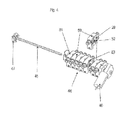
- Figure 1 illustrates an embodiment of an apparatus 1 for dispensing liquids, such as colorants for paints.
- This particular embodiment include a cabinet 2 accommodating a plurality of container assemblies 3 comprising a container 4 and a pump 5.
- the apparatus 1 further comprises a dispense head 6, a support 7 for a container located below the dispense head 6 and optionally provided with a weighing device, and electronic equipment (not shown) for driving the components of the apparatus 1.
- the dispense head 6 in turn comprises a manifold (hidden from view; known in itself) for dispensing a plurality of liquids.
- FIG 2A show a container assembly 3 as used in the apparatus 1 of Figure 1 .
- the container assembly 3 comprises a. container 4, in turn comprising a stirred 4A ( Figure 2B ), rotatable mounted inside the container 4, and connected via a rigid conduit 8 to a piston pump 5.
- the assembly 3 further comprises a pump conduit 9 connected to the pump 5 and a recirculation conduit 10 connected to the pump conduit 9 and to the container 4.
- the pump 5 comprises a disc-valve 11 operate by an electric motor 12 to selectively connect the pump 5 to the container 4 or to the pump conduit 9.
- the pump 5 comprises a piston rod 13 provided on one end with a piston 14, disposed within a cylinder 15.
- the other end of the piston, rod 13 comprises a threaded opening which cooperates with a spindle (not shown), which in turn is connected to or part of an electric motor 16 ( Figure 2A ).
- the piston rod 13 and the piston 14 are moved away from the valve 11 to draw in material from the container 4 or from the pump conduit 9, depending on the position of the valve 11.
- the pump 5 is capable of pumping the liquid from the container to the dispense conduit and in reverse direction.
- the recirculation conduit 10 comprises a first one-way valve 17 connecting it to the pump conduit 9, whereas the pump conduit 9 comprises a second one-way valve 18 downstream from the first one-way valve 17, connecting the pump conduit 9 to a dispense conduit 19.
- Both one-way valves 17, 18 open when liquid in the respective conduit 9, 10 is pumped in a direction away from the container 4.
- the first and second one-way valves 17, 18 and the connection of the recirculation conduit 10 to the dispense conduit 9 are integrated in a common housing 20.
- the second one-way valve 18 When liquid is withdrawn from the container 4 and pumped through the pump conduit 9, the second one-way valve 18 opens and the liquid is dispensed via the dispense conduit 19 to the dispense head 6. When the liquid is subsequently pumped in reverse direction, the second one-way valve 18 closes, the first one-way valve 17 opens, and liquid is withdrawn from the container 4 through the recirculation conduit 10.
- the first and second one-way valves 17, 18 are controlled and recirculation is established by reversing the flow direction of the liquid, without the need for a motor or actuator.
- the housing 20 may comprise a structure, such as a key way on one side of the housing and a corresponding key on the other side, which enables it to be attached to an identical housing.
- a plurality of housing can be grouped in one or more blocks.
- FIGs 3A and B show an alternative embodiment of a valve assembly 25 for a dispenser according to the present disclosure.
- the valve assembly 25 comprises a housing 26 with a circular cavity 27 at one side with an open end and a closed bottom, and a circular recess 29 at the opposite side ( Figure 4 ).
- the housing 25 comprises a back side 30 with a connection 31 to the pump conduit 9 and a connection 32 to the recirculation conduit 10.
- the housing 25 further comprises a front side 33 with a connection 34 to the dispense conduit 19 leading to the dispense head 6.
- Each of the three connections 31, 32, 34 opens into an eccentric smaller opening 35 in the housing wall, which leads to the cavity 27.
- the smaller opening 35 of the connection 31 for pump conduit 9 is in register with the upped half of the connection 31.
- the smaller openings of the other two connections are in register with the lower halves of the corresponding connections 32, 34.
- the cavity in the housing contains a disk 36 with a central non-circular (e.g., hexagonal) opening 37 and an eccentric flow-through opening 38.
- the disk 36 divides the cavity 27 into an upper part with an inlet chamber 39 in open connection with the pump conduit 9, and a lower part.
- the lower part comprises a first outlet chamber (not shown) in open connection with the dispense conduit 19 and a second outlet chamber (not shown) in open connection with the recirculation unit 10.
- the first and second outlet chamber are separated by an internal wall (not shown).
- the disk 36 can be rotated between a dispense position, ( Figure 3A ) and a recirculation position ( Figure 3B ).
- a dispense position ( Figure 3A ) and a recirculation position ( Figure 3B ).
- the dish 36 opens a flow path from the inlet chamber 39 via the flow through opening 38 and the first outlet chamber to the connection 34 of the dispense conduit 19.
- the disk 36 closes off the first outlet chamber and opens a flow path from the inlet chamber 39 via the flow through opening 38 and the second outlet chamber to the connection 32 of the recirculation conduit 10.
- the open side of the cavity 27 is closed off by a circular lid 40 which is attached to the housing by fastening means 41
- the lid 40 is provided with a circular central opening 42, which is in register with the non-circular central opening 37 in the disk 36 and a central circular opening (no shown) in the bottom of the housing.
- a bus 43 extends coaxially with the openings 37, 42 between the disk 36 and the lid 40.
- the bus 43 is pressed onto the disk 36 by means of a spring 48 acting onto a shoulder 49 of the bus 43. Sealing rings (not shown) are used to obtain a leak tight arrangement.
- valve assemblies 25 When the valve assemblies 25 are stacked and coupled to form a block 44, as shown in Figure 3 , the openings 37, 42 in the lids 40, disks 36 and housing bottoms are in line.
- a drive axle 45 extend through the openings 37, 42 to form a common actuator clamping the block 44 of stacked valve assembly, housings between a motor 46 at one end and an end plate 47 at the opposite end.
- the drive axle 45 has a non-circular contour matching in size and shape with the contour of the opening 37 in the disk 36.
- the motor 46 rotates the driving axle 45.
- the disks 36 of all valve assemblies 25 in the block 44 are rotated with the driving axle 45 and are simultaneously switched between the dispensing position and the recirculation position.
- the circular recess 29 at the housing side opposite to the cavity 27 comprises an extension 50 interrupting the upper face 51 of the housing.
- An indicator disk 52 is rotatable within the recess 29.
- the indicator disk 52 comprises a projection 53 projecting through the recess 50 interrupting the housing upper face 53.
- the indicator disk 52 is fixed to the drive axle 45. As a result, the indicator disk 52 rotates with the drive axle 45 and the valve disks 36. This way, the position of the indicator projection 53 informs a user whether the valve disks 36 are in the dispensing position or in the recirculation position.
Landscapes
- Chemical & Material Sciences (AREA)
- Chemical Kinetics & Catalysis (AREA)
- Engineering & Computer Science (AREA)
- General Engineering & Computer Science (AREA)
- Mechanical Engineering (AREA)
- Loading And Unloading Of Fuel Tanks Or Ships (AREA)
- Coating Apparatus (AREA)
- Devices For Dispensing Beverages (AREA)
- Nozzles (AREA)
Applications Claiming Priority (1)
| Application Number | Priority Date | Filing Date | Title |
|---|---|---|---|
| US13/073,252 US8783516B2 (en) | 2011-03-28 | 2011-03-28 | Liquid dispenser and method for preventing liquid segregation |
Publications (3)
| Publication Number | Publication Date |
|---|---|
| EP2505259A2 true EP2505259A2 (fr) | 2012-10-03 |
| EP2505259A3 EP2505259A3 (fr) | 2013-03-27 |
| EP2505259B1 EP2505259B1 (fr) | 2016-08-03 |
Family
ID=45952902
Family Applications (1)
| Application Number | Title | Priority Date | Filing Date |
|---|---|---|---|
| EP12161546.2A Not-in-force EP2505259B1 (fr) | 2011-03-28 | 2012-03-27 | Distributeur de liquide et procédé pour empêcher la ségrégation de liquide |
Country Status (3)
| Country | Link |
|---|---|
| US (1) | US8783516B2 (fr) |
| EP (1) | EP2505259B1 (fr) |
| CN (1) | CN102717979B (fr) |
Cited By (3)
| Publication number | Priority date | Publication date | Assignee | Title |
|---|---|---|---|---|
| EP2781257A1 (fr) * | 2013-03-18 | 2014-09-24 | Collomix Rühr-und Mischgeräte GmbH | Bidon pour fluides pouvant être pompés, notamment pour préparations de pigments colorés, dispositif de dosage et procédé de distribution de fluides pouvant être pompés |
| EP2957540A1 (fr) | 2014-06-18 | 2015-12-23 | Collomix Rühr-und Mischgeräte GmbH | Dispositif de dosage pour la distribution dosée de milieux pouvant être pompés, notamment de préparations de pigments colorés |
| CN113856545A (zh) * | 2021-10-25 | 2021-12-31 | 江苏振华新云电子有限公司 | 一种钽电容器专用碱液混合配置装置及配置方法 |
Families Citing this family (10)
| Publication number | Priority date | Publication date | Assignee | Title |
|---|---|---|---|---|
| IT1393787B1 (it) * | 2009-03-30 | 2012-05-08 | Cps Color Equipment Spa | Dispositivo di erogazione di prodotti fluidi e relativo procedimento di erogazione |
| US8936390B2 (en) * | 2011-12-16 | 2015-01-20 | Microblend Technologies, Inc. | Method and apparatus for producing paint |
| AU2017249317B2 (en) | 2016-04-11 | 2019-12-12 | Altopa, Inc. | Secure portable, on-demand, microfluidic mixing and dispensing device |
| US10981771B2 (en) | 2016-12-29 | 2021-04-20 | The Coca-Cola Company | Sold out detection using a level sensor for a beverage dispenser |
| USD802992S1 (en) | 2017-01-16 | 2017-11-21 | Altopa, Inc. | Blend machine |
| USD873068S1 (en) | 2017-07-16 | 2020-01-21 | Altopa, Inc. | Blend device |
| USD856745S1 (en) * | 2017-09-18 | 2019-08-20 | Integrated Roasting Technologies, Inc. | Roaster |
| IT201800010378A1 (it) * | 2018-11-16 | 2020-05-16 | Corob Spa | Apparecchiatura per erogare prodotti fluidi, in particolare liquidi |
| EP3712432B1 (fr) * | 2019-03-19 | 2024-07-17 | Fast & Fluid Management B.V. | Distributeur de liquide et procédé de fonctionnement d'un tel distributeur |
| DE102022104545A1 (de) | 2022-02-25 | 2023-08-31 | Denso Automotive Deutschland Gmbh | Kältemittelsammler-Modul für eine Wärmepumpenanordnung in einem Thermomanagementsystem für Fahrzeuge |
Citations (3)
| Publication number | Priority date | Publication date | Assignee | Title |
|---|---|---|---|---|
| US20020195462A1 (en) | 1997-10-13 | 2002-12-26 | Corob International Ag | Dispensing unit for a fluid dispensing machine, comprising a variable-volume pumping chamber, and machine comprising said dispensing unit |
| WO2004013036A1 (fr) | 2002-08-01 | 2004-02-12 | Cps Color Equipment S.P.A. | Circuit de distribution de fluides presentant des vannes de verification |
| EP1908510A2 (fr) | 2006-10-04 | 2008-04-09 | Dromont S.p.A. | Dispositif automatique pour mélanger des liquides, particulièrement des peintures ou des vernis |
Family Cites Families (15)
| Publication number | Priority date | Publication date | Assignee | Title |
|---|---|---|---|---|
| US2724581A (en) * | 1951-05-18 | 1955-11-22 | Crown Cork & Seal Co | Liquid proportioning system |
| US2787402A (en) * | 1952-04-16 | 1957-04-02 | Color Carousel Corp | Liquid proportioning and dispensing apparatus |
| US3172925A (en) * | 1962-08-31 | 1965-03-09 | Method of distributing foam forming resin within a sandwich structure | |
| US3424439A (en) * | 1967-11-29 | 1969-01-28 | Bert Baker | Device for mixing and applying foams |
| IT1227523B (it) * | 1988-12-06 | 1991-04-12 | Attilio Silvestri | Apparecchiatura per la regolazione dell'alimentazione contemporanea di piu' liquidi pigmentati in un impianto per la preparazione di prodotti vernicianti |
| US6082289A (en) * | 1995-08-24 | 2000-07-04 | Speedline Technologies, Inc. | Liquid dispensing system with controllably movable cartridge |
| CA2400748C (fr) * | 2000-03-31 | 2009-10-20 | Imx Labs, Inc. | Systeme et procede de selection de la couleur d'un vernis a ongles |
| ITTO20040012A1 (it) * | 2004-01-13 | 2004-04-13 | Nordimpianti Technologies S R | Tintometro |
| EP1799552A2 (fr) * | 2004-10-13 | 2007-06-27 | Ultrablend LLC | Procede et appareil de mise a la teinte |
| US20070289991A1 (en) * | 2006-06-20 | 2007-12-20 | Larry Jensen | Colorant Dispenser Having an Outlet Control Valve |
| US20080078782A1 (en) * | 2006-10-03 | 2008-04-03 | Bien Frank C | Rotary pump plural component applicator |
| US8240513B2 (en) * | 2008-03-24 | 2012-08-14 | Fluid Management Operations Llc | Fluid dispenser with nested displacement members |
| EP2198950B1 (fr) * | 2008-12-19 | 2011-10-12 | Fluid Management Operations LLC | Appareil pour distribuer plusieurs fluides |
| US8224481B2 (en) * | 2009-01-19 | 2012-07-17 | Access Business Group International Llc | Method and apparatus for dispensing fluid compositions |
| US8256647B2 (en) * | 2009-02-13 | 2012-09-04 | Fluid Management Operations Llc | Valve assembly for dispensing flowable materials |
-
2011
- 2011-03-28 US US13/073,252 patent/US8783516B2/en active Active
-
2012
- 2012-03-27 EP EP12161546.2A patent/EP2505259B1/fr not_active Not-in-force
- 2012-03-28 CN CN201210188918.4A patent/CN102717979B/zh active Active
Patent Citations (3)
| Publication number | Priority date | Publication date | Assignee | Title |
|---|---|---|---|---|
| US20020195462A1 (en) | 1997-10-13 | 2002-12-26 | Corob International Ag | Dispensing unit for a fluid dispensing machine, comprising a variable-volume pumping chamber, and machine comprising said dispensing unit |
| WO2004013036A1 (fr) | 2002-08-01 | 2004-02-12 | Cps Color Equipment S.P.A. | Circuit de distribution de fluides presentant des vannes de verification |
| EP1908510A2 (fr) | 2006-10-04 | 2008-04-09 | Dromont S.p.A. | Dispositif automatique pour mélanger des liquides, particulièrement des peintures ou des vernis |
Cited By (4)
| Publication number | Priority date | Publication date | Assignee | Title |
|---|---|---|---|---|
| EP2781257A1 (fr) * | 2013-03-18 | 2014-09-24 | Collomix Rühr-und Mischgeräte GmbH | Bidon pour fluides pouvant être pompés, notamment pour préparations de pigments colorés, dispositif de dosage et procédé de distribution de fluides pouvant être pompés |
| EP2957540A1 (fr) | 2014-06-18 | 2015-12-23 | Collomix Rühr-und Mischgeräte GmbH | Dispositif de dosage pour la distribution dosée de milieux pouvant être pompés, notamment de préparations de pigments colorés |
| CN113856545A (zh) * | 2021-10-25 | 2021-12-31 | 江苏振华新云电子有限公司 | 一种钽电容器专用碱液混合配置装置及配置方法 |
| CN113856545B (zh) * | 2021-10-25 | 2023-09-12 | 江苏振华新云电子有限公司 | 一种钽电容器专用碱液混合配置装置及配置方法 |
Also Published As
| Publication number | Publication date |
|---|---|
| EP2505259B1 (fr) | 2016-08-03 |
| CN102717979B (zh) | 2016-08-17 |
| US20120248137A1 (en) | 2012-10-04 |
| CN102717979A (zh) | 2012-10-10 |
| US8783516B2 (en) | 2014-07-22 |
| EP2505259A3 (fr) | 2013-03-27 |
Similar Documents
| Publication | Publication Date | Title |
|---|---|---|
| EP2505259A2 (fr) | Distributeur de liquide et procédé pour empêcher la ségrégation de liquide | |
| DE60004201T2 (de) | Vorrichtung und verfahren zur herstellung individueller kosmetikprodukte | |
| JP4634393B2 (ja) | 重量計量方式と体積計量方式とを併用して複数の流体状材料を計量供給するディスペンサ | |
| US9724658B2 (en) | Method of homogenizing a liquid | |
| EP2218948B1 (fr) | Ensemble de valve et appareil pour la distribution de matériaux fluides | |
| WO2008084234A3 (fr) | Distributeur de boisson | |
| CN105026307B (zh) | 分配阀组件以及用于调色机的色浆分配装置 | |
| CN106573262B (zh) | 用于配量分配器的放出头和配量分配器 | |
| EP3094226A1 (fr) | Appareil distributeur destiné à distribuer du savon liquide, une lotion ou d'autres liquides | |
| CN103328171A (zh) | 用于对液态的颜料和/或功能添加剂进行配量和/或馈入的设备和方法 | |
| US11890588B2 (en) | Personal cosmetic dispenser | |
| US11845050B2 (en) | System and method for producing a mixture of liquids | |
| CN108014716A (zh) | 分配装置和用于该分配装置的可释放地连接的流体容器 | |
| WO2015183775A1 (fr) | Pompes à mousse à double chambre à air, unités de recharge et distributeurs | |
| WO2014193885A2 (fr) | Pompes à mousse à amorçage par le vide, unités de recharge et distributeurs | |
| US10948326B2 (en) | Soap, sanitizer and lotion dispensers having adjustable volume outputs | |
| ES2586816T3 (es) | Máquina de tintura | |
| US20230069971A1 (en) | Device for dispensing and dosing powdery or pasty or liquid materials | |
| AT508090A1 (de) | Spender für fliessfähiges medium | |
| US3205825A (en) | Proportioning pump | |
| US12514409B2 (en) | Sequentially activated multi-diaphragm foam at-a-distance dispenser systems | |
| CN203272047U (zh) | 用于调色机的定量泵驱动装置 | |
| IT201800006192A1 (it) | Macchina e procedimento per erogare prodotti fluidi, in particolare liquidi coloranti | |
| JP2022538766A (ja) | 流体製品を分注するための分注機構、装置及び方法 | |
| CN221558260U (zh) | 一种自动色浆调配机器 |
Legal Events
| Date | Code | Title | Description |
|---|---|---|---|
| PUAI | Public reference made under article 153(3) epc to a published international application that has entered the european phase |
Free format text: ORIGINAL CODE: 0009012 |
|
| AK | Designated contracting states |
Kind code of ref document: A2 Designated state(s): AL AT BE BG CH CY CZ DE DK EE ES FI FR GB GR HR HU IE IS IT LI LT LU LV MC MK MT NL NO PL PT RO RS SE SI SK SM TR |
|
| AX | Request for extension of the european patent |
Extension state: BA ME |
|
| RIC1 | Information provided on ipc code assigned before grant |
Ipc: B01F 15/02 20060101ALI20121017BHEP Ipc: B01F 13/10 20060101AFI20121017BHEP Ipc: F16K 11/074 20060101ALI20121017BHEP |
|
| PUAL | Search report despatched |
Free format text: ORIGINAL CODE: 0009013 |
|
| AK | Designated contracting states |
Kind code of ref document: A3 Designated state(s): AL AT BE BG CH CY CZ DE DK EE ES FI FR GB GR HR HU IE IS IT LI LT LU LV MC MK MT NL NO PL PT RO RS SE SI SK SM TR |
|
| AX | Request for extension of the european patent |
Extension state: BA ME |
|
| RIC1 | Information provided on ipc code assigned before grant |
Ipc: F16K 11/074 20060101ALI20130215BHEP Ipc: B01F 15/02 20060101ALI20130215BHEP Ipc: B01F 13/10 20060101AFI20130215BHEP |
|
| 17P | Request for examination filed |
Effective date: 20130807 |
|
| RBV | Designated contracting states (corrected) |
Designated state(s): AL AT BE BG CH CY CZ DE DK EE ES FI FR GB GR HR HU IE IS IT LI LT LU LV MC MK MT NL NO PL PT RO RS SE SI SK SM TR |
|
| 17Q | First examination report despatched |
Effective date: 20131217 |
|
| GRAP | Despatch of communication of intention to grant a patent |
Free format text: ORIGINAL CODE: EPIDOSNIGR1 |
|
| INTG | Intention to grant announced |
Effective date: 20160226 |
|
| GRAS | Grant fee paid |
Free format text: ORIGINAL CODE: EPIDOSNIGR3 |
|
| GRAA | (expected) grant |
Free format text: ORIGINAL CODE: 0009210 |
|
| AK | Designated contracting states |
Kind code of ref document: B1 Designated state(s): AL AT BE BG CH CY CZ DE DK EE ES FI FR GB GR HR HU IE IS IT LI LT LU LV MC MK MT NL NO PL PT RO RS SE SI SK SM TR |
|
| REG | Reference to a national code |
Ref country code: GB Ref legal event code: FG4D |
|
| REG | Reference to a national code |
Ref country code: CH Ref legal event code: EP Ref country code: AT Ref legal event code: REF Ref document number: 816982 Country of ref document: AT Kind code of ref document: T Effective date: 20160815 |
|
| REG | Reference to a national code |
Ref country code: IE Ref legal event code: FG4D |
|
| REG | Reference to a national code |
Ref country code: DE Ref legal event code: R096 Ref document number: 602012021151 Country of ref document: DE |
|
| REG | Reference to a national code |
Ref country code: NL Ref legal event code: FP |
|
| REG | Reference to a national code |
Ref country code: LT Ref legal event code: MG4D |
|
| REG | Reference to a national code |
Ref country code: AT Ref legal event code: MK05 Ref document number: 816982 Country of ref document: AT Kind code of ref document: T Effective date: 20160803 |
|
| PG25 | Lapsed in a contracting state [announced via postgrant information from national office to epo] |
Ref country code: LT Free format text: LAPSE BECAUSE OF FAILURE TO SUBMIT A TRANSLATION OF THE DESCRIPTION OR TO PAY THE FEE WITHIN THE PRESCRIBED TIME-LIMIT Effective date: 20160803 Ref country code: HR Free format text: LAPSE BECAUSE OF FAILURE TO SUBMIT A TRANSLATION OF THE DESCRIPTION OR TO PAY THE FEE WITHIN THE PRESCRIBED TIME-LIMIT Effective date: 20160803 Ref country code: IS Free format text: LAPSE BECAUSE OF FAILURE TO SUBMIT A TRANSLATION OF THE DESCRIPTION OR TO PAY THE FEE WITHIN THE PRESCRIBED TIME-LIMIT Effective date: 20161203 Ref country code: FI Free format text: LAPSE BECAUSE OF FAILURE TO SUBMIT A TRANSLATION OF THE DESCRIPTION OR TO PAY THE FEE WITHIN THE PRESCRIBED TIME-LIMIT Effective date: 20160803 Ref country code: NO Free format text: LAPSE BECAUSE OF FAILURE TO SUBMIT A TRANSLATION OF THE DESCRIPTION OR TO PAY THE FEE WITHIN THE PRESCRIBED TIME-LIMIT Effective date: 20161103 Ref country code: RS Free format text: LAPSE BECAUSE OF FAILURE TO SUBMIT A TRANSLATION OF THE DESCRIPTION OR TO PAY THE FEE WITHIN THE PRESCRIBED TIME-LIMIT Effective date: 20160803 |
|
| PG25 | Lapsed in a contracting state [announced via postgrant information from national office to epo] |
Ref country code: PT Free format text: LAPSE BECAUSE OF FAILURE TO SUBMIT A TRANSLATION OF THE DESCRIPTION OR TO PAY THE FEE WITHIN THE PRESCRIBED TIME-LIMIT Effective date: 20161205 Ref country code: ES Free format text: LAPSE BECAUSE OF FAILURE TO SUBMIT A TRANSLATION OF THE DESCRIPTION OR TO PAY THE FEE WITHIN THE PRESCRIBED TIME-LIMIT Effective date: 20160803 Ref country code: AT Free format text: LAPSE BECAUSE OF FAILURE TO SUBMIT A TRANSLATION OF THE DESCRIPTION OR TO PAY THE FEE WITHIN THE PRESCRIBED TIME-LIMIT Effective date: 20160803 Ref country code: SE Free format text: LAPSE BECAUSE OF FAILURE TO SUBMIT A TRANSLATION OF THE DESCRIPTION OR TO PAY THE FEE WITHIN THE PRESCRIBED TIME-LIMIT Effective date: 20160803 Ref country code: GR Free format text: LAPSE BECAUSE OF FAILURE TO SUBMIT A TRANSLATION OF THE DESCRIPTION OR TO PAY THE FEE WITHIN THE PRESCRIBED TIME-LIMIT Effective date: 20161104 Ref country code: LV Free format text: LAPSE BECAUSE OF FAILURE TO SUBMIT A TRANSLATION OF THE DESCRIPTION OR TO PAY THE FEE WITHIN THE PRESCRIBED TIME-LIMIT Effective date: 20160803 Ref country code: PL Free format text: LAPSE BECAUSE OF FAILURE TO SUBMIT A TRANSLATION OF THE DESCRIPTION OR TO PAY THE FEE WITHIN THE PRESCRIBED TIME-LIMIT Effective date: 20160803 |
|
| RAP2 | Party data changed (patent owner data changed or rights of a patent transferred) |
Owner name: FAST & FLUID MANAGEMENT B.V. |
|
| REG | Reference to a national code |
Ref country code: DE Ref legal event code: R081 Ref document number: 602012021151 Country of ref document: DE Owner name: FAST & FLUID MANAGEMENT B.V., NL Free format text: FORMER OWNER: FLUID MANAGEMENT OPERATIONS LLC, WHEELING, ILL., US |
|
| REG | Reference to a national code |
Ref country code: FR Ref legal event code: PLFP Year of fee payment: 6 |
|
| REG | Reference to a national code |
Ref country code: NL Ref legal event code: PD Owner name: FAST & FLUID MANAGEMENT B.V.; NL Free format text: DETAILS ASSIGNMENT: CHANGE OF OWNER(S), ASSIGNMENT; FORMER OWNER NAME: FLUID MANAGEMENT OPERATIONS LLC Effective date: 20170308 |
|
| PG25 | Lapsed in a contracting state [announced via postgrant information from national office to epo] |
Ref country code: EE Free format text: LAPSE BECAUSE OF FAILURE TO SUBMIT A TRANSLATION OF THE DESCRIPTION OR TO PAY THE FEE WITHIN THE PRESCRIBED TIME-LIMIT Effective date: 20160803 Ref country code: RO Free format text: LAPSE BECAUSE OF FAILURE TO SUBMIT A TRANSLATION OF THE DESCRIPTION OR TO PAY THE FEE WITHIN THE PRESCRIBED TIME-LIMIT Effective date: 20160803 |
|
| REG | Reference to a national code |
Ref country code: DE Ref legal event code: R097 Ref document number: 602012021151 Country of ref document: DE |
|
| PG25 | Lapsed in a contracting state [announced via postgrant information from national office to epo] |
Ref country code: DK Free format text: LAPSE BECAUSE OF FAILURE TO SUBMIT A TRANSLATION OF THE DESCRIPTION OR TO PAY THE FEE WITHIN THE PRESCRIBED TIME-LIMIT Effective date: 20160803 Ref country code: BE Free format text: LAPSE BECAUSE OF FAILURE TO SUBMIT A TRANSLATION OF THE DESCRIPTION OR TO PAY THE FEE WITHIN THE PRESCRIBED TIME-LIMIT Effective date: 20160803 Ref country code: SM Free format text: LAPSE BECAUSE OF FAILURE TO SUBMIT A TRANSLATION OF THE DESCRIPTION OR TO PAY THE FEE WITHIN THE PRESCRIBED TIME-LIMIT Effective date: 20160803 Ref country code: CZ Free format text: LAPSE BECAUSE OF FAILURE TO SUBMIT A TRANSLATION OF THE DESCRIPTION OR TO PAY THE FEE WITHIN THE PRESCRIBED TIME-LIMIT Effective date: 20160803 Ref country code: BG Free format text: LAPSE BECAUSE OF FAILURE TO SUBMIT A TRANSLATION OF THE DESCRIPTION OR TO PAY THE FEE WITHIN THE PRESCRIBED TIME-LIMIT Effective date: 20161103 Ref country code: SK Free format text: LAPSE BECAUSE OF FAILURE TO SUBMIT A TRANSLATION OF THE DESCRIPTION OR TO PAY THE FEE WITHIN THE PRESCRIBED TIME-LIMIT Effective date: 20160803 |
|
| PLBE | No opposition filed within time limit |
Free format text: ORIGINAL CODE: 0009261 |
|
| STAA | Information on the status of an ep patent application or granted ep patent |
Free format text: STATUS: NO OPPOSITION FILED WITHIN TIME LIMIT |
|
| REG | Reference to a national code |
Ref country code: GB Ref legal event code: 732E Free format text: REGISTERED BETWEEN 20170518 AND 20170524 |
|
| 26N | No opposition filed |
Effective date: 20170504 |
|
| PG25 | Lapsed in a contracting state [announced via postgrant information from national office to epo] |
Ref country code: SI Free format text: LAPSE BECAUSE OF FAILURE TO SUBMIT A TRANSLATION OF THE DESCRIPTION OR TO PAY THE FEE WITHIN THE PRESCRIBED TIME-LIMIT Effective date: 20160803 |
|
| REG | Reference to a national code |
Ref country code: CH Ref legal event code: PL |
|
| PG25 | Lapsed in a contracting state [announced via postgrant information from national office to epo] |
Ref country code: MC Free format text: LAPSE BECAUSE OF FAILURE TO SUBMIT A TRANSLATION OF THE DESCRIPTION OR TO PAY THE FEE WITHIN THE PRESCRIBED TIME-LIMIT Effective date: 20160803 |
|
| REG | Reference to a national code |
Ref country code: IE Ref legal event code: MM4A |
|
| PG25 | Lapsed in a contracting state [announced via postgrant information from national office to epo] |
Ref country code: LU Free format text: LAPSE BECAUSE OF NON-PAYMENT OF DUE FEES Effective date: 20170327 |
|
| PG25 | Lapsed in a contracting state [announced via postgrant information from national office to epo] |
Ref country code: LI Free format text: LAPSE BECAUSE OF NON-PAYMENT OF DUE FEES Effective date: 20170331 Ref country code: IE Free format text: LAPSE BECAUSE OF NON-PAYMENT OF DUE FEES Effective date: 20170327 Ref country code: CH Free format text: LAPSE BECAUSE OF NON-PAYMENT OF DUE FEES Effective date: 20170331 |
|
| REG | Reference to a national code |
Ref country code: FR Ref legal event code: PLFP Year of fee payment: 7 |
|
| PG25 | Lapsed in a contracting state [announced via postgrant information from national office to epo] |
Ref country code: MT Free format text: LAPSE BECAUSE OF NON-PAYMENT OF DUE FEES Effective date: 20170327 |
|
| PG25 | Lapsed in a contracting state [announced via postgrant information from national office to epo] |
Ref country code: AL Free format text: LAPSE BECAUSE OF FAILURE TO SUBMIT A TRANSLATION OF THE DESCRIPTION OR TO PAY THE FEE WITHIN THE PRESCRIBED TIME-LIMIT Effective date: 20160803 |
|
| PG25 | Lapsed in a contracting state [announced via postgrant information from national office to epo] |
Ref country code: HU Free format text: LAPSE BECAUSE OF FAILURE TO SUBMIT A TRANSLATION OF THE DESCRIPTION OR TO PAY THE FEE WITHIN THE PRESCRIBED TIME-LIMIT; INVALID AB INITIO Effective date: 20120327 |
|
| PG25 | Lapsed in a contracting state [announced via postgrant information from national office to epo] |
Ref country code: CY Free format text: LAPSE BECAUSE OF NON-PAYMENT OF DUE FEES Effective date: 20160803 |
|
| PG25 | Lapsed in a contracting state [announced via postgrant information from national office to epo] |
Ref country code: MK Free format text: LAPSE BECAUSE OF FAILURE TO SUBMIT A TRANSLATION OF THE DESCRIPTION OR TO PAY THE FEE WITHIN THE PRESCRIBED TIME-LIMIT Effective date: 20160803 |
|
| PG25 | Lapsed in a contracting state [announced via postgrant information from national office to epo] |
Ref country code: TR Free format text: LAPSE BECAUSE OF FAILURE TO SUBMIT A TRANSLATION OF THE DESCRIPTION OR TO PAY THE FEE WITHIN THE PRESCRIBED TIME-LIMIT Effective date: 20160803 |
|
| PGFP | Annual fee paid to national office [announced via postgrant information from national office to epo] |
Ref country code: GB Payment date: 20200323 Year of fee payment: 9 Ref country code: DE Payment date: 20200320 Year of fee payment: 9 Ref country code: NL Payment date: 20200319 Year of fee payment: 9 |
|
| PGFP | Annual fee paid to national office [announced via postgrant information from national office to epo] |
Ref country code: FR Payment date: 20200320 Year of fee payment: 9 |
|
| PGFP | Annual fee paid to national office [announced via postgrant information from national office to epo] |
Ref country code: IT Payment date: 20200318 Year of fee payment: 9 |
|
| REG | Reference to a national code |
Ref country code: DE Ref legal event code: R119 Ref document number: 602012021151 Country of ref document: DE |
|
| REG | Reference to a national code |
Ref country code: NL Ref legal event code: MM Effective date: 20210401 |
|
| GBPC | Gb: european patent ceased through non-payment of renewal fee |
Effective date: 20210327 |
|
| PG25 | Lapsed in a contracting state [announced via postgrant information from national office to epo] |
Ref country code: NL Free format text: LAPSE BECAUSE OF NON-PAYMENT OF DUE FEES Effective date: 20210401 Ref country code: GB Free format text: LAPSE BECAUSE OF NON-PAYMENT OF DUE FEES Effective date: 20210327 Ref country code: FR Free format text: LAPSE BECAUSE OF NON-PAYMENT OF DUE FEES Effective date: 20210331 Ref country code: DE Free format text: LAPSE BECAUSE OF NON-PAYMENT OF DUE FEES Effective date: 20211001 |
|
| PG25 | Lapsed in a contracting state [announced via postgrant information from national office to epo] |
Ref country code: IT Free format text: LAPSE BECAUSE OF NON-PAYMENT OF DUE FEES Effective date: 20210327 |