EP2504530B1 - turbocompresseur - Google Patents
turbocompresseur Download PDFInfo
- Publication number
- EP2504530B1 EP2504530B1 EP10778987.7A EP10778987A EP2504530B1 EP 2504530 B1 EP2504530 B1 EP 2504530B1 EP 10778987 A EP10778987 A EP 10778987A EP 2504530 B1 EP2504530 B1 EP 2504530B1
- Authority
- EP
- European Patent Office
- Prior art keywords
- bearing
- recess
- shaft
- diameter
- bearing shaft
- Prior art date
- Legal status (The legal status is an assumption and is not a legal conclusion. Google has not performed a legal analysis and makes no representation as to the accuracy of the status listed.)
- Not-in-force
Links
- 230000008859 change Effects 0.000 claims description 12
- 238000001746 injection moulding Methods 0.000 claims description 4
- 239000000853 adhesive Substances 0.000 claims 1
- 230000001070 adhesive effect Effects 0.000 claims 1
- 238000004519 manufacturing process Methods 0.000 description 9
- 238000002485 combustion reaction Methods 0.000 description 7
- 238000000034 method Methods 0.000 description 4
- 238000002347 injection Methods 0.000 description 3
- 239000007924 injection Substances 0.000 description 3
- 230000008901 benefit Effects 0.000 description 2
- 230000000694 effects Effects 0.000 description 2
- 239000000463 material Substances 0.000 description 2
- 238000012805 post-processing Methods 0.000 description 2
- 230000009467 reduction Effects 0.000 description 2
- 230000015572 biosynthetic process Effects 0.000 description 1
- 238000005266 casting Methods 0.000 description 1
- 230000007423 decrease Effects 0.000 description 1
- 230000003247 decreasing effect Effects 0.000 description 1
- 238000005553 drilling Methods 0.000 description 1
- 230000006872 improvement Effects 0.000 description 1
- 238000005495 investment casting Methods 0.000 description 1
- 230000008569 process Effects 0.000 description 1
- 230000004044 response Effects 0.000 description 1
- 238000007493 shaping process Methods 0.000 description 1
- 125000006850 spacer group Chemical group 0.000 description 1
Images


Classifications
-
- F—MECHANICAL ENGINEERING; LIGHTING; HEATING; WEAPONS; BLASTING
- F01—MACHINES OR ENGINES IN GENERAL; ENGINE PLANTS IN GENERAL; STEAM ENGINES
- F01D—NON-POSITIVE DISPLACEMENT MACHINES OR ENGINES, e.g. STEAM TURBINES
- F01D17/00—Regulating or controlling by varying flow
- F01D17/10—Final actuators
- F01D17/12—Final actuators arranged in stator parts
- F01D17/14—Final actuators arranged in stator parts varying effective cross-sectional area of nozzles or guide conduits
- F01D17/16—Final actuators arranged in stator parts varying effective cross-sectional area of nozzles or guide conduits by means of nozzle vanes
- F01D17/165—Final actuators arranged in stator parts varying effective cross-sectional area of nozzles or guide conduits by means of nozzle vanes for radial flow, i.e. the vanes turning around axes which are essentially parallel to the rotor centre line
-
- F—MECHANICAL ENGINEERING; LIGHTING; HEATING; WEAPONS; BLASTING
- F02—COMBUSTION ENGINES; HOT-GAS OR COMBUSTION-PRODUCT ENGINE PLANTS
- F02C—GAS-TURBINE PLANTS; AIR INTAKES FOR JET-PROPULSION PLANTS; CONTROLLING FUEL SUPPLY IN AIR-BREATHING JET-PROPULSION PLANTS
- F02C6/00—Plural gas-turbine plants; Combinations of gas-turbine plants with other apparatus; Adaptations of gas-turbine plants for special use
- F02C6/04—Gas-turbine plants providing heated or pressurised working fluid for other apparatus, e.g. without mechanical power output
- F02C6/10—Gas-turbine plants providing heated or pressurised working fluid for other apparatus, e.g. without mechanical power output supplying working fluid to a user, e.g. a chemical process, which returns working fluid to a turbine of the plant
- F02C6/12—Turbochargers, i.e. plants for augmenting mechanical power output of internal-combustion piston engines by increase of charge pressure
-
- F—MECHANICAL ENGINEERING; LIGHTING; HEATING; WEAPONS; BLASTING
- F05—INDEXING SCHEMES RELATING TO ENGINES OR PUMPS IN VARIOUS SUBCLASSES OF CLASSES F01-F04
- F05D—INDEXING SCHEME FOR ASPECTS RELATING TO NON-POSITIVE-DISPLACEMENT MACHINES OR ENGINES, GAS-TURBINES OR JET-PROPULSION PLANTS
- F05D2220/00—Application
- F05D2220/40—Application in turbochargers
Definitions
- the invention relates to an exhaust gas turbocharger of a vehicle, comprising a turbine, which has at least one flow guide vane for a medium, wherein the flow vane is pivotably mounted on a housing component of the charging device by means of a bearing shaft located in a recess of the housing component.
- the flow cross-section is adapted, for example, to the operating state of the internal combustion engine and / or the charging device in order to achieve a reduction in consumption or emissions.
- the change in the flow cross section serves to adapt the Aufstau s the turbine.
- the Strömungsleitschaufel is rotatably or pivotally mounted on the housing component - which can also be referred to as a bearing plate - attached.
- the aim is to store the guide vane such that jamming occurs over a lifetime of the charging device the flow vane is prevented, so that a smooth adjustment is guaranteed.
- the Strömungsleitschaufel should perform so far a defined movement within the turbine flowing through the exhaust stream.
- the flow guide vanes are actuated via an adjusting device, wherein a force required for adjustment is introduced from outside a housing of the charging device.
- the Strömungsleitschaufel is supported by means of the bearing shaft, wherein the latter engages in the recess of the housing component. From the prior art, it is known to make constant the diameter of the bearing shaft over the entire length of the bearing shaft or to provide the bearing shaft with a constriction so that it is not in contact with an inner wall of the recess at this point. In this way, the smooth running of the bearing shaft can be improved.
- the US 3,033,519 A shows an exhaust gas turbocharger with flow guide vanes, which are mounted on a mounted in a recess of a housing component of the exhaust gas turbocharger bearing shaft.
- the recess has a stepped shape.
- an exhaust gas turbocharger with flow vanes From the EP 1 811 135 A1 is known an exhaust gas turbocharger with flow vanes.
- the Strömungsleitshaufeln are rotatably mounted on a bearing shaft, wherein the bearing shaft is mounted in a bush which is arranged in a recess of a housing of the exhaust gas turbocharger.
- the DE 197 52 534 C1 describes an exhaust gas turbocharger with flow guide vanes which are rotatable by means of a bearing shaft which is mounted in a recess of a housing of the exhaust gas turbocharger.
- the recess has a stepped shape.
- the exhaust gas turbocharger with the features mentioned in claim 1 has the advantage that a simpler and more cost-effective production is possible and in particular injection molding can be used without slide tools for demolding the bearing shaft are necessary.
- the bearing shaft and the recess form at least two axially spaced apart bearings with different diameters.
- Both the recess of the housing component and the bearing shaft preferably have a round cross-section. Together they train the at least two camps. It is provided that the bearing shaft and the inner wall of the recess are in contact with each other at most in the region of the bearing point.
- the diameter of the bearing shaft is referred to as shaft diameter and the diameter of the recess as a recess diameter. It is irrelevant whether shaft diameter and / or recess diameter of the bearings differ from each other. It can be provided both that the shaft diameter remains constant over the entire length of the bearing shaft, while the recess diameter changes in order to achieve the different diameter of the bearings, as well as that the shaft diameter changes while the recess diameter remains constant.
- both the shaft diameter and the recess diameter change. It is thus provided that the bearing shaft has different shaft diameters at the bearing points and the recess can have different recess diameters at the bearing points.
- the flow guide blade or the bearing shaft can be produced using shaping manufacturing methods, without the need for reworking, such as grinding, for example. Preference is given to a MIM or a similar process.
- the bearings are with the different Diameters due to a continuous change of the shaft diameter educated. In this way, a slide tool can be omitted, which is otherwise necessary for demolding the bearing shaft from a mold used for the production.
- a development of the invention provides that the bearing point, which has the larger diameter, is arranged on the side facing the Strömungsleitschaufel. Starting from the flow vane thus reduces the diameter of the bearing.
- the different diameters of the bearing points are formed by different shaft diameters, the demolding of the flow guide vane or the bearing shaft can be facilitated in this way.
- a continuous change of the shaft diameter and / or the recess diameter is provided between the bearings.
- a sudden change in the shaft diameter or the recess diameter is avoided in order to keep the notch effect as small as possible. Due to a sudden change in diameter, a local stress concentration could occur at the affected area, which would significantly increase the material stress at this point. For this reason, the continuous change in diameter is provided according to the invention.
- a development of the invention provides that between the bearings a continuous change of the recess diameter is provided.
- a sudden change in the recess diameter is avoided in order to keep the notch effect as small as possible. Due to a sudden change in diameter, a local stress concentration could occur at the affected area, which would significantly increase the material stress at this point. For this reason, the continuous diameter change is preferably provided.
- a development of the invention provides that in the region of at least one of the bearing points of the recess diameter substantially corresponds to the shaft diameter.
- the bearing shaft is mounted directly on the housing component in this area, so it is in touching contact with this. It is therefore not necessary to provide an additional intermediate element between the bearing shaft and the inner wall of the recess in order to form the bearing point.
- the shaft diameter is slightly smaller than the recess diameter to allow a smooth adjustment of the flow vanes by means of the bearing shaft.
- the bearing shaft is assigned at least one bearing element.
- the bearing element is arranged in the region of the bearing or assigned to this, so that the bearing element can form the bearing at least with.
- the bearing element may be present as a ring element, which is fastened on the bearing shaft or in the recess. With such a ring element is achieved that the Recess diameter over the length of the recess can be kept constant, while the different diameters of the bearings are realized with different shaft diameters.
- the bearing element is part of an adjusting device for the bearing shaft, so that the adjusting device at least partially cooperates with the bearing shaft and the recess to form the bearing point.
- the bearing element is part of an adjusting lever of the adjusting device. This adjustment lever is used to apply a torque to the bearing shaft and thus to adjust the flow vane. It is now provided that the bearing element engages around the bearing shaft at least partially and at the same time engages in the recess. In this way, in turn, the recess diameter remain constant and different shaft diameters are present to form the different diameters of the bearings.
- a development of the invention provides that the bearing shaft and the guide blade are produced as a common component, in particular by means of an injection molding process. Such a procedure is particularly preferred if the bearing shaft has a shaft diameter which decreases starting from the flow guide vane. In this case, a slide tool for removal from the mold can be omitted in the production of the component, so that both the production of the common component and the provision of the injection mold for the production of the component are easier and cheaper to accomplish.
- the FIG. 1 shows a charging device 1 with a turbine 2, in particular exhaust gas turbine, which has a turbine wheel 3.
- the turbine wheel 3 is flowed radially via a Verstellschaufelsystem 4, an outflow from the turbine wheel 3 takes place axially (in FIG. 1 to the right).
- the adjusting blade system 4 has at least one flow guide vane 5 which is arranged in the flow path of the exhaust gas flowing onto the turbine wheel 3.
- the Strömungsleitschaufel 5 is pivotally mounted by means of a bearing shaft 6.
- the bearing shaft 6 is seated in a recess 7 of a housing part 8 - which is part of a housing 9 of the turbine 2 - a.
- the housing component 8 is, for example, a bearing disk 10 of the charging device 1.
- a cover disk 11 Opposite the bearing disk 10, a cover disk 11 is provided. Between bearing disc 10 and cover plate 11, the Strömungsleitschaufel 5 is arranged. To adjust the flow vane a sufficient distance between the bearing plate 10 and cover plate 11 is necessary. To ensure this, a spacer 12 between the bearing plate 10 and cover plate 11 is additionally provided.
- the Strömungsleitschaufel 5 preferably has both of the bearing plate 10 and the cover plate 11 at a small distance to allow in this way a reliable and smooth adjustment of the Strömungsschschelel 5.
- an adjusting device 13 is provided and rotatably connected to the bearing shaft 6.
- a torque can be applied to the bearing shaft 6 and thus the Strömungsleitschaufel 5 are adjusted.
- an angle of incidence of the turbine wheel 3 corresponding to a load state of an internal combustion engine (not shown) assigned to the supercharger 1 can be adjusted.
- the flow cross-section in a flow channel 14 in which the flow guide vane 5 is arranged can be reduced. In this way, the flow velocity of the turbine wheel 3, despite low exhaust gas mass flow through the charging device 1 and the turbine 2 is sufficiently high to drive the turbine wheel 3.
- the flow cross-section of the flow channel 14 is increased, so that the turbine 2 generates no unnecessarily high flow resistance or pressure loss and the energy contained in the exhaust gas is advantageous for driving the turbine wheel 3 available ,
- the turbine wheel 3 driven by the exhaust gas drives, via a shaft 15, a compressor wheel (not shown) of the charging device 1.
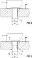
- FIG. 2 shows a first, known from the prior art embodiment of the Strömungsleitschaufel 5 with the bearing shaft 6.
- the latter is, as already described above, rotatably mounted in the recess 7 of the housing member 8 and the bearing plate 10.
- the recess 7 has a constant recess diameter d 1
- the bearing shaft 6 has a constant bearing shaft diameter d 2 . It is provided that the bearing shaft diameter substantially corresponds to the recess diameter or is slightly smaller, so that a smooth adjustment of the Strömungsleitschaufel 5 is ensured by means of the bearing shaft 6.
- FIG. 3 shows a second, known from the prior art embodiment of the Strömungsleitschaufel 5 and the bearing shaft 6.
- the bearing shaft 6 is mounted in the recess 7 of the housing member 8.
- the recess diameter d 1 is constant.
- the shaft diameter d 2 is substantially constant.
- the bearing shaft 6 in one area has a constriction 16 so that the diameter is reduced here (in FIG. 3 indicated by the dashed lines).
- the rotational resistance of the bearing shaft so the torque, which counteracts an adjusting moment used for adjusting the flow vane 5, can be reduced, since the bearing surface of the bearing shaft 6 is reduced on the inner wall of the recess 7.
- the FIG. 4 shows a first embodiment according to the invention of the Strömungsleitschaufel 5 and the bearing shaft 6. It is clear that as well as in the embodiment of FIG. 3 two bearings 17 and 18 are present. In contrast to the aforementioned embodiment, however, the bearings 17 and 18 have different diameters.
- the diameter can be defined, for example, with the diameter at which the bearing shaft 6 with the inner wall of the recess 7 to form the bearings 17 and 18 comes into touching contact.
- the diameter of the bearing points 17 and 18 with the shaft diameter in the area of the bearing points 17 and 18 can be assumed. Alternatively, the diameter may also be defined as the mean value of the shaft diameter and the recess diameter.
- the recess 7 is a stepped recess 19 or stepped bore. This can be easily produced by performing two drilling operations with different diameters. It is provided that the bearing shaft 6 in the region of the first bearing 17, which is located on the side of the bearing shaft 6 facing the Strömungsleitschaufel 5, has a larger diameter than in the region of the second bearing 18. It is therefore both a stepped bearing shaft. 6 as well as a stepped recess 7, which together form the bearings 17 and 18. It is provided that the Strömungsleitschaufel 5 and the bearing shaft 6 are made as a common component 20.
- the stepped embodiment of the bearing shaft 6 with the decreasing from the Strömungsleitschaufel 5 diameters advantageous:
- grading the diameter of the bearing shaft 6 is a demolding of the Strömungsleitschaufel 5 and the bearing shaft 6 from an injection mold easily possible without a slide provided have to be.
- a post-processing for example, fine turning and / or grinding
- the recess has the recess diameter d 1
- the bearing shaft 6 has the shaft diameter d 2 .
- the recess diameter d ' 1 and the shaft diameter d' 2 is present. In this case, d ' 1 ⁇ d 1 and d' 2 ⁇ d 2 .
- a bearing of the Strömungsleitschaufel 5 is first achieved. It is acted upon on the flow guide vane 5 side facing hot exhaust gas and thus serves for one-sided boundary of the flow channel 14 (turbine chamber). It forms together with the contour of the Strömungsleitschaufel 5 and the cover plate 11, the nozzle geometry of the turbine 2. It is thus responsible together with these highly for the efficiency of the turbine 2.
- FIG. 5 shows a second embodiment of the invention of the Strömungsleitschaufel 5 and the bearing shaft 6. These are basically similar in structure as in the embodiment of FIG. 4 , so reference is made in this context.
- the recess 7 has no gradation, that is, no step recess 19. Rather, the recess 7 has a constant diameter d 1 .
- a bearing element 21 is arranged, which compensates for the difference between the shaft diameter d' 2 and the recess diameter d 1 .
- the bearing element 21 is for example a ring element, so it is annular.
- the inner diameter of the ring element corresponds essentially to the shaft diameter and the outer diameter of the recess. In each case deviations of the inner and / or outer diameter can be provided in order to ensure the smooth adjustment of the flow vane 5.
- the bearing element 21 can be fastened either on the bearing shaft 6 or in the recess 7. In the embodiment shown here, it is pressed onto the bearing shaft 6, that is non-positively or frictionally connected thereto.
- the bearing element 21 is part of the adjusting device 13 and thereby operatively connected to an adjusting lever 22. To adjust the Strömungsleitschaufel 5, the adjusting lever 22 is actuated, bringing to the bearing shaft 6 a torque is impressed, which causes the adjustment of the Strömungsleitschaufel 5.
- FIGS. 4 and 5 described embodiments of the Strömungsleitschaufel 5 and bearing shaft 6, as already described above, advantages in terms of manufacturing, since they can be easily prepared as a common component 20.
- the different diameters of the bearings 17 and 18 also cause a significant reduction of the rotational resistance in an adjustment of the flow vane 5.
- the shaft diameter remains constant and the recess diameter, starting from the Strömungsleitschaufel 5 is larger.
- the difference between the shaft diameter and the recess diameter in the region of the second bearing 18 can in this case be compensated by the bearing element 21 again.
Landscapes
- Engineering & Computer Science (AREA)
- Chemical & Material Sciences (AREA)
- Mechanical Engineering (AREA)
- General Engineering & Computer Science (AREA)
- Chemical Kinetics & Catalysis (AREA)
- General Chemical & Material Sciences (AREA)
- Combustion & Propulsion (AREA)
- Supercharger (AREA)
- Control Of Turbines (AREA)
Claims (8)
- Turbocompresseur à gaz d'échappement (1) d'un véhicule, avec une turbine (2), qui présente au moins une pale de guidage d'écoulement (5) pour un milieu, dans lequel une roue de turbine (3) de la turbine (2) est parcourue radialement par l'intermédiaire de l'au moins une pale de guidage d'écoulement (5) et la pale de guidage d'écoulement (5) est logée de manière pivotante au niveau d'un composant de boîtier (8) du turbocompresseur à gaz d'échappement (1) au moyen d'un arbre de palier (6) logeant dans un évidement (7) du composant de boîtier (8), dans lequel l'arbre de palier (6) et l'évidement (7) présentent au moins deux points de palier (17, 18) espacés dans le sens axial l'un de l'autre, qui possèdent différents diamètres (d2, d'2) sur l'arbre de palier (6), et dont l'un point de palier (17) tourné vers la pale de guidage d'écoulement (5) est formé par l'arbre de palier (6) et l'évidement (7), alors que l'autre point de palier (18) est formé par l'arbre de palier (6) et l'évidement (7) ou est formé par l'arbre de palier (6), l'évidement (7) et un élément de palier (21), caractérisé en ce qu'une modification continue du diamètre d'arbre est prévue entre les points de palier (17, 18).
- Turbocompresseur à gaz d'échappement selon la revendication 1, caractérisé en ce que le point de palier (17) qui présente le plus grand diamètre (d2) est disposé sur le côté tourné vers la pale de guidage d'écoulement (5).
- Turbocompresseur à gaz d'échappement selon l'une quelconque des revendications précédentes, caractérisé en ce qu'au moins dans la zone d'un point de palier (17), le diamètre d'évidement (d1) correspond sensiblement au diamètre d'arbre (d2).
- Turbocompresseur à gaz d'échappement selon l'une quelconque des revendications précédentes, caractérisé en ce que l'évidement (7) se présente en tant qu'évidement étagé (19) ou en tant qu'évidement (7) avec un diamètre constant (d1).
- Turbocompresseur à gaz d'échappement selon l'une quelconque des revendications précédentes, caractérisé en ce que l'élément de palier (21) est associé à l'arbre de palier (6).
- Turbocompresseur à gaz d'échappement selon l'une quelconque des revendications précédentes, caractérisé en ce que l'élément de palier (21) est fixé à force, à complémentarité de formes et/ou par matière à l'arbre de palier (6).
- Turbocompresseur à gaz d'échappement selon l'une quelconque des revendications précédentes, caractérisé en ce que l'élément de palier (21) fait partie d'un dispositif de réglage (13) pour l'arbre de palier (6) de sorte que le dispositif de réglage (13) coagisse, dans la zone de l'élément de palier (21), avec l'arbre de palier (6) et l'évidement (7) afin de réaliser l'autre point de palier (18).
- Turbocompresseur à gaz d'échappement selon l'une quelconque des revendications précédentes, caractérisé en ce que l'arbre de palier (6) et la pale de guidage (5) sont fabriqués en tant que composant commun (20), en particulier au moyen d'un procédé de moulage par injection.
Applications Claiming Priority (2)
| Application Number | Priority Date | Filing Date | Title |
|---|---|---|---|
| DE102009047006A DE102009047006A1 (de) | 2009-11-23 | 2009-11-23 | Aufladeeinrichtung |
| PCT/EP2010/066921 WO2011061077A1 (fr) | 2009-11-23 | 2010-11-05 | Dispositif de suralimentation |
Publications (2)
| Publication Number | Publication Date |
|---|---|
| EP2504530A1 EP2504530A1 (fr) | 2012-10-03 |
| EP2504530B1 true EP2504530B1 (fr) | 2019-01-09 |
Family
ID=43709204
Family Applications (1)
| Application Number | Title | Priority Date | Filing Date |
|---|---|---|---|
| EP10778987.7A Not-in-force EP2504530B1 (fr) | 2009-11-23 | 2010-11-05 | turbocompresseur |
Country Status (6)
| Country | Link |
|---|---|
| US (1) | US20120301288A1 (fr) |
| EP (1) | EP2504530B1 (fr) |
| JP (1) | JP2013511661A (fr) |
| CN (1) | CN102725482B (fr) |
| DE (1) | DE102009047006A1 (fr) |
| WO (1) | WO2011061077A1 (fr) |
Families Citing this family (9)
| Publication number | Priority date | Publication date | Assignee | Title |
|---|---|---|---|---|
| DE102011077135A1 (de) * | 2011-06-07 | 2012-12-13 | Bosch Mahle Turbo Systems Gmbh & Co. Kg | Variable Turbinen-/Verdichtergeometrie |
| DE102011079580A1 (de) * | 2011-07-21 | 2013-01-24 | Bosch Mahle Turbo Systems Gmbh & Co. Kg | Variable Turbinen-/Verdichtergeometrie und zugehöriges Herstellverfahren |
| CN103375197B (zh) * | 2012-04-17 | 2016-12-07 | 博世马勒涡轮系统有限两合公司 | 可变涡轮/压缩机几何结构 |
| JP5949363B2 (ja) * | 2012-09-13 | 2016-07-06 | 株式会社Ihi | 可変ノズルユニット及び可変容量型過給機 |
| DE102013218303A1 (de) * | 2013-09-12 | 2015-03-12 | Bosch Mahle Turbo Systems Gmbh & Co. Kg | Abgasturbolader mit Turbine |
| DE102015225828A1 (de) * | 2015-01-07 | 2016-07-07 | Borgwarner Inc. | Haltevorrichtung für Schaufellagerringanordnung für Turbolader mit variabler Turbinengeometrie |
| DE102015201078A1 (de) * | 2015-01-22 | 2016-07-28 | Bosch Mahle Turbo Systems Gmbh & Co. Kg | Verfahren zum Herstellen einer variablen Turbinengeometrie |
| DE102016226036A1 (de) * | 2016-12-22 | 2018-06-28 | Bosch Mahle Turbo Systems Gmbh & Co. Kg | Ladeeinrichtung |
| CN112594012A (zh) * | 2020-11-30 | 2021-04-02 | 苏州诺迅汽车部件有限公司 | 用于涡轮增压器的喷嘴环 |
Family Cites Families (25)
| Publication number | Priority date | Publication date | Assignee | Title |
|---|---|---|---|---|
| BE496713A (fr) * | 1949-07-01 | |||
| US2857092A (en) * | 1951-05-25 | 1958-10-21 | Gen Motors Corp | Variable compressor vanes |
| DE1004766B (de) | 1954-09-23 | 1957-03-21 | Voith Gmbh J M | Einrichtung zur mechanischen Verstellung der Laufrad- oder Leitschaufeln bzw. Jalousieklappen von Stroemungsmaschinen, insbesondere Axialventilatoren |
| US3033519A (en) * | 1958-09-12 | 1962-05-08 | United Aircraft Corp | Turbine nozzle vane construction |
| US3325087A (en) * | 1965-04-28 | 1967-06-13 | David R Davis | Stator casing construction for gas turbine engines |
| CH470590A (de) * | 1967-02-10 | 1969-03-31 | Sulzer Ag | Verfahren zur Montage eines mehrstufigen Axialverdichters und Montagering zur Durchführung des Verfahrens |
| CH488939A (de) * | 1968-03-26 | 1970-04-15 | Sulzer Ag | Schaufel für Turbomaschinen |
| US3542484A (en) * | 1968-08-19 | 1970-11-24 | Gen Motors Corp | Variable vanes |
| JPH0352987Y2 (fr) * | 1984-10-04 | 1991-11-19 | ||
| DE59205387D1 (de) * | 1991-09-19 | 1996-03-28 | Asea Brown Boveri | Axialdurchströmte Turbine |
| US5601401A (en) * | 1995-12-21 | 1997-02-11 | United Technologies Corporation | Variable stage vane actuating apparatus |
| US5947681A (en) | 1997-03-17 | 1999-09-07 | Alliedsignal Inc. | Pressure balanced dual axle variable nozzle turbocharger |
| DE19752534C1 (de) * | 1997-11-27 | 1998-10-08 | Daimler Benz Ag | Radialdurchströmte Abgasturboladerturbine |
| US6210106B1 (en) * | 1999-04-30 | 2001-04-03 | General Electric Company | Seal apparatus for gas turbine engine variable vane |
| FR2835295B1 (fr) * | 2002-01-29 | 2004-04-16 | Snecma Moteurs | Dispositif de commande d'aube a angle de calage variable a liaison par pincement pour redresseur de compresseur de turbomachine |
| FR2835562B1 (fr) * | 2002-02-07 | 2004-07-16 | Snecma Moteurs | Agencement de pivotement d'aube de stator dans une turbomachine |
| DE10262006B4 (de) | 2002-03-05 | 2005-09-22 | Borgwarner Turbo Systems Gmbh | Turbolader für Fahrzeuge mit verbesserter Aufhängung für den Betätigungsmechanismus der variablen Düsen |
| DE10225679A1 (de) * | 2002-06-10 | 2003-12-18 | Rolls Royce Deutschland | Lagerring zur Lagerung von Schaufelfüßen von verstellbaren Statorschaufeln im Hochdruckverdichter einer Gasturbine |
| US6709232B1 (en) * | 2002-09-05 | 2004-03-23 | Honeywell International Inc. | Cambered vane for use in turbochargers |
| EP1794416B1 (fr) * | 2004-09-21 | 2017-12-13 | Honeywell International Inc. | Turbine à tuyère variable comprenant des aubes équilibrées par la pression et procédé d'operation |
| DE202005008606U1 (de) * | 2005-06-02 | 2005-08-04 | Borgwarner Inc., Auburn Hills | Verstellwellenanordnung eines Turboladers |
| EP1811135A1 (fr) * | 2006-01-23 | 2007-07-25 | ABB Turbo Systems AG | Dispositif de guidage réglable |
| EP1811134A1 (fr) * | 2006-01-23 | 2007-07-25 | ABB Turbo Systems AG | Dispositif de guidage réglable |
| DE102008000859B4 (de) * | 2008-03-27 | 2020-09-03 | BMTS Technology GmbH & Co. KG | Abgasturbolader für ein Kraftfahrzeug |
| US8414253B2 (en) * | 2008-10-23 | 2013-04-09 | Honeywell International, Inc. | Turbocharger vane |
-
2009
- 2009-11-23 DE DE102009047006A patent/DE102009047006A1/de not_active Withdrawn
-
2010
- 2010-11-05 CN CN201080053151.3A patent/CN102725482B/zh active Active
- 2010-11-05 WO PCT/EP2010/066921 patent/WO2011061077A1/fr not_active Ceased
- 2010-11-05 US US13/511,334 patent/US20120301288A1/en not_active Abandoned
- 2010-11-05 JP JP2012540351A patent/JP2013511661A/ja active Pending
- 2010-11-05 EP EP10778987.7A patent/EP2504530B1/fr not_active Not-in-force
Non-Patent Citations (1)
| Title |
|---|
| None * |
Also Published As
| Publication number | Publication date |
|---|---|
| CN102725482A (zh) | 2012-10-10 |
| DE102009047006A1 (de) | 2011-05-26 |
| WO2011061077A1 (fr) | 2011-05-26 |
| EP2504530A1 (fr) | 2012-10-03 |
| US20120301288A1 (en) | 2012-11-29 |
| JP2013511661A (ja) | 2013-04-04 |
| CN102725482B (zh) | 2015-06-10 |
Similar Documents
| Publication | Publication Date | Title |
|---|---|---|
| EP2504530B1 (fr) | turbocompresseur | |
| DE102017202137B4 (de) | Klappeneinrichtung zum Öffnen und Schließen eines Wastegatekanals in einem Turbinengehäuse eines Turboladers sowie Turbolader | |
| EP2140114A2 (fr) | Palier axial notamment pour un turbocompresseur | |
| DE102007056154A1 (de) | Ladeeinrichtung | |
| DE102017202132B4 (de) | Klappeneinrichtung zum Öffnen und Schließen eines Wastegatekanals in einem Turbinengehäuse eines Turboladers sowie Turbolader | |
| DE102009053102A1 (de) | Axiallageranordnung für eine Welle eines Turboladers | |
| DE102009030042A1 (de) | Turbinenläufer für einen Turbolader und Verfahren zur Herstellung eines Turbinenläufers | |
| EP2855858B1 (fr) | Turbocompresseur à gaz d'échappement à palier à coussinet flottant | |
| DE102010013702A1 (de) | Turbine, Abgasturbolader, Kraftfahrzeug und Verfahren zur Montage einer derartigen Turbine | |
| DE102013218303A1 (de) | Abgasturbolader mit Turbine | |
| EP1998026A2 (fr) | Dispositif de chargement | |
| DE102008063212A1 (de) | Welleneinrichtung mit wenigstens einer Dichtungsvorrichtung | |
| DE102008034751A1 (de) | Turbolader mit verstellbarer Turbinengeometrie | |
| DE102016005644A1 (de) | Lagereinrichtung zum axialen Lagern einer Kurbelwelle einer Hubkolbenmaschine | |
| DE102012001236A1 (de) | Leiteinrichtung für eine Turbine eines Abgasturboladers | |
| DE102008046009A1 (de) | Ladeeinrichtung | |
| DE102013224416B4 (de) | Axiallager bestehend aus zwei Axiallagerscheiben zur Lagerung einer Läuferwelle eines Abgasturboladers | |
| DE102008049005A1 (de) | Ladeeinrichtung | |
| EP3491226B1 (fr) | Dispositif clapet permettant d'ouvrir et de fermer un conduit de soupape de décharge dans un carter de turbine d'un turbocompresseur, turbocompresseur et procédé de fabrication | |
| DE102015216306A1 (de) | Leitschaufel für eine variable Turbinengeometrie, Verfahren zur Herstellung einer Leitschaufel und Turbolader mit einer Leitschaufel | |
| EP2796665B1 (fr) | Turbocompresseur de gaz d'échappement dotée d'un arbre fabriqué à partir de plusieurs matériaux | |
| DE102008045229B4 (de) | Axiallager | |
| DE102016211807B4 (de) | Turbolader für eine Brennkraftmaschine | |
| WO2007003545A1 (fr) | Turbocompresseur pneumatique a suralimentation secondaire | |
| DE102010014045A1 (de) | Stellwelle in einem Aggregat für eine Brennkraftmaschine |
Legal Events
| Date | Code | Title | Description |
|---|---|---|---|
| PUAI | Public reference made under article 153(3) epc to a published international application that has entered the european phase |
Free format text: ORIGINAL CODE: 0009012 |
|
| 17P | Request for examination filed |
Effective date: 20120509 |
|
| AK | Designated contracting states |
Kind code of ref document: A1 Designated state(s): AL AT BE BG CH CY CZ DE DK EE ES FI FR GB GR HR HU IE IS IT LI LT LU LV MC MK MT NL NO PL PT RO RS SE SI SK SM TR |
|
| DAX | Request for extension of the european patent (deleted) | ||
| 17Q | First examination report despatched |
Effective date: 20140218 |
|
| STAA | Information on the status of an ep patent application or granted ep patent |
Free format text: STATUS: EXAMINATION IS IN PROGRESS |
|
| RAP1 | Party data changed (applicant data changed or rights of an application transferred) |
Owner name: BMTS TECHNOLOGY GMBH & CO. KG |
|
| GRAP | Despatch of communication of intention to grant a patent |
Free format text: ORIGINAL CODE: EPIDOSNIGR1 |
|
| STAA | Information on the status of an ep patent application or granted ep patent |
Free format text: STATUS: GRANT OF PATENT IS INTENDED |
|
| INTG | Intention to grant announced |
Effective date: 20180628 |
|
| GRAS | Grant fee paid |
Free format text: ORIGINAL CODE: EPIDOSNIGR3 |
|
| GRAA | (expected) grant |
Free format text: ORIGINAL CODE: 0009210 |
|
| STAA | Information on the status of an ep patent application or granted ep patent |
Free format text: STATUS: THE PATENT HAS BEEN GRANTED |
|
| AK | Designated contracting states |
Kind code of ref document: B1 Designated state(s): AL AT BE BG CH CY CZ DE DK EE ES FI FR GB GR HR HU IE IS IT LI LT LU LV MC MK MT NL NO PL PT RO RS SE SI SK SM TR |
|
| REG | Reference to a national code |
Ref country code: GB Ref legal event code: FG4D Free format text: NOT ENGLISH |
|
| REG | Reference to a national code |
Ref country code: CH Ref legal event code: EP Ref country code: AT Ref legal event code: REF Ref document number: 1087557 Country of ref document: AT Kind code of ref document: T Effective date: 20190115 |
|
| REG | Reference to a national code |
Ref country code: DE Ref legal event code: R096 Ref document number: 502010015717 Country of ref document: DE |
|
| REG | Reference to a national code |
Ref country code: IE Ref legal event code: FG4D Free format text: LANGUAGE OF EP DOCUMENT: GERMAN |
|
| REG | Reference to a national code |
Ref country code: NL Ref legal event code: MP Effective date: 20190109 |
|
| REG | Reference to a national code |
Ref country code: LT Ref legal event code: MG4D |
|
| PG25 | Lapsed in a contracting state [announced via postgrant information from national office to epo] |
Ref country code: NL Free format text: LAPSE BECAUSE OF FAILURE TO SUBMIT A TRANSLATION OF THE DESCRIPTION OR TO PAY THE FEE WITHIN THE PRESCRIBED TIME-LIMIT Effective date: 20190109 |
|
| PG25 | Lapsed in a contracting state [announced via postgrant information from national office to epo] |
Ref country code: NO Free format text: LAPSE BECAUSE OF FAILURE TO SUBMIT A TRANSLATION OF THE DESCRIPTION OR TO PAY THE FEE WITHIN THE PRESCRIBED TIME-LIMIT Effective date: 20190409 Ref country code: LT Free format text: LAPSE BECAUSE OF FAILURE TO SUBMIT A TRANSLATION OF THE DESCRIPTION OR TO PAY THE FEE WITHIN THE PRESCRIBED TIME-LIMIT Effective date: 20190109 Ref country code: PL Free format text: LAPSE BECAUSE OF FAILURE TO SUBMIT A TRANSLATION OF THE DESCRIPTION OR TO PAY THE FEE WITHIN THE PRESCRIBED TIME-LIMIT Effective date: 20190109 Ref country code: ES Free format text: LAPSE BECAUSE OF FAILURE TO SUBMIT A TRANSLATION OF THE DESCRIPTION OR TO PAY THE FEE WITHIN THE PRESCRIBED TIME-LIMIT Effective date: 20190109 Ref country code: SE Free format text: LAPSE BECAUSE OF FAILURE TO SUBMIT A TRANSLATION OF THE DESCRIPTION OR TO PAY THE FEE WITHIN THE PRESCRIBED TIME-LIMIT Effective date: 20190109 Ref country code: PT Free format text: LAPSE BECAUSE OF FAILURE TO SUBMIT A TRANSLATION OF THE DESCRIPTION OR TO PAY THE FEE WITHIN THE PRESCRIBED TIME-LIMIT Effective date: 20190509 Ref country code: FI Free format text: LAPSE BECAUSE OF FAILURE TO SUBMIT A TRANSLATION OF THE DESCRIPTION OR TO PAY THE FEE WITHIN THE PRESCRIBED TIME-LIMIT Effective date: 20190109 |
|
| PG25 | Lapsed in a contracting state [announced via postgrant information from national office to epo] |
Ref country code: LV Free format text: LAPSE BECAUSE OF FAILURE TO SUBMIT A TRANSLATION OF THE DESCRIPTION OR TO PAY THE FEE WITHIN THE PRESCRIBED TIME-LIMIT Effective date: 20190109 Ref country code: HR Free format text: LAPSE BECAUSE OF FAILURE TO SUBMIT A TRANSLATION OF THE DESCRIPTION OR TO PAY THE FEE WITHIN THE PRESCRIBED TIME-LIMIT Effective date: 20190109 Ref country code: GR Free format text: LAPSE BECAUSE OF FAILURE TO SUBMIT A TRANSLATION OF THE DESCRIPTION OR TO PAY THE FEE WITHIN THE PRESCRIBED TIME-LIMIT Effective date: 20190410 Ref country code: RS Free format text: LAPSE BECAUSE OF FAILURE TO SUBMIT A TRANSLATION OF THE DESCRIPTION OR TO PAY THE FEE WITHIN THE PRESCRIBED TIME-LIMIT Effective date: 20190109 Ref country code: BG Free format text: LAPSE BECAUSE OF FAILURE TO SUBMIT A TRANSLATION OF THE DESCRIPTION OR TO PAY THE FEE WITHIN THE PRESCRIBED TIME-LIMIT Effective date: 20190409 Ref country code: IS Free format text: LAPSE BECAUSE OF FAILURE TO SUBMIT A TRANSLATION OF THE DESCRIPTION OR TO PAY THE FEE WITHIN THE PRESCRIBED TIME-LIMIT Effective date: 20190509 |
|
| REG | Reference to a national code |
Ref country code: DE Ref legal event code: R097 Ref document number: 502010015717 Country of ref document: DE |
|
| PG25 | Lapsed in a contracting state [announced via postgrant information from national office to epo] |
Ref country code: DK Free format text: LAPSE BECAUSE OF FAILURE TO SUBMIT A TRANSLATION OF THE DESCRIPTION OR TO PAY THE FEE WITHIN THE PRESCRIBED TIME-LIMIT Effective date: 20190109 Ref country code: AL Free format text: LAPSE BECAUSE OF FAILURE TO SUBMIT A TRANSLATION OF THE DESCRIPTION OR TO PAY THE FEE WITHIN THE PRESCRIBED TIME-LIMIT Effective date: 20190109 Ref country code: SK Free format text: LAPSE BECAUSE OF FAILURE TO SUBMIT A TRANSLATION OF THE DESCRIPTION OR TO PAY THE FEE WITHIN THE PRESCRIBED TIME-LIMIT Effective date: 20190109 Ref country code: CZ Free format text: LAPSE BECAUSE OF FAILURE TO SUBMIT A TRANSLATION OF THE DESCRIPTION OR TO PAY THE FEE WITHIN THE PRESCRIBED TIME-LIMIT Effective date: 20190109 Ref country code: IT Free format text: LAPSE BECAUSE OF FAILURE TO SUBMIT A TRANSLATION OF THE DESCRIPTION OR TO PAY THE FEE WITHIN THE PRESCRIBED TIME-LIMIT Effective date: 20190109 Ref country code: RO Free format text: LAPSE BECAUSE OF FAILURE TO SUBMIT A TRANSLATION OF THE DESCRIPTION OR TO PAY THE FEE WITHIN THE PRESCRIBED TIME-LIMIT Effective date: 20190109 Ref country code: EE Free format text: LAPSE BECAUSE OF FAILURE TO SUBMIT A TRANSLATION OF THE DESCRIPTION OR TO PAY THE FEE WITHIN THE PRESCRIBED TIME-LIMIT Effective date: 20190109 |
|
| PLBE | No opposition filed within time limit |
Free format text: ORIGINAL CODE: 0009261 |
|
| STAA | Information on the status of an ep patent application or granted ep patent |
Free format text: STATUS: NO OPPOSITION FILED WITHIN TIME LIMIT |
|
| PG25 | Lapsed in a contracting state [announced via postgrant information from national office to epo] |
Ref country code: SM Free format text: LAPSE BECAUSE OF FAILURE TO SUBMIT A TRANSLATION OF THE DESCRIPTION OR TO PAY THE FEE WITHIN THE PRESCRIBED TIME-LIMIT Effective date: 20190109 |
|
| 26N | No opposition filed |
Effective date: 20191010 |
|
| PG25 | Lapsed in a contracting state [announced via postgrant information from national office to epo] |
Ref country code: SI Free format text: LAPSE BECAUSE OF FAILURE TO SUBMIT A TRANSLATION OF THE DESCRIPTION OR TO PAY THE FEE WITHIN THE PRESCRIBED TIME-LIMIT Effective date: 20190109 |
|
| PG25 | Lapsed in a contracting state [announced via postgrant information from national office to epo] |
Ref country code: TR Free format text: LAPSE BECAUSE OF FAILURE TO SUBMIT A TRANSLATION OF THE DESCRIPTION OR TO PAY THE FEE WITHIN THE PRESCRIBED TIME-LIMIT Effective date: 20190109 |
|
| REG | Reference to a national code |
Ref country code: CH Ref legal event code: PL |
|
| PG25 | Lapsed in a contracting state [announced via postgrant information from national office to epo] |
Ref country code: MC Free format text: LAPSE BECAUSE OF FAILURE TO SUBMIT A TRANSLATION OF THE DESCRIPTION OR TO PAY THE FEE WITHIN THE PRESCRIBED TIME-LIMIT Effective date: 20190109 Ref country code: LU Free format text: LAPSE BECAUSE OF NON-PAYMENT OF DUE FEES Effective date: 20191105 Ref country code: CH Free format text: LAPSE BECAUSE OF NON-PAYMENT OF DUE FEES Effective date: 20191130 Ref country code: LI Free format text: LAPSE BECAUSE OF NON-PAYMENT OF DUE FEES Effective date: 20191130 |
|
| REG | Reference to a national code |
Ref country code: BE Ref legal event code: MM Effective date: 20191130 |
|
| PG25 | Lapsed in a contracting state [announced via postgrant information from national office to epo] |
Ref country code: IE Free format text: LAPSE BECAUSE OF NON-PAYMENT OF DUE FEES Effective date: 20191105 |
|
| PG25 | Lapsed in a contracting state [announced via postgrant information from national office to epo] |
Ref country code: BE Free format text: LAPSE BECAUSE OF NON-PAYMENT OF DUE FEES Effective date: 20191130 |
|
| REG | Reference to a national code |
Ref country code: AT Ref legal event code: MM01 Ref document number: 1087557 Country of ref document: AT Kind code of ref document: T Effective date: 20191105 |
|
| PG25 | Lapsed in a contracting state [announced via postgrant information from national office to epo] |
Ref country code: AT Free format text: LAPSE BECAUSE OF NON-PAYMENT OF DUE FEES Effective date: 20191105 |
|
| PG25 | Lapsed in a contracting state [announced via postgrant information from national office to epo] |
Ref country code: CY Free format text: LAPSE BECAUSE OF FAILURE TO SUBMIT A TRANSLATION OF THE DESCRIPTION OR TO PAY THE FEE WITHIN THE PRESCRIBED TIME-LIMIT Effective date: 20190109 |
|
| PG25 | Lapsed in a contracting state [announced via postgrant information from national office to epo] |
Ref country code: HU Free format text: LAPSE BECAUSE OF FAILURE TO SUBMIT A TRANSLATION OF THE DESCRIPTION OR TO PAY THE FEE WITHIN THE PRESCRIBED TIME-LIMIT; INVALID AB INITIO Effective date: 20101105 Ref country code: MT Free format text: LAPSE BECAUSE OF FAILURE TO SUBMIT A TRANSLATION OF THE DESCRIPTION OR TO PAY THE FEE WITHIN THE PRESCRIBED TIME-LIMIT Effective date: 20190109 |
|
| REG | Reference to a national code |
Ref country code: DE Ref legal event code: R082 Ref document number: 502010015717 Country of ref document: DE |
|
| PGFP | Annual fee paid to national office [announced via postgrant information from national office to epo] |
Ref country code: GB Payment date: 20211123 Year of fee payment: 12 Ref country code: FR Payment date: 20211126 Year of fee payment: 12 Ref country code: DE Payment date: 20211129 Year of fee payment: 12 |
|
| PG25 | Lapsed in a contracting state [announced via postgrant information from national office to epo] |
Ref country code: MK Free format text: LAPSE BECAUSE OF FAILURE TO SUBMIT A TRANSLATION OF THE DESCRIPTION OR TO PAY THE FEE WITHIN THE PRESCRIBED TIME-LIMIT Effective date: 20190109 |
|
| REG | Reference to a national code |
Ref country code: DE Ref legal event code: R119 Ref document number: 502010015717 Country of ref document: DE |
|
| GBPC | Gb: european patent ceased through non-payment of renewal fee |
Effective date: 20221105 |
|
| PG25 | Lapsed in a contracting state [announced via postgrant information from national office to epo] |
Ref country code: GB Free format text: LAPSE BECAUSE OF NON-PAYMENT OF DUE FEES Effective date: 20221105 Ref country code: DE Free format text: LAPSE BECAUSE OF NON-PAYMENT OF DUE FEES Effective date: 20230601 |
|
| PG25 | Lapsed in a contracting state [announced via postgrant information from national office to epo] |
Ref country code: FR Free format text: LAPSE BECAUSE OF NON-PAYMENT OF DUE FEES Effective date: 20221130 |