EP2503579B1 - Vorrichtung und zugehöriges Verfahren zum Auftragen eines Abschlussprodukts auf eine Tastatur - Google Patents
Vorrichtung und zugehöriges Verfahren zum Auftragen eines Abschlussprodukts auf eine Tastatur Download PDFInfo
- Publication number
- EP2503579B1 EP2503579B1 EP20110159890 EP11159890A EP2503579B1 EP 2503579 B1 EP2503579 B1 EP 2503579B1 EP 20110159890 EP20110159890 EP 20110159890 EP 11159890 A EP11159890 A EP 11159890A EP 2503579 B1 EP2503579 B1 EP 2503579B1
- Authority
- EP
- European Patent Office
- Prior art keywords
- membrane
- keys
- key
- keypad
- carrier
- Prior art date
- Legal status (The legal status is an assumption and is not a legal conclusion. Google has not performed a legal analysis and makes no representation as to the accuracy of the status listed.)
- Active
Links
Images

Classifications
-
- H—ELECTRICITY
- H01—ELECTRIC ELEMENTS
- H01H—ELECTRIC SWITCHES; RELAYS; SELECTORS; EMERGENCY PROTECTIVE DEVICES
- H01H13/00—Switches having rectilinearly-movable operating part or parts adapted for pushing or pulling in one direction only, e.g. push-button switch
- H01H13/70—Switches having rectilinearly-movable operating part or parts adapted for pushing or pulling in one direction only, e.g. push-button switch having a plurality of operating members associated with different sets of contacts, e.g. keyboard
- H01H13/88—Processes specially adapted for manufacture of rectilinearly movable switches having a plurality of operating members associated with different sets of contacts, e.g. keyboards
-
- H—ELECTRICITY
- H01—ELECTRIC ELEMENTS
- H01H—ELECTRIC SWITCHES; RELAYS; SELECTORS; EMERGENCY PROTECTIVE DEVICES
- H01H2229/00—Manufacturing
- H01H2229/002—Screen printing
-
- H—ELECTRICITY
- H01—ELECTRIC ELEMENTS
- H01H—ELECTRIC SWITCHES; RELAYS; SELECTORS; EMERGENCY PROTECTIVE DEVICES
- H01H2229/00—Manufacturing
- H01H2229/038—Folding of flexible printed circuit
-
- H—ELECTRICITY
- H01—ELECTRIC ELEMENTS
- H01H—ELECTRIC SWITCHES; RELAYS; SELECTORS; EMERGENCY PROTECTIVE DEVICES
- H01H2231/00—Applications
- H01H2231/022—Telephone handset
Definitions
- the present disclosure relates generally to a manner by which to provide a keypad assembly that includes a finish, such as a decoration or painting, applied to interstitial portions of the keys of the keypad assembly. More particularly, the present disclosure relates to a method by which to apply the finish to the keys including the interstitial portions and to provide a keypad assembly to which the finish has been applied.
- a finish such as a decoration or painting
- Keypad assemblies of small dimensions having keys positioned close to one another, are provided with painting, decoration, or other finish applied at desired locations of the keys.
- Electronic devices such as portable communication devices, typically include a user interface that provides a user with the capability to interact with the device.
- the user interface typically includes one or more input actuators, such as a key or a button, that is utilized by a user to provide input commands, instructions, and information utilized during operation of the device.
- a wireless device operable in a radio communication system is exemplary of an electronic device that includes a user interface to provide a user with input actuation keys to input information, control instructions, and input commands utilized pursuant to operation of the wireless device.
- a wireless device typically includes a telephonic keypad that at least includes input keys associated with each of the ten numeric dialing digits and also a "asterisk" and "number” key.
- the user interface of a wireless device typically further includes one or more additional keys used for additional purposes.
- some wireless devices include a keypad that includes alphabetical characters, such as keypads that are arranged in QWERTY configuration.
- An exemplary radio communication system is a cellular communication system.
- Cellular communication systems have been deployed throughout the world, and wireless devices, sometimes referred to as mobile stations, are used to communicate in a cellular communication system.
- Other wireless networks are analogously deployed and are regularly utilized.
- Early-generation, cellular communication systems generally provided primarily for voice communication services and only limited data communication services.
- the keypads of wireless devices constructed for use in such early-generation communication systems generally provided user interfaces consisting of numeric input keys.
- Newer-generation devices operable in newer-generation systems, are generally capable of being utilized for data-intensive communication services, such as messaging services and other communication services in which data is communicated by, and with, the wireless device.
- the wireless device When the wireless device is capable of use pursuant to a service that utilizes communication of textual data, the wireless device often times includes a QWERTY keypad.
- circuitry of the wireless devices and also of other electronic devices, to be significantly reduced in physical dimensions, i.e., miniaturized.
- the physical dimensions of the resultant device that is, a device that incorporates the circuitry of the reduced dimensions can correspondingly be reduced.
- the housing in which the circuitry of the device is positioned can be reduced, facilitating hand carriage of the device.
- a user interface typically supported at the housing of the electronic device is constrained in dimensions by the dimensions of the housing. As the size of the housing decreases, the size of the user interface correspondingly must decrease.
- WO 2010/049420 A1 discloses a method for the manufacture of a keyboard module.
- the reduced physical dimensions permitted of the user interface poses various manufacturing challenges to the manufacture and assembly of the user interfaces for such devices of reduced dimensions.
- the sizes of the keys of a keypad that typically forms a user-interface input of an electronic device must be of reduced dimensions.
- Both numeric, QWERTY, and other alphanumeric keypads, and the respective keys thereof must generally be of reduced dimensions.
- the keys of the keypads are placed in the closer proximity with one another. Positioning of the keys of the keypad in closer proximity to one another reduces the manufacturing tolerances permitted of the components of the keypads. Additionally, by placing the keys of the keypad in closer proximity to one another, application of a finish, such as a decoration or painting, is more difficult during assembly of the keypads.
- a keypad of small dimensions, upon which a finish, such as a painting or decoration is applied, and an associated method for applying the finish to the keys of the keypad is therefore needed.
- Figure 1 illustrates a keypad assembly of an implementation of the present disclosure.
- Figure 2 illustrates a side, elevational view of a portion of the keypad assembly shown in Figure 1 .
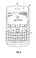
- Figure 3 illustrates a representation of a wireless device that includes the keypad assembly as a portion thereof.
- Figure 4 illustrates a representation of the keypad assembly shown in Figures 1-2 in a convex carrier configuration upon a cylindrical fixture.
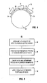
- Figure 5 illustrates a method flow diagram representative of the method of operation of an implementation of the present disclosure.
- the present disclosure accordingly, advantageously provides an apparatus, and an associated method, for a keypad assembly that includes a finish, such as a decoration or a painting, that is applied, e.g., to interstitial portions of keys of the keypad assembly.
- a finish such as a decoration or a painting
- a manner is provided by which to provide keys of a keypad with painting, decoration, or other finish at desired portions of the keys, including interstitial portions of the keys.
- a keypad having a painting, decoration, or other finish applied to interstitial portions of the keys of the keypad is also provided.
- a keypad of small dimensions having keys positioned close to one another, is able to be decorated or painted in a desired manner including a finish applied to an interstitial portion of a key of a keypad, if desired.
- a keypad in another aspect of the present disclosure, includes a plurality of keys that are arranged in a manner that defines an array of keys, i.e., a keypad array.
- the keypad array comprises, for instance, a numeric keypad array or, e.g., a QWERTY keypad array.
- membrane pieces of a membrane are positioned between undersurfaces of the keys of the keypad array positioned, e.g., between adjacent keys of the keypad array.
- a carrier membrane is provided.
- the carrier membrane is formed of a flexible material, such as a flexible thermoplastic material and is of dimensions to carry the keys that are arranged in the keypad array and also the key membrane pieces thereon.
- the keys and the key membrane pieces are, e.g., affixed in position upon the carrier membrane or are formed integral therewith.
- the carrier membrane is permitting of a bending flex motion to permit flexing of the carrier membrane between a horizontal, substantially planar position, and a convex configuration, i.e., a convex carrier configuration, in which the keys of the keypad array and the key membrane pieces are flexed together with the carrier membrane such that the keys and the key member pieces exhibit increased angular offsets relative to one another.
- a finish such as painting or a decoration, is applied to selected portions of the keys of the keypad array.
- the finish is applied to any desired portion of a key of the keypad array that is visible to a user of an electronic device to which the keypad assembly is associated.
- the desired finish is applied to the keys of the keypad array at the desired portions of the keys of the array, including at interstitial portions of the keys, irrespective of the spacing between the adjacent keys of the key pad array when the carrier membrane, upon which the keypad array is carried, is in a substantially planar, or flat, position.
- the carrier membrane, with the keypad array and key membrane pieces carried thereon is positioned in the convex carrier configuration by wrapping the carrier membrane about a cylindrical fixture.
- the cylindrical fixture comprises, for instance, a spindle or other convex-surfaced piece capable of supporting or providing for positioning of the carrier membrane thereon.
- the carrier membrane, and the keys and key membrane pieces carried thereon are removed from the cylindrical fixture, and the key pad assembly is assembled to form part of the wireless, or other electronic, device pursuant to an assembly process.
- a keypad assembly is therefore provided that is permitted to be of small physical dimensions while also permitting a finish to be applied upon a desired portion of one or more keys of the key pad assembly including at an interstitial portion of a key of the keypad array.
- a keypad assembly and an associated method, is provided.
- a plurality of keys are arranged a keypad array.
- a group of key membrane pieces are provided.
- a key membrane piece of the group is positioned between under surfaces of adjacent keys of the keypad array into which the plurality of keys is arranged.
- a carrier membrane is configured to carry the plurality of keys and the group of key membrane pieces thereon. The carrier membrane is permitting of a bending flex motion to position the carrier membrane into a convex carrier configuration at which the keys and the key member pieces exhibit increased angular offsets relative to one another.
- a keypad assembly 10 constructed pursuant to an implementation of the present disclosure provides for input of information, control commands, and instructions to an electronic device (not shown in Figure 1 ).
- the keypad assembly includes a plurality of keys 14 that are arranged in rows and columns to form an array of keys, i.e., a keypad array.
- the keys define a QWERTY keypad with alphabetical characters arranged in QWERTY style, of which individual ones of the keys are actuated by a user to enter a character associated with the individual key.
- the keys 14 are comprised of a thermoplastic material and are configured in the form of upstanding buttons that extend above a face surface of the keypad assembly. Individual ones of the keys are separated by separation distances 18.
- the separation distance 18 differs in the horizontal and vertical directions. That is to say, in one implementation, the separation distances between keys adjacent to one another in a vertical direction are different than the separation distances that separate keys adjacent to one another in a horizontal direction. And, in another implementation, separation distances between adjacent keys are row and/or column dependent.
- membrane pieces 22 are positioned to extend between under surface portions (hidden from view in Figure 1 ) that support the keys 14 in the arrayed configuration.
- the membrane pieces 22, in one implementation, are connected together and define a pattern, which, in turn, defines the array by controlling the positioning of the keys 14.
- the keypad assembly further includes a carrier membrane 24.
- the carrier membrane is positioned beneath the key membrane pieces 22 and the keys 14. Edge portions of the carrier membrane are illustrated in the Figure 1 . The edge portions extend beyond the key membrane pieces thereby to permit carriage of the key membrane pieces together with the keys when arranged in the array configuration.
- the carrier membrane is comprised of a flexible material that is permitting of a bending flex motion responsive to application of bending forces applied thereto,
- the key membrane pieces 22 and the keys 14, when carried upon the carrier membrane, as shown, are moved together with movement of the carrier membrane when the bending flex forces are applied to bend the carrier membrane into a convex carrier configuration.
- the bending of the carrier membrane into the convex carrier configuration causes the keys 14 carried upon the carrier membrane to be reoriented, to be repositioned relative to one another.
- the keys, and the key member pieces extending between undersurfaces of adjacent ones of the keys are caused to exhibit altered angular offsets relative to one another.
- the keypad 10 further includes a finish 26 applied portions of one or more of the keys 14.
- the finish comprises, for instance, painting applied to the key or decoration applied to the key.
- the finish 24 pursuant to an implementation of the present disclosure, is applied at any desired portion of the key that might be visible to a user of the keypad assembly during normal operation. Due to the small separation distances separating adjacent keys 14 of the keypad array, the application of the finish to interstitial portions of the adjacent keys is carried out by first applying the bending flex forces to the carrier member, and the key and key membrane pieces carried thereon to position the carrier membrane in the convex carrier configuration. Once positioned in the convex carrier configuration, the finish is applied, and the carrier membrane is permitted to return to a non-flexed position.
- the reorientation of the keys responsive to the bending movement of the carrier membrane into the altered angular offsets relative to one another opens areas of the keys or application of the finish that otherwise would not be accessible. Interstitial portions of the keys, for instance, which otherwise would not be accessible to apply the finish thereto are amenable for application of the finish when the carrier membrane is positioned in the convex carrier configuration.
- Figure 2 again illustrates the keypad assembly 10.
- the view shown in Figure 2 again illustrates the keys 14, the key membrane pieces 22 positioned between undersurfaces 28 of adjacent ones of the keys, and the carrier membrane 22.
- the keys 14 are shown to be seated at locations defined by the key membrane pieces 22, and the positioning of the keys 14 define the separation distances 18 that separate the adjacent ones of the keys 14.
- the carrier membrane 24 is again shown to carry the keys 14 and key membrane pieces 22 and also to be of dimensions to extend beyond the keypad array formed of the keys 14 positioned at the locations defined by the key membrane pieces 22.
- the arrows 34 represent bending flex forces that are applied to the carrier membrane to position the carrier membrane in the convex carrier configuration to alter the angular offsets of the keys 14 relative to one another.
- the keys 14 are upstanding and parallel to one another.
- the application of the bending flex forces to the carrier membrane causes flexing motion of the membrane to cause the keys to be reoriented to be offset from one another to make the interstitial portions of the keys amendable for application of a finish thereto.
- the carrier membrane once the desired finish is applied to the keys, is returned to the position, as shown in Figure 2 , upon termination of application of the forces 34 or, alternately, by application of forces reverse to those of arrows 34.
- FIG 3 illustrates a wireless device 42 that includes the keypad assembly 10 as a portion thereof.
- the keypad assembly 10 includes a finish applied to the keys 14 at any desired portions thereof visible to a viewer or user of the wireless device.
- the keypad assembly 10 is here supported at a housing 46 of the wireless device, positioned below, as shown, a display element 48.
- the display element 48 and the keyboard assembly together form the user interface of the wireless device.
- a user of the wireless device enters information, commands, and operational control instructions by way of the keypad assembly 10.
- the user actuates individual keys 14 of the keypad assembly to enter the information, commands, or instructions.
- circuitry housed within the housing 46 causes operation of the wireless device in conformity with the entered instructions or commands or causes communication of the entered information, as appropriate.
- Figure 4 again illustrates the keypad assembly 10, again illustrating the key 14, key membrane pieces 22, and carrier membrane 24.
- the keypad assembly is positioned at, or supported on, a cylindrical fixture 62.
- the carrier membrane is comprised of a flexible material, the membrane is positionable to be supported or otherwise positioned at the fixture.
- the keys and key membrane pieces are reoriented relative to one another to alter the relative angular offsets between the elements and to expose the interstitial portions of the keys and key membrane pieces for application of the finish material thereon.
- the keypad assembly is removed from the fixture 62, and the keypad assembly is available for assembly as part of an electronic device, such as the wireless device 42 shown in Figure 3 .
- the positioning of the keypad assembly at a cylindrical fixture, or the like, is readily carried out, such as by an automated process during assembly operations. Because the positioning of the carrier membrane in the convex carrier configuration positions even interstitial portions of the keys of the keypad assembly to permit application of a finish thereto, almost any desired finish, pattern, decoration, or painting is able to be applied to any portion of the keys or key membrane that are noticeable by a viewer positioned above the keypad assembly.
- Figure 5 illustrates a method 82 of an implementation of the present disclosure. The method facilitates formation of a keypad assembly.
- a plurality of keys are arranged to form a keypad array.
- key membrane pieces are positioned between undersurfaces of adjacent keys of the keypad array.
- the keypad array and the key membrane pieces are carried on a carrier membrane.
- the carrier membrane is permitting of a bending flex motion into a convex carrier configuration at which the keypad array and the key membrane pieces, carried on the carrier membrane, exhibit increased angular offsets relative to one another.
- a coating is applied to a desired portion of one or more keys of the keypad array.
- a manner is provided by which to apply a finish to any desired portion of a key of a keypad array.
- the manner is amendable for automated assembly operations in which the keypad assembly is created and a finish is applied thereto.
Landscapes
- Input From Keyboards Or The Like (AREA)
- Telephone Set Structure (AREA)
Claims (14)
- Ein Verfahren (82) zum Erleichtern einer Bildung einer Tastatur-Baugruppe (10), wobei das Verfahren aufweist:Anordnen (84) einer Vielzahl von Tasten (14), um eine Tastatur-Anordnung zu bilden;Positionieren (86) von Tasten-Membranstücken (22) zwischen Unterseiten von angrenzenden Tasten der Tastatur-Anordnung;Tragen (88) der Tastatur-Anordnung und Tasten-Membranstücke auf einer Trägermembran (24), wobei die Trägermembran eine Biege-Flex-Bewegung (34) in eine konvexe Träger-Konfiguration erlaubt, bei der die Tastatur-Anordnung und die Tasten-Membranstücke, die auf der Trägermembran getragen werden, größere Winkelversätze relativ zueinander zeigen;gekennzeichnet durchBiegen der Trägermembran und der darauf getragenen Tastatur-Anordnung und Tasten-Membranstücke in der Biege-Flex-Bewegung in die konvexe Träger-Konfiguration; undAnwenden (92) einer Oberflächenbehandlung (26) auf zumindest einen Zwischenteil einer Taste der Tastatur-Anordnung.
- Das Verfahren (82) gemäß Anspruch 1, wobei das Biegen der Trägermembran (24) ein Wickeln der Trägermembran um eine zylindrische Einrichtung (62) aufweist.
- Das Verfahren (82) gemäß Anspruch 1, wobei das Anwenden (92) der Oberflächenbehandlung (26) ein Aufbringen einer Beschichtung auf zumindest einen Zwischenteil einer Taste (14) der Tastatur-Anordnung aufweist.
- Das Verfahren (82) gemäß Anspruch 1, wobei das Anwenden (92) der Oberflächenbehandlung (26) ein Bemalen zumindest eines Zwischenteils einer Taste (14) der Tastatur-Anordnung aufweist.
- Das Verfahren (82) gemäß Anspruch 1, wobei die mögliche Biege-Flex-Bewegung (34) der Trägermembran (24) eine Bewegung aufweist zum Positionieren der Trägermembran in die konvexe Träger-Konfiguration, bei der Zwischenteile von Tasten (14) der Tastatur-Anordnung positioniert sind, die Anwendung der Oberflächenbehandlung zu erhalten.
- Das Verfahren (82) gemäß Anspruch 1, wobei das Positionieren (86) der Tasten-Membranstücke (22) zwischen den Unterseiten ein Positionieren der Tasten-Membranstücke an Licht-blockierenden Positionen aufweist.
- Eine Tastatur-Baugruppe (10), erlangt durch das Verfahren (82) gemäß Anspruch 1, die aufweist:eine Vielzahl von Tasten (14), die in einer Tastatur-Anordnung angeordnet sind;eine Gruppe von Tasten-Membranstücken (22), wobei ein Tasten-Membranstück der Gruppe zwischen Unterseiten von angrenzenden Tasten der Tastatur-Anordnung positioniert ist, in die die Vielzahl von Tasten angeordnet ist; undeine Trägermembran (24), die konfiguriert ist zum darauf Tragen der Vielzahl von Tasten und der Gruppe von Tasten-Membranstücken, wobei die Trägermembran eine Biege-Flex-Bewegung (34) in eine konvexe Träger-Konfiguration erlaubt, bei der die Tasten und die Tasten-Membranstücke veränderte Winkelversätze relativ zueinander zeigen,wobei eine Oberflächenbehandlung auf zumindest einen Zwischenteil einer Taste der Tastatur-Anordnung angewendet wird.
- Die Tastatur-Baugruppe (10) gemäß Anspruch 7, wobei die Oberflächenbehandlung eine Dekoration aufweist.
- Die Tastatur-Baugruppe (10) gemäß Anspruch 7, wobei die Oberflächenbehandlung Farbe aufweist.
- Die Tastatur-Baugruppe (10) gemäß Anspruch 7, wobei die Tasten-Membranstücke (22) aus der Gruppe von Tasten-Membranstücken die Biege-Flex-Bewegung (34) zusammen mit der Biege-Flex-Bewegung der Trägermembran (24) ermöglichen.
- Die Tastatur-Baugruppe (10) gemäß Anspruch 7, wobei die Tasten-Membranstücke (22) aus der Gruppe von Tasten-Membranstücken und die Trägermembran (34) integral ausgebildet sind.
- Die Tastatur-Baugruppe (10) gemäß Anspruch 11, wobei die Vielzahl von Tasten (14) weiter mit den Tasten-Membranstücken (22) der Gruppe von Tasten-Membranstücken und der Trägermembran (24) integral ausgebildet sind.
- Die Tastatur-Baugruppe (10) gemäß Anspruch 7, wobei die Biege-Flex-Bewegung (34), die mit der Trägermembran (24) möglich ist, eine Bewegung aufweist zum Positionieren der Trägermembran in die konvexe Träger-Konfiguration, bei der Zwischenteile der Tasten (14) der Vielzahl positioniert sind, eine Anwendung der Oberflächenbehandlung zu erhalten.
- Die Tastatur-Baugruppe (10) gemäß Anspruch 7, wobei die konvexe Träger-Konfiguration, in die die Trägermembran (24) positionierbar ist, eine in eine zylindrische Einrichtung setzbare Konfiguration (62) aufweist.
Priority Applications (2)
| Application Number | Priority Date | Filing Date | Title |
|---|---|---|---|
| EP20110159890 EP2503579B1 (de) | 2011-03-25 | 2011-03-25 | Vorrichtung und zugehöriges Verfahren zum Auftragen eines Abschlussprodukts auf eine Tastatur |
| CA 2769372 CA2769372A1 (en) | 2011-03-25 | 2012-02-24 | Apparatus, and associated method, for applying a finish to a keypad |
Applications Claiming Priority (1)
| Application Number | Priority Date | Filing Date | Title |
|---|---|---|---|
| EP20110159890 EP2503579B1 (de) | 2011-03-25 | 2011-03-25 | Vorrichtung und zugehöriges Verfahren zum Auftragen eines Abschlussprodukts auf eine Tastatur |
Publications (2)
| Publication Number | Publication Date |
|---|---|
| EP2503579A1 EP2503579A1 (de) | 2012-09-26 |
| EP2503579B1 true EP2503579B1 (de) | 2013-06-26 |
Family
ID=44280753
Family Applications (1)
| Application Number | Title | Priority Date | Filing Date |
|---|---|---|---|
| EP20110159890 Active EP2503579B1 (de) | 2011-03-25 | 2011-03-25 | Vorrichtung und zugehöriges Verfahren zum Auftragen eines Abschlussprodukts auf eine Tastatur |
Country Status (2)
| Country | Link |
|---|---|
| EP (1) | EP2503579B1 (de) |
| CA (1) | CA2769372A1 (de) |
Family Cites Families (2)
| Publication number | Priority date | Publication date | Assignee | Title |
|---|---|---|---|---|
| JPS60131209A (ja) * | 1983-12-20 | 1985-07-12 | Toray Silicone Co Ltd | 印刷成形物の製造方法 |
| DE102008053351B3 (de) * | 2008-10-27 | 2010-08-05 | Gigaset Communications Gmbh | Bedienfeld für ein Tastaturmodul, Tastaturmodul und Verfahren zu deren Herstellung |
-
2011
- 2011-03-25 EP EP20110159890 patent/EP2503579B1/de active Active
-
2012
- 2012-02-24 CA CA 2769372 patent/CA2769372A1/en not_active Abandoned
Also Published As
| Publication number | Publication date |
|---|---|
| EP2503579A1 (de) | 2012-09-26 |
| CA2769372A1 (en) | 2012-09-25 |
Similar Documents
| Publication | Publication Date | Title |
|---|---|---|
| US6660200B2 (en) | Manufacturing method for sheet shaped key top | |
| US6824321B2 (en) | Keypad assembly | |
| US20080309638A1 (en) | Input device and method of manufacturing module unit for input device | |
| US7999199B2 (en) | Electric commutator with multiple switch ways | |
| EP2819153A2 (de) | Verfahren zur Herstellung eines Fingerabdruckerkennungshausschlüssels mit versetzter Struktur des dekorativen Teils und Struktur eines Fingerabdruckerkennungshausschlüssels | |
| US8022324B2 (en) | Method of manufacturing a keypad structure having a transparent keycap and keypad structure having a transparent keycap | |
| US7489302B2 (en) | Handheld mobile communication device with flexible keys | |
| EP2503579B1 (de) | Vorrichtung und zugehöriges Verfahren zum Auftragen eines Abschlussprodukts auf eine Tastatur | |
| US8598476B2 (en) | Apparatus, and associated method, for applying a finish to a keypad | |
| US20090095611A1 (en) | Electrical switch with multiple switching channels | |
| KR20000059919A (ko) | 이동통신 단말기의 한글 자음/모음 입력방법 | |
| US20100245133A1 (en) | Key sheet | |
| EP1930924A1 (de) | Dünn-schlüsselblatt und prozess zu seiner herstellung | |
| EP2402968B1 (de) | Umlenksteg für eine Tastaturanordnung | |
| EP2302879B1 (de) | Schlüsselanordnung für eine elektronische Vorrichtung mit einer Mehrfachzeichen-Schlüsselkappe | |
| EP2518593B1 (de) | Tastatur mit einer gebogenen Form | |
| KR100538112B1 (ko) | 플라스틱 시트를 이용한 버튼 플레이트 및 개인휴대단말기 | |
| KR20100102865A (ko) | 전자기기 입력장치 및 그 제조방법 | |
| KR100844441B1 (ko) | 개인휴대단말기용 버튼 플레이트 | |
| AU9520098A (en) | Keypad having keys arranged in clock manner | |
| KR100678581B1 (ko) | 적층인쇄 키패드 및 그 제조방법 | |
| JP2002329437A (ja) | 押釦スイッチ用賦形フィルム、押釦スイッチ用カバー部材及びこれらの製造方法 | |
| EP2328164B1 (de) | Tastenanordnung für eine elektronische Vorrichtung mit einer verbundenen Tastenkappe | |
| EP2487880B1 (de) | Elektronisches Mobilgerät mit einer Tastaturanordnung mit Overlayfolie | |
| JP2002015639A (ja) | 押釦スイッチ用部材 |
Legal Events
| Date | Code | Title | Description |
|---|---|---|---|
| PUAI | Public reference made under article 153(3) epc to a published international application that has entered the european phase |
Free format text: ORIGINAL CODE: 0009012 |
|
| 17P | Request for examination filed |
Effective date: 20110325 |
|
| AK | Designated contracting states |
Kind code of ref document: A1 Designated state(s): AL AT BE BG CH CY CZ DE DK EE ES FI FR GB GR HR HU IE IS IT LI LT LU LV MC MK MT NL NO PL PT RO RS SE SI SK SM TR |
|
| AX | Request for extension of the european patent |
Extension state: BA ME |
|
| GRAP | Despatch of communication of intention to grant a patent |
Free format text: ORIGINAL CODE: EPIDOSNIGR1 |
|
| GRAS | Grant fee paid |
Free format text: ORIGINAL CODE: EPIDOSNIGR3 |
|
| GRAA | (expected) grant |
Free format text: ORIGINAL CODE: 0009210 |
|
| AK | Designated contracting states |
Kind code of ref document: B1 Designated state(s): AL AT BE BG CH CY CZ DE DK EE ES FI FR GB GR HR HU IE IS IT LI LT LU LV MC MK MT NL NO PL PT RO RS SE SI SK SM TR |
|
| REG | Reference to a national code |
Ref country code: GB Ref legal event code: FG4D |
|
| REG | Reference to a national code |
Ref country code: CH Ref legal event code: EP |
|
| REG | Reference to a national code |
Ref country code: AT Ref legal event code: REF Ref document number: 619022 Country of ref document: AT Kind code of ref document: T Effective date: 20130715 |
|
| REG | Reference to a national code |
Ref country code: IE Ref legal event code: FG4D |
|
| REG | Reference to a national code |
Ref country code: CH Ref legal event code: PFA Owner name: BLACKBERRY LIMITED, CA Free format text: FORMER OWNER: RESEARCH IN MOTION LIMITED, CA |
|
| REG | Reference to a national code |
Ref country code: DE Ref legal event code: R096 Ref document number: 602011002109 Country of ref document: DE Effective date: 20130829 |
|
| RAP2 | Party data changed (patent owner data changed or rights of a patent transferred) |
Owner name: BLACKBERRY LIMITED |
|
| REG | Reference to a national code |
Ref country code: NL Ref legal event code: TD Effective date: 20131002 |
|
| REG | Reference to a national code |
Ref country code: NL Ref legal event code: T3 |
|
| PG25 | Lapsed in a contracting state [announced via postgrant information from national office to epo] |
Ref country code: SI Free format text: LAPSE BECAUSE OF FAILURE TO SUBMIT A TRANSLATION OF THE DESCRIPTION OR TO PAY THE FEE WITHIN THE PRESCRIBED TIME-LIMIT Effective date: 20130626 Ref country code: GR Free format text: LAPSE BECAUSE OF FAILURE TO SUBMIT A TRANSLATION OF THE DESCRIPTION OR TO PAY THE FEE WITHIN THE PRESCRIBED TIME-LIMIT Effective date: 20130927 Ref country code: NO Free format text: LAPSE BECAUSE OF FAILURE TO SUBMIT A TRANSLATION OF THE DESCRIPTION OR TO PAY THE FEE WITHIN THE PRESCRIBED TIME-LIMIT Effective date: 20130926 Ref country code: SE Free format text: LAPSE BECAUSE OF FAILURE TO SUBMIT A TRANSLATION OF THE DESCRIPTION OR TO PAY THE FEE WITHIN THE PRESCRIBED TIME-LIMIT Effective date: 20130626 Ref country code: FI Free format text: LAPSE BECAUSE OF FAILURE TO SUBMIT A TRANSLATION OF THE DESCRIPTION OR TO PAY THE FEE WITHIN THE PRESCRIBED TIME-LIMIT Effective date: 20130626 Ref country code: LT Free format text: LAPSE BECAUSE OF FAILURE TO SUBMIT A TRANSLATION OF THE DESCRIPTION OR TO PAY THE FEE WITHIN THE PRESCRIBED TIME-LIMIT Effective date: 20130626 |
|
| REG | Reference to a national code |
Ref country code: CH Ref legal event code: PCOW Free format text: NEW ADDRESS: 2200 UNIVERSITY AVENUE EAST, WATERLOO, ON N2K 0A7 (CA) Ref country code: AT Ref legal event code: MK05 Ref document number: 619022 Country of ref document: AT Kind code of ref document: T Effective date: 20130626 |
|
| REG | Reference to a national code |
Ref country code: LT Ref legal event code: MG4D |
|
| RAP2 | Party data changed (patent owner data changed or rights of a patent transferred) |
Owner name: BLACKBERRY LIMITED |
|
| PG25 | Lapsed in a contracting state [announced via postgrant information from national office to epo] |
Ref country code: BG Free format text: LAPSE BECAUSE OF FAILURE TO SUBMIT A TRANSLATION OF THE DESCRIPTION OR TO PAY THE FEE WITHIN THE PRESCRIBED TIME-LIMIT Effective date: 20130926 Ref country code: RS Free format text: LAPSE BECAUSE OF FAILURE TO SUBMIT A TRANSLATION OF THE DESCRIPTION OR TO PAY THE FEE WITHIN THE PRESCRIBED TIME-LIMIT Effective date: 20130626 Ref country code: HR Free format text: LAPSE BECAUSE OF FAILURE TO SUBMIT A TRANSLATION OF THE DESCRIPTION OR TO PAY THE FEE WITHIN THE PRESCRIBED TIME-LIMIT Effective date: 20130626 |
|
| PG25 | Lapsed in a contracting state [announced via postgrant information from national office to epo] |
Ref country code: LV Free format text: LAPSE BECAUSE OF FAILURE TO SUBMIT A TRANSLATION OF THE DESCRIPTION OR TO PAY THE FEE WITHIN THE PRESCRIBED TIME-LIMIT Effective date: 20130626 |
|
| PG25 | Lapsed in a contracting state [announced via postgrant information from national office to epo] |
Ref country code: SK Free format text: LAPSE BECAUSE OF FAILURE TO SUBMIT A TRANSLATION OF THE DESCRIPTION OR TO PAY THE FEE WITHIN THE PRESCRIBED TIME-LIMIT Effective date: 20130626 Ref country code: IS Free format text: LAPSE BECAUSE OF FAILURE TO SUBMIT A TRANSLATION OF THE DESCRIPTION OR TO PAY THE FEE WITHIN THE PRESCRIBED TIME-LIMIT Effective date: 20131026 Ref country code: PT Free format text: LAPSE BECAUSE OF FAILURE TO SUBMIT A TRANSLATION OF THE DESCRIPTION OR TO PAY THE FEE WITHIN THE PRESCRIBED TIME-LIMIT Effective date: 20131028 Ref country code: EE Free format text: LAPSE BECAUSE OF FAILURE TO SUBMIT A TRANSLATION OF THE DESCRIPTION OR TO PAY THE FEE WITHIN THE PRESCRIBED TIME-LIMIT Effective date: 20130626 Ref country code: CY Free format text: LAPSE BECAUSE OF FAILURE TO SUBMIT A TRANSLATION OF THE DESCRIPTION OR TO PAY THE FEE WITHIN THE PRESCRIBED TIME-LIMIT Effective date: 20130911 Ref country code: CZ Free format text: LAPSE BECAUSE OF FAILURE TO SUBMIT A TRANSLATION OF THE DESCRIPTION OR TO PAY THE FEE WITHIN THE PRESCRIBED TIME-LIMIT Effective date: 20130626 Ref country code: AT Free format text: LAPSE BECAUSE OF FAILURE TO SUBMIT A TRANSLATION OF THE DESCRIPTION OR TO PAY THE FEE WITHIN THE PRESCRIBED TIME-LIMIT Effective date: 20130626 Ref country code: BE Free format text: LAPSE BECAUSE OF FAILURE TO SUBMIT A TRANSLATION OF THE DESCRIPTION OR TO PAY THE FEE WITHIN THE PRESCRIBED TIME-LIMIT Effective date: 20130626 |
|
| PG25 | Lapsed in a contracting state [announced via postgrant information from national office to epo] |
Ref country code: PL Free format text: LAPSE BECAUSE OF FAILURE TO SUBMIT A TRANSLATION OF THE DESCRIPTION OR TO PAY THE FEE WITHIN THE PRESCRIBED TIME-LIMIT Effective date: 20130626 Ref country code: ES Free format text: LAPSE BECAUSE OF FAILURE TO SUBMIT A TRANSLATION OF THE DESCRIPTION OR TO PAY THE FEE WITHIN THE PRESCRIBED TIME-LIMIT Effective date: 20131007 Ref country code: RO Free format text: LAPSE BECAUSE OF FAILURE TO SUBMIT A TRANSLATION OF THE DESCRIPTION OR TO PAY THE FEE WITHIN THE PRESCRIBED TIME-LIMIT Effective date: 20130626 |
|
| PG25 | Lapsed in a contracting state [announced via postgrant information from national office to epo] |
Ref country code: CY Free format text: LAPSE BECAUSE OF FAILURE TO SUBMIT A TRANSLATION OF THE DESCRIPTION OR TO PAY THE FEE WITHIN THE PRESCRIBED TIME-LIMIT Effective date: 20130626 |
|
| PG25 | Lapsed in a contracting state [announced via postgrant information from national office to epo] |
Ref country code: DK Free format text: LAPSE BECAUSE OF FAILURE TO SUBMIT A TRANSLATION OF THE DESCRIPTION OR TO PAY THE FEE WITHIN THE PRESCRIBED TIME-LIMIT Effective date: 20130626 |
|
| PLBE | No opposition filed within time limit |
Free format text: ORIGINAL CODE: 0009261 |
|
| STAA | Information on the status of an ep patent application or granted ep patent |
Free format text: STATUS: NO OPPOSITION FILED WITHIN TIME LIMIT |
|
| PG25 | Lapsed in a contracting state [announced via postgrant information from national office to epo] |
Ref country code: IT Free format text: LAPSE BECAUSE OF FAILURE TO SUBMIT A TRANSLATION OF THE DESCRIPTION OR TO PAY THE FEE WITHIN THE PRESCRIBED TIME-LIMIT Effective date: 20130626 |
|
| 26N | No opposition filed |
Effective date: 20140327 |
|
| REG | Reference to a national code |
Ref country code: DE Ref legal event code: R097 Ref document number: 602011002109 Country of ref document: DE Effective date: 20140327 |
|
| REG | Reference to a national code |
Ref country code: DE Ref legal event code: R082 Ref document number: 602011002109 Country of ref document: DE Representative=s name: MERH-IP MATIAS ERNY REICHL HOFFMANN, DE |
|
| PG25 | Lapsed in a contracting state [announced via postgrant information from national office to epo] |
Ref country code: LU Free format text: LAPSE BECAUSE OF FAILURE TO SUBMIT A TRANSLATION OF THE DESCRIPTION OR TO PAY THE FEE WITHIN THE PRESCRIBED TIME-LIMIT Effective date: 20140325 |
|
| REG | Reference to a national code |
Ref country code: CH Ref legal event code: PL |
|
| REG | Reference to a national code |
Ref country code: DE Ref legal event code: R082 Ref document number: 602011002109 Country of ref document: DE Representative=s name: MERH-IP MATIAS ERNY REICHL HOFFMANN, DE Effective date: 20140925 Ref country code: DE Ref legal event code: R081 Ref document number: 602011002109 Country of ref document: DE Owner name: BLACKBERRY LIMITED, WATERLOO, CA Free format text: FORMER OWNER: RESEARCH IN MOTION LTD., WATERLOO, ONTARIO, CA Effective date: 20140925 Ref country code: DE Ref legal event code: R082 Ref document number: 602011002109 Country of ref document: DE Representative=s name: MERH-IP MATIAS ERNY REICHL HOFFMANN PATENTANWA, DE Effective date: 20140925 |
|
| REG | Reference to a national code |
Ref country code: IE Ref legal event code: MM4A |
|
| PG25 | Lapsed in a contracting state [announced via postgrant information from national office to epo] |
Ref country code: CH Free format text: LAPSE BECAUSE OF NON-PAYMENT OF DUE FEES Effective date: 20140331 Ref country code: LI Free format text: LAPSE BECAUSE OF NON-PAYMENT OF DUE FEES Effective date: 20140331 Ref country code: IE Free format text: LAPSE BECAUSE OF NON-PAYMENT OF DUE FEES Effective date: 20140325 |
|
| PG25 | Lapsed in a contracting state [announced via postgrant information from national office to epo] |
Ref country code: MT Free format text: LAPSE BECAUSE OF FAILURE TO SUBMIT A TRANSLATION OF THE DESCRIPTION OR TO PAY THE FEE WITHIN THE PRESCRIBED TIME-LIMIT Effective date: 20130626 |
|
| REG | Reference to a national code |
Ref country code: FR Ref legal event code: PLFP Year of fee payment: 6 |
|
| PG25 | Lapsed in a contracting state [announced via postgrant information from national office to epo] |
Ref country code: SM Free format text: LAPSE BECAUSE OF FAILURE TO SUBMIT A TRANSLATION OF THE DESCRIPTION OR TO PAY THE FEE WITHIN THE PRESCRIBED TIME-LIMIT Effective date: 20130626 |
|
| PG25 | Lapsed in a contracting state [announced via postgrant information from national office to epo] |
Ref country code: MC Free format text: LAPSE BECAUSE OF FAILURE TO SUBMIT A TRANSLATION OF THE DESCRIPTION OR TO PAY THE FEE WITHIN THE PRESCRIBED TIME-LIMIT Effective date: 20130626 |
|
| PG25 | Lapsed in a contracting state [announced via postgrant information from national office to epo] |
Ref country code: HU Free format text: LAPSE BECAUSE OF FAILURE TO SUBMIT A TRANSLATION OF THE DESCRIPTION OR TO PAY THE FEE WITHIN THE PRESCRIBED TIME-LIMIT; INVALID AB INITIO Effective date: 20110325 Ref country code: TR Free format text: LAPSE BECAUSE OF FAILURE TO SUBMIT A TRANSLATION OF THE DESCRIPTION OR TO PAY THE FEE WITHIN THE PRESCRIBED TIME-LIMIT Effective date: 20130626 |
|
| REG | Reference to a national code |
Ref country code: FR Ref legal event code: PLFP Year of fee payment: 7 |
|
| REG | Reference to a national code |
Ref country code: FR Ref legal event code: PLFP Year of fee payment: 8 |
|
| PG25 | Lapsed in a contracting state [announced via postgrant information from national office to epo] |
Ref country code: MK Free format text: LAPSE BECAUSE OF FAILURE TO SUBMIT A TRANSLATION OF THE DESCRIPTION OR TO PAY THE FEE WITHIN THE PRESCRIBED TIME-LIMIT Effective date: 20130626 |
|
| PG25 | Lapsed in a contracting state [announced via postgrant information from national office to epo] |
Ref country code: AL Free format text: LAPSE BECAUSE OF FAILURE TO SUBMIT A TRANSLATION OF THE DESCRIPTION OR TO PAY THE FEE WITHIN THE PRESCRIBED TIME-LIMIT Effective date: 20130626 |
|
| REG | Reference to a national code |
Ref country code: DE Ref legal event code: R082 Ref document number: 602011002109 Country of ref document: DE Ref country code: DE Ref legal event code: R081 Ref document number: 602011002109 Country of ref document: DE Owner name: MALIKIE INNOVATIONS LTD., IE Free format text: FORMER OWNER: BLACKBERRY LIMITED, WATERLOO, ONTARIO, CA |
|
| PGFP | Annual fee paid to national office [announced via postgrant information from national office to epo] |
Ref country code: GB Payment date: 20260319 Year of fee payment: 16 |
|
| PGFP | Annual fee paid to national office [announced via postgrant information from national office to epo] |
Ref country code: DE Payment date: 20260320 Year of fee payment: 16 |
|
| PGFP | Annual fee paid to national office [announced via postgrant information from national office to epo] |
Ref country code: NL Payment date: 20260323 Year of fee payment: 16 |
|
| PGFP | Annual fee paid to national office [announced via postgrant information from national office to epo] |
Ref country code: FR Payment date: 20260323 Year of fee payment: 16 |