EP2503538A1 - Rückbeleuchtungsvorrichtung, Steuerverfahren dafür und Anzeigevorrichtung - Google Patents
Rückbeleuchtungsvorrichtung, Steuerverfahren dafür und Anzeigevorrichtung Download PDFInfo
- Publication number
- EP2503538A1 EP2503538A1 EP12160845A EP12160845A EP2503538A1 EP 2503538 A1 EP2503538 A1 EP 2503538A1 EP 12160845 A EP12160845 A EP 12160845A EP 12160845 A EP12160845 A EP 12160845A EP 2503538 A1 EP2503538 A1 EP 2503538A1
- Authority
- EP
- European Patent Office
- Prior art keywords
- light source
- source unit
- white light
- emitting elements
- light
- Prior art date
- Legal status (The legal status is an assumption and is not a legal conclusion. Google has not performed a legal analysis and makes no representation as to the accuracy of the status listed.)
- Withdrawn
Links
- 238000000034 method Methods 0.000 title claims description 8
- 238000005286 illumination Methods 0.000 claims abstract description 54
- 238000005192 partition Methods 0.000 claims abstract description 13
- 230000003213 activating effect Effects 0.000 claims 3
- 230000001419 dependent effect Effects 0.000 claims 2
- 238000010586 diagram Methods 0.000 description 8
- 239000004973 liquid crystal related substance Substances 0.000 description 6
- 239000003086 colorant Substances 0.000 description 5
- 230000000694 effects Effects 0.000 description 3
- 238000005516 engineering process Methods 0.000 description 3
- 239000000758 substrate Substances 0.000 description 3
- 238000012986 modification Methods 0.000 description 1
- 230000004048 modification Effects 0.000 description 1
- 238000000638 solvent extraction Methods 0.000 description 1
Images

Classifications
-
- G—PHYSICS
- G09—EDUCATION; CRYPTOGRAPHY; DISPLAY; ADVERTISING; SEALS
- G09G—ARRANGEMENTS OR CIRCUITS FOR CONTROL OF INDICATING DEVICES USING STATIC MEANS TO PRESENT VARIABLE INFORMATION
- G09G3/00—Control arrangements or circuits, of interest only in connection with visual indicators other than cathode-ray tubes
- G09G3/20—Control arrangements or circuits, of interest only in connection with visual indicators other than cathode-ray tubes for presentation of an assembly of a number of characters, e.g. a page, by composing the assembly by combination of individual elements arranged in a matrix no fixed position being assigned to or needed to be assigned to the individual characters or partial characters
- G09G3/34—Control arrangements or circuits, of interest only in connection with visual indicators other than cathode-ray tubes for presentation of an assembly of a number of characters, e.g. a page, by composing the assembly by combination of individual elements arranged in a matrix no fixed position being assigned to or needed to be assigned to the individual characters or partial characters by control of light from an independent source
- G09G3/3406—Control of illumination source
- G09G3/3413—Details of control of colour illumination sources
-
- G—PHYSICS
- G09—EDUCATION; CRYPTOGRAPHY; DISPLAY; ADVERTISING; SEALS
- G09G—ARRANGEMENTS OR CIRCUITS FOR CONTROL OF INDICATING DEVICES USING STATIC MEANS TO PRESENT VARIABLE INFORMATION
- G09G3/00—Control arrangements or circuits, of interest only in connection with visual indicators other than cathode-ray tubes
- G09G3/20—Control arrangements or circuits, of interest only in connection with visual indicators other than cathode-ray tubes for presentation of an assembly of a number of characters, e.g. a page, by composing the assembly by combination of individual elements arranged in a matrix no fixed position being assigned to or needed to be assigned to the individual characters or partial characters
- G09G3/34—Control arrangements or circuits, of interest only in connection with visual indicators other than cathode-ray tubes for presentation of an assembly of a number of characters, e.g. a page, by composing the assembly by combination of individual elements arranged in a matrix no fixed position being assigned to or needed to be assigned to the individual characters or partial characters by control of light from an independent source
- G09G3/3406—Control of illumination source
- G09G3/342—Control of illumination source using several illumination sources separately controlled corresponding to different display panel areas, e.g. along one dimension such as lines
-
- G—PHYSICS
- G09—EDUCATION; CRYPTOGRAPHY; DISPLAY; ADVERTISING; SEALS
- G09G—ARRANGEMENTS OR CIRCUITS FOR CONTROL OF INDICATING DEVICES USING STATIC MEANS TO PRESENT VARIABLE INFORMATION
- G09G2310/00—Command of the display device
- G09G2310/02—Addressing, scanning or driving the display screen or processing steps related thereto
- G09G2310/0237—Switching ON and OFF the backlight within one frame
-
- G—PHYSICS
- G09—EDUCATION; CRYPTOGRAPHY; DISPLAY; ADVERTISING; SEALS
- G09G—ARRANGEMENTS OR CIRCUITS FOR CONTROL OF INDICATING DEVICES USING STATIC MEANS TO PRESENT VARIABLE INFORMATION
- G09G2310/00—Command of the display device
- G09G2310/02—Addressing, scanning or driving the display screen or processing steps related thereto
- G09G2310/024—Scrolling of light from the illumination source over the display in combination with the scanning of the display screen
-
- G—PHYSICS
- G09—EDUCATION; CRYPTOGRAPHY; DISPLAY; ADVERTISING; SEALS
- G09G—ARRANGEMENTS OR CIRCUITS FOR CONTROL OF INDICATING DEVICES USING STATIC MEANS TO PRESENT VARIABLE INFORMATION
- G09G2320/00—Control of display operating conditions
- G09G2320/02—Improving the quality of display appearance
- G09G2320/0247—Flicker reduction other than flicker reduction circuits used for single beam cathode-ray tubes
-
- G—PHYSICS
- G09—EDUCATION; CRYPTOGRAPHY; DISPLAY; ADVERTISING; SEALS
- G09G—ARRANGEMENTS OR CIRCUITS FOR CONTROL OF INDICATING DEVICES USING STATIC MEANS TO PRESENT VARIABLE INFORMATION
- G09G2320/00—Control of display operating conditions
- G09G2320/06—Adjustment of display parameters
- G09G2320/0666—Adjustment of display parameters for control of colour parameters, e.g. colour temperature
-
- G—PHYSICS
- G09—EDUCATION; CRYPTOGRAPHY; DISPLAY; ADVERTISING; SEALS
- G09G—ARRANGEMENTS OR CIRCUITS FOR CONTROL OF INDICATING DEVICES USING STATIC MEANS TO PRESENT VARIABLE INFORMATION
- G09G2330/00—Aspects of power supply; Aspects of display protection and defect management
- G09G2330/02—Details of power systems and of start or stop of display operation
- G09G2330/021—Power management, e.g. power saving
-
- G—PHYSICS
- G09—EDUCATION; CRYPTOGRAPHY; DISPLAY; ADVERTISING; SEALS
- G09G—ARRANGEMENTS OR CIRCUITS FOR CONTROL OF INDICATING DEVICES USING STATIC MEANS TO PRESENT VARIABLE INFORMATION
- G09G2354/00—Aspects of interface with display user
Definitions
- the present invention relates to an illumination control technology for a backlight apparatus that uses light emitting elements that can display white light.
- liquid crystal display (LDC) apparatuses have been developed as a display apparatus having a high definition, broad color gamut, and low power consumption.
- White light LEDs or LEDs that can display white light by mixing RGB colors and the like are used as light emitting diodes (below, abbreviated "LED") in a light source unit for a backlight apparatus.
- LED light emitting diodes
- blurring occurs in the video image. This is caused by the slowness in the response speed of the liquid crystal molecules that are used in a liquid crystal panel.
- 2000-321551 proposes a method in which the power supply to the LEDs of a backlight apparatus is stopped for a period during which the liquid crystal panel is responding and a flickering scan is carried out.
- Japanese Patent Laid-Open No. 2008-145909 discloses a technology in which a black image or a grey image is inserted over the entire screen as an improved method.
- Japanese Patent Laid-Open No. 2007-133407 discloses a backlight display that uses a white light source and an RGB light source.
- the RGB light source is used in a low brightness state, and when the required value of the brightness is increased, the white light source is added to the RGB light source.
- the white light source that can individually provide white light illumination has a broader color gamut.
- the color gamut changes due to the displayed brightness because the light sources that emit light in a low brightness state or a high brightness state are different.
- a backlight apparatus of the present invention uses light emitting elements that can provide white light illumination, reduces the variation in the color gamut due to the displayed brightness and improves video viewing characteristics.
- the present invention in its first aspect provides a backlight apparatus as specified in claims 1 to 8.
- the present invention in its second aspect provides a backlight apparatus method as specified in claim 9.
- a backlight apparatus uses light emitting elements that can provide white light illumination, reduces the variation in the color gamut due to displayed brightness and improves the video viewing characteristics.
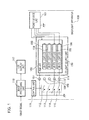
- FIG. 1 is a block diagram that shows an example of the configuration of a backlight apparatus 100 in order to explain, along with FIGS. 2A, 2B , and 3 , a first embodiment of the present invention.
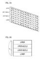
- FIG. 2A is a perspective view of the LED light source unit 150 that is shown in FIG. 1 .
- FIG. 2B is an explanatory diagram that shows the illumination sequence of the white light color LED units.
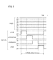
- FIG. 3 is a diagram that illustrates the illumination timing of each LED unit.
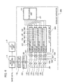
- FIG. 4 is a block diagram that shows an example of the configuration of the backlight apparatus 300 in order to explain, along with FIG. 5 , a second embodiment of the present invention.
- FIG. 5 is a diagram that illustrates the illumination timing of each LED unit.
- FIG. 1 is a block diagram that shows an example of a configuration of a backlight apparatus 100 according to a first embodiment of the present invention.
- the power source unit 101 supplies a power source voltage to each of the LEDs that is disposed in the LED light source unit 150.
- the LED light source unit 150 is an LED array substrate used in a backlight source.
- the first light source unit is provided with a plurality of white light LED light sources (white light LED units 103 to 106) that can individually provide white light illumination.
- the second light source unit is provided with an LED light source (below, referred to as the "RGB LED unit") 102 that obtains white light by mixing RGB primary color light.
- the first light source unit comprising light emitting elements that can provide white light illumination
- the second light source unit comprising light emitting elements having properties that differ from those of the light emitting elements of the first light source unit and that can provide white light illumination.
- FIG. 1 the first light source unit and the second light source unit are shown in a superimposed state.
- the RGB LED unit 102 is formed by a plurality of LEDs that each emit each of the RGB colors and emits white light over the entirety of the backlight by mixing colors.
- the first light source unit is formed by white light LED units 103 to 106, which use white light LEDs, and as shown in FIGS. 2A and B , these emit light in partition areas that are produced by segmenting the backlight source into four areas in the longitudinal direction of the backlight source.
- the white light LED units 103 to 106 respectively correspond to the upper portion, the upper middle portion, the lower middle portion, and the lower portion of the partition areas, which have been segmented from the top to the bottom of the screen, and illumination control is carried out in sequence as described below.
- the electric current sources 107 to 111 drive each of the LEDs by a constant electric power.
- the electric current source 107 is connected to the RGB LED unit 102, and the electric current sources 108 to 111 are respectively connected to the white light LED units 103 to 106.
- the electric current sources 108 to 111 are respectively grounded via the switching elements 112 to 115, and the electric current source 107 grounded without passing through a switching element.
- the control unit 116 that functions as an illumination control unit carries out timing control by which the LEDs of the backlight sources are caused to emit light according to a timing signal that is output by an image processing unit 118, and illuminates the white light LEDs 103 to 106 by turning ON the switching elements 112 to 115.
- the LCD display unit 117 is a liquid crystal display device that carries out the image display of graphics, characters, and images and the like according to image signals that are output by an image processing unit 118.
- FIG. 2A is a perspective view that shows an example of the configuration of the LED light source unit 150 that is shown in FIG. 1 .
- the LED light source unit 150 is a type of array substrate where LEDs are disposed on the backside of the display and arranged in parallel with respect to the direction of scanning line. Element groups, in which four LEDs form one group, are disposed in height and width on the substrate. Four LEDs, for example, a white light LED, a red light LED, a blue light LED, and a green light LED, are arranged as one group.
- the white light LEDs provided in each of the partition areas are each formed by the white light LED units 103 to 106 shown in FIG. 1 .
- red light LEDs, blue light LEDs, and green light LEDs can provide white light illumination by color mixing, and these form the RGB LED unit 102 shown in FIG. 1 .
- RGB LED unit 102 the light emission efficiency is low in comparison to white light illumination using white light LEDs, but a broad color gamut display is possible.
- light emission control of the white light LED units 103 to 106 is carried out by partitioning the entire screen into four areas in a vertical direction.
- the partition positions and the number of LEDs differ according to the size and performance of the display area.
- the configuration is not one in which four LEDs, consisting of the three RGB primary colors and white light, are arrayed as one group, if the whole screen can be illuminated by LEDs that can provide white light illuminated by color mixing and each of the white light LED units can be independently driven, any arrangement may be used. In this case, each of the LEDs that form the RGB LED unit 102 can be controlled in the same way regardless of their position on the screen.
- FIG. 2B shows the sequence in which illumination control is performed on white light LED units arrayed in the LED light source unit 150.
- the LCD display unit 117 is line-sequentially driven, and the display response is completed in a sequence starting from the top portion of the screen.
- the white light LED unit 103 is a light source unit corresponding to the upper area of the screen
- the white light LED unit 104 is a light source unit corresponding to the upper middle area
- the white light LED unit 105 is a light source unit corresponding to the lower middle area
- the white light LED unit 106 is a light source unit corresponding to the lower area.
- illumination control is carried out on the LED unit that is partitioned into four areas in a sequence from the upper area, to the upper middle area, to the lower middle area, and to the lower area of the screen in conformity with the display screen of the LCD display unit 117.
- illumination control returns again to the upper area and the illumination cycle is repeated.
- Illumination control may be carried out in a sequence from the lower area to the upper area.
- FIG. 3 is a diagram that illustrates the illumination timing of the LED units.
- “R”, “G”, “B” show the illumination state of each of the LEDs that form the RGB LED unit 102.
- the upper, upper middle, lower middle, and lower shown next to “W” show the illumination state of the white light LEDs respectively corresponding to the upper area, the upper middle area, the lower middle area, and the lower area of the screen.
- “ON” represents the illuminated state of an LED
- "OFF” represents the extinguished state of an LED.
- the time during which an image for one frame can be displayed corresponds to a time of about 16.7 ms (milliseconds).
- the RGB LED unit 102 is in a continuously illuminated state, and the white light LED units 103 to 106 are scan illuminated in sequence. Specifically, after the writing of the image signal, the operation of illuminating only the white light LEDs for each partition display area is executed in sequence within a one-frame period. In each frame, first, the white light LED unit 103 is illuminated, and at the point in time it is extinguished, the next white light LED unit 104 is illuminated. Subsequently, at the point in time that the white light LED unit 104 is extinguished, the next white light LED unit 105 is illuminated. After the white light LED unit 105 is extinguished and the white light LED unit 106 is illuminated at the end of the frame, the LED unit is extinguished at the end of the frame period, and the operation moves to the next frame.
- the RBG LED unit 102 is continuously illuminated at an amount of light equivalent to 100 cd/m 2 .
- the total amount of light emitted including that of the LED unit 102 is 200 cd/m 2 .
- the scan illumination is repeatedly executed using the pattern that is shown in FIG. 3 , and a brightness difference is produced between the portion at which white light illumination is carried out by color mixing by the RGB LED unit 102 and the white light LED units that are illuminated in sequence. Because the portion having the high brightness of 200 cd/m 2 is scan illuminated using the pattern that is shown in FIG. 3 , to an observer, the portion having a low brightness of 100 cd/m 2 appears relatively gray. That is, because the portion having the low brightness appears gray, the contrast difference between this portion and the portion having a high brightness becomes small, and flicker becomes unnoticeable.
- a display having a broad color gamut is possible because the RGB LED unit 102, which produces white light by color mixing, is caused to emit light to the entire backlight apparatus and the white light LED units 103 to 106 are caused to emit light by being scanned in sequence in the vertical direction of the screen at the partition areas.
- the effects that the flicker becomes unnoticeable and video viewing characteristics of the display apparatus are improved are obtained.
- LED element groups are used that can display white light by using RGB color mixing, but this is not limiting.
- a configuration may be used in which two or more types of light emitting element groups that can provide white light display by RGB color mixing are used, where the properties of the color gamut and power consumption and the like for the white light emission in the case of color mixing differ.
- a configuration may be used in which two or more types of white light emitting elements are used that can provide white light illumination individually, where the properties of the color gamut and power consumption during white light emission differ.
- the present invention can also be applied to the case in which a configuration is used for which the color gamut and power consumption and the like during white light emission differ due to using light emitting elements (groups) that are continuously illuminated and light emitting elements (groups) that are scan illuminated.
- FIG. 4 is a block diagram that shows an example of the configuration of a backlight apparatus 300 according to the second embodiment.
- the difference between the second embodiment and the first embodiment is that the illumination control of LEDs disposed in the LED light source unit 350 can be switched by the mode switching unit 351.
- the mode switching unit 351 the mode switching unit 351.
- the RGB LED unit 360 and white light LED unit 103 correspond to the upper area of the screen and the RGB LED unit 361 and the white light LED unit 104 correspond to the upper middle area of the screen.
- the RGB LED unit 362 and the white light LED unit 105 correspond to the lower middle area of the screen, and the RGB LED unit 363 and the white light LED unit 106 correspond to the lower area of the screen.
- the electric current sources 108 to 111 that drive the white light LED units 103 to 106 with a constant power are respectively grounded via switching elements 112 to 115.
- the electric current sources 365 to 368 that drive the RGB LED units 360 to 363 by a constant power are respectively grounded via the switching elements 370 to 373.
- the control unit 116 controls the timing at which the LEDs, which are the backlight sources, are caused to emit light according to a timing signal that is output by an image processing unit 118.
- the white light LED units 103 to 106 are respectively illuminated by the ON control of the switching elements 112 to 115, and the RGB LED units 360 to 363 are respectively illuminated by the ON control of the switching elements 370 to 373.
- the illumination control method for the LEDs that are disposed in the LED light source unit 350 is identical to the case of the first embodiment, but differs on the point that either of the white light LED units or the RGB LED units can be scan illuminated.
- the following illumination control can be selected by the mode switching unit 351:
- the mode switching unit 351 can select the illumination control mode according to the mode that has been selected by a user.
- the mode switching unit 351 may select the illumination control mode depending on the image that is displayed by the LCD display unit 117.
- the control unit 116 obtains information related to the image that is displayed on the LCD display unit 117 from the image processing unit 118, and transmits this information to the mode switching unit 351.
- the control unit 116 can obtain color gamut information and pixel number information for the image from metadata and the like that is appended to the image.
- the mode switching unit 351 selects an illumination control mode depending on the information that has been obtained.
- the broad color gamut mode is selected in the case in which the color gamut of the image that is displayed on the LCD display unit 117 is comparatively broader than a predetermined range, for example, in the case of an Adobe RGB (trademark) color gamut or a DCI (Digital Cinema Initiatives) rated color gamut.
- the low power consumption mode may be selected in the case in which the color gamut of the displayed image is comparatively narrow, for example, in the case of an sRGB color gamut.
- the mode switching unit 351 selects the broad color gamut mode in the case in which the pixel number of the image is comparatively larger than a predetermined value (threshold value) (for example, 1920x1080 pixels and the like).
- the low power consumption mode may be selected.
- a predetermined value for example, 640x480 pixels and the like.
- FIG. 5 shows the illumination timing of the LED units in the case in which control is carried out in the low power consumption mode.
- "W LED” in the figure indicates the illumination state of the white light LED units 103 to 106, and these respectively correspond to the light source units of the upper area, the upper middle area, the lower middle area, and the lower area of the screen.
- the white light LED units are all in an ON state ("ON") and continuously illuminated.
- the RGB LED units 360 to 363 respectively correspond to light source units for the upper area, the upper middle area, the lower middle area, and the lower area of the screen.
- These light source units perform scan illumination from the upper portion to the lower portion of the screen in conformity with the LCD display unit 117. That is, after the image signal has been written, the operation to illuminate only the RGB LED units that correspond to each of the partition areas is executed in sequence within 1 frame period.
- the power consumption in the illuminated state for the light source units of the RGB LED units is larger than that of the white light LED units.
- the power consumption can be restrained compared to the broad color gamut mode described in the first embodiment, because the illumination time of the white light LED units is long while the illumination time of the RGB LED units is short.
- the white light LED units 103 to 106 are continuously illuminated at an amount of light equivalent to 100 cd/m 2 .
- the total amount of light of the RGB LED units 360 to 363, when they are illuminated, and that of the white light LED units 103 to 106 is 200 cd/m 2 .
- a difference in brightness occurs between the portion at which only the white light LED units are illuminated and the portion at which the RGB LED units are illuminated in sequence.
- the portion having the high brightness of 200 cd/m 2 is scan illuminated using the pattern that is shown in FIG. 5 , and to an observer, the portion having the low brightness of 100 cd/m 2 appears relatively gray. That is, due to the portion having the low brightness appearing gray, the contrast difference between the portion having a low brightness and the portion having the high brightness becomes small, and flicker becomes unnoticeable.
- the second embodiment among the RGB LED units and the white light LED units, one is continuously illuminated and the other is scan illuminated. Thereby, illumination control for a broad color gamut mode and illumination control for a low power consumption mode can be selected. In either mode, the effects that the flicker becomes unnoticeable and the video viewing characteristics of the display apparatus are improved are obtained. In addition, an energy saving effect can be obtained by switching to the low power consumption mode.
Landscapes
- Engineering & Computer Science (AREA)
- Physics & Mathematics (AREA)
- Computer Hardware Design (AREA)
- General Physics & Mathematics (AREA)
- Theoretical Computer Science (AREA)
- Liquid Crystal (AREA)
- Liquid Crystal Display Device Control (AREA)
- Control Of Indicators Other Than Cathode Ray Tubes (AREA)
- Circuit Arrangement For Electric Light Sources In General (AREA)
- Planar Illumination Modules (AREA)
Applications Claiming Priority (2)
| Application Number | Priority Date | Filing Date | Title |
|---|---|---|---|
| JP2011062650 | 2011-03-22 | ||
| JP2011271220A JP5318184B2 (ja) | 2011-03-22 | 2011-12-12 | 発光装置およびその制御方法、並びに表示装置およびその制御方法 |
Publications (1)
| Publication Number | Publication Date |
|---|---|
| EP2503538A1 true EP2503538A1 (de) | 2012-09-26 |
Family
ID=46025323
Family Applications (1)
| Application Number | Title | Priority Date | Filing Date |
|---|---|---|---|
| EP12160845A Withdrawn EP2503538A1 (de) | 2011-03-22 | 2012-03-22 | Rückbeleuchtungsvorrichtung, Steuerverfahren dafür und Anzeigevorrichtung |
Country Status (4)
| Country | Link |
|---|---|
| US (1) | US9311862B2 (de) |
| EP (1) | EP2503538A1 (de) |
| JP (1) | JP5318184B2 (de) |
| CN (1) | CN102695331A (de) |
Families Citing this family (8)
| Publication number | Priority date | Publication date | Assignee | Title |
|---|---|---|---|---|
| JP5624011B2 (ja) * | 2011-11-18 | 2014-11-12 | 株式会社日本自動車部品総合研究所 | 情報提示装置 |
| KR101888682B1 (ko) | 2012-06-13 | 2018-08-16 | 삼성전자 주식회사 | 디스플레이장치 및 그 제어방법 |
| US9257095B2 (en) * | 2014-06-30 | 2016-02-09 | Sharp Kabushiki Kaisha | Display device with a backlight |
| CN104751802B (zh) * | 2015-04-20 | 2017-12-08 | 广东威创视讯科技股份有限公司 | Led显示屏扫描方法、led显示屏控制装置及系统 |
| EP3340219A4 (de) * | 2015-08-20 | 2019-04-24 | Mitsubishi Electric Corporation | Led-anzeigevorrichtung und ansteuerungsvorrichtung |
| DE102017115658A1 (de) * | 2017-07-12 | 2019-01-17 | Carl Zeiss Microscopy Gmbh | Flackern bei Winkel-variabler Beleuchtung |
| CN107749277B (zh) * | 2017-10-16 | 2022-05-17 | 维沃移动通信有限公司 | 一种屏幕亮度的控制方法、装置及移动终端 |
| JP2019191425A (ja) * | 2018-04-26 | 2019-10-31 | シャープ株式会社 | 制御装置、プログラム、電子機器および制御方法 |
Citations (6)
| Publication number | Priority date | Publication date | Assignee | Title |
|---|---|---|---|---|
| JP2000321551A (ja) | 1999-05-13 | 2000-11-24 | Sharp Corp | 液晶表示装置 |
| US20040264212A1 (en) * | 2003-06-30 | 2004-12-30 | Lg.Philips Lcd Co., Ltd. | Liquid crystal display module and driving apparatus thereof |
| US20060007112A1 (en) * | 2004-06-29 | 2006-01-12 | Lg Philips Lcd Co., Ltd. | Backlight unit of liquid crystal display device and method for driving the same |
| JP2007133407A (ja) | 2005-11-10 | 2007-05-31 | Avago Technologies Ecbu Ip (Singapore) Pte Ltd | 動的に最適化される光源を用いるバックライト型ディスプレイを構成するためのシステム及び方法 |
| JP2008145909A (ja) | 2006-12-13 | 2008-06-26 | Mitsubishi Electric Corp | 液晶表示装置 |
| WO2010062647A2 (en) * | 2008-10-28 | 2010-06-03 | Pixtronix, Inc. | System and method for selecting display modes |
Family Cites Families (7)
| Publication number | Priority date | Publication date | Assignee | Title |
|---|---|---|---|---|
| JP3523170B2 (ja) * | 2000-09-21 | 2004-04-26 | 株式会社東芝 | 表示装置 |
| EP1606788A1 (de) | 2003-03-17 | 2005-12-21 | Koninklijke Philips Electronics N.V. | Aktives matrixanzeigegerät mit abtastender rückbeleuchtung |
| JP2007264659A (ja) * | 2005-05-11 | 2007-10-11 | Sony Corp | 液晶表示装置及び電子機器 |
| JP5058631B2 (ja) * | 2006-03-03 | 2012-10-24 | 日本電気株式会社 | 光源装置、表示装置、端末装置及びそれらの制御方法 |
| WO2007132364A1 (en) * | 2006-05-09 | 2007-11-22 | Koninklijke Philips Electronics N.V. | Display device with a backlight |
| WO2008050506A1 (en) * | 2006-10-27 | 2008-05-02 | Sharp Kabushiki Kaisha | Liquid crystal display apparatus |
| JP5642347B2 (ja) | 2008-03-07 | 2014-12-17 | ミツミ電機株式会社 | 液晶バックライト装置 |
-
2011
- 2011-12-12 JP JP2011271220A patent/JP5318184B2/ja not_active Expired - Fee Related
-
2012
- 2012-03-15 US US13/421,335 patent/US9311862B2/en not_active Expired - Fee Related
- 2012-03-22 CN CN2012100841900A patent/CN102695331A/zh active Pending
- 2012-03-22 EP EP12160845A patent/EP2503538A1/de not_active Withdrawn
Patent Citations (6)
| Publication number | Priority date | Publication date | Assignee | Title |
|---|---|---|---|---|
| JP2000321551A (ja) | 1999-05-13 | 2000-11-24 | Sharp Corp | 液晶表示装置 |
| US20040264212A1 (en) * | 2003-06-30 | 2004-12-30 | Lg.Philips Lcd Co., Ltd. | Liquid crystal display module and driving apparatus thereof |
| US20060007112A1 (en) * | 2004-06-29 | 2006-01-12 | Lg Philips Lcd Co., Ltd. | Backlight unit of liquid crystal display device and method for driving the same |
| JP2007133407A (ja) | 2005-11-10 | 2007-05-31 | Avago Technologies Ecbu Ip (Singapore) Pte Ltd | 動的に最適化される光源を用いるバックライト型ディスプレイを構成するためのシステム及び方法 |
| JP2008145909A (ja) | 2006-12-13 | 2008-06-26 | Mitsubishi Electric Corp | 液晶表示装置 |
| WO2010062647A2 (en) * | 2008-10-28 | 2010-06-03 | Pixtronix, Inc. | System and method for selecting display modes |
Also Published As
| Publication number | Publication date |
|---|---|
| US9311862B2 (en) | 2016-04-12 |
| CN102695331A (zh) | 2012-09-26 |
| US20120242564A1 (en) | 2012-09-27 |
| JP2012212100A (ja) | 2012-11-01 |
| JP5318184B2 (ja) | 2013-10-16 |
Similar Documents
| Publication | Publication Date | Title |
|---|---|---|
| US9311862B2 (en) | Backlight apparatus, control method therefor, and display apparatus | |
| CN100573290C (zh) | 场序图像显示装置及其驱动方法 | |
| US9262975B2 (en) | Display device, display method, and projection type display device | |
| EP1715473A2 (de) | Farbfilteranordnung für Flüssigkristallanzeigevorrichtung | |
| JP5080468B2 (ja) | スキャンバックライトを有する液晶ディスプレイ | |
| US10170045B2 (en) | Display device and driving method of the same | |
| US11302272B2 (en) | Display device, and driving method for the display device for reducing power consumption and improving display effect | |
| JP2004212503A (ja) | 照明装置及びその発光駆動方法並びに表示装置 | |
| CN102087834A (zh) | 用于led驱动器颜色顺序扫描的方法和设备 | |
| JP2001183622A (ja) | 表示装置および光源装置 | |
| US20130002529A1 (en) | Backlight apparatus, method for controlling the same, and image display apparatus | |
| CN104541321A (zh) | 显示器、显示控制方法、显示控制装置以及电子装置 | |
| CN117456903A (zh) | 显示面板的驱动方法、驱动芯片及显示装置 | |
| CN101944329B (zh) | 显示装置的驱动方法 | |
| JP2010512556A (ja) | 液晶ディスプレイ装置及び液晶ディスプレイ装置を駆動する方法 | |
| US20100013755A1 (en) | Color sequential liquid crystal display and liquid crystal display panel driving method thereof | |
| JP4948546B2 (ja) | 有機el発光装置 | |
| KR100667061B1 (ko) | 필드시퀀셜 액정표시장치의 구동방법 | |
| KR102532108B1 (ko) | 표시장치 및 표시장치의 구동 방법 | |
| KR100658674B1 (ko) | 백라이트 구동회로 | |
| TWI427607B (zh) | 場序式液晶顯示器及其驅動方法 | |
| JP2010181452A (ja) | 液晶表示装置の駆動方法 | |
| JP2022081119A (ja) | 画像表示装置および画像表示方法 | |
| US20080055217A1 (en) | Method for driving liquid crystal display device | |
| JP2007108288A (ja) | 液晶表示装置 |
Legal Events
| Date | Code | Title | Description |
|---|---|---|---|
| PUAI | Public reference made under article 153(3) epc to a published international application that has entered the european phase |
Free format text: ORIGINAL CODE: 0009012 |
|
| AK | Designated contracting states |
Kind code of ref document: A1 Designated state(s): AL AT BE BG CH CY CZ DE DK EE ES FI FR GB GR HR HU IE IS IT LI LT LU LV MC MK MT NL NO PL PT RO RS SE SI SK SM TR |
|
| AX | Request for extension of the european patent |
Extension state: BA ME |
|
| 17P | Request for examination filed |
Effective date: 20130326 |
|
| 17Q | First examination report despatched |
Effective date: 20150807 |
|
| STAA | Information on the status of an ep patent application or granted ep patent |
Free format text: STATUS: THE APPLICATION HAS BEEN WITHDRAWN |
|
| 18W | Application withdrawn |
Effective date: 20170721 |