EP2503403A1 - Security device for horological barrel - Google Patents
Security device for horological barrel Download PDFInfo
- Publication number
- EP2503403A1 EP2503403A1 EP11159128A EP11159128A EP2503403A1 EP 2503403 A1 EP2503403 A1 EP 2503403A1 EP 11159128 A EP11159128 A EP 11159128A EP 11159128 A EP11159128 A EP 11159128A EP 2503403 A1 EP2503403 A1 EP 2503403A1
- Authority
- EP
- European Patent Office
- Prior art keywords
- barrel
- toothing
- control member
- mechanism according
- locking
- Prior art date
- Legal status (The legal status is an assumption and is not a legal conclusion. Google has not performed a legal analysis and makes no representation as to the accuracy of the status listed.)
- Withdrawn
Links
Images


Classifications
-
- G—PHYSICS
- G04—HOROLOGY
- G04B—MECHANICALLY-DRIVEN CLOCKS OR WATCHES; MECHANICAL PARTS OF CLOCKS OR WATCHES IN GENERAL; TIME PIECES USING THE POSITION OF THE SUN, MOON OR STARS
- G04B1/00—Driving mechanisms
- G04B1/10—Driving mechanisms with mainspring
- G04B1/18—Constructions for connecting the ends of the mainsprings with the barrel or the arbor
- G04B1/20—Protecting arrangements against rupture or overwinding of the mainspring located in the barrel or attached to the barrel
-
- G—PHYSICS
- G04—HOROLOGY
- G04B—MECHANICALLY-DRIVEN CLOCKS OR WATCHES; MECHANICAL PARTS OF CLOCKS OR WATCHES IN GENERAL; TIME PIECES USING THE POSITION OF THE SUN, MOON OR STARS
- G04B19/00—Indicating the time by visual means
- G04B19/06—Dials
- G04B19/16—Shiftable dials, e.g. indicating alternately from 1 to 12 and from 13 to 24
Definitions
- the present invention relates to a clock mechanism comprising a barrel housing a barrel spring whose first and second ends are respectively integral with a first toothing, inlet, and a second toothing, outlet, a first control member arranged to allow the winding of the mainspring by means of the first toothing, and a safety device arranged in such a way that it at least indirectly ensures the locking of the first control member when the mainspring has a load level higher than a first predefined value.
- a disadvantage of these stop systems lies in the fact that the winding train located between an external control member actuated by a user and the barrel may be damaged if the user insists once the stop system is in operation. locked position.
- the outer end of the mainspring is generally secured to the drum by means of a sliding flange, to prevent its breakage when a user continues to operate the winding member while the spring is fully loaded.
- a main object of the present invention is to propose an alternative to the mechanisms known from the prior art, by proposing a safety device for winding the mainspring which is both reliable and resistant, and which is also scalable, in other words, that he can perform other functions.
- the present invention relates more particularly to a clock mechanism of the type mentioned above, characterized in that it comprises a differential gear comprising a first input presenting a first kinematic connection with the first toothing, a second input having a second kinematic link with the second toothing, and an output having a third kinematic link with the safety device for controlling the latter.
- the safety device is deported with reference to the barrel, preferably at a location of the corresponding clock movement that was not occupied by the implementation of another mechanism.
- the structure of the watchmaking mechanism according to the invention possibly allows to consider its interaction with additional mechanisms of the corresponding watch movement.
- this mechanism may comprise a second control member arranged to release the second toothing in response to a predefined action of a user, the safety device being also arranged to ensure at least indirectly the locking of the second member when the barrel spring has a load level lower than a second preset value.
- the safety device comprises a locking wheel whose displacements are controlled from the output of the differential gear and having a first stop arranged to lock at least indirectly the first gear member. control when the mainspring has a load level higher than the first preset value.
- the locking wheel may comprise a rack whose movements between first and second extreme positions are controlled by a driving wheel connected kinematically to the output of the differential gear, the stop cooperating with the first control member in the first gear. rack position.
- the safety device may also comprise a second stop arranged to lock the second control member when the mainspring has a lower load level than the second preset value.
- the use of the mainspring can be optimized according to its operating range.
- the security device may comprise a first counting mobile connected kinematically to the output of the differential gear and carrying a first cam having substantially the shape of a disk portion and a finger adjacent to the cam, and a second counting wheel comprising a toothing arranged to move the locking wheel and a second cam having at least partially the shape of a Maltese cross with at least two branches, the first and second counting wheels being arranged in such a way that the first cam is able to cooperate with the second cam to block the rotation of the second mobile, and the finger is likely to cooperate with the second cam to rotate it.
- the mechanism according to the invention guarantees a high level of security associated with low energy consumption.
- the locking mobile can carry a first arm having a free end defining the first stop and a first resilient member arranged to act on the first arm and tend to position the first stop in a position adapted to lock the first control member .
- the locking mobile may further carry a second arm having a free end defining the second stop and a second elastic member arranged to act on the second arm and tend to position the second stop in a position adapted to lock the second member control.
- the present invention also relates to a watch movement comprising a mechanism corresponding to the above characteristics, in which the second toothing presents a kinematic connection with a movable display member and an angular positioning indexed to the angular positioning of the movable display member.
- the movable display member may be a rotary dial.
- the watch movement may comprise a striking mechanism intended to be actuated from a specific barrel associated with a safety device according to the present invention.
- FIG. 1 represents a simplified front view of a watch movement according to a preferred embodiment of the present invention, in a bridge side view;
- the figure 2 represents a simplified perspective view of a first construction detail of the watchmaking movement of the figure 1 , seen from a first side;
- the figure 3 represents a simplified perspective view of the construction detail of the figure 2 seen from his second face;
- the figure 4 represents a simplified perspective view of a second construction detail of the watch movement of the figure 1 .
- the figure 5 represents a simplified perspective view of a third construction detail of the watch movement of the figure 1 .
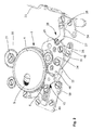
- the figure 1 represents a simplified front view of a watch movement according to a preferred embodiment of the present invention, in a bridge-side view.
- the watch movement is intended for the design of a timepiece comprising a rotary dial (visible on the figure 4 ) and therefore comprises a drive device of this rotary dial, housed in the bottom of the timepiece, illustratively non-limiting.
- the watch movement comprises a barrel 1 dedicated to driving the rotary dial and arranged substantially in the center of the movement.
- the latter furthermore comprises a device for controlling the drive device of the dial, visible on the part to the left of the figure 1 , a device for winding the mainspring, visible on the part to the right of the figure 1 , and a safety device, according to the present invention, whose function will be explained later in connection with the detailed description of the figure 5 .
- a shaft 2 for transmitting the energy supplied by the barrel to drive the mobile dial in rotation is also visible in the upper right corner of the figure 1 .
- the barrel 1 comprises a toothed drum 4 secured to the outer end of a barrel spring 5.
- a winding ratchet (marked with the numeral 6 on the figure 2 ) is integral with the inner end of the mainspring.
- a spring pawl 8 is arranged to prevent the winding ratchet from rotating in a clockwise direction, and to allow it to rotate in the anticlockwise rotation direction corresponding to the winding of the mainspring, in a conventional manner.
- a first latch 10 whose operation will be explained later locks the drum 4 to prevent it from rotating in the direction of rotation anti-clockwise.
- the winding device comprises a rack 12, actuated in translation by a pusher 14 intended to be itself actuated by a user, via an external pusher (not shown).
- the pusher 14 is pivotally mounted on a bridge, by means of a screw 15.
- the rack 12 has a toothing 19 arranged in engagement with a first wheel (reference numeral 94 on the figure 5 ) of a conventional unidirectional transmission device.
- this first wheel transmits its rotational movements to a second wheel of the device only in one direction, here in the direction of rotation anti-clockwise, while it rotates empty in the direction of clockwise rotation.
- the second wheel meshes with a pinion 21 of an adjacent return whose wheel 22 meshes with the winding ratchet 6.
- This control device comprises a pusher 24 rotatably mounted on the frame of the watch movement, by means of a screw 25.
- the return spring 23 has two symmetrical arms and is arranged to act also on the pusher 24. The latter is intended to be actuated by a user, via a second external pusher (not shown).
- the pusher 24 is integral with a control lever 26 comprising an arm 27 slightly bent and connected to a base 28, by means of a screw 29.
- the base is pivotally mounted on the frame of the watch movement by a first screw 30, while being guided in its rotational movements by a second screw 32 fixed in the frame but arranged through a short slot 34.
- the base 28 supports an actuating member 36 fixed on it by screws 38, tightened on screw feet and housed in slots adapted to the actuating member, allowing the latter to move in translation with reference at the base 28, between first and second positions, respectively active and inactive.
- An elastic member 40 is also provided to apply a force on a finger 41 integral with the actuating member to tend to push it back into its active position, that is to say advanced relative to the base 28.
- L elastic member 40 is mounted on a screw 42 integral with the base 28 to allow adjustment of the force it applies to the finger 41.
- the actuating member 36 carries first and second fingers 44, 45 arranged to protrude from the face of the base 28 opposite that on the side of the arm 27. Each of the fingers has an end inclined relative to the direction moving the actuating member with reference to the base 28.
- a pin 46 integral with the base 28, emerges between the two fingers 44, 45 to define a bearing surface intended to cooperate with an additional elastic member 48, mounted on the frame of the watch movement to apply a restoring force on the lever 26 and push it towards its rest position, that is to say in the direction of the pusher 24.
- the first and second fingers 44 and 45 are arranged to cooperate respectively with the first latch 10 and a second latch 50.
- the first latch 10 comprises a board rotatably mounted on a shaft 52 integral with the frame of the watch movement, with the interposition of a helical spring 54 defining a damping function.
- the board includes a first nose 56 intended to cooperate with the first finger 44, and a second nose 58 intended to cooperate with teeth 60 formed on a ring 62, integral with the drum 4 of the barrel 1, to lock the latter in the direction of rotation anti-clockwise on the view of the figure 1 , as previously stated.
- the ring 62 has four teeth 60 regularly distributed. Thus, each time the drum is released, it performs a quarter turn. When it is desired that this rotation of the drum takes place at a high speed, the barrel spring 5 then being calibrated in a suitable manner, the shock resulting from the locking of the ring 62 by the cooperation between the spout 58 and a tooth 60 can be violent. Thus, mounting the first latch 10 on the frame via a damper limits the risk of premature wear constituents of the watch movement according to the present invention.
- the barrel spring 5 has a high torque, it may be necessary to provide the second latch 50 to secure the locking of the drum 4 by the first latch 10, eliminating the risk of inadvertent release of the latter. Due to its arrangement, the second latch 50 prevents the first latch 10 from disengaging from the tooth 60 with which it is engaged without further external action.
- Soldering the barrel spring drum also prevents some damage that might be experienced by the components of the watch movement during these shocks.
- the finger 45 of the actuating member 36 is intended to actuate the second latch 50 via a abutment surface 64 formed on the latter. More precisely, when the push-button 24 is actuated by a user, the base 28 of the lever 26 is rotated, as is the actuating member 36 whose fingers 44 and 45 act respectively on the first and second locks, the finger 45 acting on the second lock before the finger 44 acts on the first lock. Thus, the safety of the first latch is neutralized before it is actuated to release the barrel drum.
- a return spring 66 having three arms acts on the first and second locks, to exert on them forces tending to position them in their active locking position, and on the pawl 8 of the winding ratchet, so known.
- a first safety device is provided.
- it has the form of a disengaging member 68 rotatably mounted on the frame of the watch movement, between the barrel drum and the lever 26.
- the disengaging member 68 comprises a toothed pinion 70 integral with a cam 72, of oblong shape and arranged eccentrically with reference to the axis of rotation of the pinion gear.
- the latter is dimensioned and toothed so that it turns on itself when the barrel 4 is a quarter turn.
- the fingers release the two latches 10 and 50 during the rotation of the drum 4, even when the pusher 24 is held down by the user, guaranteeing in all cases the locking of the drum barrel after a predefined stroke, a quarter of a turn in the embodiment shown in a non-limiting manner.
- the drum When the drum is released, it also drives a first transmission mobile 74 kinematically connected to a mobile, preferably display or contributing to the appearance of the room.
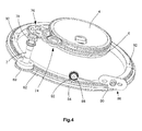
- the figure 4 represents a simplified perspective view of a preferred embodiment of a watch mechanism that can be driven from the barrel drum whose behavior has just been described.
- the first transmission mobile 74 is arranged in engagement with a second transmission mobile 76, itself engaged with a pinion 78 integral with the transmission shaft 2.
- the corresponding timepiece comprises a mobile dial having at least one window or window that can take four different angular positions, with reference to the timepiece box , in order to provide four different appearances to the room and / or present different complications of which only one would be visible at a time.
- a stabilizing member 86 may be provided, which comprises a roller 88 carried by the end of a spring 90.
- the roller 88 is arranged to cooperate with a recess 92 formed in the ring 82 to each of the stable positions provided for the mobile dial.
- the figure 5 represents a simplified perspective view of the part of the watchmaking movement of the figure 1 with construction details relative to the safety device according to the present invention, the implementation of which allows in particular to ensure the maintenance of the indexing of the mobile dial with respect to the elements that it must make visible or conceal, limiting the use of the mainspring to a suitable beach, in terms of load.
- the energy stored in the barrel is sufficient to allow several successive activations of the dial between two pumping. It may be preferable to provide that the safety device prevents the user from unlocking the barrel drum if the residual energy of its spring is no longer sufficient to guarantee its movement a quarter of a turn, which could lead to a phase shift of the mobile dial, or even make the latter floating angularly.
- the safety device comprises a differential gear 100, of which a first input wheel 101 has a kinematic connection with the winding ratchet 6 of the barrel, and a second input wheel 102 meshes directly with the drum 4 of the barrel.
- barrel 1 The first wheel 101 is connected to the winding ratchet 6 via a reference 104 for rotating the first input wheel 101 in the direction required to ensure the proper operation of the differential gear.
- the differential gear further has an output wheel 106 arranged in engagement with a gear train 108 for driving a first counting wheel 110 carrying a first cam 112, having substantially the shape of a disk portion, and a finger 114 adjacent to the cam.
- the first counting mobile 110 cooperates with a second counting mobile 116 comprising a toothing (not visible), arranged to move a locking wheel 118 between two extreme positions, and a second cam 120 having at least partially the shape of a Maltese cross with at least two branches 122, here four.
- the first cam 112 is arranged to cooperate with the free ends of the branches 122 to prevent rotation of the second counting wheel 116.
- the finger 114 is intended to engage between two branches 122 of the second counting mobile 116 to drive the latter in rotation, in one direction or the other.
- the toothing of the second counting mobile 116 is arranged in engagement with a rack (numerical reference 124 on the figure 1 ) to ensure the displacement of the locking wheel 118, either towards the first pusher 14 or towards the second pusher 24.
- the locking device 118 carries first and second arms 126, 128 intended to cooperate respectively with the first and second pushers 14, 24, to ensure locking, via nozzles 130, 131.
- an action on the first pusher 14 has the effect of raising the spring 5 of the cylinder 1
- an action on the second pusher 24 has the effect of releasing the drum 4 of the cylinder and thus at least partially unload the spring 5.
- the first arm 126 of the locking wheel 118 is disposed on the path followed by the spout 130 of the first pusher 14 when the latter is actuated. Therefore, the first pusher 14 is locked in this configuration and can not be operated by a user. Also, this configuration corresponds to the maximum winding of the spring 5 of the cylinder 1 and the user can not reassemble more.
- cam 112 also defines a stop for the first counting mobile 110 via the finger 114.
- the user wishes to turn the mobile support 84 by a quarter of a turn, he actuates the second pusher 24. In doing so, he releases the drum 4 which rotates a quarter of a turn and causes the rotating the second input wheel 102 of the differential gear 100.
- the rotation of the second wheel 102 causes a rotation of the first counting wheel 110 in the anti-clockwise direction of rotation.
- the angle of rotation of the first counting mobile 110 is a function of the gear ratio introduced in particular by the gear train 108.
- the first pusher 14 can again be operated once to raise the mainspring before being locked again.
- the second pusher 24 can still be actuated several times before being locked by the second arm 128 of the locking wheel 118, when it is positioned in the path of the spout 131. More specifically, in the example illustrated here without limitation, the second pusher 24 can still be actuated three times before being locked.
- the spring 5 it is possible for the spring 5 to be calibrated in such a way that it makes it possible to actuate the support mobile 84 84 times. In this case, the first counting mobile 110 would only be a half-turn each time the actuator is actuated. second pusher 24 instead of a complete turn.
- the arms 126, 128 are mounted on the locking wheel 118 with a slight play in rotation, springs 132 being provided to ensure their good cooperation with the pushers. More particularly, this construction makes it possible to guarantee a good positioning of the arms in their locking position. Indeed, when the mobile locking is placed in one or other of the locking positions, the push 14 or 24 corresponding is still actuated and is on the path of its locking arm 126 or 128. In this intermediate phase, the arm pivots by deforming its spring 132 until the pusher is released and allows the arm to be positioned in its locking position, under the effect of the spring.
- the arms could for example be carried by a support connected via an elastic member to a base of the locking wheel, driven from the output of the differential gear, so that all the support remains offset from the base in the intermediate phase, before taking its rest position when the pusher is released.
- the barrel can be used to ensure the operation of a striking mechanism as an alternative to a mobile dial.
- the forms specifically illustrated and described for the various constituents are not limiting.
- the disengaging member acts only indirectly on the actuating member.
- the teeth 60 cooperating with the first latch are not evenly distributed around the ring 62.
- the safety device could be associated with a power reserve indication device without departing from the scope of the invention.
- This indication device could be driven from any mobile located between the output of the differential gear, or alternatively, by the locking mobile itself, which would in this case to display the value of the power reserve opposite a linear scale.
Abstract
Description
La présente invention concerne un mécanisme horloger comportant
un barillet logeant un ressort de barillet dont les première et seconde extrémités sont respectivement solidaires d'une première denture, d'entrée, et d'une seconde denture, de sortie,
un premier organe de commande agencé pour permettre le remontage du ressort de barillet par l'intermédiaire de la première denture, et
un dispositif de sécurité agencé de telle manière qu'il assure au moins indirectement le verrouillage du premier organe de commande lorsque le ressort de barillet présente un niveau de charge supérieur à une première valeur prédéfinie.The present invention relates to a clock mechanism comprising
a barrel housing a barrel spring whose first and second ends are respectively integral with a first toothing, inlet, and a second toothing, outlet,
a first control member arranged to allow the winding of the mainspring by means of the first toothing, and
a safety device arranged in such a way that it at least indirectly ensures the locking of the first control member when the mainspring has a load level higher than a first predefined value.
Des mécanismes de ce type ont déjà été divulgués dans l'art antérieur, généralement connus sous la dénomination de systèmes d'arrêtage.Mechanisms of this type have already been disclosed in the prior art, generally known as stop systems.
A titre d'exemple, le
Un inconvénient de ces systèmes d'arrêtage réside dans le fait que le rouage de remontage situé entre un organe de commande externe actionné par un utilisateur et le barillet peut subir des dommages si l'utilisateur insiste une fois que le système d'arrêtage est en position bloquée.A disadvantage of these stop systems lies in the fact that the winding train located between an external control member actuated by a user and the barrel may be damaged if the user insists once the stop system is in operation. locked position.
Actuellement, pour remplacer ces systèmes d'arrêtage, l'extrémité externe du ressort de barillet est généralement rendue solidaire du tambour par l'intermédiaire d'une bride glissante, pour prévenir sa casse lorsqu'un utilisateur continue d'actionner l'organe de remontage alors que le ressort est complètement chargé.Currently, to replace these stop systems, the outer end of the mainspring is generally secured to the drum by means of a sliding flange, to prevent its breakage when a user continues to operate the winding member while the spring is fully loaded.
Un but principal de la présente invention est de proposer une alternative aux mécanismes connus de l'art antérieur, en proposant un dispositif de sécurité pour le remontage du ressort de barillet qui soit à la fois fiable et résistant et, qui soit en outre évolutif, autrement dit, qu'il puisse remplir d'autres fonctions.A main object of the present invention is to propose an alternative to the mechanisms known from the prior art, by proposing a safety device for winding the mainspring which is both reliable and resistant, and which is also scalable, in other words, that he can perform other functions.
A cet effet, la présente invention concerne plus particulièrement un mécanisme horloger du type mentionné plus haut, caractérisé par le fait qu'il comporte un engrenage différentiel comprenant
une première entrée présentant une première liaison cinématique avec la première denture,
une seconde entrée présentant une seconde liaison cinématique avec la seconde denture, et
une sortie présentant une troisième liaison cinématique avec le dispositif de sécurité pour commander ce dernier.For this purpose, the present invention relates more particularly to a clock mechanism of the type mentioned above, characterized in that it comprises a differential gear comprising
a first input presenting a first kinematic connection with the first toothing,
a second input having a second kinematic link with the second toothing, and
an output having a third kinematic link with the safety device for controlling the latter.
Grâce à ces caractéristiques, le dispositif de sécurité est déporté en référence au barillet, préférablement en un emplacement du mouvement horloger correspondant qui n'était pas occupé par la mise en oeuvre d'un autre mécanisme. En outre, la structure du mécanisme horloger selon l'invention permet éventuellement d'envisager son interaction avec des mécanismes additionnels du mouvement horloger correspondant.Thanks to these characteristics, the safety device is deported with reference to the barrel, preferably at a location of the corresponding clock movement that was not occupied by the implementation of another mechanism. In addition, the structure of the watchmaking mechanism according to the invention possibly allows to consider its interaction with additional mechanisms of the corresponding watch movement.
En effet, de manière avantageuse, ce mécanisme peut comporter un second organe de commande agencé pour libérer la seconde denture en réponse à une action prédéfinie d'un utilisateur, le dispositif de sécurité étant également agencé pour assurer au moins indirectement le verrouillage du second organe de commande lorsque le ressort de barillet présente un niveau de charge inférieur à une seconde valeur prédéfinie.Indeed, advantageously, this mechanism may comprise a second control member arranged to release the second toothing in response to a predefined action of a user, the safety device being also arranged to ensure at least indirectly the locking of the second member when the barrel spring has a load level lower than a second preset value.
Selon un mode de réalisation préféré, le dispositif de sécurité comporte un mobile de verrouillage dont les déplacements sont commandés à partir de la sortie de l'engrenage différentiel et présentant une première butée agencée pour verrouiller au moins indirectement le premier organe de commande lorsque le ressort de barillet présente un niveau de charge supérieur à la première valeur prédéfinie.According to a preferred embodiment, the safety device comprises a locking wheel whose displacements are controlled from the output of the differential gear and having a first stop arranged to lock at least indirectly the first gear member. control when the mainspring has a load level higher than the first preset value.
Plus particulièrement, le mobile de verrouillage peut comprendre une crémaillère dont les déplacements entre des première et seconde positions extrêmes sont commandés par un mobile entraîneur relié cinématiquement à la sortie de l'engrenage différentiel, la butée coopérant avec le premier organe de commande dans la première position de la crémaillère.More particularly, the locking wheel may comprise a rack whose movements between first and second extreme positions are controlled by a driving wheel connected kinematically to the output of the differential gear, the stop cooperating with the first control member in the first gear. rack position.
De manière avantageuse, le dispositif de sécurité peut également comprendre une seconde butée agencée pour verrouiller le second organe de commande lorsque le ressort de barillet présente un niveau de charge inférieur à la seconde valeur prédéfinie.Advantageously, the safety device may also comprise a second stop arranged to lock the second control member when the mainspring has a lower load level than the second preset value.
Grâce à ces caractéristiques, l'utilisation du ressort de barillet peut être optimisée en fonction de sa plage de fonctionnement.Thanks to these characteristics, the use of the mainspring can be optimized according to its operating range.
De manière préférée, le dispositif de sécurité peut comporter
un premier mobile de comptage relié cinématiquement à la sortie de l'engrenage différentiel et portant une première came présentant sensiblement la forme d'une portion de disque et un doigt adjacent à la came, et
un second mobile de comptage comprenant une denture agencée pour déplacer le mobile de verrouillage ainsi qu'une seconde came présentant au moins partiellement la forme d'une croix de Malte à au moins deux branches,
les premier et second mobiles de comptage étant agencés de telle manière que
la première came est susceptible de coopérer avec la seconde came pour bloquer la rotation du second mobile, et
le doigt est susceptible de coopérer avec la seconde came pour la faire tourner.Preferably, the security device may comprise
a first counting mobile connected kinematically to the output of the differential gear and carrying a first cam having substantially the shape of a disk portion and a finger adjacent to the cam, and
a second counting wheel comprising a toothing arranged to move the locking wheel and a second cam having at least partially the shape of a Maltese cross with at least two branches,
the first and second counting wheels being arranged in such a way that
the first cam is able to cooperate with the second cam to block the rotation of the second mobile, and
the finger is likely to cooperate with the second cam to rotate it.
Grâce à ces caractéristiques supplémentaires, le mécanisme selon l'invention garantit un haut niveau de sécurité associé à une faible consommation énergétique.Thanks to these additional features, the mechanism according to the invention guarantees a high level of security associated with low energy consumption.
Par ailleurs, le mobile de verrouillage peut porter un premier bras présentant une extrémité libre définissant la première butée et un premier organe élastique agencé pour agir sur le premier bras et tendre à positionner la première butée dans une position adaptée pour verrouiller le premier organe de commande.Furthermore, the locking mobile can carry a first arm having a free end defining the first stop and a first resilient member arranged to act on the first arm and tend to position the first stop in a position adapted to lock the first control member .
En outre, le mobile de verrouillage peut en outre porter un second bras présentant une extrémité libre définissant la seconde butée et un second organe élastique agencé pour agir sur le second bras et tendre à positionner la seconde butée dans une position adaptée pour verrouiller le second organe de commande.In addition, the locking mobile may further carry a second arm having a free end defining the second stop and a second elastic member arranged to act on the second arm and tend to position the second stop in a position adapted to lock the second member control.
La présente invention concerne également un mouvement horloger comportant un mécanisme répondant aux caractéristiques ci-dessus, dans lequel la seconde denture présente
une liaison cinématique avec un organe d'affichage mobile et un positionnement angulaire indexé au positionnement angulaire de l'organe d'affichage mobile.The present invention also relates to a watch movement comprising a mechanism corresponding to the above characteristics, in which the second toothing presents
a kinematic connection with a movable display member and an angular positioning indexed to the angular positioning of the movable display member.
Selon un mode de réalisation préféré de la présente invention, l'organe d'affichage mobile peut être un cadran rotatif.According to a preferred embodiment of the present invention, the movable display member may be a rotary dial.
En alternative, le mouvement horloger peut comporter un mécanisme de sonnerie destiné à être actionné à partir d'un barillet spécifique associé à un dispositif de sécurité selon la présente invention.Alternatively, the watch movement may comprise a striking mechanism intended to be actuated from a specific barrel associated with a safety device according to the present invention.
D'autres caractéristiques et avantages de la présente invention apparaîtront plus clairement à la lecture de la description détaillée d'un mode de réalisation préféré qui suit, faite en référence aux dessins annexés donnés à titre d'exemples non limitatifs et dans lesquels:Other features and advantages of the present invention will appear more clearly on reading the detailed description of a preferred embodiment which follows, made with reference to the accompanying drawings given by way of non-limiting examples and in which:
- la
- la
- la
- la
- la
La
Selon le présent mode de réalisation, le mouvement horloger est destiné à la conception d'une pièce d'horlogerie comportant un cadran rotatif (visible sur la
Il apparaît de la
Ce dernier comporte par ailleurs un dispositif de commande du dispositif d'entraînement du cadran, visible sur la partie à gauche de la
Un arbre 2 de transmission de l'énergie fournie par le barillet pour entraîner le cadran mobile en rotation est également visible dans le coin supérieur droit de la
La construction du dispositif de remontage va être décrite plus en détail, à présent, en relation avec la
Le barillet 1 comporte un tambour 4 denté solidaire de l'extrémité externe d'un ressort 5 de barillet. De manière avantageuse non limitative, il peut être préférable de rendre le ressort et le tambour solidaires l'un de l'autre, par exemple par soudage, pour des raisons qui seront exposées plus loin. Un rochet de remontage (repéré avec la référence numérique 6 sur la
Par ailleurs, un premier verrou 10 dont le fonctionnement sera exposé plus loin verrouille le tambour 4 pour l'empêcher de tourner dans le sens de rotation anti-horaire.Furthermore, a
Le dispositif de remontage comprend une crémaillère 12, actionnée en translation par un poussoir 14 destiné à être lui-même actionné par un utilisateur, par l'intermédiaire d'un poussoir externe (non illustré). Le poussoir 14 est monté pivotant sur un pont, au moyen d'une vis 15.The winding device comprises a
La crémaillère 12 présente une denture 19 agencée en prise avec une première roue (référence numérique 94 sur la
La seconde roue engrène avec un pignon 21 d'un renvoi adjacent dont la roue 22 engrène avec le rochet de remontage 6.The second wheel meshes with a
Ainsi, lorsque la crémaillère 12 est déplacée vers le haut de la
Un exemple illustratif et non limitatif de dispositif de commande, destiné à actionner le dispositif d'entraînement du cadran rotatif, va à présent être détaillé en relation avec les
Ce dispositif de commande comporte un poussoir 24 monté rotatif sur le bâti du mouvement horloger, au moyen d'une vis 25. On notera que le ressort de rappel 23 présente deux bras symétriques et est agencé pour agir également sur le poussoir 24. Ce dernier est destiné à être actionné par un utilisateur, par l'intermédiaire d'un second poussoir externe (non illustré).This control device comprises a
Le poussoir 24 est solidaire d'un levier de commande 26 comprenant un bras 27 légèrement coudé et relié à une base 28, au moyen d'une vis 29. La base est montée pivotante sur le bâti du mouvement horloger par une première vis 30, tout en étant guidée dans ses déplacements en rotation par une seconde vis 32 fixée dans le bâti mais disposée au travers d'une courte fente 34.The
La base 28 supporte un organe d'actionnement 36 fixé sur elle par des vis 38, serrées sur des pieds-vis et, logées dans des fentes adaptées de l'organe d'actionnement, permettant à ce dernier de se déplacer en translation en référence à la base 28, entre des première et seconde positions, respectivement active et inactive. Un organe élastique 40 est par ailleurs prévu pour appliquer une force sur un doigt 41 solidaire de l'organe d'actionnement pour tendre à le repousser dans sa position active, c'est-à-dire avancée par rapport à la base 28. L'organe élastique 40 est monté sur une vis 42 solidaire de la base 28 pour permettre un ajustement de la force qu'il applique sur le doigt 41.The
L'organe d'actionnement 36 porte des premier et second doigts 44, 45 disposés de manière à dépasser de la face de la base 28 opposée à celle située du côté du bras 27. Chacun des doigts présente une extrémité inclinée par rapport à la direction de déplacement de l'organe d'actionnement en référence à la base 28.The actuating
Une goupille 46, solidaire de la base 28, émerge entre les deux doigts 44, 45 pour définir une surface d'appui destinée à coopérer avec un organe élastique supplémentaire 48, monté sur le bâti du mouvement horloger pour appliquer une force de rappel sur le levier 26 et le repousser vers sa position de repos, c'est-à-dire en direction du poussoir 24.A
Les premier et second doigts 44 et 45 sont agencés pour coopérer respectivement avec le premier verrou 10 et un second verrou 50.The first and
Le premier verrou 10 comporte une planche montée rotative sur un arbre 52 solidaire du bâti du mouvement horloger, avec interposition d'un ressort hélicoïdal 54 définissant une fonction d'amortisseur.The
La planche comprend un premier bec 56 destiné à coopérer avec le premier doigt 44, ainsi qu'un second bec 58 destiné à coopérer avec des dents 60 ménagées sur une bague 62, solidaire du tambour 4 du barillet 1, pour verrouiller ce dernier dans le sens de rotation anti-horaire sur la vue de la
Il ressort de la
De même, lorsque le ressort 5 de barillet présente un couple important, il peut être nécessaire de prévoir le second verrou 50 pour sécuriser le verrouillage du tambour 4 par le premier verrou 10, en éliminant les risques de dégagement intempestif de ce dernier. Du fait de son agencement, le second verrou 50 empêche le premier verrou 10 de se dégager de la dent 60 avec laquelle il est en prise sans autre action extérieure.Similarly, when the
Le fait de souder le ressort de barillet au tambour permet également de prévenir certains dommages que pourraient subir les constituants du mouvement horlogers lors de ces chocs.Soldering the barrel spring drum also prevents some damage that might be experienced by the components of the watch movement during these shocks.
Il apparaît de ce qui précède que le doigt 45 de l'organe d'actionnement 36 est destiné à actionner le second verrou 50 par l'intermédiaire d'une surface de butée 64 ménagée sur ce dernier. Plus précisément, lors de l'actionnement du poussoir 24 par un utilisateur, la base 28 du levier 26 est entraînée en rotation, de même que l'organe d'actionnement 36 dont les doigts 44 et 45 vont agir respectivement sur les premier et second verrous, le doigt 45 agissant sur le second verrou avant que le doigt 44 n'agisse sur le premier verrou. Ainsi, la sécurité du premier verrou est neutralisée avant qu'il ne soit actionné pour libérer le tambour de barillet.It appears from the above that the
On notera qu'un ressort de rappel 66 présentant trois bras agit sur les premier et second verrous, pour exercer sur eux des forces tendant à les positionner dans leur position active de verrouillage, ainsi que sur le cliquet 8 du rochet de remontage, de manière connue.Note that a
Pour éviter que le premier verrou 10 ne reste dans sa position inactive, du fait d'une action prolongée de l'utilisateur sur le poussoir 24, c'est-à-dire lorsque la durée de cette action excède le temps nécessaire au tambour de barillet pour effectuer un quart de tour, un premier dispositif de sécurité est prévu. Celui-ci présente ici la forme d'un organe de débrayage 68 monté rotatif sur le bâti du mouvement horloger, entre le tambour de barillet et le levier 26.To prevent the
L'organe de débrayage 68 comprend un pignon denté 70 solidaire d'une came 72, de forme oblongue et, agencée de manière excentrée en référence à l'axe de rotation du pignon denté. Ce dernier est dimensionné et denté de telle manière qu'il fait un tour sur lui-même lorsque le barillet 4 fait un quart de tour. Lorsque le tambour de barillet est libéré par le premier verrou 10, suite à une pression sur le poussoir 24, il entraîne l'organe de débrayage 68 en rotation, dont la came 72 agit sur l'organe d'actionnement 36 pour le repousser en direction de la base 28 et rétracter les premier et second doigts 44, 45. Grâce à cette construction, les doigts libèrent les deux verrous 10 et 50 pendant la rotation du tambour 4, même lorsque le poussoir 24 est maintenu enfoncé par l'utilisateur, garantissant dans tous les cas le verrouillage du tambour de barillet après une course prédéfinie, d'un quart de tour dans le mode de réalisation illustré à titre non limitatif.The disengaging
Lorsque le tambour est libéré, il entraîne également un premier mobile de transmission 74 relié cinématiquement à un mobile, préférablement d'affichage ou contribuant à l'apparence de la pièce.When the drum is released, it also drives a first transmission mobile 74 kinematically connected to a mobile, preferably display or contributing to the appearance of the room.
La
Le premier mobile de transmission 74 est agencé en prise avec un second mobile de transmission 76, lui-même en prise avec un pignon 78 solidaire de l'arbre 2 de transmission.The
Ce dernier porte un pignon supplémentaire 80 à son extrémité opposée, située du côté platine du mouvement horloger. Ce dernier est agencé en prise avec une bague dentée 82 destinée à être solidaire d'un mobile support 84, mobile en rotation et, destiné par exemple à porter un cadran. En particulier, on peut prévoir dans un mode de réalisation préféré que la pièce d'horlogerie correspondante comprend un cadran mobile présentant au moins un guichet ou une fenêtre qui peut prendre quatre positions angulaires différentes, en référence à la boîte de la pièce d'horlogerie, dans le but de procurer quatre apparences différentes à la pièce et/ou présenter des complications différentes dont une seule serait visible à la fois.The latter carries an
Un exemple d'une telle pièce d'horlogerie est divulgué dans le brevet
A titre indicatif, un organe de stabilisation 86 peut être prévu, celui-ci comprenant un galet 88 porté par l'extrémité d'un ressort 90. Le galet 88 est agencé de manière à coopérer avec une creusure 92 ménagée dans la bague 82 pour chacune des positions stables prévues pour le cadran mobile.As an indication, a stabilizing
Bien entendu, le nombre de positions décrit pour le cadran mobile est indicatif et non limitatif. De manière avantageuse, il devrait pouvoir en prendre deux différentes au minimum, mais pourrait en présenter plus que quatre en alternative, sans sortir du cadre de l'invention.Of course, the number of positions described for the mobile dial is indicative and not limiting. Advantageously, it should be able to take two different minimum, but could present more than four alternative, without departing from the scope of the invention.
La
Suivant un mode de réalisation préféré de l'invention, on peut prévoir que l'énergie stockée dans le barillet est suffisante pour permettre plusieurs activations successives du cadran entre deux remontages. Il peut être préférable de prévoir que le dispositif de sécurité empêche l'utilisateur de déverrouiller le tambour de barillet si l'énergie résiduelle de son ressort n'est plus suffisante pour garantir son déplacement d'un quart de tour, ce qui pourrait conduire à un déphasage du cadran mobile, voire rendre ce dernier flottant angulairement.According to a preferred embodiment of the invention, it can be provided that the energy stored in the barrel is sufficient to allow several successive activations of the dial between two pumping. It may be preferable to provide that the safety device prevents the user from unlocking the barrel drum if the residual energy of its spring is no longer sufficient to guarantee its movement a quarter of a turn, which could lead to a phase shift of the mobile dial, or even make the latter floating angularly.
Dans ce but, le dispositif de sécurité comporte un engrenage différentiel 100, dont une première roue d'entrée 101 présente une liaison cinématique avec le rochet de remontage 6 du barillet et, une seconde roue d'entrée 102 engrène directement avec le tambour 4 du barillet 1. La première roue 101 est reliée au rochet de remontage 6 par l'intermédiaire d'un renvoi 104 permettant de faire tourner la première roue d'entrée 101 dans le sens requis pour assurer le bon fonctionnement de l'engrenage différentiel.For this purpose, the safety device comprises a
L'engrenage différentiel présente en outre une roue de sortie 106 agencée en prise avec un train d'engrenages 108 destiné à entraîner un premier mobile de comptage 110 portant une première came 112, présentant sensiblement la forme d'une portion de disque, et un doigt 114 adjacent à la came.The differential gear further has an
Le premier mobile de comptage 110 coopère avec un second mobile de comptage 116 comprenant une denture (non visible), agencée pour déplacer un mobile de verrouillage 118 entre deux positions extrêmes, ainsi qu'une seconde came 120 présentant au moins partiellement la forme d'une croix de Malte à au moins deux branches 122, ici quatre.The
La première came 112 est agencée de manière à coopérer avec les extrémités libres des branches 122 pour empêcher une rotation du second mobile de comptage 116.The
Le doigt 114 est destiné à s'engager entre deux branches 122 du second mobile de comptage 116 pour entraîner ce dernier en rotation, dans un sens ou dans l'autre.The
La denture du second mobile de comptage 116 est agencée en prise avec une crémaillère (référence numérique 124 sur la
Le mobile de verrouillage 118 porte des premier et second bras 126, 128 destinés à coopérer respectivement avec les premier et second poussoirs 14, 24, pour en assurer le verrouillage, via des becs 130, 131.The
Le fonctionnement du dispositif de sécurité va maintenant être exposé en relation avec la
Pour rappel, une action sur le premier poussoir 14 a pour effet de remonter le ressort 5 du barillet 1, tandis qu'une action sur le second poussoir 24 a pour effet de libérer le tambour 4 du barillet et donc de décharger au moins partiellement le ressort 5.As a reminder, an action on the
Dans la configuration illustrée sur la
On notera par ailleurs que la came 112 définit également un arrêt pour le premier mobile de comptage 110 par l'intermédiaire du doigt 114.Note also that the
Si, partant de cette configuration, l'utilisateur souhaite faire tourner le mobile support 84 d'un quart de tour, il actionne le second poussoir 24. Ce faisant, il libère le tambour 4 qui tourne d'un quart de tour et entraîne la rotation de la seconde roue d'entrée 102 de l'engrenage différentiel 100.If, based on this configuration, the user wishes to turn the
La rotation de la seconde roue 102 entraîne une rotation du premier mobile de comptage 110 dans le sens de rotation anti-horaire.The rotation of the
L'angle de rotation du premier mobile de comptage 110 est fonction de la démultiplication introduite notamment par le train d'engrenages 108.The angle of rotation of the
Admettons, à titre d'exemple non limitatif et pour simplifier les présentes explications, qu'une rotation d'un quart de tour du tambour de barillet entraîne une rotation d'un tour complet du premier mobile de comptage 110. Dans ce cas, le doigt 114 pénètre dans l'espace situé entre deux branches 122 de la seconde came 120, lors de la fin de la course du premier mobile de comptage, pour faire tourner cette dernière d'un pas dans le sens horaire (le pas étant défini ici par les branches 122). La rotation du second mobile de comptage 116 dans le sens horaire induit un déplacement de la crémaillère 124 en direction du second poussoir 24, libérant ainsi le premier poussoir 14.As a nonlimiting example and to simplify the present explanations, let us suppose that a rotation of a quarter turn of the barrel drum causes rotation of a complete revolution of the
A partir de là, le premier poussoir 14 peut à nouveau être actionné une fois pour remonter le ressort de barillet avant d'être à nouveau verrouillé.From there, the
A l'inverse, le second poussoir 24 peut encore être actionné plusieurs fois avant d'être verrouillé par le second bras 128 du mobile de verrouillage 118, lorsque celui-ci vient se positionner sur le trajet du bec 131. Plus précisément, dans l'exemple illustré ici à titre non limitatif, le second poussoir 24 peut encore être actionné trois fois avant d'être verrouillé.Conversely, the
Bien entendu, l'homme du métier ne rencontrera pas de difficulté particulière pour adapter le dispositif de sécurité aux propriétés du ressort 5 de barillet. On peut par exemple prévoir que le ressort 5 est calibré de telle manière qu'il permet d'actionner huit fois la rotation du mobile support 84. Dans ce cas, le premier mobile de comptage 110 ne ferait qu'un demitour à chaque actionnement du second poussoir 24 à la place d'un tour complet.Of course, those skilled in the art will not encounter any particular difficulty in adapting the safety device to the properties of the barrel spring. For example, it is possible for the
On notera que les bras 126, 128 sont montés sur le mobile de verrouillage 118 en présentant un léger jeu en rotation, des ressorts 132 étant prévus pour assurer leur bonne coopération avec les poussoirs. Plus particulièrement, cette construction permet de garantir une bonne mise en place des bras dans leur position de verrouillage. En effet, lorsque le mobile de verrouillage vient se placer dans l'une ou l'autre des positions de verrouillage, le poussoir 14 ou 24 correspondant est encore actionné et se trouve sur le trajet de son bras de verrouillage 126 ou 128. Dans cette phase intermédiaire, le bras pivote en déformant son ressort 132 jusqu'à ce que le poussoir soit libéré et permette au bras de se positionner dans sa position de verrouillage, sous l'effet du ressort.Note that the
Bien entendu, il est possible de prévoir l'agencement d'un organe élastique de manière alternative pour parvenir au même résultat. Ainsi, les bras pourraient par exemple être portés par un support relié via un organe élastique à une base du mobile de verrouillage, entraînée à partir de la sortie de l'engrenage différentiel, de telle manière que tout le support reste décalé par rapport à la base dans la phase intermédiaire, avant de prendre sa position de repos lorsque le poussoir est libéré.Of course, it is possible to provide the arrangement of an elastic member alternately to achieve the same result. Thus, the arms could for example be carried by a support connected via an elastic member to a base of the locking wheel, driven from the output of the differential gear, so that all the support remains offset from the base in the intermediate phase, before taking its rest position when the pusher is released.
La description qui précède s'attache à décrire un mode de réalisation particulier à titre d'illustration non limitative et, l'invention n'est pas limitée à la mise en oeuvre de certaines caractéristiques particulières qui viennent d'être décrites, comme par exemple la structure de l'organe de commande, celle du mécanisme de remontage, ou encore le fait que le barillet est destiné à entraîner un cadran mobile. En effet, il est possible de mettre en oeuvre la présente invention pour que le dispositif de sécurité agisse au moins indirectement sur l'organe de remontage, de manière générale, pour le verrouiller, sans sortir du cadre de la présente invention.The foregoing description attempts to describe a particular embodiment by way of non-limiting illustration and the invention is not limited to the implementation of certain particular features which have just been described, for example the structure of the control member, that of the winding mechanism, or the fact that the barrel is intended to drive a mobile dial. Indeed, it is possible to implement the present invention so that the safety device acts at least indirectly on the winding member, in general, to lock, without departing from the scope of the present invention.
A titre d'exemple non limitatif, le barillet peut être mis à profit pour assurer le fonctionnement d'un mécanisme de sonnerie en alternative à un cadran mobile.By way of non-limiting example, the barrel can be used to ensure the operation of a striking mechanism as an alternative to a mobile dial.
Par ailleurs, les formes spécifiquement illustrées et décrites pour les différents constituants ne sont pas limitatives. A titre d'exemple, il est possible de prévoir que l'organe de débrayage n'agit que de façon indirecte sur l'organe d'actionnement. Par ailleurs, il est également possible de prévoir que les dents 60 coopérant avec le premier verrou ne soient pas réparties de manière régulière autour de la bague 62.Moreover, the forms specifically illustrated and described for the various constituents are not limiting. For example, it is possible to provide that the disengaging member acts only indirectly on the actuating member. Moreover, it is also possible to provide that the
L'homme du métier ne rencontrera pas de difficulté particulière pour adapter le contenu de la présente divulgation à ses propres besoins, et mettre en oeuvre un dispositif de commande ne reprenant qu'en partie les caractéristiques exposées ici, sans sortir du cadre de la présente invention.Those skilled in the art will not encounter any particular difficulty in adapting the content of the present disclosure to their own needs, and implement a control device that only partially replicates the features described herein without departing from the scope of the present invention.
Bien entendu, le dispositif de sécurité pourrait être associé à un dispositif d'indication de la réserve de marche sans sortir du cadre de l'invention. Ce dispositif d'indication pourrait être entraîné à partir de n'importe quel mobile situé entre la sortie de l'engrenage différentiel, voire en alternative, par le mobile de verrouillage lui-même, qui permettrait dans ce cas d'afficher la valeur de la réserve de marche en regard d'une échelle linéaire.Of course, the safety device could be associated with a power reserve indication device without departing from the scope of the invention. This indication device could be driven from any mobile located between the output of the differential gear, or alternatively, by the locking mobile itself, which would in this case to display the value of the power reserve opposite a linear scale.
Claims (15)
un barillet (1) logeant un ressort (5) de barillet dont les première et seconde extrémités sont respectivement solidaires d'une première denture (6), d'entrée, et d'une seconde denture (4), de sortie,
un premier organe de commande (12, 14) agencé pour permettre le remontage dudit ressort de barillet par l'intermédiaire de ladite première denture, et
un dispositif de sécurité (110, 116, 118) agencé de telle manière qu'il assure au moins indirectement le verrouillage dudit premier organe de commande (12, 14) lorsque ledit ressort (5) de barillet présente un niveau de charge supérieur à une première valeur prédéfinie,
caractérisé en ce qu'il comporte un engrenage différentiel (100) comprenant
une première entrée (101) présentant une première liaison cinématique avec ladite première denture (6),
une seconde entrée (102) présentant une seconde liaison cinématique avec ladite seconde denture (4), et
une sortie (106) présentant une troisième liaison cinématique avec ledit dispositif de sécurité (110, 116, 118) pour commander ce dernier.Watchmaking mechanism comprising
a barrel (1) housing a spring (5) barrel whose first and second ends are respectively integral with a first toothing (6), inlet, and a second toothing (4), output,
a first control member (12, 14) arranged to allow said barrel spring to be reassembled through said first toothing, and
a safety device (110, 116, 118) arranged in such a way that it at least indirectly locks said first control member (12, 14) when said barrel spring (5) has a load level greater than one first predefined value,
characterized in that it comprises a differential gear (100) comprising
a first input (101) presenting a first kinematic connection with said first toothing (6),
a second input (102) having a second kinematic link with said second toothing (4), and
an output (106) having a third kinematic link with said safety device (110, 116, 118) for controlling the latter.
un premier mobile de comptage (110) relié cinématiquement à ladite sortie (106) dudit engrenage différentiel (100) et portant une première came (112) présentant sensiblement la forme d'une portion de disque et un doigt (114) adjacent à ladite came, et
un second mobile de comptage (116) comprenant une denture agencée pour déplacer ledit mobile de verrouillage (118) ainsi qu'une seconde came (120) présentant au moins partiellement la forme d'une croix de Malte à au moins deux branches (122),
lesdits premier et second mobiles de comptage (110, 116) étant agencés de telle manière que
ladite première came (112) est susceptible de coopérer avec ladite seconde came (120) pour bloquer la rotation dudit second mobile de comptage (116), et
ledit doigt (114) est susceptible de coopérer avec ladite seconde came (120) pour la faire tourner.Mechanism according to any one of claims 3 to 6, characterized in that said safety device (110, 116, 118) comprises
a first counting mobile (110) kinematically connected to said output (106) of said differential gear (100) and carrying a first cam (112) having substantially the shape of a disk portion and a finger (114) adjacent said cam , and
a second counting wheel (116) comprising a toothing arranged to move said locking wheel (118) and a second cam (120) having at least partially the shape of a Maltese cross to at least two arms (122) ,
said first and second counting mobiles (110, 116) being arranged in such a way that
said first cam (112) is engageable with said second cam (120) to block the rotation of said second counting wheel (116), and
said finger (114) is capable of cooperating with said second cam (120) to rotate it.
Priority Applications (1)
| Application Number | Priority Date | Filing Date | Title |
|---|---|---|---|
| EP11159128A EP2503403A1 (en) | 2011-03-22 | 2011-03-22 | Security device for horological barrel |
Applications Claiming Priority (1)
| Application Number | Priority Date | Filing Date | Title |
|---|---|---|---|
| EP11159128A EP2503403A1 (en) | 2011-03-22 | 2011-03-22 | Security device for horological barrel |
Publications (1)
| Publication Number | Publication Date |
|---|---|
| EP2503403A1 true EP2503403A1 (en) | 2012-09-26 |
Family
ID=44581809
Family Applications (1)
| Application Number | Title | Priority Date | Filing Date |
|---|---|---|---|
| EP11159128A Withdrawn EP2503403A1 (en) | 2011-03-22 | 2011-03-22 | Security device for horological barrel |
Country Status (1)
| Country | Link |
|---|---|
| EP (1) | EP2503403A1 (en) |
Citations (4)
| Publication number | Priority date | Publication date | Assignee | Title |
|---|---|---|---|---|
| CH319289A (en) * | 1954-07-10 | 1957-02-15 | Reymond Paul E | Automatic winder for timepiece |
| CH333401A (en) * | 1955-10-28 | 1958-10-15 | E Reymond Paul | Automatic winder for timepiece |
| CH337786A (en) * | 1957-02-09 | 1959-04-15 | Gruen Watch Mfg Co S A | Self-winding watch |
| EP1840680B1 (en) | 2006-03-29 | 2008-06-25 | De Grisogono S.A. | Clock module including an adjustable rotary dial on a clock movement |
-
2011
- 2011-03-22 EP EP11159128A patent/EP2503403A1/en not_active Withdrawn
Patent Citations (5)
| Publication number | Priority date | Publication date | Assignee | Title |
|---|---|---|---|---|
| CH319289A (en) * | 1954-07-10 | 1957-02-15 | Reymond Paul E | Automatic winder for timepiece |
| FR1146549A (en) * | 1954-07-10 | 1957-11-13 | Automatic winder for timepiece | |
| CH333401A (en) * | 1955-10-28 | 1958-10-15 | E Reymond Paul | Automatic winder for timepiece |
| CH337786A (en) * | 1957-02-09 | 1959-04-15 | Gruen Watch Mfg Co S A | Self-winding watch |
| EP1840680B1 (en) | 2006-03-29 | 2008-06-25 | De Grisogono S.A. | Clock module including an adjustable rotary dial on a clock movement |
Non-Patent Citations (1)
| Title |
|---|
| G.-A. BERNER: "Dictionnaire", SOCIÉTÉ DU JOURNAL LA SUISSE HORLOGÈRE SA |
Similar Documents
| Publication | Publication Date | Title |
|---|---|---|
| EP2329325B1 (en) | Display mechanism for a timepiece used to display or not the current time | |
| EP2073076A1 (en) | Alarm clock control mechanism | |
| CH703008A1 (en) | Mechanism chronographe, clock and movement timepiece including such mechanism. | |
| CH702803A2 (en) | Displayed information e.g. date information, correcting mechanism for watch movement, has push button pivoting base of control lever in response to predefined action of user such that arm actuates one of correction levers | |
| EP2813902A1 (en) | Calendar mechanism for a clockwork | |
| CH703361A2 (en) | Movement clock having chronograph functions and account-a-down. | |
| EP3602202B1 (en) | Device for adjusting functions of a timepiece | |
| EP2615503B1 (en) | Barrel control mechanism for timepiece movement | |
| EP2503408B1 (en) | Control device for clock movement | |
| EP1960843A2 (en) | Timepiece movement | |
| EP2503403A1 (en) | Security device for horological barrel | |
| EP3407142B1 (en) | Timepiece movement with stop second function | |
| EP1960846A2 (en) | Clockwork movement | |
| CH708902B1 (en) | Timepiece comprising an animation device comprising a praxinoscope system. | |
| EP2503406B1 (en) | Shock-absorber device for clock mechanism | |
| EP2710433A1 (en) | Actuating mechanism for a timepiece movement and corresponding timepiece movement | |
| EP2339414A1 (en) | Chronograph with single push button | |
| CH711679A2 (en) | Mobile programming for watch movement. | |
| CH717359B1 (en) | Device for triggering a watch mechanism. | |
| CH710892B1 (en) | Chronograph mechanism for watch movement. | |
| FR3023934A1 (en) | WATCHMAKING MECHANISM | |
| CH718458A9 (en) | Actuation mechanism for a watch movement, in particular a chronograph mechanism comprising such an actuation mechanism. | |
| CH702992A1 (en) | Chronograph mechanism for clockwork movement utilized to drive i.e. needle, to display chronometered time, has counter associated with display member and arranged in such way that mobile part exhibits relative movement with counter | |
| CH713585B1 (en) | Multiple input control device for watch movement. | |
| CH700605A1 (en) | Horlogical movement for wristwatch, has drive units driving additional indicator units for displaying hour and minute of temporal period, and regulation units activated by user and acting on alarm gear train for regulating value of period |
Legal Events
| Date | Code | Title | Description |
|---|---|---|---|
| PUAI | Public reference made under article 153(3) epc to a published international application that has entered the european phase |
Free format text: ORIGINAL CODE: 0009012 |
|
| AK | Designated contracting states |
Kind code of ref document: A1 Designated state(s): AL AT BE BG CH CY CZ DE DK EE ES FI FR GB GR HR HU IE IS IT LI LT LU LV MC MK MT NL NO PL PT RO RS SE SI SK SM TR |
|
| AX | Request for extension of the european patent |
Extension state: BA ME |
|
| 17P | Request for examination filed |
Effective date: 20130204 |
|
| STAA | Information on the status of an ep patent application or granted ep patent |
Free format text: STATUS: THE APPLICATION IS DEEMED TO BE WITHDRAWN |
|
| 18D | Application deemed to be withdrawn |
Effective date: 20161001 |