EP2502784A1 - Fahrzeugleuchte, insbesondere zur Beleuchtung des Innenraums des Fahrzeugs - Google Patents
Fahrzeugleuchte, insbesondere zur Beleuchtung des Innenraums des Fahrzeugs Download PDFInfo
- Publication number
- EP2502784A1 EP2502784A1 EP12001791A EP12001791A EP2502784A1 EP 2502784 A1 EP2502784 A1 EP 2502784A1 EP 12001791 A EP12001791 A EP 12001791A EP 12001791 A EP12001791 A EP 12001791A EP 2502784 A1 EP2502784 A1 EP 2502784A1
- Authority
- EP
- European Patent Office
- Prior art keywords
- light
- region
- vehicle lamp
- emission
- light source
- Prior art date
- Legal status (The legal status is an assumption and is not a legal conclusion. Google has not performed a legal analysis and makes no representation as to the accuracy of the status listed.)
- Granted
Links
Images


Classifications
-
- G—PHYSICS
- G02—OPTICS
- G02B—OPTICAL ELEMENTS, SYSTEMS OR APPARATUS
- G02B6/00—Light guides; Structural details of arrangements comprising light guides and other optical elements, e.g. couplings
- G02B6/0001—Light guides; Structural details of arrangements comprising light guides and other optical elements, e.g. couplings specially adapted for lighting devices or systems
- G02B6/0011—Light guides; Structural details of arrangements comprising light guides and other optical elements, e.g. couplings specially adapted for lighting devices or systems the light guides being planar or of plate-like form
- G02B6/0033—Means for improving the coupling-out of light from the light guide
- G02B6/0035—Means for improving the coupling-out of light from the light guide provided on the surface of the light guide or in the bulk of it
- G02B6/0038—Linear indentations or grooves, e.g. arc-shaped grooves or meandering grooves, extending over the full length or width of the light guide
-
- B—PERFORMING OPERATIONS; TRANSPORTING
- B60—VEHICLES IN GENERAL
- B60Q—ARRANGEMENT OF SIGNALLING OR LIGHTING DEVICES, THE MOUNTING OR SUPPORTING THEREOF OR CIRCUITS THEREFOR, FOR VEHICLES IN GENERAL
- B60Q3/00—Arrangement of lighting devices for vehicle interiors; Lighting devices specially adapted for vehicle interiors
- B60Q3/60—Arrangement of lighting devices for vehicle interiors; Lighting devices specially adapted for vehicle interiors characterised by optical aspects
- B60Q3/62—Arrangement of lighting devices for vehicle interiors; Lighting devices specially adapted for vehicle interiors characterised by optical aspects using light guides
- B60Q3/64—Arrangement of lighting devices for vehicle interiors; Lighting devices specially adapted for vehicle interiors characterised by optical aspects using light guides for a single lighting device
-
- B—PERFORMING OPERATIONS; TRANSPORTING
- B60—VEHICLES IN GENERAL
- B60Q—ARRANGEMENT OF SIGNALLING OR LIGHTING DEVICES, THE MOUNTING OR SUPPORTING THEREOF OR CIRCUITS THEREFOR, FOR VEHICLES IN GENERAL
- B60Q3/00—Arrangement of lighting devices for vehicle interiors; Lighting devices specially adapted for vehicle interiors
- B60Q3/60—Arrangement of lighting devices for vehicle interiors; Lighting devices specially adapted for vehicle interiors characterised by optical aspects
- B60Q3/62—Arrangement of lighting devices for vehicle interiors; Lighting devices specially adapted for vehicle interiors characterised by optical aspects using light guides
- B60Q3/66—Arrangement of lighting devices for vehicle interiors; Lighting devices specially adapted for vehicle interiors characterised by optical aspects using light guides for distributing light among several lighting devices
-
- F—MECHANICAL ENGINEERING; LIGHTING; HEATING; WEAPONS; BLASTING
- F21—LIGHTING
- F21S—NON-PORTABLE LIGHTING DEVICES; SYSTEMS THEREOF; VEHICLE LIGHTING DEVICES SPECIALLY ADAPTED FOR VEHICLE EXTERIORS
- F21S43/00—Signalling devices specially adapted for vehicle exteriors, e.g. brake lamps, direction indicator lights or reversing lights
- F21S43/20—Signalling devices specially adapted for vehicle exteriors, e.g. brake lamps, direction indicator lights or reversing lights characterised by refractors, transparent cover plates, light guides or filters
- F21S43/235—Light guides
- F21S43/242—Light guides characterised by the emission area
- F21S43/245—Light guides characterised by the emission area emitting light from one or more of its major surfaces
-
- F—MECHANICAL ENGINEERING; LIGHTING; HEATING; WEAPONS; BLASTING
- F21—LIGHTING
- F21S—NON-PORTABLE LIGHTING DEVICES; SYSTEMS THEREOF; VEHICLE LIGHTING DEVICES SPECIALLY ADAPTED FOR VEHICLE EXTERIORS
- F21S43/00—Signalling devices specially adapted for vehicle exteriors, e.g. brake lamps, direction indicator lights or reversing lights
- F21S43/20—Signalling devices specially adapted for vehicle exteriors, e.g. brake lamps, direction indicator lights or reversing lights characterised by refractors, transparent cover plates, light guides or filters
- F21S43/235—Light guides
- F21S43/247—Light guides with a single light source being coupled into the light guide
-
- F—MECHANICAL ENGINEERING; LIGHTING; HEATING; WEAPONS; BLASTING
- F21—LIGHTING
- F21S—NON-PORTABLE LIGHTING DEVICES; SYSTEMS THEREOF; VEHICLE LIGHTING DEVICES SPECIALLY ADAPTED FOR VEHICLE EXTERIORS
- F21S43/00—Signalling devices specially adapted for vehicle exteriors, e.g. brake lamps, direction indicator lights or reversing lights
- F21S43/20—Signalling devices specially adapted for vehicle exteriors, e.g. brake lamps, direction indicator lights or reversing lights characterised by refractors, transparent cover plates, light guides or filters
- F21S43/235—Light guides
- F21S43/249—Light guides with two or more light sources being coupled into the light guide
-
- G—PHYSICS
- G02—OPTICS
- G02B—OPTICAL ELEMENTS, SYSTEMS OR APPARATUS
- G02B6/00—Light guides; Structural details of arrangements comprising light guides and other optical elements, e.g. couplings
- G02B6/0001—Light guides; Structural details of arrangements comprising light guides and other optical elements, e.g. couplings specially adapted for lighting devices or systems
- G02B6/0005—Light guides; Structural details of arrangements comprising light guides and other optical elements, e.g. couplings specially adapted for lighting devices or systems the light guides being of the fibre type
- G02B6/001—Light guides; Structural details of arrangements comprising light guides and other optical elements, e.g. couplings specially adapted for lighting devices or systems the light guides being of the fibre type the light being emitted along at least a portion of the lateral surface of the fibre
-
- G—PHYSICS
- G02—OPTICS
- G02B—OPTICAL ELEMENTS, SYSTEMS OR APPARATUS
- G02B6/00—Light guides; Structural details of arrangements comprising light guides and other optical elements, e.g. couplings
- G02B6/0001—Light guides; Structural details of arrangements comprising light guides and other optical elements, e.g. couplings specially adapted for lighting devices or systems
- G02B6/0011—Light guides; Structural details of arrangements comprising light guides and other optical elements, e.g. couplings specially adapted for lighting devices or systems the light guides being planar or of plate-like form
- G02B6/0013—Means for improving the coupling-in of light from the light source into the light guide
- G02B6/0023—Means for improving the coupling-in of light from the light source into the light guide provided by one optical element, or plurality thereof, placed between the light guide and the light source, or around the light source
- G02B6/0028—Light guide, e.g. taper
-
- G—PHYSICS
- G02—OPTICS
- G02B—OPTICAL ELEMENTS, SYSTEMS OR APPARATUS
- G02B6/00—Light guides; Structural details of arrangements comprising light guides and other optical elements, e.g. couplings
- G02B6/0001—Light guides; Structural details of arrangements comprising light guides and other optical elements, e.g. couplings specially adapted for lighting devices or systems
- G02B6/0011—Light guides; Structural details of arrangements comprising light guides and other optical elements, e.g. couplings specially adapted for lighting devices or systems the light guides being planar or of plate-like form
- G02B6/0013—Means for improving the coupling-in of light from the light source into the light guide
- G02B6/0015—Means for improving the coupling-in of light from the light source into the light guide provided on the surface of the light guide or in the bulk of it
- G02B6/0018—Redirecting means on the surface of the light guide
Definitions
- the present invention relates to a vehicle lamp, in particular for illuminating the interior of the vehicle.
- the vehicle lamp comprises at least two light sources and a light guide body having at least a first light input surface for coupling the light emission of the first light source, a second light input surface for coupling the light emission of the second light source and a plurality of Lichtauskoppel Modellen in which the injected light is reflected to at a light output surface from the light guide exit.
- the vehicle lamp comprises at least one light source and a light guide body which has at least one first light coupling surface for coupling the light emission of the at least one light source, a second light coupling surface for coupling the light emission of the at least one light source and a plurality of light coupling structures, in which the coupled light reflects is to emerge at a light output surface of the light guide body.
- a light guide body which can be used in particular in a parking light or daytime running light of a motor vehicle.
- a homogeneous and color shift-free Lichtauskoppelung should be made possible over the length of the light guide.
- two light sources are provided at opposite end faces of the light guide, the light emission is coupled.
- On a surface of the light guide prisms for Lichtauskoppelung via an opposite light output surface are provided.
- the light guide is used to emit light in the direction of travel, with a total of homogeneous light distribution over the entire length of the light guide is to be achieved, regardless of whether light of the first or second light source is coupled out.
- the light sources are designed as light-emitting diodes, wherein the light-emitting diodes, which are assigned to one light entry surface, emit white light and the light-emitting diodes, which are assigned to the other light entry surface, emit yellow light. In this way it is achieved that from the light in one direction white light is emitted and in another direction yellow light.
- each Lichtauskoppel founded has a first region on which the first light source is a part of the light emission of this first light source strikes, and has a second region, hits the second light source when a part of the light emission of this second light source ,
- the light extraction generated by means of the first region has a different emission characteristic than the light extraction generated by means of the second region.
- each Lichtauskoppel ceremoni has a first region, on which a part of the light emission of the coupled via the first light incidence surface in the Lichtleit analyses light hits, and a second region, to which a part of the light emission of the second Light coupling surface in the light guide body coupled light hits, and that the Lichtauskoppelung generated by the first region has a different radiation characteristic, as the light output generated by the second region.
- the vehicle lamp according to the invention has the advantage that it has a very small space requirement, with two different light functions can be provided simultaneously. Since each individual Lichtauskoppel Design the plurality of Lichtauskoppel Modellen causes a Lichtauskoppelung with different radiation characteristics, a multiple function over the entire outcoupling surface of the light guide can be provided.
- the light guide body is thus not divided into different areas that provide different radiation characteristics. Rather, both radiation characteristics are provided by the entire light guide body. In this way, the usable surface of the light guide can be increased, whereby on the other hand, the space requirement is reduced.
- a light guide body is understood to mean a body in which a light beam entering via the light coupling surface is reflected at least once by total reflection.
- the light guide body may thus be, for example, an optical waveguide which has two light coupling surfaces, e.g. at opposite end faces, has.
- the arrangement of the light incoupling surfaces, the associated light sources and the two regions of the light coupling-out structures are chosen in particular such that only light rays emitted by the first light source impinge on the first region and strike light beams emitted on the second region only by the second light source.
- a very selective light extraction can be generated, in which the first region only affects the emission characteristic of the light, which was coupled from the first light source, and the second region affects only the emission characteristic of the light, which was originally coupled from the second light source ,
- the decoupling surface of the optical waveguide is in particular arranged opposite to the light decoupling structures. This advantageously achieves that the structures responsible for the decoupling of light are not directly visible to the observer. Rather, a smooth decoupling surface can be provided, via which, however, light of different emission characteristics is decoupled.
- the light extraction structure is an incision or a notch.
- the light guide body thus has a plurality of cuts or notches. This achieves that the light guide can be made very easily and inexpensively.
- the light extraction structure can also be formed by a projection or a highlight.
- the two regions of the light extraction structure are two surfaces which enclose an angle.
- One of the surfaces can be flat.
- Another surface may be curved. In this way one can produce the different emission characteristics in a simple and cost-effective manner.
- the emission characteristic generated by the first region is a directed light beam.
- the light beam may, for example, have an opening angle of less than 15 °, in particular less than 10 ° and preferably less than 5 °.
- the emission characteristic generated by the second region is a diffuse light emission.
- the area of the light extraction structure assigned to the second area may have a rough surface. Due to the diffuse light emission, advantageously, a large area of the interior of the vehicle can be illuminated. Furthermore, a so-called ambient lighting can be provided.
- a diffuse light emission is understood to mean that the light emission is not directed, but takes place in a multiplicity of different directions due to a multiplicity of scattering centers.
- the light emission is not directed at the diffuse light emission.
- a light beam incident in parallel can be reflected in accordance with Lambert's law, or large angle scattering can be generated.
- an emission characteristic with a strongly divergent light beam can also be generated by the second region.
- the opening angle of the light emission may for example be greater than 50 °, in particular greater than 60 °.
- the light guide body may be plate-shaped, rod-shaped or disk-shaped. In this way, the vehicle lamp can be flexibly adapted to different installation situations, in particular in the interior of the vehicle.
- FIG. 1 a vehicle 1 is shown, in which an embodiment of the vehicle lamp 3 according to the invention in the region of the ceiling or the headliner in the interior 2 of the vehicle 1 is arranged.
- the luminaire 3 provides there on the one hand a reading light and on the other a general illumination of the interior 2 of the vehicle 1 ready.
- the vehicle lamp comprises two light sources 4 and 5.
- the case is shown in which the light source 4 is turned on
- the case is shown in which the oppositely arranged light source 5 is turned on.
- the vehicle lamp 3 comprises a light guide body 8 with a first light coupling surface 6 at which the light emission of the light source 4 is coupled, and a second light coupling surface 7, in which the light emission of the light source 5 is coupled.
- the light coupling surfaces 6 and 7 are arranged on opposite ends of the light guide 8. The coupled via the two light input surfaces 6 and 7 light of the light sources 4 and 5 is guided in the light guide 8 by total reflection, so that it is distributed throughout the light guide 8.
- a Lichtauskoppel Gent 9 is in the detail view A of FIG. 4 shown.
- the light extraction structure 9 is formed in this case by an incision or a notch.
- the notch has a first region 10 onto which only light originally emitted from the light source 4 appears. Furthermore, the notch has a second region 11, to which only light which was emitted by the light source 5 impinges.
- the light path 14 of the light beams emitted by the light source 4, which are coupled into the light guide body 8 via the first light coupling surface 6 and which impinge on the first region 10 of the light coupling structures 9, is shown in FIG FIG. 2 shown.
- the light path 15 of the light rays emitted by the light source 5, which are coupled into the light guide body 8 via the second light coupling surface 7 and which impinge on the second region 11 of the light coupling structures 9, is shown in FIG FIG. 3 shown.
- a flat surface is formed which encloses the angle 18 with a surface of the light guide body 8.
- the incident light rays are reflected.
- the surface 12 may optionally be provided with a corresponding coating. After reflection on the surface 12, the light rays reach the opposite outcoupling surface 16 of the light guide body 8, at which they emerge from the light guide 8.
- a surface 13 is formed, which is curved. It includes an angle 19 with the surface of the light guide 8.
- the angles 18 and 19 are in particular obtuse angles.
- the curved surface 13 meets at a connecting line 20 on the end of the flat surface 12.
- the two surfaces include the acute angle 17 a.
- the incident on the surface 13 from the interior of the light guide 8 light is also reflected.
- the surface 13 may be provided with a corresponding coating. After the reflection at the surface 13, the light exits the light guide body 8 at the opposite light output surface 16.
- the surface 12 is arranged and aligned relative to the first light coupling surface 6 and the light source 4 such that the emission characteristic of the light reflected at this surface 12 has a very small opening angle at the exit from the decoupling surface 16, e.g. in a range between 15 ° and 5 °. Thus, a spot is provided which serves as a reading light.
- the arrangement and curvature of the surface 13 relative to the second light input surface 7 and the light source 5 is formed and arranged so that a different radiation characteristic is generated, namely a light emission with a very large opening angle.
- the opening angle is in particular greater than 50 °, preferably greater than 60 °.
- the different radiation characteristics are in the FIGS. 2 and 3 shown.
- the surface 13 may be formed rough, so that a plurality of scattering centers is provided, so that upon reflection on this surface 13, a diffuse radiation characteristic is generated. In particular, no directed light emission is thus generated.
- the light sources 4 and 5 of the vehicle lamp according to the invention are, in particular, light-emitting diodes.
- the use of light-emitting diodes has the advantage that these light sources have a very small space requirement and a long service life.
- the light sources 4 and 5 can be controlled separately, for example via a toggle switch, so that only one of the two light sources 4 and 5 is turned on or both light sources 4 and 5 are turned on together. It follows that even if only one of the light sources 4 and 5 is turned on, in each case the entire outcoupling surface 16 is used for the light emission of the vehicle lamp. When both light sources 4, 5 are switched on, the decoupling surface 16 is used jointly for the two light emissions with the different emission characteristics. Each decoupling structure 9 can thus contribute to a light decoupling of the light emission of the light source 4 and the light emission of the light source 5.
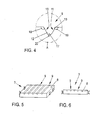
- the light guide 8 may have various shapes. It may be plate-shaped, rod-shaped or disc-shaped. In FIG. 5 an elongate plate-shaped light guide body 8 is shown in which light is coupled via two opposite end faces each light of two light sources.
- the light extraction structures 9 are formed in this case of elongated notches, which extend parallel to the light input surfaces.
- FIG. 6 a rod-shaped light guide body 8 is shown in which the light of a light source is coupled in each case on opposite end faces.
- the Lichtauskoppel Genten 9 are in this case also notches, which are aligned parallel to the Lichteinkoppel lake.
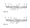
- the supply of the light emitted by the light source 4 to the light guide 8 is effected by a first or second light guide 21, 22, that is, the light emitted from the light source 4 either coupled into the first light guide 21 or in the second light guide 22 and then passed over a first or a second section 23, 24 to the light coupling surfaces of the light guide 8.
- the light emitted by the light source 4 is either according to Fig. 7a the first optical fiber 21 or according to Fig. 7b the second optical fiber 22 is supplied.
- the vehicle lamp 3 has a first panel 25 and a second panel 26, which are arranged to be movable so as to enable or block the coupling of light into the first and second optical fibers 21, 22.
- the apertures 25, 26 there is one of the apertures 25, 26 in the light-transmitting position and the other aperture 25, 26 in the position blocking the light transmission.
- the first aperture 25 is in the light-transmitting position, so that the light emitted by the light source 4 is coupled into the first light guide 21 and then into the light guide 8.
- the second diaphragm 26 is located in the position blocking the passage of light, so that the second diaphragm 26 covers the end surface or the light coupling surface of the second optical fiber 22.
- the light coupling takes place in the second light guide 22 and the light coupling into the first light guide 21 is blocked.
- a masking element 27 is arranged, so that the apertures 25, 26, the light source 4 and the light guides 21, 22 from the vehicle interior are not visible or hidden by the masking element 27.
- both diaphragms 25, 26 are in the light-transmitting position.
- the decoupling surface 16 is used in common for the two light emissions with the different emission characteristics.
- a further variant of the supply of the light emitted by the light source 4 to the light guide 8 is shown.
- a light deflection element 28 is arranged between the light source 4 and the light guide body 8.
- the light deflection element 28 is preferably a mirror or a reflector.
- To produce in the Fig. 2 shown Lichtabstrahl characterizing is according to Fig. 8a moves the light deflecting element 28 into a position such that the light emitted by the light source 4 is reflected by the light deflecting element 28 and conducted to a light guide 29. The light is then fed to the first light coupling surface 6 through the light guide 29 in the light guide 8. In this position of the light deflection element 28, no light reaches the second light coupling surface 7 of the light guide 8.
- the light deflection element 28 is arranged such that the light emitted by the light source 4 is coupled into the second light coupling surface 7 of the light guide body 8.
- the in the Fig. 3 produced Lichtabstrahl characterizing generated.
- the light emitted by the light source 4 does not reach the light guide 29 in this position of the light deflection element 28.
- the light sources 4, 5, 6 may be individual light sources, for example individual light-emitting diodes.
- a light source in the sense of the invention also means the interconnection of a plurality of individual light-emitting elements, for example light-emitting diodes, to form an array or a matrix.
- the plurality of light-emitting elements are arranged on a common chip or a common printed circuit board.
Abstract
Description
- Die vorliegende Erfindung betrifft eine Fahrzeugleuchte, insbesondere zur Beleuchtung des Innenraums des Fahrzeugs. Die Fahrzeugleuchte umfasst zumindest zwei Lichtquellen und einen Lichtleitkörper, der zumindest eine erste Lichteinkoppelfläche zur Einkoppelung der Lichtemission der ersten Lichtquelle, eine zweite Lichteinkoppelfläche zur Einkoppelung der Lichtemission der zweiten Lichtquelle und eine Vielzahl von Lichtauskoppelstrukturen aufweist, bei denen das eingekoppelte Licht reflektiert wird, um bei einer Lichtauskoppelfläche aus dem Lichtleitkörper auszutreten. Des Weiteren umfasst die Fahrzeugleuchte zumindest eine Lichtquelle und einem Lichtleitkörper, der zumindest eine erste Lichteinkoppelfläche zur Einkoppelung der Lichtemission der mindestens einen Lichtquelle, eine zweite Lichteinkoppelfläche zur Einkoppelung der Lichtemission der mindestens einen Lichtquelle und eine Vielzahl von Lichtauskoppelstrukturen aufweist, bei denen das eingekoppelte Licht reflektiert wird, um bei einer Lichtauskoppelfläche aus dem Lichtleitkörper auszutreten.
- Aus der
DE 10 2008 034 052 A1 ist ein Lichtleitkörper bekannt, der insbesondere bei einem Positionslicht oder Tagfahrlicht eines Kraftfahrzeugs eingesetzt werden kann. Mittels des Lichtleitkörpers soll über der Länge des Lichtleitkörpers eine homogene und farbverschiebungsfreie Lichtauskoppelung ermöglicht werden. Zur Einspeisung des Lichts in den Lichtleitkörper sind bei gegenüberliegenden Endflächen des Lichtleitkörpers zwei Lichtquellen vorgesehen, deren Lichtemission eingekoppelt wird. Auf einer Fläche des Lichtleitkörpers sind Prismen zur Lichtauskoppelung über eine gegenüberliegende Lichtauskoppelfläche vorgesehen. Der Lichtleitkörper dient zur Aussendung von Licht in Fahrtrichtung, wobei insgesamt eine homogene Lichtverteilung über der gesamten Länge des Lichtleiters erreicht werden soll, unabhängig davon, ob Licht der ersten oder zweiten Lichtquelle ausgekoppelt wird. - Ferner beschreibt die
DE 10 2005 019 018 A1 eine Leuchte mit einem Lichtleiter und mehreren Lichtquellen, wobei der Lichtleiter voneinander beabstandete Lichteintrittsflächen für von den Lichtquellen ausgestrahltes Licht aufweist. Gegenüberliegend der Lichteintrittsflächen sind jeweils Lichtaustrittsflächen angeordnet, die jeweils in unterschiedliche Richtungen weisen. Bei den Lichtaustrittsflächen tritt das Licht durch die Fläche durch und aus dem Lichtleiter aus. Die Lichtquellen sind als Leuchtdioden ausgebildet, wobei die Leuchtdioden, welche der einen Lichteintrittsfläche zugeordnet sind, weißes Licht emittieren und die Leuchtdioden, welche der anderen Lichteintrittsfläche zugeordnet sind, gelbes Licht emittieren. Auf diese Weise wird erreicht, dass von der Leuchte in einer Richtung weißes Licht abgestrahlt wird und in einer anderen Richtung gelbes Licht. - Bei Fahrzeugen ist der Bauraum sowohl für die Außenleuchten, als auch für die Leuchten, welche Licht in den Innenraum des Fahrzeugs emittieren, sehr begrenzt. Es besteht daher ein Bedürfnis, Fahrzeugleuchten zu schaffen, deren Bauraumbedarf so gering wie möglich ist. Ferner ist es von Vorteil, wenn verschiedene Funktionen der Fahrzeugleuchten in einer Leuchte zusammengefasst werden können.
- Es ist daher die Aufgabe der vorliegenden Erfindung, eine Fahrzeugleuchte bereitzustellen, deren Bauraumbedarf gering ist und die verschiedenen Lichtfunktionen bereitstellen kann.
- Erfindungsgemäß wird diese Aufgabe durch einen Fahrzeugleuchte mit den Merkmalen des Anspruchs 1 oder 2 gelöst. Bevorzugte Weiterbildungen und Ausgestaltungen ergeben sich aus den abhängigen Ansprüchen.
- Die erfindungsgemäße Fahrzeugleuchte ist dadurch gekennzeichnet, dass jede Lichtauskoppelstruktur einen ersten Bereich aufweist, auf den bei eingeschalteter erster Lichtquelle ein Teil der Lichtemission dieser ersten Lichtquelle trifft, und einen zweiten Bereich aufweist, auf den bei eingeschalteter zweiter Lichtquelle ein Teil der Lichtemission dieser zweiten Lichtquelle trifft. Dabei weist die mittels des ersten Bereichs erzeugte Lichtauskoppelung eine andere Abstrahlcharakteristik auf, als die mittels des zweiten Bereichs erzeugte Lichtauskoppelung.
- Die erfindungsgemäße Fahrzeugleuchte ist ferner dadurch gekennzeichnet, dass jede Lichtauskoppelstruktur einen ersten Bereich aufweist, auf den ein Teil der Lichtemission des über die erste Lichteinkoppelfläche in den Lichtleitkörper eingekoppelten Lichts trifft, und einen zweiten Bereich aufweist, auf den ein Teil der Lichtemission des über die zweite Lichteinkoppelfläche in den Lichtleitkörper eingekoppelten Lichts trifft, und dass die mittels des ersten Bereichs erzeugte Lichtauskoppelung eine andere Abstrahlcharakteristik aufweist, als die mittels des zweiten Bereichs erzeugte Lichtauskoppelung.
- Die erfindungsgemäße Fahrzeugleuchte besitzt den Vorteil, dass sie einen sehr geringen Bauraumbedarf hat, wobei gleichzeitig zwei verschiedene Lichtfunktionen bereitgestellt werden können. Da jede einzelne Lichtauskoppelstruktur der Vielzahl von Lichtauskoppelstrukturen eine Lichtauskoppelung mit unterschiedlichen Abstrahlcharakteristiken bewirkt, kann eine Mehrfachfunktion über die gesamte Auskoppelfläche des Lichtleitkörpers bereitgestellt werden. Der Lichtleitkörper ist somit nicht in verschiedene Bereiche unterteilt, die unterschiedliche Abstrahlcharakteristiken bereitstellen. Es werden vielmehr beide Abstrahlcharakteristiken von dem gesamten Lichtleitkörper bereitgestellt. Hierdurch kann die nutzbare Fläche des Lichtleitkörpers erhöht werden, wodurch andererseits der Bauraumbedarf verringert wird.
- Unter einem Lichtleitkörper im Sinne der vorliegenden Erfindung wird ein Körper verstanden, in welchem ein über die Lichteinkoppelfläche eintretender Lichtstrahl zumindest einmal durch Totalreflexion reflektiert wird. Bei dem Lichtleitkörper kann es sich somit beispielsweise um einen Lichtleiter handeln, welcher zwei Lichteinkoppelflächen, z.B. bei gegenüberliegenden Stirnflächen, aufweist.
- Die Anordnung der Lichteinkoppelflächen, der zugeordneten Lichtquellen sowie der beiden Bereiche der Lichtauskoppelstrukturen sind insbesondere so gewählt, dass auf den ersten Bereich nur von der ersten Lichtquelle emittierte Lichtstrahlen treffen und auf den zweiten Bereich nur von der zweiten Lichtquelle emittierte Lichtstrahlen treffen. Auf diese Weise kann eine sehr selektive Lichtauskoppelung erzeugt werden, bei welcher der erste Bereich nur die Abstrahlcharakteristik des Lichts beeinflusst, welches von der ersten Lichtquelle eingekoppelt wurde, und der zweite Bereich nur die Abstrahlcharakteristik des Lichts beeinflusst, welches ursprünglich von der zweiten Lichtquelle eingekoppelt wurde.
- Die Auskoppelfläche des Lichtleitkörpers Ist insbesondere gegenüberliegend zu den Lichtauskoppelstrukturen angeordnet Hierdurch erreicht man vorteilhafterweise, dass die für die Lichtauskoppelung verantwortlichen Strukturen für den Betrachter nicht direkt sichtbar sind. Es kann vielmehr eine glatte Auskoppelfläche bereitgestellt werden, über welche jedoch Licht verschiedener Abstrahlcharakteristiken ausgekoppelt wird.
- Gemäß einer Ausgestaltung der erfindungsgemäßen Fahrzeugleuchte ist die Lichtauskoppelstruktur ein Einschnitt oder eine Kerbe. Der Lichtleitkörper weist somit eine Vielzahl von Einschnitten oder Kerben auf. Hierdurch erreicht man, dass der Lichtleitkörper sehr einfach und kostengünstig gefertigt werden kann. Alternativ kann die Lichtauskoppelstruktur auch von einem Vorsprung oder einer Hervorhebung gebildet sein.
- Gemäß einer Ausgestaltung der erfindungsgemäßen Fahrzeugleuchte sind die beiden Bereiche der Lichtauskoppelstruktur zwei Flächen, die einen Winkel einschließen. Dabei kann eine der Flächen eben sein. Eine andere Fläche kann gekrümmt sein. Auf diese Weise kann man auf einfache und kostengünstige Weise die unterschiedliche Abstrahlcharakteristik erzeugen.
- Gemäß einer weiteren Ausgestaltung der erfindungsgemäßen Fahrzeugleuchte ist die von dem ersten Bereich erzeugte Abstrahlcharakteristik ein gerichtetes Lichtbündel. Das Lichtbündel kann beispielsweise einen Öffnungswinkel von kleiner als 15°, insbesondere kleiner als 10° und bevorzugt kleiner als 5° aufweisen. Hierdurch kann vorteilhafterweise ein Leselicht im Innenraum des Fahrzeugs bereitgestellt werden.
- Gemäß einer weiteren Ausgestaltung der erfindungsgemäßen Fahrzeugleuchte ist die von dem zweiten Bereich erzeugte Abstrahlcharakteristik eine diffuse Lichtemission. Hierfür kann beispielsweise die dem zweiten Bereich zugeordnete Fläche der Lichtauskoppelstruktur eine raue Oberfläche besitzen. Durch die diffuse Lichtemission kann vorteilhafterweise ein großer Bereich des Innenraums des Fahrzeugs ausgeleuchtet werden. Ferner kann eine sogenannte Ambientebeleuchtung bereitgestellt werden.
- Unter einer diffusen Lichtabstrahlung wird im Sinne der Erfindung verstanden, dass die Lichtemission nicht gerichtet ist, sondern aufgrund einer Vielzahl von Streuzentren in eine Vielzahl von unterschiedlichen Richtungen erfolgt. Anders als bei Linsenelementen, die parallele, konvergierende oder divergierende Lichtbündel erzeugen, d.h. eine gerichtete Lichtemission, ist die Lichtemission bei der diffusen Lichtabstrahlung nicht gerichtet. Beispielsweise kann ein parallel auftreffendes Lichtbündel gemäß dem Lambertschen Gesetz reflektiert werden oder eine Großwinkelstreuung erzeugt werden.
- Alternativ kann von dem zweiten Bereich auch eine Abstrahlcharakteristik mit einem stark divergenten Lichtbündel erzeugt werden. Der Öffnungswinkel der Lichtemission kann beispielsweise größer als 50°, insbesondere größer als 60° sein.
- Der Lichtleitkörper kann plattenförmig, stabförmig oder scheibenförmig sein. Auf diese Weise lässt sich die Fahrzeugleuchte flexibel an verschiedene Einbausituationen insbesondere im Innenraum des Fahrzeugs anpassen.
- Die Erfindung wird nun anhand von Ausführungsbeispielen mit Bezug zu den Zeichnungen erläutert.
- Figur 1
- zeigt schematisch ein Fahrzeug mit einem Ausführungsbeispiel der erfindungsgemäßen Fahrzeugleuchte.
- Figur 2
- zeigt einen Schnitt durch ein Ausführungsbeispiel der erfindungsgemäßen Fahrzeugleuchte mit dem Strahlengang einer ersten Lichtquelle,
- Figur 3
- zeigt einen Schnitt durch das Ausführungsbeispiel der erfindungsgemäßen Fahrzeugleuchte mit dem Strahlengang einer zweiten Lichtquelle,
- Figur 4
- zeigt eine Detailansicht der
Figur 2 , - Figur 5
- zeigt ein Beispiel eines Lichtleitkörpers eines Ausführungsbeispiels der erfindungsgemäßen Fahrzeugleuchte,
- Figur 6
- zeigt ein anderes Beispiel eines Lichtleitkörpers eines Ausführungsbeispiels der erfindungsgemäßen Fahrzeugleuchte
- Figuren 7a, 7b
- zeigen ein anderes Beispiel einer Lichteinkopplung in einen Lichtleitkörper eines Ausführungsbeispiels der erfindungsgemäßen Fahrzeugleuchte und
- Figuren 8a, 8b
- zeigen ein weiteres Beispiel einer Lichteinkopplung in einen Lichtleitkörper eines Ausführungsbeispiels der erfindungsgemäßen Fahrzeugleuchte.
- In
Figur 1 ist ein Fahrzeug 1 dargestellt, bei welchem ein Ausführungsbeispiel der erfindungsgemäßen Fahrzeugleuchte 3 im Bereich der Decke bzw. des Dachhimmels im Innenraum 2 des Fahrzeugs 1 angeordnet ist. Die Leuchte 3 stellt dort zum einen eine Leseleuchte und zum anderen eine allgemeine Beleuchtung des Innenraums 2 des Fahrzeugs 1 bereit. - Wie in den
Figuren 2 und 3 gezeigt, umfasst die Fahrzeugleuchte zwei Lichtquellen 4 und 5. InFigur 2 ist der Fall dargestellt, bei dem die Lichtquelle 4 eingeschaltet ist, InFigur 3 ist der Fall dargestellt, bei dem die gegenüberliegend angeordnete Lichtquelle 5 eingeschaltet ist. Die Fahrzeugleuchte 3 umfasst einen Lichtleitkörper 8 mit einer ersten Lichteinkoppelfläche 6, bei welcher die Lichtemission der Lichtquelle 4 eingekoppelt wird, und eine zweite Lichteinkoppelfläche 7, bei welcher die Lichtemission der Lichtquelle 5 eingekoppelt wird. Die Lichteinkoppelflächen 6 und 7 sind auf abgewandten Enden des Lichtleitkörpers 8 angeordnet. Das über die beiden Lichteinkoppelflächen 6 und 7 eingekoppelte Licht der Lichtquellen 4 und 5 wird in dem Lichtleitkörper 8 durch Totalreflexion geleitet, sodass es sich in dem gesamten Lichtleitkörper 8 verteilt. - Zur Auskoppelung des Lichts in dem Lichtleitkörper 8 ist eine Vielzahl von Lichtauskoppelstrukturen 9 vorgesehen. Eine Lichtauskoppelstruktur 9 ist in der Detailansicht A der
Figur 4 dargestellt. Die Lichtauskoppelstruktur 9 ist in diesem Fall von einem Einschnitt bzw. einer Kerbe gebildet. Die Kerbe weist einen ersten Bereich 10 auf, auf den nur Licht auftritt, das ursprünglich von der Lichtquelle 4 emittiert wurde. Ferner weist die Kerbe einen zweiten Bereich 11 auf, auf den nur Licht trifft, welches von der Lichtquelle 5 emittiert wurde. Der Lichtweg 14 der von der Lichtquelle 4 emittierten Lichtstrahlen, die über die erste Lichteinkoppelfläche 6 in den Lichtleitkörper 8 eingekoppelt werden und die auf den ersten Bereich 10 der Lichtauskoppelstrukturen 9 auftreffen, ist inFigur 2 gezeigt. Der Lichtweg 15 der von der Lichtquelle 5 emittierten Lichtstrahlen, die über die zweite Lichteinkoppelfläche 7 in den Lichtleitkörper 8 eingekoppelt werden und die auf den zweiten Bereich 11 der Lichtauskoppelstrukturen 9 auftreffen, ist inFigur 3 gezeigt. - Bei dem ersten Bereich 10 der Lichtauskoppelstrukturen 9 ist eine ebene Fläche gebildet, welche den Winkel 18 mit einer Oberfläche des Lichtleitkörpers 8 einschließt. Bei dieser Fläche 12 werden die auftreffenden Lichtstrahlen reflektiert. Hierfür kann die Fläche 12 ggf. mit einer entsprechenden Beschichtung versehen sein. Nach der Reflektion an der Fläche 12 gelangen die Lichtstrahlen zu der gegenüberliegenden Auskoppelfläche 16 des Lichtleitkörpers 8, bei welcher sie aus dem Lichtleitkörper 8 austreten.
- Bei dem zweiten Bereich 11 der Lichtauskoppelstrukturen 9 ist auch eine Fläche 13 gebildet, die jedoch gekrümmt ist. Sie schließt einen Winkel 19 mit der Oberfläche des Lichtleitkörpers 8 ein. Bei den Winkeln 18 und 19 handelt es sich insbesondere um stumpfe Winkel. Die gekrümmte Fläche 13 trifft bei einer Verbindungslinie 20 auf das Ende der ebenen Fläche 12. Die beiden Flächen schließen den spitzen Winkel 17 ein. Das auf die Fläche 13 vom Inneren des Lichtleitkörpers 8 auftreffende Licht wird auch reflektiert. Hierzu kann auch die Fläche 13 mit einer entsprechenden Beschichtung versehen sein. Nach der Reflexion an der Fläche 13 tritt das Licht bei der gegenüberliegenden Lichtauskoppelfläche 16 aus dem Lichtleitkörper 8 aus.
- Die Fläche 12 ist relativ zu der ersten Lichteinkoppelfläche 6 und der Lichtquelle 4 so angeordnet und ausgerichtet, dass die Abstrahlcharakteristik des bei dieser Fläche 12 reflektierten Lichts beim Austritt aus der Auskoppelfläche 16 einen sehr kleinen Öffnungswinkel besitzt, der z.B. in einem Bereich zwischen 15° und 5° liegt. Es wird somit ein Spot bereitgestellt, welcher als Leselicht dient.
- Im Gegensatz hierzu ist die Anordnung und Krümmung der Fläche 13 relativ zu der zweiten Lichteinkoppelfläche 7 und der Lichtquelle 5 so ausgebildet und angeordnet, dass eine andere Abstrahlcharakteristik erzeugt wird, nämlich eine Lichtemission mit einem sehr großen Öffnungswinkel. Der Öffnungswinkel ist insbesondere größer als 50°, bevorzugt größer als 60°. Die verschiedenen Abstrahlcharakteristiken sind in den
Figuren 2 und 3 gezeigt. Des Weiteren kann die Fläche 13 rau ausgebildet sein, sodass eine Vielzahl von Streuzentren bereitgestellt wird, sodass bei der Reflektion an dieser Fläche 13 eine diffuse Abstrahlcharakteristik erzeugt wird. Es wird somit insbesondere keine gerichtete Lichtemission erzeugt. - Bei den Lichtquellen 4 und 5 der erfindungsgemäßen Fahrzeugleuchte handelt es sich insbesondere um lichtemittierende Dioden. Die Verwendung von lichtemittierenden Dioden hat den Vorteil, dass diese Lichtquellen einen sehr geringen Bauraumbedarf und eine hohe Lebensdauer haben.
- Die Lichtquellen 4 und 5 können getrennt beispielsweise über einen Kippschalter angesteuert werden, sodass nur eine der beiden Lichtquellen 4 und 5 eingeschaltet ist oder beide Lichtquellen 4 und 5 gemeinsam eingeschaltet sind. Dabei ergibt sich, dass auch wenn nur eine der Lichtquellen 4 und 5 eingeschaltet ist, jeweils die gesamte Auskoppelfläche 16 für die Lichtabstrahlung der Fahrzeugleuchte genutzt wird. Wenn beide Lichtquellen 4, 5 eingeschaltet sind, wird die Auskoppelfläche 16 gemeinsam für die beiden Lichtemissionen mit den verschiedenen Abstrahlcharakteristiken genutzt Jede Auskoppelstruktur 9 kann somit zu einer Lichtauskoppelung der Lichtemission der Lichtquelle 4 und der Lichtemission der Lichtquelle 5 beitragen.
- Der Lichtleitkörper 8 kann verschiedene Formen haben. Er kann plattenförmig, stabförmig oder scheibenförmig sein. In
Figur 5 ist ein länglicher plattenförmiger Lichtleitkörper 8 gezeigt, bei dem über zwei abgewandte Stirnflächen jeweils Licht zweier Lichtquellen eingekoppelt wird. Die Lichtauskoppelstrukturen 9 sind in diesem Fall von länglichen Kerben gebildet, die sich parallel zu den Lichteinkoppelflächen erstrecken. - In
Figur 6 ist ein stabförmiger Lichtleitkörper 8 gezeigt, bei dem auf abgewandten Stirnflächen jeweils das Licht einer Lichtquelle eingekoppelt wird. Die Lichtauskoppelstrukturen 9 sind in diesem Fall auch Kerben, die parallel zu den Lichteinkoppelflächen ausgerichtet sind. - Gemäß einem weiteren in den
Figuren 7a, 7b gezeigten Ausführungsbeispiel erfolgt die Erzeugung der beiden verschiedene Abstrahlcharakteristiken aufweisenden Lichtfunktionen mittels einer Lichtquelle 4. Die Zuführung des durch die Lichtquelle 4 emittierten Lichts zu dem Lichtleitkörper 8 erfolgt durch einen ersten bzw. zweiten Lichtleiter 21, 22, d.h. das von der Lichtquelle 4 emittierte Licht wird entweder in den ersten Lichtleiter 21 oder in den zweiten Lichtleiter 22 eingekoppelt und anschließend über einen ersten bzw. einen zweiten Abschnitt 23, 24 zu den Lichteinkoppelflächen des Lichtleitkörpers 8 geleitet. Bevorzugt wird das von der Lichtquelle 4 emittierte Licht entweder gemäßFig. 7a dem ersten Lichtleiter 21 oder gemäßFig. 7b dem zweiten Lichtleiter 22 zugeführt. Hierzu weist die Fahrzeugleuchte 3 eine erste Blende 25 und eine zweite Blende 26 auf, die derart bewegbar angeordnet sind, dass sie die Lichteinkopplung in den ersten bzw. zweiten Lichtleiter 21, 22 ermöglichen oder blockieren. Abhängig davon welche Abstrahlcharakteristik erzeugt werden soll, befindet sich eine der Blenden 25, 26 in der lichtdurchlassenden Stellung und die andere Blende 25, 26 in der den Lichtdurchlass sperrenden Position. In dem inFig. 7a gezeigten Bespiel befindet sich die erste Blende 25 in der lichtdurchlassenden Stellung, so dass das von der Lichtquelle 4 emittierte Licht in den ersten Lichtleiter 21 und anschließend in den Lichtleitkörper 8 eingekoppelt wird. Die zweite Blende 26 befindet sich in der den Lichtdurchlass sperrenden Position, so dass die zweite Blende 26 die Stirnfläche bzw. die Lichteinkoppelfläche des zweiten Lichtleiters 22 abdeckt. Hierdurch wird das von der Lichtquelle 4 emittierte Licht nicht in den zweiten Lichtleiter 22 eingekoppelt. GemäßFig. 7b erfolgt die Lichteinkopplung in den zweiten Lichtleiter 22 und die Lichteinkopplung in den ersten Lichtleiter 21 ist blockiert. - Oberhalb des Lichtleitkörpers 8 ist ein Maskierelement 27 angeordnet, so dass die Blenden 25, 26, die Lichtquelle 4 und die Lichtleiter 21, 22 vom Fahrzeuginnenraum her nicht sichtbar bzw. verdeckt durch das Maskierelement 27 angeordnet sind.
- Alternativ ist es auch denkbar, dass sich beide Blenden 25, 26 in der lichtdurchlassenden Stellung befinden. Somit wird die Auskoppelfläche 16 gemeinsam für die beiden Lichtemissionen mit den verschiedenen Abstrahlcharakteristiken genutzt.
- Anstatt der Verwendung der ersten und zweiten Blende 25, 26 ist es auch denkbar, die Lichtquelle 4 derart zu schwenken, dass das von ihr emittierte Licht entweder in den ersten Lichtleiter 21 oder in den zweiten Lichtleiter 22 eingekoppelt wird.
- In den
Fig. 8a, 8b ist eine weitere Variante der Zuführung des durch die Lichtquelle 4 emittierten Lichts zu dem Lichtleitkörper 8 gezeigt. Hierbei ist ein Lichtumlenkelement 28 zwischen der Lichtquelle 4 und dem Lichtleitkörper 8 angeordnet. Bei dem Lichtumlenkelement 28 handelt es sich bevorzugt um einen Spiegel oder einen Reflektor. Zur Erzeugung der in derFig. 2 gezeigten Lichtabstrahlcharakteristik wird gemäßFig. 8a das Lichtumlenkelement 28 in eine Position bewegt, so dass das von der Lichtquelle 4 emittierte Licht an dem Lichtumlenkelement 28 reflektiert und zu einem Lichtleiter 29 geleitet wird. Das Licht wird dann an der ersten Lichteinkoppelfläche 6 durch den Lichtleiter 29 in den Lichtleitkörper 8 eingespeist. In dieser Position des Lichtumlenkelementes 28 gelangt kein Licht zu der zweiten Lichteinkoppelfläche 7 des Lichtleitkörpers 8. - Gemäß
Fig. 8b ist das Lichtumlenkelement 28 derart angeordnet, dass das von der Lichtquelle 4 emittierte Licht in die zweite Lichteinkoppelfläche 7 des Lichtleitkörpers 8 eingekoppelt wird. Hierdurch wird die in derFig. 3 gezeigte Lichtabstrahlcharakteristik erzeugt. Das von der Lichtquelle 4 emittierte Licht gelangt in dieser Position des Lichtumlenkelementes 28 nicht zum Lichtleiter 29. - Bei den Lichtquellen 4, 5, 6 kann es sich um einzelne Lichtquellen, beispielsweise einzelne lichtemittierenden Dioden handeln. Unter einer Lichtquelle im Sinne der Erfindung wird auch die Zusammenschaltung mehrerer einzelner lichtemittierender Elemente, beispielsweise lichtemittierender Dioden, zu einem Array bzw. einer Matrix verstanden. Insbesondere sind die mehreren lichtemittierenden Elemente auf einem gemeinsamen Chip bzw. einer gemeinsamen Leiterplatine angeordnet.
-
- 1
- Fahrzeug
- 2
- Innenraum des Fahrzeugs
- 3
- Fahrzeugleuchte
- 4
- Lichtquelle
- 5
- Lichtquelle
- 6
- erste Lichteinkoppelfläche
- 7
- zweite Lichteinkoppelfläche
- 8
- Lichtleitkörper
- 9
- Lichtauskoppelstrukturen
- 10
- erster Bereich
- 11
- zweiter Bereich
- 12
- Fläche
- 13
- Fläche
- 14
- Lichtweg
- 15
- Lichtweg
- 16
- Auskoppelfläche
- 17
- Winkel
- 18
- Winkel
- 19
- Winkel
- 20
- Verbindungslinie
- 21
- erster Lichtleiter
- 22
- zweiter Lichtleiter
- 23
- erster Abschnitt
- 24
- zweiter Abschnitt
- 25
- erste Blende
- 26
- zweite Blende
- 27
- Maskierelement
- 28
- Lichtumlenkelement
- 29
- dritter Lichtleiter
Claims (10)
- Fahrzeugleuchte (3), insbesondere zur Beleuchtung des Innenraums (2) des Fahrzeugs (1), mit- zumindest zwei Lichtquellen (4,5) und- einem Lichtleitkörper (8), der zumindest eine erste Lichteinkoppelfläche (6) zur Einkoppelung der Lichtemission der ersten Lichtquelle (4), eine zweite Lichteinkoppelfläche (7) zur Einkoppelung der Lichtemission der zweiten Lichtquelle (5) und eine Vielzahl von Lichtauskoppelstrukturen (9) aufweist, bei denen das eingekoppelte Licht reflektiert wird, um bei einer Lichtauskoppelfläche (16) aus dem Lichtleitkörper (8) auszutreten,
dadurch gekennzeichnet,- dass jede Lichtauskoppelstruktur (9) einen ersten Bereich (10) aufweist, auf den bei eingeschalteter erster Lichtquelle (4) ein Teil der Lichtemission dieser ersten Lichtquelle (4) trifft, und einen zweiten Bereich (11) aufweist, auf den bei eingeschalteter zweiter Lichtquelle (5) ein Teil der Lichtemission dieser zweiten Lichtquelle (5) trifft, und- dass die mittels des ersten Bereichs (10) erzeugte Lichtauskoppelung eine andere Abstrahlcharakteristik aufweist, als die mittels des zweiten Bereichs (11) erzeugte Lichtauskoppelung. - Fahrzeugleuchte (3), insbesondere zur Beleuchtung des Innenraums (2) des Fahrzeugs (1), mit- zumindest einer Lichtquelle (4) und- einem Lichtleitkörper (8), der zumindest eine erste Lichteinkoppelfläche (6) zur Einkoppelung der Lichtemission der mindestens einen Lichtquelle (4), eine zweite Lichteinkoppelfläche (7) zur Einkoppelung der Lichtemission der mindestens einen Lichtquelle (4) und eine Vielzahl von Lichtauskoppelstrukturen (9) aufweist, bei denen das eingekoppelte Licht reflektiert wird, um bei einer Lichtauskoppelfläche (16) aus dem Lichtleitkörper (8) auszutreten,
dadurch gekennzeichnet,- dass jede Lichtauskoppelstruktur (9) einen ersten Bereich (10) aufweist, auf den ein Teil der Lichtemission des über die erste Lichteinkoppelfläche (6) in den Lichtleitkörper (8) eingekoppelten Lichts trifft, und einen zweiten Bereich (11) aufweist, auf den ein Teil der Lichtemission des über die zweite Lichteinkoppelfläche (7) in den Lichtleitkörper (8) eingekoppelten Lichts trifft, und- dass die mittels des ersten Bereichs (10) erzeugte Lichtauskoppelung eine andere Abstrahlcharakteristik aufweist, als die mittels des zweiten Bereichs (11) erzeugte Lichtauskoppelung. - Fahrzeugleuchte (3) nach Anspruch 1 oder 2,
dadurch gekennzeichnet,
dass die Lichtauskoppelstruktur (9) ein Einschnitt oder eine Kerbe ist. - Fahrzeugleuchte (3) nach einem der vorhergehenden Ansprüche,
dadurch gekennzeichnet,
dass die beiden Bereiche (10,11) der Lichtauskoppelstruktur (9) zwei Flächen (12, 13) sind, die einen Winkel (17) einschließen. - Fahrzeugleuchte (3) nach Anspruch 4,
dadurch gekennzeichnet,
dass zumindest eine der Flächen (12) eben ist. - Fahrzeugleuchte (3) nach Anspruch 4 oder 5,
dadurch gekennzeichnet,
dass zumindest eine der Flächen (13) gekrümmt ist. - Fahrzeugleuchte (3) nach einem der vorhergehenden Ansprüche,
dadurch gekennzeichnet,
dass die von dem ersten Bereich (10) erzeugte Abstrahlcharakteristik ein gerichtetes Lichtbündel ist. - Fahrzeugleuchte (3) nach einem der vorhergehenden Ansprüche,
dadurch gekennzeichnet,
dass die von dem zweiten Bereich (11) erzeugte Abstrahlcharakteristik eine diffuse Lichtemission ist. - Fahrzeugleuchte (3) nach einem der Ansprüche 4 bis 8,
dadurch gekennzeichnet,
dass zumindest eine der Flächen (13) eine raue Oberfläche besitzt. - Fahrzeugleuchte (3) nach einem der vorhergehenden Ansprüche,
dadurch gekennzeichnet,
dass der Lichtleitkörper (8) plattenförmig, stabförmig oder scheibenförmig ist.
Applications Claiming Priority (1)
| Application Number | Priority Date | Filing Date | Title |
|---|---|---|---|
| DE102011014919A DE102011014919A1 (de) | 2011-03-24 | 2011-03-24 | Fahrzeugleuchte, insbesondere zur Beleuchtung des Innenraums des Fahrzeugs |
Publications (2)
| Publication Number | Publication Date |
|---|---|
| EP2502784A1 true EP2502784A1 (de) | 2012-09-26 |
| EP2502784B1 EP2502784B1 (de) | 2019-06-26 |
Family
ID=45954278
Family Applications (1)
| Application Number | Title | Priority Date | Filing Date |
|---|---|---|---|
| EP12001791.8A Active EP2502784B1 (de) | 2011-03-24 | 2012-03-16 | Fahrzeugleuchte, insbesondere zur Beleuchtung des Innenraums des Fahrzeugs |
Country Status (2)
| Country | Link |
|---|---|
| EP (1) | EP2502784B1 (de) |
| DE (1) | DE102011014919A1 (de) |
Cited By (3)
| Publication number | Priority date | Publication date | Assignee | Title |
|---|---|---|---|---|
| WO2014105470A1 (en) * | 2012-12-28 | 2014-07-03 | 3M Innovative Properties Company | Multifunction lightguide tailight article |
| GB2489813B (en) * | 2011-04-08 | 2017-11-22 | Gm Global Tech Operations Llc | An illuminating formed part, especially a decorative part and/or a covering part for the interior space of a vehicle |
| CN108602416A (zh) * | 2016-02-01 | 2018-09-28 | 欧文汽车产品有限责任公司 | 发光的汽车遮阳板镜子 |
Families Citing this family (4)
| Publication number | Priority date | Publication date | Assignee | Title |
|---|---|---|---|---|
| DE102012020712A1 (de) * | 2012-10-23 | 2014-04-24 | Volkswagen Aktiengesellschaft | Beleuchtungseinrichtung für ein Fahrzeugteil umfassend einen Lichtleiter und Fahrzeugteil mit einer Beleuchtungseinrichtung |
| DK177763B1 (en) * | 2012-11-26 | 2014-06-16 | Bang & Olufsen As | A compact lens arrangement |
| ES2527971B2 (es) * | 2014-04-07 | 2015-08-13 | Seat, S.A. | Dispositivo de señalización óptica para faro de vehículo |
| DE102016219527B4 (de) * | 2016-10-07 | 2021-07-08 | Audi Ag | Beleuchtungsvorrichtung für einen Innenraum eines Kraftfahrzeugs, Verfahren zum Betreiben einer Beleuchtungsvorrichtung und Kraftfahrzeug mit einer Beleuchtungsvorrichtung |
Citations (5)
| Publication number | Priority date | Publication date | Assignee | Title |
|---|---|---|---|---|
| DE20312518U1 (de) * | 2003-08-13 | 2003-12-24 | Fer Fahrzeugelektrik Gmbh | Fahrzeugleuchte |
| JP2006236588A (ja) * | 2005-02-22 | 2006-09-07 | Koito Mfg Co Ltd | 光照明装置及び車両用灯具 |
| DE102005019018A1 (de) | 2005-04-23 | 2006-10-26 | Volkswagen Ag | Leuchte mit wenigstens einem Lichtleiter und mehreren Lichtquellen |
| EP2071228A2 (de) * | 2007-12-14 | 2009-06-17 | Koito Manufacturing Co., Ltd. | Fahrzeuglampenbaugruppe |
| DE102008034052A1 (de) | 2008-07-22 | 2010-01-28 | Hella Kgaa Hueck & Co. | Lichtleitkörper, insbesondere für ein Kraftfahrzeug |
Family Cites Families (4)
| Publication number | Priority date | Publication date | Assignee | Title |
|---|---|---|---|---|
| WO2000050808A1 (en) * | 1999-02-24 | 2000-08-31 | 3M Innovative Properties Company | Illumination device for producing predetermined intensity patterns |
| DE20019073U1 (de) * | 2000-11-09 | 2001-02-22 | Hella Kg Hueck & Co | Beleuchtungseinrichtung |
| DE10314352A1 (de) * | 2003-03-31 | 2004-10-14 | Hella Kg Hueck & Co. | Beleuchtungseinrichtung |
| DE10332158A1 (de) * | 2003-07-15 | 2005-02-03 | Daimlerchrysler Ag | Innenraumleuchte, insbesondere für ein Fahrzeug |
-
2011
- 2011-03-24 DE DE102011014919A patent/DE102011014919A1/de not_active Withdrawn
-
2012
- 2012-03-16 EP EP12001791.8A patent/EP2502784B1/de active Active
Patent Citations (5)
| Publication number | Priority date | Publication date | Assignee | Title |
|---|---|---|---|---|
| DE20312518U1 (de) * | 2003-08-13 | 2003-12-24 | Fer Fahrzeugelektrik Gmbh | Fahrzeugleuchte |
| JP2006236588A (ja) * | 2005-02-22 | 2006-09-07 | Koito Mfg Co Ltd | 光照明装置及び車両用灯具 |
| DE102005019018A1 (de) | 2005-04-23 | 2006-10-26 | Volkswagen Ag | Leuchte mit wenigstens einem Lichtleiter und mehreren Lichtquellen |
| EP2071228A2 (de) * | 2007-12-14 | 2009-06-17 | Koito Manufacturing Co., Ltd. | Fahrzeuglampenbaugruppe |
| DE102008034052A1 (de) | 2008-07-22 | 2010-01-28 | Hella Kgaa Hueck & Co. | Lichtleitkörper, insbesondere für ein Kraftfahrzeug |
Cited By (7)
| Publication number | Priority date | Publication date | Assignee | Title |
|---|---|---|---|---|
| GB2489813B (en) * | 2011-04-08 | 2017-11-22 | Gm Global Tech Operations Llc | An illuminating formed part, especially a decorative part and/or a covering part for the interior space of a vehicle |
| WO2014105470A1 (en) * | 2012-12-28 | 2014-07-03 | 3M Innovative Properties Company | Multifunction lightguide tailight article |
| CN104903642A (zh) * | 2012-12-28 | 2015-09-09 | 3M创新有限公司 | 多功能光导尾灯制品 |
| CN108602416A (zh) * | 2016-02-01 | 2018-09-28 | 欧文汽车产品有限责任公司 | 发光的汽车遮阳板镜子 |
| EP3411251A4 (de) * | 2016-02-01 | 2019-08-07 | Irvin Automotive Products, LLC | Beleuchteter spiegel mit automatischer blende |
| US11077789B2 (en) | 2016-02-01 | 2021-08-03 | Irvin Automotive Products, LLC | Lighted auto visor mirror |
| CN108602416B (zh) * | 2016-02-01 | 2021-10-15 | 欧文汽车产品有限责任公司 | 发光的汽车遮阳板镜子 |
Also Published As
| Publication number | Publication date |
|---|---|
| DE102011014919A1 (de) | 2012-09-27 |
| EP2502784B1 (de) | 2019-06-26 |
Similar Documents
| Publication | Publication Date | Title |
|---|---|---|
| EP2502784B1 (de) | Fahrzeugleuchte, insbesondere zur Beleuchtung des Innenraums des Fahrzeugs | |
| EP2688769B1 (de) | Fahrzeugleuchte zur beleuchtung des innenraums des fahrzeugs | |
| EP2889529B1 (de) | Kraftfahrzeugleuchte mit einem linien- oder flächenhaften Erscheinungsbild | |
| EP2065635B1 (de) | Beleuchtungsvorrichtung für Fahrzeuge | |
| EP1715244B1 (de) | Signalleuchte für Fahrzeuge | |
| EP2354637B1 (de) | Beleuchtungsvorrichtung für Fahrzeuge | |
| DE102012107437B4 (de) | Leuchtvorrichtung | |
| DE102013104174A1 (de) | Beleuchtungsvorrichtung für Fahrzeuge | |
| DE102010061210A1 (de) | Leuchte für Fahrzeuge | |
| EP1886871A1 (de) | Signalleuchte für Fahrzeuge | |
| DE102011002340A1 (de) | Beleuchtungsvorrichtung für Fahrzeuge | |
| EP3190332A1 (de) | Beleuchtungseinheit für ein kraftfahrzeug | |
| EP1898147B1 (de) | Beleuchtungseinrichtung für Fahrzeuge | |
| EP3210827A1 (de) | Leuchte für kraftfahrzeuge | |
| EP3052852A1 (de) | Beleuchtungsvorrichtung für fahrzeuge | |
| DE102015115969A1 (de) | Beleuchtungsvorrichtung für Fahrzeuge | |
| DE102013007856A1 (de) | Lichtleitkörper und Leuchtvorrichtung mit dem Lichtleitkörper | |
| EP1832902A1 (de) | Flache Leuchtvorrichtung | |
| DE102010045052B4 (de) | Beleuchtungseinrichtung für Fahrzeuge mit einem flächigen Lichtleitelement zur Erzeugung einer Seitenmarkierungslichtfunktion und einer Schlusslichtfunktion | |
| DE102017106441A1 (de) | Kraftfahrzeugleuchte mit einem flächigen Lichtleiter | |
| EP3461687B1 (de) | Lichtleiteranordnung einer kraftfahrzeugleuchte und kraftfahrzeugleuchte mit einer solchen lichtleiteranordnung | |
| DE102019118518A1 (de) | Beleuchtungsvorrichtung für Fahrzeuge | |
| DE102008050246A1 (de) | Zierleuchteneinheit für ein Fahrzeug | |
| DE102012213547B4 (de) | Beleuchtungseinrichtung für ein Kraftfahrzeug | |
| DE102016115278B4 (de) | Beleuchtungseinrichtung für ein Kraftfahrzeug |
Legal Events
| Date | Code | Title | Description |
|---|---|---|---|
| PUAI | Public reference made under article 153(3) epc to a published international application that has entered the european phase |
Free format text: ORIGINAL CODE: 0009012 |
|
| AK | Designated contracting states |
Kind code of ref document: A1 Designated state(s): AL AT BE BG CH CY CZ DE DK EE ES FI FR GB GR HR HU IE IS IT LI LT LU LV MC MK MT NL NO PL PT RO RS SE SI SK SM TR |
|
| AX | Request for extension of the european patent |
Extension state: BA ME |
|
| 17P | Request for examination filed |
Effective date: 20130326 |
|
| REG | Reference to a national code |
Ref country code: DE Ref legal event code: R079 Ref document number: 502012014954 Country of ref document: DE Free format text: PREVIOUS MAIN CLASS: B60Q0003000000 Ipc: B60Q0003640000 |
|
| GRAP | Despatch of communication of intention to grant a patent |
Free format text: ORIGINAL CODE: EPIDOSNIGR1 |
|
| STAA | Information on the status of an ep patent application or granted ep patent |
Free format text: STATUS: GRANT OF PATENT IS INTENDED |
|
| RIC1 | Information provided on ipc code assigned before grant |
Ipc: F21S 43/247 20180101ALI20190305BHEP Ipc: F21S 43/249 20180101ALI20190305BHEP Ipc: F21V 8/00 20060101ALI20190305BHEP Ipc: F21Y 101/00 20160101ALN20190305BHEP Ipc: B60Q 3/66 20170101ALI20190305BHEP Ipc: B60Q 3/64 20170101AFI20190305BHEP Ipc: G02B 6/00 20060101ALI20190305BHEP Ipc: F21S 43/245 20180101ALI20190305BHEP |
|
| INTG | Intention to grant announced |
Effective date: 20190327 |
|
| GRAS | Grant fee paid |
Free format text: ORIGINAL CODE: EPIDOSNIGR3 |
|
| GRAA | (expected) grant |
Free format text: ORIGINAL CODE: 0009210 |
|
| STAA | Information on the status of an ep patent application or granted ep patent |
Free format text: STATUS: THE PATENT HAS BEEN GRANTED |
|
| AK | Designated contracting states |
Kind code of ref document: B1 Designated state(s): AL AT BE BG CH CY CZ DE DK EE ES FI FR GB GR HR HU IE IS IT LI LT LU LV MC MK MT NL NO PL PT RO RS SE SI SK SM TR |
|
| REG | Reference to a national code |
Ref country code: GB Ref legal event code: FG4D Free format text: NOT ENGLISH |
|
| REG | Reference to a national code |
Ref country code: CH Ref legal event code: EP |
|
| REG | Reference to a national code |
Ref country code: AT Ref legal event code: REF Ref document number: 1147908 Country of ref document: AT Kind code of ref document: T Effective date: 20190715 |
|
| REG | Reference to a national code |
Ref country code: DE Ref legal event code: R096 Ref document number: 502012014954 Country of ref document: DE |
|
| REG | Reference to a national code |
Ref country code: IE Ref legal event code: FG4D Free format text: LANGUAGE OF EP DOCUMENT: GERMAN |
|
| REG | Reference to a national code |
Ref country code: NL Ref legal event code: MP Effective date: 20190626 |
|
| PG25 | Lapsed in a contracting state [announced via postgrant information from national office to epo] |
Ref country code: HR Free format text: LAPSE BECAUSE OF FAILURE TO SUBMIT A TRANSLATION OF THE DESCRIPTION OR TO PAY THE FEE WITHIN THE PRESCRIBED TIME-LIMIT Effective date: 20190626 Ref country code: FI Free format text: LAPSE BECAUSE OF FAILURE TO SUBMIT A TRANSLATION OF THE DESCRIPTION OR TO PAY THE FEE WITHIN THE PRESCRIBED TIME-LIMIT Effective date: 20190626 Ref country code: LT Free format text: LAPSE BECAUSE OF FAILURE TO SUBMIT A TRANSLATION OF THE DESCRIPTION OR TO PAY THE FEE WITHIN THE PRESCRIBED TIME-LIMIT Effective date: 20190626 Ref country code: NO Free format text: LAPSE BECAUSE OF FAILURE TO SUBMIT A TRANSLATION OF THE DESCRIPTION OR TO PAY THE FEE WITHIN THE PRESCRIBED TIME-LIMIT Effective date: 20190926 Ref country code: AL Free format text: LAPSE BECAUSE OF FAILURE TO SUBMIT A TRANSLATION OF THE DESCRIPTION OR TO PAY THE FEE WITHIN THE PRESCRIBED TIME-LIMIT Effective date: 20190626 Ref country code: SE Free format text: LAPSE BECAUSE OF FAILURE TO SUBMIT A TRANSLATION OF THE DESCRIPTION OR TO PAY THE FEE WITHIN THE PRESCRIBED TIME-LIMIT Effective date: 20190626 |
|
| REG | Reference to a national code |
Ref country code: LT Ref legal event code: MG4D |
|
| PG25 | Lapsed in a contracting state [announced via postgrant information from national office to epo] |
Ref country code: BG Free format text: LAPSE BECAUSE OF FAILURE TO SUBMIT A TRANSLATION OF THE DESCRIPTION OR TO PAY THE FEE WITHIN THE PRESCRIBED TIME-LIMIT Effective date: 20190926 Ref country code: GR Free format text: LAPSE BECAUSE OF FAILURE TO SUBMIT A TRANSLATION OF THE DESCRIPTION OR TO PAY THE FEE WITHIN THE PRESCRIBED TIME-LIMIT Effective date: 20190927 Ref country code: RS Free format text: LAPSE BECAUSE OF FAILURE TO SUBMIT A TRANSLATION OF THE DESCRIPTION OR TO PAY THE FEE WITHIN THE PRESCRIBED TIME-LIMIT Effective date: 20190626 Ref country code: LV Free format text: LAPSE BECAUSE OF FAILURE TO SUBMIT A TRANSLATION OF THE DESCRIPTION OR TO PAY THE FEE WITHIN THE PRESCRIBED TIME-LIMIT Effective date: 20190626 |
|
| PG25 | Lapsed in a contracting state [announced via postgrant information from national office to epo] |
Ref country code: EE Free format text: LAPSE BECAUSE OF FAILURE TO SUBMIT A TRANSLATION OF THE DESCRIPTION OR TO PAY THE FEE WITHIN THE PRESCRIBED TIME-LIMIT Effective date: 20190626 Ref country code: SK Free format text: LAPSE BECAUSE OF FAILURE TO SUBMIT A TRANSLATION OF THE DESCRIPTION OR TO PAY THE FEE WITHIN THE PRESCRIBED TIME-LIMIT Effective date: 20190626 Ref country code: PT Free format text: LAPSE BECAUSE OF FAILURE TO SUBMIT A TRANSLATION OF THE DESCRIPTION OR TO PAY THE FEE WITHIN THE PRESCRIBED TIME-LIMIT Effective date: 20191028 Ref country code: RO Free format text: LAPSE BECAUSE OF FAILURE TO SUBMIT A TRANSLATION OF THE DESCRIPTION OR TO PAY THE FEE WITHIN THE PRESCRIBED TIME-LIMIT Effective date: 20190626 Ref country code: NL Free format text: LAPSE BECAUSE OF FAILURE TO SUBMIT A TRANSLATION OF THE DESCRIPTION OR TO PAY THE FEE WITHIN THE PRESCRIBED TIME-LIMIT Effective date: 20190626 Ref country code: CZ Free format text: LAPSE BECAUSE OF FAILURE TO SUBMIT A TRANSLATION OF THE DESCRIPTION OR TO PAY THE FEE WITHIN THE PRESCRIBED TIME-LIMIT Effective date: 20190626 |
|
| PG25 | Lapsed in a contracting state [announced via postgrant information from national office to epo] |
Ref country code: SM Free format text: LAPSE BECAUSE OF FAILURE TO SUBMIT A TRANSLATION OF THE DESCRIPTION OR TO PAY THE FEE WITHIN THE PRESCRIBED TIME-LIMIT Effective date: 20190626 Ref country code: IS Free format text: LAPSE BECAUSE OF FAILURE TO SUBMIT A TRANSLATION OF THE DESCRIPTION OR TO PAY THE FEE WITHIN THE PRESCRIBED TIME-LIMIT Effective date: 20191026 Ref country code: ES Free format text: LAPSE BECAUSE OF FAILURE TO SUBMIT A TRANSLATION OF THE DESCRIPTION OR TO PAY THE FEE WITHIN THE PRESCRIBED TIME-LIMIT Effective date: 20190626 Ref country code: IT Free format text: LAPSE BECAUSE OF FAILURE TO SUBMIT A TRANSLATION OF THE DESCRIPTION OR TO PAY THE FEE WITHIN THE PRESCRIBED TIME-LIMIT Effective date: 20190626 |
|
| PG25 | Lapsed in a contracting state [announced via postgrant information from national office to epo] |
Ref country code: TR Free format text: LAPSE BECAUSE OF FAILURE TO SUBMIT A TRANSLATION OF THE DESCRIPTION OR TO PAY THE FEE WITHIN THE PRESCRIBED TIME-LIMIT Effective date: 20190626 |
|
| PG25 | Lapsed in a contracting state [announced via postgrant information from national office to epo] |
Ref country code: DK Free format text: LAPSE BECAUSE OF FAILURE TO SUBMIT A TRANSLATION OF THE DESCRIPTION OR TO PAY THE FEE WITHIN THE PRESCRIBED TIME-LIMIT Effective date: 20190626 Ref country code: PL Free format text: LAPSE BECAUSE OF FAILURE TO SUBMIT A TRANSLATION OF THE DESCRIPTION OR TO PAY THE FEE WITHIN THE PRESCRIBED TIME-LIMIT Effective date: 20190626 |
|
| PGFP | Annual fee paid to national office [announced via postgrant information from national office to epo] |
Ref country code: GB Payment date: 20200327 Year of fee payment: 9 |
|
| PG25 | Lapsed in a contracting state [announced via postgrant information from national office to epo] |
Ref country code: IS Free format text: LAPSE BECAUSE OF FAILURE TO SUBMIT A TRANSLATION OF THE DESCRIPTION OR TO PAY THE FEE WITHIN THE PRESCRIBED TIME-LIMIT Effective date: 20200224 |
|
| REG | Reference to a national code |
Ref country code: DE Ref legal event code: R097 Ref document number: 502012014954 Country of ref document: DE |
|
| PLBE | No opposition filed within time limit |
Free format text: ORIGINAL CODE: 0009261 |
|
| STAA | Information on the status of an ep patent application or granted ep patent |
Free format text: STATUS: NO OPPOSITION FILED WITHIN TIME LIMIT |
|
| PG2D | Information on lapse in contracting state deleted |
Ref country code: IS |
|
| 26N | No opposition filed |
Effective date: 20200603 |
|
| PG25 | Lapsed in a contracting state [announced via postgrant information from national office to epo] |
Ref country code: SI Free format text: LAPSE BECAUSE OF FAILURE TO SUBMIT A TRANSLATION OF THE DESCRIPTION OR TO PAY THE FEE WITHIN THE PRESCRIBED TIME-LIMIT Effective date: 20190626 |
|
| PG25 | Lapsed in a contracting state [announced via postgrant information from national office to epo] |
Ref country code: MC Free format text: LAPSE BECAUSE OF FAILURE TO SUBMIT A TRANSLATION OF THE DESCRIPTION OR TO PAY THE FEE WITHIN THE PRESCRIBED TIME-LIMIT Effective date: 20190626 |
|
| REG | Reference to a national code |
Ref country code: CH Ref legal event code: PL |
|
| REG | Reference to a national code |
Ref country code: BE Ref legal event code: MM Effective date: 20200331 |
|
| PG25 | Lapsed in a contracting state [announced via postgrant information from national office to epo] |
Ref country code: LU Free format text: LAPSE BECAUSE OF NON-PAYMENT OF DUE FEES Effective date: 20200316 |
|
| PG25 | Lapsed in a contracting state [announced via postgrant information from national office to epo] |
Ref country code: LI Free format text: LAPSE BECAUSE OF NON-PAYMENT OF DUE FEES Effective date: 20200331 Ref country code: IE Free format text: LAPSE BECAUSE OF NON-PAYMENT OF DUE FEES Effective date: 20200316 Ref country code: CH Free format text: LAPSE BECAUSE OF NON-PAYMENT OF DUE FEES Effective date: 20200331 |
|
| PG25 | Lapsed in a contracting state [announced via postgrant information from national office to epo] |
Ref country code: BE Free format text: LAPSE BECAUSE OF NON-PAYMENT OF DUE FEES Effective date: 20200331 |
|
| REG | Reference to a national code |
Ref country code: AT Ref legal event code: MM01 Ref document number: 1147908 Country of ref document: AT Kind code of ref document: T Effective date: 20200316 |
|
| PG25 | Lapsed in a contracting state [announced via postgrant information from national office to epo] |
Ref country code: AT Free format text: LAPSE BECAUSE OF NON-PAYMENT OF DUE FEES Effective date: 20200316 |
|
| GBPC | Gb: european patent ceased through non-payment of renewal fee |
Effective date: 20210316 |
|
| PG25 | Lapsed in a contracting state [announced via postgrant information from national office to epo] |
Ref country code: GB Free format text: LAPSE BECAUSE OF NON-PAYMENT OF DUE FEES Effective date: 20210316 |
|
| PG25 | Lapsed in a contracting state [announced via postgrant information from national office to epo] |
Ref country code: MT Free format text: LAPSE BECAUSE OF FAILURE TO SUBMIT A TRANSLATION OF THE DESCRIPTION OR TO PAY THE FEE WITHIN THE PRESCRIBED TIME-LIMIT Effective date: 20190626 Ref country code: CY Free format text: LAPSE BECAUSE OF FAILURE TO SUBMIT A TRANSLATION OF THE DESCRIPTION OR TO PAY THE FEE WITHIN THE PRESCRIBED TIME-LIMIT Effective date: 20190626 |
|
| PG25 | Lapsed in a contracting state [announced via postgrant information from national office to epo] |
Ref country code: MK Free format text: LAPSE BECAUSE OF FAILURE TO SUBMIT A TRANSLATION OF THE DESCRIPTION OR TO PAY THE FEE WITHIN THE PRESCRIBED TIME-LIMIT Effective date: 20190626 |
|
| PGFP | Annual fee paid to national office [announced via postgrant information from national office to epo] |
Ref country code: FR Payment date: 20230323 Year of fee payment: 12 |
|
| PGFP | Annual fee paid to national office [announced via postgrant information from national office to epo] |
Ref country code: DE Payment date: 20230331 Year of fee payment: 12 |
|
| P01 | Opt-out of the competence of the unified patent court (upc) registered |
Effective date: 20230523 |