EP2502378B1 - Transmitter and transmission method for broadcasting data in a broadcasting system providing incremental redundancy - Google Patents
Transmitter and transmission method for broadcasting data in a broadcasting system providing incremental redundancy Download PDFInfo
- Publication number
- EP2502378B1 EP2502378B1 EP10765646.4A EP10765646A EP2502378B1 EP 2502378 B1 EP2502378 B1 EP 2502378B1 EP 10765646 A EP10765646 A EP 10765646A EP 2502378 B1 EP2502378 B1 EP 2502378B1
- Authority
- EP
- European Patent Office
- Prior art keywords
- codeword
- auxiliary
- transmitter
- basic
- codeword portion
- Prior art date
- Legal status (The legal status is an assumption and is not a legal conclusion. Google has not performed a legal analysis and makes no representation as to the accuracy of the status listed.)
- Not-in-force
Links
Images


Classifications
-
- H—ELECTRICITY
- H04—ELECTRIC COMMUNICATION TECHNIQUE
- H04L—TRANSMISSION OF DIGITAL INFORMATION, e.g. TELEGRAPHIC COMMUNICATION
- H04L1/00—Arrangements for detecting or preventing errors in the information received
- H04L1/004—Arrangements for detecting or preventing errors in the information received by using forward error control
- H04L1/0041—Arrangements at the transmitter end
-
- H—ELECTRICITY
- H04—ELECTRIC COMMUNICATION TECHNIQUE
- H04L—TRANSMISSION OF DIGITAL INFORMATION, e.g. TELEGRAPHIC COMMUNICATION
- H04L1/00—Arrangements for detecting or preventing errors in the information received
- H04L1/004—Arrangements for detecting or preventing errors in the information received by using forward error control
- H04L1/0056—Systems characterized by the type of code used
- H04L1/0057—Block codes
- H04L1/0058—Block-coded modulation
-
- H—ELECTRICITY
- H04—ELECTRIC COMMUNICATION TECHNIQUE
- H04L—TRANSMISSION OF DIGITAL INFORMATION, e.g. TELEGRAPHIC COMMUNICATION
- H04L1/00—Arrangements for detecting or preventing errors in the information received
- H04L1/004—Arrangements for detecting or preventing errors in the information received by using forward error control
- H04L1/0056—Systems characterized by the type of code used
- H04L1/0071—Use of interleaving
-
- H—ELECTRICITY
- H04—ELECTRIC COMMUNICATION TECHNIQUE
- H04L—TRANSMISSION OF DIGITAL INFORMATION, e.g. TELEGRAPHIC COMMUNICATION
- H04L1/00—Arrangements for detecting or preventing errors in the information received
- H04L1/0078—Avoidance of errors by organising the transmitted data in a format specifically designed to deal with errors, e.g. location
- H04L1/0079—Formats for control data
- H04L1/008—Formats for control data where the control data relates to payload of a different packet
-
- H—ELECTRICITY
- H03—ELECTRONIC CIRCUITRY
- H03M—CODING; DECODING; CODE CONVERSION IN GENERAL
- H03M13/00—Coding, decoding or code conversion, for error detection or error correction; Coding theory basic assumptions; Coding bounds; Error probability evaluation methods; Channel models; Simulation or testing of codes
- H03M13/29—Coding, decoding or code conversion, for error detection or error correction; Coding theory basic assumptions; Coding bounds; Error probability evaluation methods; Channel models; Simulation or testing of codes combining two or more codes or code structures, e.g. product codes, generalised product codes, concatenated codes, inner and outer codes
- H03M13/2906—Coding, decoding or code conversion, for error detection or error correction; Coding theory basic assumptions; Coding bounds; Error probability evaluation methods; Channel models; Simulation or testing of codes combining two or more codes or code structures, e.g. product codes, generalised product codes, concatenated codes, inner and outer codes using block codes
-
- H—ELECTRICITY
- H03—ELECTRONIC CIRCUITRY
- H03M—CODING; DECODING; CODE CONVERSION IN GENERAL
- H03M13/00—Coding, decoding or code conversion, for error detection or error correction; Coding theory basic assumptions; Coding bounds; Error probability evaluation methods; Channel models; Simulation or testing of codes
- H03M13/65—Purpose and implementation aspects
- H03M13/6522—Intended application, e.g. transmission or communication standard
- H03M13/6552—DVB-T2
-
- H—ELECTRICITY
- H04—ELECTRIC COMMUNICATION TECHNIQUE
- H04L—TRANSMISSION OF DIGITAL INFORMATION, e.g. TELEGRAPHIC COMMUNICATION
- H04L1/00—Arrangements for detecting or preventing errors in the information received
- H04L1/004—Arrangements for detecting or preventing errors in the information received by using forward error control
- H04L1/0045—Arrangements at the receiver end
- H04L1/0052—Realisations of complexity reduction techniques, e.g. pipelining or use of look-up tables
- H04L1/0053—Realisations of complexity reduction techniques, e.g. pipelining or use of look-up tables specially adapted for power saving
-
- H—ELECTRICITY
- H04—ELECTRIC COMMUNICATION TECHNIQUE
- H04L—TRANSMISSION OF DIGITAL INFORMATION, e.g. TELEGRAPHIC COMMUNICATION
- H04L1/00—Arrangements for detecting or preventing errors in the information received
- H04L1/004—Arrangements for detecting or preventing errors in the information received by using forward error control
- H04L1/0056—Systems characterized by the type of code used
- H04L1/0061—Error detection codes
-
- H—ELECTRICITY
- H04—ELECTRIC COMMUNICATION TECHNIQUE
- H04L—TRANSMISSION OF DIGITAL INFORMATION, e.g. TELEGRAPHIC COMMUNICATION
- H04L1/00—Arrangements for detecting or preventing errors in the information received
- H04L1/004—Arrangements for detecting or preventing errors in the information received by using forward error control
- H04L1/0072—Error control for data other than payload data, e.g. control data
-
- H—ELECTRICITY
- H04—ELECTRIC COMMUNICATION TECHNIQUE
- H04L—TRANSMISSION OF DIGITAL INFORMATION, e.g. TELEGRAPHIC COMMUNICATION
- H04L1/00—Arrangements for detecting or preventing errors in the information received
- H04L1/0078—Avoidance of errors by organising the transmitted data in a format specifically designed to deal with errors, e.g. location
- H04L1/0083—Formatting with frames or packets; Protocol or part of protocol for error control
-
- H—ELECTRICITY
- H04—ELECTRIC COMMUNICATION TECHNIQUE
- H04L—TRANSMISSION OF DIGITAL INFORMATION, e.g. TELEGRAPHIC COMMUNICATION
- H04L1/00—Arrangements for detecting or preventing errors in the information received
- H04L1/12—Arrangements for detecting or preventing errors in the information received by using return channel
- H04L1/16—Arrangements for detecting or preventing errors in the information received by using return channel in which the return channel carries supervisory signals, e.g. repetition request signals
- H04L1/18—Automatic repetition systems, e.g. Van Duuren systems
-
- H—ELECTRICITY
- H04—ELECTRIC COMMUNICATION TECHNIQUE
- H04L—TRANSMISSION OF DIGITAL INFORMATION, e.g. TELEGRAPHIC COMMUNICATION
- H04L1/00—Arrangements for detecting or preventing errors in the information received
- H04L2001/0092—Error control systems characterised by the topology of the transmission link
- H04L2001/0093—Point-to-multipoint
Definitions
- the present invention relates to a transmitter and a corresponding transmission method for broadcasting data in a broadcasting system. Still further, the present invention relates to a computer program for implementing said transmission method on a computer.
- the present invention relates, for instance, to the field of Digital Video Broadcasting (DVB) utilizing Orthogonal Frequency Division Multiplexing (OFDM). Further, the present invention can be applied in other systems, such as DAB (Digital Audio Broadcasting), DRM, MediaFlo, or ISDB system.
- DAB Digital Audio Broadcasting
- DRM Digital Audio Broadcasting
- MediaFlo MediaFlo
- ISDB ISDB system.
- Tolga M. Duman and Ali Ghrayeb: "Coding for MIMO communication systems,", 1 September 2007, John Wiley & Sons, particularly subsections 7.2.1, 7.3.1, 7.3.2 describe concatenated codes and appropriate encoder structures, in particular for AWGN channels, for space-time turbo coding and for turbo space-time trellis coding.
- the transmission parameters of known broadcasting systems are generally optimized for fixed reception with stationary receivers, e.g. with roof-top antennas.
- DVB-T2 second generation digital terrestrial television broadcasting systems standard
- a mobile receiver which is the main focus of this upcoming standard
- Such broadcasting systems are particularly characterized by the fact that there is generally no feedback channel and no signalling from receivers to transmitters - see also Jinhong, Y et al. "Performance of Parallel and Serial Concataneted Codes on Fading Channels," IEEE Trans. on Comm., vol.50, no.10, 1.09.2002 .
- a corresponding transmission method and a computer program comprising program means for causing a computer to carry out the steps of encoding and mapping of the transmission method as defined above, when said computer program is carried out on a computer.
- the present invention is based on the idea to enable a mobile receiver, for instance an in-car receiver or a handheld receiver (e.g. in a mobile phone or a PDA) in a broadcasting system to decode broadcast data even under severe transmission channel conditions by improving the provided error correction measures.
- a mobile receiver for instance an in-car receiver or a handheld receiver (e.g. in a mobile phone or a PDA) in a broadcasting system to decode broadcast data even under severe transmission channel conditions by improving the provided error correction measures.
- it is proposed to provide a sufficient amount of redundancy by the encoder to increase the robustness of the code. Said additional redundancy is provided by the transmitter such that a receiver can, but does not mandatorily, use it if reception or reconstruction (decoding) of received broadcast data is erroneous or could only be made with insufficient quality.
- the broadcasting operator also has the ability to choose from a variety of different coding and modulation schemes, thereby trading off throughput versus robustness.
- a first code is applied by the error correction code encoder (generally applying forward error correction) of the proposed transmitter to generate a basic codeword portion for the data words of the data to be broadcast.
- This way of encoding can be the known standard way of encoding input data words into codewords, for instance the forward error correction (FEC) encoding as applied in DVB-T2 transmitters (e.g. LDPC encoding), i.e. the basic codeword portion may correspond to a ("normal" error correction code) codeword according to the DVB-T2 standard (in the following also referred to as T2).
- FEC forward error correction
- auxiliary codeword portion from the input data words according to a second code.
- the "total" code i.e. the code according to which the "total" codeword (comprising the basic codeword portion and the auxiliary codeword portion) is generated, thus has a lower code rate than the first code.
- said "total" code, in particular said auxiliary codeword portion provides a higher robustness and enables (better) decoding than the first code even under bad reception conditions.
- the decoder does generally not (need to) use the auxiliary codeword portion at all, but only uses the basic codeword portion to decode the received data.
- the basic codeword portion can be used as it is by a receiver / decoder for decoding, and the auxiliary codeword portion needs only to be used if really needed for decoding.
- auxiliary codeword portion represents an additional measure for improving the decoding abilities, particularly for mobile receivers in case of bad reception conditions.
- Both the basic codeword portion as well the auxiliary codeword portion are mapped into the transmitter output data stream by an appropriate data mapper of the transmitter, said transmitter output data stream generally being segmented into frames.
- a framing structure as applied according to the DVB-T2 system using T2 frames and FEF (Future Extension Frames) frames can be used for transporting the two codeword portions in an appropriate way.
- the encoder and the decoder apply a systematic code for generating said codewords such that said basic codeword portion comprises a data portion, in particular the input data word, and a basic parity portion, and said auxiliary codeword portions comprises an auxiliary parity portion.
- the basic codeword portion may be a combination of information symbols (e.g. information bits or information bytes) of an input data word and generated basic parity symbols (e.g. basic parity bits or bytes), said combination representing a basic codeword of a first code, which can be decoded by the decoder.
- the auxiliary codeword portion may comprise auxiliary parity symbols (e.g. auxiliary parity bits or bytes), said auxiliary codeword portion representing an auxiliary codeword of a second code, which can be used, to improve the likelihood of decoding said first codeword.
- the data mapper is adapted for mapping the basic codeword portion of a codeword onto a different frame than the auxiliary codeword portion of the same codeword.
- This provides the advantage that the auxiliary codeword portion might not be affected by disturbances of the channel that affect the basic codeword portion, such as time selective fadings or noise bursts.
- the amplitude and phase of different reception paths also depend on the position of the receiver. Further, in case of a moving receiver, especially the phase of the signals of different reception paths changes, which causes a time-selective channel.
- the changes in the time direction can also have a very regular structure, the change rate of which over the time axis being proportional to the relative velocity of the receiver to the transmitter and the transmission frequency of a signal.
- impulsive noise can have a regular structure, e.g. caused by the line cycle frequency of the power grid or by bursts from other data transmission systems, e.g. a GSM communications system.
- Mapping the basic codeword portion on the one hand and the corresponding auxiliary codeword portion on the other hand onto different portions of the transmitter output data stream may in such situations avoid that all data related to a particular codeword are affected by such regular disturbances and may thus ensure correct decoding of the codeword at the receiver.
- a receiver can fall into sleeping mode during the transmission of the auxiliary data portion, if said auxiliary data portion is not required for decoding.
- said data mapper is adapted for mapping the basic codeword portion of a codeword onto a frame of a first type of the transmitter output data stream, in particular onto a T2 frame of a transmitter output data stream in accordance with a DVB broadcasting system, and for mapping the auxiliary codeword portion of the respective codeword onto a frame of a second type, arranged between frames of the first type, of the transmitter output data stream, in particular onto an FEF frame of a transmitter output data stream in accordance with a DVB broadcasting system.
- Mobile receivers generally also access the data transmitted in the frames of the first type which are also, according to the present invention, sufficient for correctly decoding the received codewords and for reproducing the encoded data words.
- the decoder realizes that the decoding is erroneous or that the decoded data have insufficient quality, it may then also access the data, i.e. the auxiliary codeword portion, transmitted in the frames of a second type and use these additional data as incremental redundancy, i.e. use the basic codeword portion and (part or all of) the auxiliary codeword portion for decoding, which finally provides an increased probability that the data are decoded correctly since the total code of a codeword, i.e. a combination of the basic codeword portion and the auxiliary codeword portion, has lower code rate than the first code according to which the first codeword is encoded.
- This embodiment provides the additional advantage that the existing framing structure as defined in the DVB-T2 standard may be used, for instance in such a way that stationary receivers (in accordance with the DVB-T2 standard) only access the data transmitted in the T2 frames and that mobile receivers access the data transmitted in the T2 frames and, if needed, in addition the auxiliary codeword portions transmitted in the FEF frames. Stationary receivers may, of course, also make use of the auxiliary codeword portions transmitted in the FEF frames if needed, but will generally ignore these data.
- the encoder comprises a first encoding unit for encoding, according to said first code, the input data word into a basic codeword including said basic codeword portion and a second encoding unit for encoding, according to said second code, the input data word into an auxiliary codeword including said auxiliary codeword portion.
- an already existing encoder i.e. the first encoding unit
- a second encoder i.e. the second encoding unit
- said auxiliary codeword portion representing an auxiliary codeword of a second code, which can be used, to improve the likelihood of decoding said first codeword.
- the data mapper is adapted for mapping the basic codeword portion of a codeword onto a different portion of the transmitter output data stream, in particular onto a different frame than the auxiliary codeword portion of the same codeword.
- This provides the advantage that the auxiliary codeword portion might not be affected by disturbances of the channel that affect the basic codeword portion, such as time selective fadings or noise bursts.
- the amplitude and phase of different reception paths also depend on the position of the receiver. Further, in case of a moving receiver, especially the phase of the signals of different reception paths changes, which causes a time-selective channel.
- the changes in the time direction can also have a very regular structure, the change rate of which over the time axis being proportional to the relative velocity of the receiver to the transmitter and the transmission frequency of a signal.
- other disturbances such as impulsive noise
- Mapping the basic codeword portion on the one hand and the corresponding auxiliary codeword portion on the other hand onto different portions of the transmitter output data stream may in such situations avoid that all data related to a particular codeword are affected by such regular disturbances and may thus ensure correct decoding of the codeword at the receiver.
- a receiver can fall into sleeping mode during the transmission of the auxiliary data portion, if said auxiliary data portion is not required for decoding.
- said data mapper is adapted for mapping the basic codeword portion of a codeword onto a frame of a first type of the transmitter output data stream, in particular onto a T2 frame of a transmitter output data stream in accordance with a DVB broadcasting system, and onto a different portion of the transmitter output data stream, in particular onto a different frame, than the auxiliary codeword portion of said codeword.
- This embodiment requires less processing capacity since only a single encoding process is carried out for generating the codewords, which are thereafter split up into the basic codeword portion, on the one hand, and the auxiliary codeword portion on the other hand.
- said encoder is adapted for encoding the input data words into codewords, a codeword comprising a basic codeword portion and an auxiliary codeword portion, said auxiliary codeword portion including at least two auxiliary codeword sub-portions, said basic codeword portion being provided for regular decoding and said at least two auxiliary codeword sub-portions being provided as incremental redundancies if regular decoding of the codeword by use of the basic codeword portion and less redundancies is erroneous.
- This embodiment provides the advantage that a receiver may decide how many additional incremental redundancies it requires for correct decoding if the regular decoding, i.e. the decoding by use of only the basic codeword portion, is erroneous.
- auxiliary codeword sub-portions e.g. two or more groups of auxiliary parity symbols
- the auxiliary codeword sub-portions are generated such that not all sub-portions are required completely to perform a correct decoding of a received codeword, but one or more sub-portions thereof are also sufficient for a correct decoding. If more sub-portions are used, however, the code rate decreases and the probability of correct decoding increases.
- each receiver may decide by itself (which decision may also change from time to time) how many additional incremental redundancies, i.e. how many of those at least two auxiliary codeword sub-portions shall be used for increasing the quality of decoding, if needed.
- the other auxiliary codeword sub-portions may be ignored and may not even be received or at least demapped at all so that during time when these other auxiliary codeword sub-portions are transmitted the receiver can be switched into sleeping mode saving battery power and processing time.
- This embodiment may be developed further such that the data mapper is adapted for mapping the at least two auxiliary codeword sub-portions of a codeword onto said transmitter output data stream such that the auxiliary codeword sub-portion used as first incremental redundancy is received by a receiver after reception of the respective basic codeword portion, but before further auxiliary codeword sub-portions.
- the data mapper is adapted for mapping the at least two auxiliary codeword sub-portions of a codeword onto said transmitter output data stream such that the auxiliary codeword sub-portion used as first incremental redundancy is received by a receiver after reception of the respective basic codeword portion, but before further auxiliary codeword sub-portions.
- Such an embodiment ensures that a receiver can be switched into sleeping mode after having received sufficient auxiliary codeword sub-portions for enabling a correct decoding if, as proposed, the "most helpful" auxiliary codeword sub-portions (e.g. the largest auxiliary codeword sub-portions) are transmitted first.
- the auxiliary codeword sub-portions may be
- the sequence of the auxiliary codeword sub-portions can preferably be derived by the receiver from the sequence of the related basic codeword portions transmitted before so that no additional signalling is required for signalling the sequence of the auxiliary codeword sub-portions, e.g. the sequence of the auxiliary codeword sub-portions is identical to the then already known sequence of the related basic codeword portions.
- auxiliary codeword sub-portions may be grouped together such that, for instance, the largest or smallest sub-portions of all auxiliary codeword portions are transmitted first, and that thereafter further groups of sub-portions are transmitted.
- the basic codeword portions and the auxiliary codeword portions are mapped onto the transmitter output data stream such that a basic codeword portion of a codeword is received by a receiver before the corresponding auxiliary codeword portion is received.
- the data mapper is adapted for mapping the basic codeword portions and the auxiliary codeword portions onto frames of a transmitter output data stream such that the auxiliary codeword portion of a codeword is received by a receiver before the corresponding basic codeword portion is received.
- the auxiliary codeword portions are thus buffered in the receiver in a respective buffer. If it is clear that the decoding of the corresponding codeword based on only the basic codeword portion was correct, the corresponding auxiliary codeword portion (if any) can be deleted from the buffer.
- this embodiment also provides the advantage that no interruption of the service occurs (due to waiting for reception of auxiliary codeword portions) in case of (e.g. sudden) bad reception conditions of the basic codeword portions.
- the data input is adapted for receiving at least two transmitter input data streams segmented into input data words and the encoder is adapted for selectively encoding a transmitter input data stream only according to the first code, according to the second code or according to both codes.
- the transmitter for instance under control of the system operator of the broadcasting system, has the freedom to apply the idea of the present invention to provide incremental redundancies into the transmitter output data stream only for selected transmitter input data streams but must not generally apply it to all transmitter input data streams.
- a system operator may decide to apply the present invention for data streams that are provided for reception by both a stationary receiver and a mobile receiver, while other data streams that shall generally only be received by stationary receivers are not processed according to the present invention, i.e. no auxiliary codeword portions are generated and transmitted.
- the transmitter output data stream can be transmitted by any kind of transmitter, for instance having only a single antenna or multiple antennas such as, for instance, used in MIMO (Multiple Input Multiple Output) systems.
- the data mapper is adapted for mapping the basic codeword portions of the codewords onto a first transmitter output data stream and for mapping the auxiliary codeword portions of the codewords onto a second transmitter output data stream
- the transmitter unit comprises a MIMO precoder for MIMO precoding said first and second output data streams, and at least two antennas including a first antenna and a second antenna for transmitting said MIMO precoded first and second transmitter output data streams.
- the MIMO precoder is adapted for spatial multiplexing such that a first antenna transmits said first transmitter output data stream and a second antenna transmits said second transmitter output data stream.
- MIMO precoding e.g. Alamouti precoding
- any other embodiment of MIMO precoding can also be applied on the two transmitter output data streams before outputting them by two or more antennas of a MIMO system.
- a receiver may also have only a single antenna or multiple antennas, wherein generally each antenna of the receiver receives signals from all antennas of the transmitter. It may, however, also be possible that generally the antennas of the receiver are tuned to receive the signals from the first antenna only (i.e. for receiving the first transmitter output data stream) and that only in case of decoding problems or errors the antennas are additionally tuned to receive the signals from the second antenna (for receiving the second transmitter output data stream). According to a further embodiment it may be possible that the receiver comprises one antenna that is tuned to the first antenna of the transmitter and that the receiver comprises a second antenna that is tuned to receive the signals from the second antenna of the transmitter, and that the signals received at the second antenna are only evaluated in case of need.
- the transmitter comprises a modulator for modulating the basic codeword portion of a codeword differently than the auxiliary codeword portion of the same codeword before or after mapping the codewords onto the frames of the transmitter output data stream.
- the auxiliary codeword portion can be transmitted in any dimension, which is orthogonal to the basic codeword portion of a codeword, such as time, frequency, space (MIMO) or spreading code.
- MIMO time, frequency, space
- spreading code such as time, frequency, space (MIMO) or spreading code.
- MIMO frequency, space
- orthogonal shall be understood as generally known in the art of coding and modulation, i.e. to provide separable data streams (which might even overlap before separation, such as OFDM subcarriers and their related partial spectra).
- This provides the advantage that the auxiliary codeword portion is additionally protected against disturbances by which the basic codeword portion may be disturbed.
- Another possibility is the application of a hierarchical modulation. In this case, the basic codeword portion addresses the more reliable bits of the modulation
- the encoder is adapted for generating said auxiliary codeword portions such that they comprise parts of or the complete basic codeword portion.
- the auxiliary codeword portion comprises some repetitions of data included in the basic codeword portion (e.g. the input data word and/or basic parity symbols), which can then be used as additional redundancy for decoding at the receiver.
- This embodiment is generally simple to implement and provides the advantage that unreliably transmitted data are repeated again as part of the auxiliary data portion.
- Fig. 1 shows an example block diagram of a transmitter 10 in accordance with the present invention.
- a transmitter 10 can, for instance, be a Coded OFDM (COFDM) transmitter which may be used to transmit video, images and audio signals in accordance with the DVB-T2 (or an upcoming DVB-NGH) standard and in which the invention can be used.
- Said data to be transmitted by the transmitter 10 are generally provided as at least one transmitter input data stream 11, 12, ..., In, which data streams are generally segmented into input data words.
- Said transmitter input data streams 11, 12, ..., In may be one or more (e.g. MPEG-2) Transport Stream(s) and/or one or more Generic Stream(s), and the data may be carried therein in individual Physical Layer Pipes PLPs.
- the input data are provided to an encoder 14 in which the input data words of the transmitter input data streams 11, 12, ..., In are encoded into codewords as will be explained in more detail below.
- the encoder 14 the encoded data are then provided to a data mapper 16 for mapping the generated codewords onto frames of a transmitter output data stream O, which is then outputted by a transmitter unit 18.
- a modulator 17 is provided for modulating the data before output and transmission.
- Fig. 2 depicts a first embodiment 141 of an encoder 14 according to the present invention.
- Said embodiment of the encoder 141 comprises two branches, i.e. two encoding units 20, 30 to which a transmitter input data stream 11, called Physical Layer Pipe (PLP) in context of DVB, is fed.
- PLP Physical Layer Pipe
- the processing is preferably performed on a fixed frame level.
- An input frame of the transmitter input data stream 11, which shall be looked at in the following as an example, is denoted as a BBFrame in the context of DVB.
- the first encoding unit 20, i.e. the upper branch, in this embodiment corresponds to the Bit Interleaved Coding and Modulation (BICM) chain as described in the DVB-T2 standard (ETSI EN 302 755 V1.1.1 (2009 - 09) "Digital Video Broadcasting (DVB); Framing structure Channel Coding and Modulation for a Second Generation Digital Terrestrial Television Broadcasting System (DVB-T2)").
- BICM Bit Interleaved Coding and Modulation
- an FEC encoding block 21 for subsequent LDPC encoding comprises an FEC encoding block 21 for subsequent LDPC encoding, a bit interleaver 22, a demultiplexer 23 for demultiplexing bits to cells, a constellation mapper 24 for mapping cells to constellations according to Gray mapping, a unit 25 for constellation rotation and cyclic Q-delay, a cell interleaver 26 and a time interleaver 27.
- the function and operation of these units 21 to 27 is generally known and, for instance, described in the DVB-T2 standard, which is herein incorporated by reference, so that no further explanations are provided here.
- the second encoding unit 30, i.e. the lower branch, is also provided with the transmitter input data stream 11 in this embodiment.
- the FEC encoding block 31 is generally not identical to the FEC encoding block 21 of the first encoding unit 20. While said FEC encoding block 21 appends to the input data words parity bits of an LDPC codeword, said LDPC parity bits being generally referred to herein as basic parity portion of a first code, the FEC encoding block 31 generates additional redundancy to increase the robustness of the overall channel code, said overall channel code referring to the redundancy from both FEC encoding blocks 21 and FEC encoding blocks 31. In other words, the FEC encoding block 31 generates auxiliary parity bits that can, in addition to the basic parity bits, be used by a receiver to decode a received codeword as will be explained in more detail below.
- the consecutive blocks 32 to 37 can generally be identical to the blocks 22 to 27 and can thus be adopted from the DVB-T2 standard, but can also be adjusted according to the specific circumstances and needs of the second encoding unit 30.
- the application of a time interleaver 37 is optional since applying time interleaving within just one frame of auxiliary parity bits is already covered within the cell interleaver 36. However, applying time interleaving over more than one auxiliary parity data frame allows for more time diversity.
- the input of the two FEC encoding blocks 21, 31 is identical, in particular an input data stream I1*, which substantially corresponds to the transmitter input data stream, but wherein to the input data words (BBFrames in the context of DVB) parity bits of a BCH codeword have been added by a BCH encoder 40 (as is generally known in the art of DVB).
- a BCH encoder 40 as is generally known in the art of DVB.
- the encoder 40 is generally not an essential element of the present invention. In certain application the encoder 40 can be completely omitted, can be replaced by a different encoder or this initial encoding can be part of the encoding performed in the encoders 21 and 31.
- parity bits and input data "bits”.
- parity bits and input data "bits”.
- the outputs of the first and second encoding units 20, 30 are fed forward to a data mapper 16, generally including a frame builder, and, optionally, an OFDM generator.
- the data mapper 16 and the OFDM generator may generally operate according to the DVB-T2 standard which particularly shows embodiments of these blocks.
- DVB-T2 DVB-T2 standard which particularly shows embodiments of these blocks.
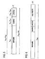
- Fig. 3A shows a first codeword Z1 which is the output of the FEC encoding block 21.
- Said first codeword Z1 comprises a data portion D, which generally corresponds to the input data word of the FEC encoding block 21 and which, according to this embodiment, comprises k input data bits s 1 , s 2 , ..., s k , and a basic parity portion Pb comprising, in this embodiment, m parity bits p 1 , p 2 , ..., p m .
- a receiver in particular a stationary receiver and/or a mobile receiver that is not affected by too many disturbances, is able to decode the input data encoded therein.
- Said second codeword Z2 comprises, in addition to the data portion D and the basic parity portion Pb, an auxiliary parity portion Pa of v auxiliary parity bits i i , i 2 , ..., i v .
- Said auxiliary parity portion Pa may be used by a receiver, for instance in case of transmissions errors, decoding errors and/or an insufficient quality of the decoding, as incremental redundancy in addition to the codeword Z1 for decoding.
- auxiliary parity bits i i , i 2 , ..., i v may be used for decoding, in addition to the first codeword Z1, to increase the probability of correct and error-free (or at least an increased quality of) decoding.
- the auxiliary parity portion Pa will also be mapped onto the transmitter output data stream for eventual reception and use by the receiver. Said mapping will be explained below in more detail.
- the combination of the codeword Z1 and the auxiliary parity portion Pa (of the second codeword Z2) can also be regarded as a "total" codeword of a "total" code having a lower code rate than the first code of the codeword Z1, i.e. the codeword Z1 can be regarded as a basic codeword portion B of this "total" codeword and the auxiliary parity portion Pa can be regarded as a auxiliary parity portion A of this "total” codeword.
- this "total" codeword is identical to the codeword Z2. This does, however, not hold for all embodiments as will be shown below.
- the transmitter input data stream to the encoder 14 is generally segmented into frames referred to as BBFrames comprising K bch bits as exemplarily depicted in Fig. 4 .
- a first codeword Z1 (in this context) generated therefrom by the BCH encoder 40 and the first encoding block 21, i.e. in accordance with the encoding as performed according to the DVB-T2 standard, is schematically depicted in Fig. 5 .
- This codeword is a standard FEC codeword comprising the (systematic) input data portion, which itself consists of K bch bits, followed by N bch - K bch parity bits of the BCH encoder, followed by N ldpc - K ldpc parity bits of the LDPC encoder. In total, this codeword comprises N ldpc bits.
- K ldpc corresponds to k (i.e. the portions BBFRAME and BCHFEC are regarded as the input data word D) and N ldpc corresponds to k+m (i.e. the portion LDPCFEC is regarded as the basic parity portion Pb).
- the second encoding block 31 computes auxiliary parity bits for use as incremental redundancy, based on its input, which generally is the same as the input of the FEC encoding block 21.
- auxiliary parity bits which can be partitioned into q sub-portions.
- the k-th sub-portion is of length v (k) .
- Fig. 6 shows such an embodiment of a codeword Z2 (in the context of DVT-T2) generated by the second FEC encoding block 31 which, according to this embodiment, also comprises BCH and LDPC encoding, but additionally generates v auxiliary parity bits for use as incremental redundancy at the receiver in case of need.
- LDPC parity bits e.g. of a known LDPC code
- their use as incremental redundancy is generally known, e.g. from Kim J. et al. "Design of Rate-Compatible Irregular LDPC Codes for Incremental Redundancy Hybrid ARQ Systems", ISIT 2006, Seattle, USA, July 9-14, 2006 .
- a diagram illustrating such an "extended" code and its generation is shown in Fig. 19 . Therein, it is shown how each of the bits of the basic codeword portion B and of the auxiliary parity portion A are generated from other, in particular all "previous" bits in the codeword by use of modulo-2 units 45. This way of generating the codeword ensures that a decoder can decode a codeword by use of only the basic codeword portion B or by additional use of one or more of the auxiliary parity bits of the auxiliary parity portion A.
- the data mapper 16 shall be explained.
- the first codeword generally, the basic codeword portion B
- the auxiliary parity portion generally, the auxiliary codeword portion A
- the second encoding unit 30 for the same input data word are mapped in any way onto the frames of the transmitter output data stream O.
- the corresponding data portion D, the basic parity portion Pb and the auxiliary parity portion Pa are mapped onto the transmitter output data stream O according to the present invention.
- the data mapper 16 is adapted such that the data portion D and the basic parity portion Pb are mapped onto a different portion, for instance onto a different frame, than the corresponding auxiliary parity portion Pa of the same codeword.
- This provides the advantage that regular channel disturbances do generally not affect both the data portion D and the basic parity portion Pb on the one hand and the auxiliary parity portion Pa on the other hand.
- FIG. 7 illustrates the framing structure as applied according to the DVB-T2 standard.
- a superframe structure is applied where each superframe is subdivided into a multitude of T2 frames. After each predetermined number of consecutive T2 frames an FEF part (Future Extension Frame part) is inserted for future use. This is also schematically illustrated in the data stream structure shown in Fig. 8 .
- the data mapper 16 is adapted in one embodiment such that the data portion and the basic parity portion of a codeword, which can also be regarded as the basic codeword portion B and, in this embodiment, the basic codeword Z1 (see Fig. 3A ), are mapped onto the T2 frames and that the auxiliary parity portion Pa (generally the auxiliary codeword portion A) of the same codeword (taken from the auxiliary codeword Z2) is mapped onto the FEF part, preferably the FEF part following next to the T2 frame(s) into which the corresponding data portion D and basic parity portion Pb are mapped.
- Such a mapping provides the advantage that a conventional receiver in accordance with the DVB-T2 standard simply ignores the data transmitted in the FEF parts and only evaluates the data transmitted in the T2 frames as usual.
- Mobile receivers may also access the T2 frames and decode, in a first step, the codewords embedded therein.
- such mobile receivers access the FEF parts and use parts or all of the auxiliary parity data contained therein for decoding, in a second step, the codeword received in the corresponding T2 frame again, as will be explained in more detail below.
- all data required for decoding by a mobile receiver are transmitted in the FEF parts, i.e. a complete codeword comprising the data portion D, the basic parity portion Pb and the auxiliary parity portion Pa is mapped onto the FEF part.
- Such mobile receivers thus ignore the data contained in the T2 frames which are only accessed by stationary receivers, in particular receivers in accordance with the DVB-T2 standard.
- the auxiliary parity portion Pa is preferably modulated in a different way than the data portion D and the basic parity portion Pb.
- an auxiliary modulation code is applied for modulating the auxiliary parity portions, said auxiliary modulation code being orthogonal to a basic modulation code that is used for modulating the data portions and the basic parity portions, generally after the data mapping.
- an orthogonal time, frequency, space (MIMO) or a spreading code may be applied.
- MIMO frequency, space
- Another possibility would be the application of hierarchical modulation.
- the framing structure applied by the transmitter 10 may also be completely different than the framing structure used according to the DVB-T2 standard as shown in Figs. 7 and 8 .
- any framing structure e.g. a newly created framing structure, may be applied as long as the receiver is able to detect or know in advance where to find the data portions and the various parity portions.
- BCH and LDPC encoding is not required, but other codes (e.g. other FEC codes) can be applied.
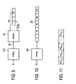
- FIG. 9 A simplified block diagram of another embodiment of an encoder 142 and a data mapper 16 is shown in Fig. 9 .
- the encoder 142 comprises a single encoding unit by which the input data words are encoded, i.e. by which both the basic parity portions Pb and the auxiliary parity portions Pa are generated.
- the complete codeword Z2 (see Fig. 3B ) is generated.
- These codewords Z2 are provided to the data mapper 16 which splits off the auxiliary parity portion Pa and maps it onto a different portion of the transmitter output data stream than the data portion D and the basic parity portion Pb.
- the data mapper 16 generally the same embodiments exist as have been explained above.
- the data input 12 may be adapted for not only receiving a single transmitter input data stream, but may generally receive a number n of transmitter input data streams, for instance a number n of physical layer pipes.
- the encoder 14 may, in such a case, however be adapted to select if a transmitter input data stream is encoded as usual, i.e. according to the basic code and without the generation of any auxiliary parity data, or if another code having a lower code rate shall be applied and auxiliary parity data for use as incremental redundancies by the receiver shall be generated. It may also be possible that various codes with different (e.g. decreasing) code rates may be available for application by the encoder so that even more than two possibilities exist.
- Which code and which code rate to apply may be prescribed, e.g. by the operator of the transmitter or the owner of the broadcast channel. But the choice of the code may also depend on the kind of data to be transmitted. For instance, audio data may be encoded with a code having a higher code rate than video data so that only for video data such auxiliary parity data are generated or vice versa. As another example, any decoding errors may be acceptable when watching news, but may not be acceptable when watching a movie for which auxiliary parity data may thus be generated and transmitted.
- FIG. 10 A still further embodiment of an encoder 143 is illustrated in Fig. 10 .
- Said encoder 143 is adapted such that it generates two or more auxiliary parity sub-portions Pa1, Pa2, Pa3 in addition to the data portion D and the basic parity portion Pb thus forming a codeword Z3.
- the auxiliary parity sub-portions Pa1, Pa2, Pa3 of the codeword Z3 can be seen as segments of the auxiliary parity portion Pa of the codeword Z2, having in total the identical content, although generally the auxiliary parity sub-portions Pa2 and Pa3 can also be additional auxiliary parity portions in addition to the auxiliary parity portion Pa1 that (alone) corresponds to the auxiliary parity portion Pa.
- auxiliary parity sub-portions Pa1, Pa2, Pa3 are generated such that they can be stepwise used by a decoder as incremental redundancies.
- the codeword generally it is possible to decode the codeword by use of only the data portion D and the basic parity portion Pb (i.e. the basic codeword portion). If such decoding fails, the first auxiliary parity sub-portion Pa1 (i.e. a part of the auxiliary codeword portion) may be used in addition for decoding. If this again fails (or provides insufficient quality) the second auxiliary parity sub-portion Pa2 may be added and so on.
- All the auxiliary parity sub-portions Pa1, Pa2, Pa3 may be grouped together and mapped onto a single portion of the transmitter output data stream.
- This provides the advantage that a receiver which, after using the first auxiliary parity sub-portion, can decode the codeword with sufficient quality, can fall into sleeping mode for the time period during which other auxiliary parity sub-portions are transmitted that are no longer needed and/or from other data streams that shall currently not be decoded. This provides some power saving and less calculation efforts at the receiver.
- auxiliary parity sub-portions of various input frames (BBFrames, generally referred to as input data words) is shown in Fig. 11 .
- the input frames are enumerated in this embodiment by two indices (e, f), where the index e corresponds to the PLP_ID (PLP number, also referred to here as the number of the transmitter input data stream), and where f relates to the input frame (input data word).
- the index e is part of a set S 2 , i.e., the set of PLPs that are protected by additional incremental redundancy.
- S 2 is a subset of S 1 of PLPs that are protected by additional incremental redundancy according to the present invention since, as mentioned above, not all PLPs need necessarily use this idea.
- the f-th input frame of the e-th PLP is denoted as I e,f .
- the auxiliary parity sub-portions Pal e,f up to Pay e,f may be mapped onto an FEF frame in the sequence as shown in Fig. 11 and may belong to codewords mapped onto preceding T2 frames.
- Fig. 12 illustrates more details of the arrangement of data within a T2 frame in accordance with the DVB-T2 standard.
- the PLPs in a T2 frame underlie a certain order.
- P1, P2 and after common PLPs the PLPs of type 1 are transmitted without subslicing, then PLPs of type 2 are transmitted with subslicing.
- Both type 1 and type 2 PLPs have a fixed order which is signalled in the P2 preamble. This is also illustrated and explained in detail in the DVB-T2 standard, which explanation is herein incorporated by reference.
- Fig. 13 shows a proposal for arranging the auxiliary parity sub-portions in an FEF frame that is made similar to the arrangement of the PLPs in the T2 frame.
- the FEF also starts with a P1 preamble, i.e. an OFDM symbol, which is made to be used for (time, frequency) synchronization purposes, for channel estimation and for signalling the most important transmission parameters.
- the subsequent (one or more) P2 preamble(s) contain(s) more detailed information about the content of the FEF.
- the arrangement of the auxiliary parity sub-portions in the FEF in this embodiment is such that the order of the partitioned auxiliary parity sub-portions is derived from the slicing/ordering of the T2 frames, even if not all PLPs from T2 frames have auxiliary parity sub-portions to be mapped onto the FEFs.
- the order of the auxiliary parity sub-portions does not have to be signalled explicitly.
- the auxiliary parity portions are sorted in the time domain, in particular such that the first portion Pa1 e,f , for instance the more robust portion, of all PLPs having auxiliary parity portions is inserted at the beginning of the FEF, i.e. right after the preambles P1, P2.
- the second portion Pa2 of all PLPs with auxiliary parity portions follows afterwards etc. As mentioned above, if basic codewords are not decodable the related first portion Pa1 of the FEF is evaluated. If the receiver can now correctly decode the overall codeword without error it falls into sleeping mode to save power. Otherwise it will additionally include the second auxiliary parity portion Pa2 etc.
- the FEFs may contain signalling information, e.g. in the preamble or in a ModCod header, regarding the link of the auxiliary parity portions used in the FEFs and the PLPs mapped onto the T2 frames (which itself remain unchanged in this embodiment). Further, other data may be contained in the FEFs as well, for instance low-bitrate information for use by a mobile receiver.
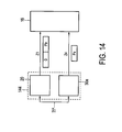
- Fig. 14 shows still another embodiment 144 of an encoder according to the present invention. Similar to the embodiment shown in Fig. 2 the encoder 144 comprises a first encoding unit 20 for encoding, according to said first code, the input data word into said basic codeword Z1 as explained above. Further, a second encoding unit 30a is provided for encoding, according to said second code, the input data word into an auxiliary codeword portion (which can be regarded as an auxiliary codeword Z4) comprising only said auxiliary parity portion Pa. Hence, the second encoding unit 30a only generates the data ultimately necessary for improving decoding at the decoder, if required, but does not generate other codeword portions that are already generated by the first encoding unit 20.
- auxiliary codeword portion which can be regarded as an auxiliary codeword Z4
- Fig. 15 shows a schematic block diagram of a receiver 50 for use in a broadcasting system comprising a transmitter 10 as illustrated above.
- the receiver 50 is particularly adapted for making use of the auxiliary parity portion (generally, the auxiliary codeword portion) as incremental redundancy in case of erroneous or low quality decoding.
- the auxiliary parity portion generally, the auxiliary codeword portion
- the receiver 50 comprises a data input 52 for receiving a receiver input data stream O' which generally corresponds to a transmitter output data stream O that has been transmitted over a broadcast channel of the broadcasting system by a transmitter and which may thus be affected by disturbances that may appear in such a broadcasting system, particularly in case of using mobile receivers which are the main application of the present invention on the receiver side.
- a demodulator 53 is provided that is interrelated with the (optional) modulator 17 of the transmitter 10 for demodulating the received receiver data input stream O'.
- a demapper 54 demaps the (optionally demodulated) receiver data input stream O', particularly at least the data portions and the basic parity portions (i.e. the basic codeword portions) of the codewords mapped into the receiver data input stream O' as will be explained below in more detail.
- a decoder 56 then decodes these codewords by use of the basic codeword portions according to the same code as applied by the encoder 14 of the transmitter 10.
- a check unit 58 is provided in the receiver 50 by which it is checked if decoding has been made correctly and/or with sufficient quality and/or below a tolerable error level as will be explained below. If the decoding is made without errors or with sufficient quality the decoded data are provided to an output unit 60.
- the output thereof might be one or more receiver output data streams 11' 12', ..., In' which should as much as possible correspond to the transmitter input data streams 11, 12, ..., In.
- a feedback loop 62 is provided from the check unit 58 to the demapper 54 and/or the decoder 56 in order to make use of the auxiliary parity portion (generally, the auxiliary codeword portion) (completely or in part) for improving the quality of decoding.
- the demapper 54 then also demaps the auxiliary parity portion (completely or in part) from the (optionally demodulated) receiver input data stream O'.
- a feedback loop 62 is also provided from the check unit 58 to the demodulator 53, e.g. if auxiliary parity portions are required by the decoder 56 from another receiver input data stream, e.g. from data received at a different antenna in a MIMO receiver or from another channel (e.g. using another frequency).
- a check can be made by the check unit 58 if the decoding has now been made error-free or with sufficient quality, and, if not, a still further part of the auxiliary parity portion can be used in another iteration of demapping and decoding. If, on the other hand, the complete auxiliary parity portion of a codeword has already been completely used for decoding the check can also be omitted and the decoded data can be outputted directly.
- a first embodiment 561 of the decoder 56 is schematically depicted in Fig. 16 .
- the decoder 561 comprises a first decoding unit 70 and a second decoding unit 80, similarly as the embodiment of the encoder 141 depicted in Fig. 2 .
- an additional decoder 90 e.g. a BCH decoder
- the first decoding unit 70 generally corresponds to the decoding unit as used in receivers in accordance with the DVB-T2 standard.
- a time deinterleaver 71 It comprises a time deinterleaver 71, a cell deinterleaver 72, a cyclic delay remover 73, a constellation demapper 74, a bit deinterleaver 75 and a first LDPC decoding block 76.
- a decoder is, for instance, explained in more detail in the DVB document A133, February 2009 "Implementation Guidelines for a Second Generation Digital Terrestrial Television Broadcasting System (DVB-T2)" which is herein incorporated by reference.
- This first decoding unit 70 thus is provided with the data portions D' and the basic parity portions Pb' (generally the basic codeword portion B') as demapped by the demapper 54 from a received receiver input data stream O' and decodes, as usual, these codewords.
- a second decoding unit 80 which basically comprises the same elements, in particular a time deinterleaver 81, a cell deinterleaver 82, a cyclic delay remover 83, a constellation demapper 84, a bit deinterleaver 85 and a second decoding block 86, whose function is identical to the function of the respective elements of the first decoding unit 70.
- the parameters of those blocks may differ, if different parameters are applied in the encoder, e.g. in the second encoding unit 30 (see Fig. 2 ).
- the second decoding unit 80 is, however, provided, in addition to the data portions D' and the basic parity portions Pb', with the additional auxiliary parity portion Pa' (generally the auxiliary codeword portion A') (completely or in part) for decoding the codewords with high reliability using said auxiliary parity portion Pa' as redundancy information.
- the second decoding unit 80 only becomes active in case of need, i.e. if "instructed" by the check unit 58 through feedback loop 62.
- the second decoding unit 80 is provided with only the auxiliary codeword portion A'.
- FIG. 17 An alternative embodiment 562 of a decoder is depicted in Fig. 17 .
- the demapper 54 accesses the T2 frames of a received receiver data input stream O' to demap the data portions D' and the basic parity portions Pb' therefrom and accesses FEF frames to demap the auxiliary parity portions Pa' therefrom, i.e. the demapper 54 is adapted to interrelate with the mapper 16 as illustrated in Fig. 9 .
- the decoder 562 only comprises a single decoding unit which is both able to decode the codewords according to the first code (with a higher code rate) based on only the data portion D' and the basic parity portion Pb' and according to the second code (with a lower code rate) using as redundancy information (part of or all of) the auxiliary parity portion Pa', if needed.
- a standard LDPC decoder as, for instance, provided in a DVB-T2 receiver accepts at its input a (channel disturbed) codeword, as well as signalling information about the code rate and the length of the codewords (either 16200 or 64800 bits). Based on the signalling information, it applies an appropriate decoding algorithm (typically so called iterative message passing) based on that particular code realization and outputs an estimate of the data portion.
- a decoding algorithm typically so called iterative message passing
- an extended LDPC decoder included in the decoder 56 in particular the extended LDPC decoder 76 and 86, which receive in addition auxiliary codeword portion, in particular auxiliary parity bits.
- the number of auxiliary bits is generally signalled in addition to the applied code rate and the length of the basic codeword portion to the decoder. Given these parameters, the decoder 56 applies an appropriate decoding algorithm based on this extended (or "total") code.
- the demapper and the decoder are preferably adapted to stepwise add more parts ("sub-portion") of an auxiliary parity portion to improve the decoding.
- the demapper and the decoder are adapted for going into a sleeping mode while other parts of the (segmented; see for instance Fig. 13 ) auxiliary sub-portions are provided in a received receiver input data stream, i.e. those additional segments of an auxiliary parity sub-portion are preferably not demapped and used for decoding. This particularly saves power in the receiver which is especially advantageous in case of mobile receivers using a battery as power source.
- a generic LDPC decoder has as input a received codeword (with or without additional parity bits) as well as signalling information about the code rate and the codeword length. The latter is in addition implicitly updated by the feedback loop 62, which signals, if (and how many) auxiliary parity bits are appended.
- the LDPC decoder in the decoder 56 outputs its estimates on each code bit of the (received) codeword C', i.e. an estimate C" on the codeword C'.
- the bitwise estimates are expressed in terms of log likelihood ratios (LLRs), whose magnitude reflects the reliability of the estimate.
- the indicator E from the check unit 58 is optional and gives an estimate of how many additional auxiliary parity sub-portions are still needed. In case of E > 1, the LDPC decoder 56 does not even have to try to decode the next larger codeword, but has to wait for E additional auxiliary parity sub-portions to restart decoding.
- the last criterion (d) can also offer an estimate of how unreliable the codeword (after decoding) is. Assuming that the following auxiliary code portions have a similar quality than the previous codeword, an estimate E can be made about how many additional portions are needed for successful decoding.
- the encoder of the transmitter may also be adapted such that the auxiliary parity portion (generally, the auxiliary codeword portion) may not (only) comprise "real" parity information, but that it may also comprise a repetition of (part of or all) of the information of the "basic" codeword, i.e. (some or all) bits of the data portion D and/or the basic parity portion Pb (i.e. of the basic codeword portion).
- the auxiliary parity portion Pa simply comprises a copy of the data portion D and/or the basic parity portion Pb. This will also improve decoding if the basic codeword is disturbed but the auxiliary parity portion is not (or less) disturbed.
- both the basic codeword portion and the auxiliary codeword portion are disturbed, by use of both portions for decoding the result of the decoding may be improved, e.g. by applying the principle of soft combining, e.g. by improving the soft values obtained in a first decoding step using only the basic codeword portion in a second decoding step using in addition the auxiliary codeword portion.
- the broadcasting system generally comprises a transmitter (Tx) 10 and one or more receivers (Rx) 50a, 50b, 50c. While it is generally sufficient that the transmitter 10 has a single antenna for transmitting the transmitter output data stream O, here in this embodiment the transmitter 10 is provided with two antennas 19a, 19b.
- both antennas can be used for simultaneously transmitting the identical transmitter output data stream O (or a modified stream thereof, e.g. in accordance with the Alamouti scheme of the DVB-T2 standard), for instance to increase coverage.
- the data mapper 161 provided in this embodiment of the transmitter 10 is adapted for generating two transmitter output data stream O1 and O2, wherein the data portions D and the basic parity portions Pb of codewords (i.e. the basic codeword portions) are mapped onto the first transmitter output data stream O1 and wherein the auxiliary parity portions Pa of codewords (i.e. the auxiliary codeword portions) are mapped onto the second transmitter output data stream 02.
- the first antenna 19a can then be provided with the first transmitter output data stream O1 for transmission and the second antenna 19b can be provided with the second transmitter output data stream 02 for transmission. For instance, during the transmission of T2 frames only the first transmitter output data stream O1 is transmitted, while during the transmission of FEFs both transmitter output data streams O1 and 02 are transmitted.
- the first transmitter output data stream O1 may be transmitted by a horizontally polarized antenna, whereas the second transmitter output data stream 02 my be transmitted by a vertically polarized antenna, or vice versa.
- a MIMO precoder 162 is provided to which said first and second transmitter output data streams O1, 02 are provided from the data mapper 161 for precoding them according to any MIMO precoding scheme.
- the first and second transmitter output data streams O1, 02 can be spatially multiplexed onto the precoded transmitter output data streams O1*, O2* which are then transmitted by the antennas 19a, 19b, or Alamouti precoding can be applied to the first and second transmitter output data streams O1, 02.
- the precoded transmitter output data streams O1*, O2* may then both contain a mix of data from the first and second transmitter output data streams O1, 02.
- the transmitter 10 is provided with two antennas 19a, 19b. It should be noted, however, that the transmitter, in particular a MIMO transmitter, comprises more than two antennas to which said precoded transmitter output data streams O1*, O2* are provided for transmission.
- a first receiver 50a having a single antenna 61 may be adapted for receiving only the first transmitter output data stream O1 (as first receiver input data stream O1'), but not the second transmitter output data stream O2.
- a receiver 50a might be an existing, e.g. legacy or stationary, receiver that is not adapted for using any auxiliary parity portions at all.
- the transmitter 10 particularly the second transmitter output data stream 02 is directed to reception by mobile receivers in accordance with a new standard, e.g. the DVB-NGH standard
- the receiver 50a could be a stationary receiver in accordance with the DVB-T2 standard.
- the receiver 50b comprises two antennas 61a, 61b.
- the first antenna 61a is adapted for reception of the first transmitter output data stream O1 (as first receiver input data stream O1')
- the second antenna 61b is adapted for reception of the second transmitter output data stream 02 (as second receiver input data stream O2').
- the two antennas 19a, 19b of the transmitter 10 make use of different transmission channels, e.g. transmission frequencies
- the two antennas 61a, 61b of the receiver 50b can be adapted for reception on the same respective transmission channel.
- a third embodiment of a receiver 50c again has a single antenna 61, but is adapted for reception of the signals from both antennas 19a, 19b.
- the receiver 50c comprises means for internally splitting up or decomposing the two received input data streams O1', O2' accordingly.
- the embodiment of the receiver 50b having two separate antennas 61a, 61b for receiving the different transmitter output data streams O1, 02 separately, provides the advantage that the second antenna 61b and the subsequent processing means within the receiver 50b need only be activated if any auxiliary parity portions are required as incremental redundancies for improvement of the decoding.
- receiver 50c which, in the latter case, can switch between reception of the first or second transmitter output data streams O1, 02 or which continuously receives both transmitter output data streams O1, 02. Further, such an embodiment generally also provides an increased spectral density.
- the data demapper 54 of the receiver 50 is, of course, adapted appropriately for demapping the required data from the receiver data input stream, i.e. the demapper 54 is aware of the particular framing structure and/or the locations at which the respective data are placed in the receiver data input stream.
- Known measures for signalling this information to the receiver from the transmitter and/or for prescribing this information, for instance in a standard, and for enabling the transmitters and receivers accordingly are generally applied to ensure this.
- the framing structure applied according to the present invention may generally be adapted to be in consistence with the framing structure according to an existing standard, e.g. the DVB-T2 standard, so that existing receivers in accordance with this standard may also receive and process such data streams, even if they do not make use of the auxiliary parity information contained therein as incremental redundancy.
- an existing standard e.g. the DVB-T2 standard
- the framing structure may be freely selected and newly created according to specific needs of the broadcasting system.
- the present invention can be applied in all broadcasting systems, by which data are transmitted over a channel.
- the invention can be applied in a DAB system which shall be explained with reference to Fig. 20 .
- Fig. 20 shows the structure of a transmission frame as described in the DAB standard (ETS 300 401 "Radio broadcasting systems; Digital Audio Broadcasting (DAB) to mobile, portable and fixed receivers", May 1997, RE/JPT-00DAB-4).
- the DAB transmission system combines three channels, in particular a Synchronization Channel which is used internally with the transmission system for basic demodulator functions (e.g.
- FIC Fast Information Channel
- MSC Main Service Channel
- the MSC can also be seen as being made up of Common Interleaved Frames (CIFs), comprising Capacity Units (CU) as smallest addressable units.
- CIFs Common Interleaved Frames
- CU Capacity Units
- Each sub-channel of the MSC occupies an integral number of consecutive CUs and is individually convolutionally encoded. More details regarding the structure of the transmission frame and its content can be found in the above cited DAB standards, which explanations are herein incorporated by reference.
- one of the sub-channels e.g. SubCh a could comprise the basic codeword version
- one or more of the subsequent sub-channels e.g. SubCh b
- a receiver can now process SubCh a and, if necessary, SubCh b for improving the decoding.
- the auxiliary codeword portion can be further segmented into sub-portions all carried in the same sub-channel or carried in various sub-channels. This again has the advantage that the receiver can fall into sleeping mode after successful decoding until the next basic codeword portion is transmitted.
- FIC Fast Information Channel
- the error correction code applied in DAB is a convolution code.
- Different code rates are generally achieved according to DAB by puncturing of a mother code.
- This mother code generally has a code rate of 1/4, and by puncturing of certain parity bits higher code rates are obtained.
- These punctured parity bits could be used as auxiliary parity bits for providing incremental redundancy in accordance with the present invention.
- a completely new mother code is also applicable, from which all the DAB code rates can be obtained by puncturing and where the punctured bits are used as auxiliary parity bits in accordance with the present invention.
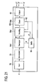
- Fig. 21 shows a block diagram of another embodiment of a receiver 50d.
- the basic codeword portions B and the auxiliary codeword portions A are mapped by the transmitter onto the transmitter output data stream O such that a basic codeword portion of a codeword is received by a receiver before the corresponding auxiliary codeword portion is received.
- the data mapper can also be adapted for mapping the basic codeword portions B and the auxiliary codeword portions A onto frames of a transmitter output data stream such that the auxiliary codeword portion of a codeword is received by a receiver before the corresponding basic codeword portion is received.
- the transmitter is adapted in this way.
- the data demapper 54d is thus adapted to demap the (first received) auxiliary codeword portions A' from the receiver input data stream O' and forward them to a buffer 64. Thereafter (whenever received) the corresponding basic codeword portions B' are demapped and forwarded to the decoder 56d for decoding them. If the check in the check unit 58d shows that additional redundancies shall be used for improved decoding the buffer 64 is informed via the feedback loop 62 to provide the buffered auxiliary codeword portion A' to the decoder 56d and the decoder is informed to then decode the codeword (now by additional use of the (complete or partial) auxiliary codeword portion again. If it is clear that the decoding of the corresponding codeword is correct the buffered auxiliary codeword portion (if any) is deleted from the buffer.
- This embodiment provides the advantage that no waiting times (for waiting for the auxiliary parity portion, if the decoding was erroneous based on the basic codeword portion) occur, which is particularly important for reducing zapping times or for mobile receivers.
- this embodiment also provides the advantage that no interruption of the service occurs (due to waiting for reception of auxiliary codeword portions) in case of (e.g. sudden) bad reception conditions of the basic codeword portions.
- the present invention thus provides an effective and easily implementable measure for improving the reliability of decoding, particularly for mobile receivers in a broadcasting system, without any feedback from a receiver to the transmitter.
- the DVB-T2 framing structure is kept unchanged and the FEFs contain the additional redundancy, i.e. the auxiliary codeword portion
- the FEFs themselves with the embedded incremental redundancy, which can (and typically will) select transmission (e.g. OFDM) parameters that have a better behaviour in mobile channels.
- the most important ones are lower FFT sizes and higher pilot pattern densities (being related to the FFT and guard interval sizes).
- the incremental redundancy data in the FEFs can additionally be protected by using lower modulation schemes, other interleaving depths etc..
- the time interleaver depth chosen in the FEFs could, for example, complement the time interleaver depth of the T2 frames. If the T2 frame time interleaver fails (e.g. signal interrupted for a dedicated time (e.g. due to a tunnel etc.)), the other settings in the FEF time interleaver might be better suited and allow overall correct decoding. Different time interleaver settings of the T2 frame and the FEF frame overall improve the system performance.
- the receiver in accordance with the present invention benefits therefore from the fact that in addition to the basic T2 reception the data in the FEFs (i.e. additional incremental redundancy) is more robust in mobile channels.
- Another main advantage of preferred embodiments of the present invention is that broadcasters do not have to transmit the data for mobile, (e.g. NGH) receivers, but only incremental redundancy is transmitted to enable a more robust reception of T2 data even with a mobile receiver. Thus, transmission bandwidth is utilized most efficiently.
- a computer program may be stored / distributed on a suitable medium, such as an optical storage medium or a solid-state medium supplied together with or as part of other hardware, but may also be distributed in other forms, such as via the Internet or other wired or wireless telecommunication systems.
- a suitable medium such as an optical storage medium or a solid-state medium supplied together with or as part of other hardware, but may also be distributed in other forms, such as via the Internet or other wired or wireless telecommunication systems.
Priority Applications (1)
| Application Number | Priority Date | Filing Date | Title |
|---|---|---|---|
| EP10765646.4A EP2502378B1 (en) | 2009-11-17 | 2010-10-18 | Transmitter and transmission method for broadcasting data in a broadcasting system providing incremental redundancy |
Applications Claiming Priority (3)
| Application Number | Priority Date | Filing Date | Title |
|---|---|---|---|
| EP09176176 | 2009-11-17 | ||
| EP10765646.4A EP2502378B1 (en) | 2009-11-17 | 2010-10-18 | Transmitter and transmission method for broadcasting data in a broadcasting system providing incremental redundancy |
| PCT/EP2010/065641 WO2011061031A1 (en) | 2009-11-17 | 2010-10-18 | Transmitter and transmission method for broadcasting data in a broadcasting system providing incremental redundancy |
Publications (2)
| Publication Number | Publication Date |
|---|---|
| EP2502378A1 EP2502378A1 (en) | 2012-09-26 |
| EP2502378B1 true EP2502378B1 (en) | 2015-12-16 |
Family
ID=43035762
Family Applications (1)
| Application Number | Title | Priority Date | Filing Date |
|---|---|---|---|
| EP10765646.4A Not-in-force EP2502378B1 (en) | 2009-11-17 | 2010-10-18 | Transmitter and transmission method for broadcasting data in a broadcasting system providing incremental redundancy |
Country Status (8)
| Country | Link |
|---|---|
| US (2) | US9444582B2 (pl) |
| EP (1) | EP2502378B1 (pl) |
| CN (2) | CN105207742B (pl) |
| AU (1) | AU2010321141A1 (pl) |
| IN (1) | IN2012DN05172A (pl) |
| RU (1) | RU2012120334A (pl) |
| TW (1) | TWI513221B (pl) |
| WO (1) | WO2011061031A1 (pl) |
Families Citing this family (85)
| Publication number | Priority date | Publication date | Assignee | Title |
|---|---|---|---|---|
| WO2011062424A2 (en) | 2009-11-18 | 2011-05-26 | Samsung Electronics Co., Ltd. | Method and apparatus for transmitting and receiving data in a communication system |
| CN102835088B (zh) * | 2010-02-11 | 2016-02-10 | 索尼公司 | 多载波广播系统中的解映射装置和用于数据接收的方法 |
| US9236927B2 (en) | 2010-02-25 | 2016-01-12 | Sony Corporation | Transmission apparatus and method for transmission of data in a multi-carrier broadcast system |
| US10681568B1 (en) | 2010-05-28 | 2020-06-09 | Cohere Technologies, Inc. | Methods of data channel characterization and uses thereof |
| US9130638B2 (en) | 2011-05-26 | 2015-09-08 | Cohere Technologies, Inc. | Modulation and equalization in an orthonormal time-frequency shifting communications system |
| US9444514B2 (en) | 2010-05-28 | 2016-09-13 | Cohere Technologies, Inc. | OTFS methods of data channel characterization and uses thereof |
| US11943089B2 (en) | 2010-05-28 | 2024-03-26 | Cohere Technologies, Inc. | Modulation and equalization in an orthonormal time-shifting communications system |
| US9071285B2 (en) | 2011-05-26 | 2015-06-30 | Cohere Technologies, Inc. | Modulation and equalization in an orthonormal time-frequency shifting communications system |
| US9071286B2 (en) | 2011-05-26 | 2015-06-30 | Cohere Technologies, Inc. | Modulation and equalization in an orthonormal time-frequency shifting communications system |
| US10667148B1 (en) | 2010-05-28 | 2020-05-26 | Cohere Technologies, Inc. | Methods of operating and implementing wireless communications systems |
| WO2012070837A2 (ko) * | 2010-11-23 | 2012-05-31 | 엘지전자 주식회사 | 방송 신호 송/수신기 및 방송 신호 송/수신 방법 |
| KR101998085B1 (ko) * | 2010-12-10 | 2019-07-09 | 선 페이턴트 트러스트 | 송신방법, 송신장치, 수신방법 및 수신장치 |
| WO2012081870A2 (ko) | 2010-12-14 | 2012-06-21 | 엘지전자 주식회사 | 방송 신호 송/수신기 및 방송 신호 송/수신 방법 |
| GB2499424B (en) * | 2012-02-16 | 2016-06-01 | Canon Kk | Methods for decoding, methods for retrieving, method for encoding, method of transmitting, corresponding devices, information storage means and computer |
| US10090972B2 (en) | 2012-06-25 | 2018-10-02 | Cohere Technologies, Inc. | System and method for two-dimensional equalization in an orthogonal time frequency space communication system |
| US9929783B2 (en) * | 2012-06-25 | 2018-03-27 | Cohere Technologies, Inc. | Orthogonal time frequency space modulation system |
| US10411843B2 (en) | 2012-06-25 | 2019-09-10 | Cohere Technologies, Inc. | Orthogonal time frequency space communication system compatible with OFDM |
| US10469215B2 (en) | 2012-06-25 | 2019-11-05 | Cohere Technologies, Inc. | Orthogonal time frequency space modulation system for the Internet of Things |
| CN103684666B (zh) * | 2012-09-13 | 2016-12-21 | 中国科学院上海高等研究院 | 在ngb-w通信系统中实现时间交织和解时间交织的方法 |
| CN104813604B (zh) * | 2012-11-28 | 2017-10-31 | 索尼公司 | 使用冗余数据接收广播系统中的数据的接收器 |
| WO2014082933A1 (en) | 2012-11-28 | 2014-06-05 | Sony Corporation | Control device and method for use in a broadcast system |
| WO2014082997A1 (en) * | 2012-11-28 | 2014-06-05 | Sony Corporation | Receiver for receiving data in a broadcast system |
| US10025551B2 (en) * | 2013-03-07 | 2018-07-17 | Disney Enterprises, Inc. | Method and system for real-time audio broadcast |
| US9136874B2 (en) * | 2013-03-15 | 2015-09-15 | Ibiquity Digital Corporation | Method and apparatus for transmission and reception of in-band on-channel radio signals including complementary low density parity check coding |
| WO2014204181A1 (en) | 2013-06-19 | 2014-12-24 | Lg Electronics Inc. | Apparatus for transmitting broadcast signals, apparatus for receiving broadcast signals, method for transmitting broadcast signals and method for receiving broadcast signals |
| US9684942B2 (en) * | 2013-09-11 | 2017-06-20 | Apple Inc. | Link aggregator for an electronic display |
| KR102285934B1 (ko) | 2013-09-17 | 2021-08-04 | 삼성전자주식회사 | 송신 장치 및 그의 신호 처리 방법 |
| US10305632B2 (en) * | 2013-09-17 | 2019-05-28 | Samsung Electronics Co., Ltd. | Transmitting apparatus and signal processing method thereof |
| KR102264832B1 (ko) | 2013-09-26 | 2021-06-14 | 삼성전자주식회사 | 송신 장치 및 그의 신호 처리 방법 |
| WO2015046886A1 (en) | 2013-09-27 | 2015-04-02 | Lg Electronics Inc. | Apparatus for transmitting broadcast signals, apparatus for receiving broadcast signals, method for transmitting broadcast signals and method for receiving broadcast signals |
| US10425110B2 (en) | 2014-02-19 | 2019-09-24 | Samsung Electronics Co., Ltd. | Transmitting apparatus and interleaving method thereof |
| WO2015156568A1 (ko) | 2014-04-08 | 2015-10-15 | 엘지전자 주식회사 | 방송 신호 송신 장치, 방송 신호 수신 장치, 방송 신호 송신 방법, 및 방송 신호 수신 방법 |
| JP6367472B2 (ja) | 2014-08-21 | 2018-08-01 | エルジー エレクトロニクス インコーポレイティド | 放送信号送信装置、放送信号受信装置、放送信号送信方法、及び放送信号受信方法 |
| CN111031277B (zh) * | 2014-11-19 | 2022-02-22 | 无锡中感微电子股份有限公司 | 基于复合视频信号的数字数据发送和接收方法以及装置 |
| EP3226572A4 (en) * | 2014-11-26 | 2018-07-04 | LG Electronics Inc. | Apparatus and method for transmitting and receiving broadcast signal |
| WO2016120215A1 (en) | 2015-01-26 | 2016-08-04 | Sony Corporation | Receiver for receiving data in a broadcast system using redundancy data |
| US20160323060A1 (en) * | 2015-04-28 | 2016-11-03 | Intel IP Corporation | Apparatus, computer readable medium, and method for higher qam in a high efficiency wireless local-area network |
| WO2016183230A1 (en) | 2015-05-11 | 2016-11-17 | Cohere Technologies | Systems and methods for symplectic orthogonal time frequency shifting modulation and transmission of data |
| US10090973B2 (en) | 2015-05-11 | 2018-10-02 | Cohere Technologies, Inc. | Multiple access in an orthogonal time frequency space communication system |
| US10574317B2 (en) | 2015-06-18 | 2020-02-25 | Cohere Technologies, Inc. | System and method for providing wireless communication services using configurable broadband infrastructure shared among multiple network operators |
| US10404514B2 (en) | 2015-06-27 | 2019-09-03 | Cohere Technologies, Inc. | Orthogonal time frequency space communication system compatible with OFDM |
| CN108370355B (zh) | 2015-07-12 | 2021-02-12 | 凝聚技术公司 | 对多个窄带子载波的正交时间频率空间调制的方法和通信设备 |
| KR20190008827A (ko) | 2015-09-07 | 2019-01-25 | 코히어 테크널러지스, 아이엔씨. | 직교 시간 주파수 공간 변조를 이용한 다중액세스 |
| EP3378187B1 (en) | 2015-11-18 | 2022-03-30 | Cohere Technologies, Inc. | Orthogonal time frequency space modulation techniques |
| WO2017100666A1 (en) | 2015-12-09 | 2017-06-15 | Cohere Technologies | Pilot packing using complex orthogonal functions |
| WO2017117264A1 (en) * | 2015-12-29 | 2017-07-06 | Echostar Technologies L.L.C | Remote storage digital video recorder streaming and related methods |
| US10541781B2 (en) * | 2016-01-29 | 2020-01-21 | Intel IP Corporation | Rate matching using low-density parity-check codes |
| CN115694764A (zh) | 2016-02-25 | 2023-02-03 | 凝聚技术公司 | 用于无线通信的参考信号封装 |
| WO2017165697A1 (en) | 2016-03-23 | 2017-09-28 | Cohere Technologies | Receiver-side processing of orthogonal time frequency space modulated signals |
| US9667307B1 (en) | 2016-03-31 | 2017-05-30 | Cohere Technologies | Wireless telecommunications system for high-mobility applications |
| CN109845102B (zh) | 2016-03-31 | 2023-07-28 | 凝聚技术公司 | 使用正交时间频率空间调制的导频信号的信道获取 |
| CN109314682B (zh) | 2016-04-01 | 2021-09-21 | 凝聚技术公司 | 正交时频空间调制信号的迭代二维均衡 |
| WO2017173461A1 (en) | 2016-04-01 | 2017-10-05 | Cohere Technologies, Inc. | Tomlinson-harashima precoding in an otfs communication system |
| WO2017201467A1 (en) | 2016-05-20 | 2017-11-23 | Cohere Technologies | Iterative channel estimation and equalization with superimposed reference signals |
| WO2018031952A1 (en) | 2016-08-12 | 2018-02-15 | Cohere Technologies | Iterative multi-level equalization and decoding |
| EP3497907A4 (en) | 2016-08-12 | 2020-03-04 | Cohere Technologies, Inc. | LOCALIZED EQUALIZATION FOR INTER-CARRIER INTERFERENCE CHANNELS |
| WO2018031938A1 (en) | 2016-08-12 | 2018-02-15 | Cohere Technologies | Multi-user multiplexing of orthogonal time frequency space signals |
| WO2018064587A1 (en) | 2016-09-29 | 2018-04-05 | Cohere Technologies | Transport block segmentation for multi-level codes |
| WO2018064605A1 (en) | 2016-09-30 | 2018-04-05 | Cohere Technologies | Uplink user resource allocation for orthogonal time frequency space modulation |
| WO2018106731A1 (en) | 2016-12-05 | 2018-06-14 | Cohere Technologies | Fixed wireless access using orthogonal time frequency space modulation |
| EP3566379A4 (en) | 2017-01-09 | 2020-09-09 | Cohere Technologies, Inc. | PILOT ENCRYPTION FOR CHANNEL ESTIMATION |
| US10356632B2 (en) | 2017-01-27 | 2019-07-16 | Cohere Technologies, Inc. | Variable beamwidth multiband antenna |
| US10568143B2 (en) | 2017-03-28 | 2020-02-18 | Cohere Technologies, Inc. | Windowed sequence for random access method and apparatus |
| WO2018191309A1 (en) | 2017-04-11 | 2018-10-18 | Cohere Technologies | Digital communication using dispersed orthogonal time frequency space modulated signals |
| CN110741562B (zh) | 2017-04-14 | 2022-11-04 | 康杜实验室公司 | 向量信令码信道的流水线式前向纠错 |
| EP4109983A1 (en) | 2017-04-21 | 2022-12-28 | Cohere Technologies, Inc. | Communication techniques using quasi-static properties of wireless channels |
| US11063804B2 (en) | 2017-04-24 | 2021-07-13 | Cohere Technologies, Inc. | Digital communication using lattice division multiplexing |
| WO2018200567A1 (en) | 2017-04-24 | 2018-11-01 | Cohere Technologies | Multibeam antenna designs and operation |
| DE102017207185A1 (de) * | 2017-04-28 | 2018-10-31 | Bayerische Motoren Werke Aktiengesellschaft | Kommunikationsverfahren, mobile Einheit, Schnittstelleneinheit und Kommunikationssystem |
| US10693587B2 (en) | 2017-07-10 | 2020-06-23 | Kandou Labs, S.A. | Multi-wire permuted forward error correction |
| EP3652907A4 (en) | 2017-07-12 | 2021-04-07 | Cohere Technologies, Inc. | DATA MODULATION SCHEMES BASED ON THE ZAK TRANSFORM |
| US11546068B2 (en) | 2017-08-11 | 2023-01-03 | Cohere Technologies, Inc. | Ray tracing technique for wireless channel measurements |
| WO2019036492A1 (en) | 2017-08-14 | 2019-02-21 | Cohere Technologies | ASSIGNMENT OF TRANSMISSION RESOURCES BY DIVISION OF BLOCKS OF PHYSICAL RESOURCES |
| CN111279337B (zh) | 2017-09-06 | 2023-09-26 | 凝聚技术公司 | 一种由无线通信接收器装置实现的无线通信方法 |
| US11283561B2 (en) | 2017-09-11 | 2022-03-22 | Cohere Technologies, Inc. | Wireless local area networks using orthogonal time frequency space modulation |
| CN111095883B (zh) | 2017-09-15 | 2023-04-07 | 凝聚技术公司 | 在正交时频空间信号接收器中实现同步 |
| US11532891B2 (en) | 2017-09-20 | 2022-12-20 | Cohere Technologies, Inc. | Low cost electromagnetic feed network |
| US11152957B2 (en) | 2017-09-29 | 2021-10-19 | Cohere Technologies, Inc. | Forward error correction using non-binary low density parity check codes |
| EP4362344A2 (en) | 2017-11-01 | 2024-05-01 | Cohere Technologies, Inc. | Precoding in wireless systems using orthogonal time frequency space multiplexing |
| US11184122B2 (en) | 2017-12-04 | 2021-11-23 | Cohere Technologies, Inc. | Implementation of orthogonal time frequency space modulation for wireless communications |
| WO2019157230A1 (en) | 2018-02-08 | 2019-08-15 | Cohere Technologies, Inc. | Aspects of channel estimation for orthogonal time frequency space modulation for wireless communications |
| EP3763050A4 (en) | 2018-03-08 | 2021-11-24 | Cohere Technologies, Inc. | PLANNING MULTI-USER MIMO TRANSMISSIONS IN FIXED WIRELESS COMMUNICATION SYSTEMS |
| WO2019241589A1 (en) | 2018-06-13 | 2019-12-19 | Cohere Technologies, Inc. | Reciprocal calibration for channel estimation based on second-order statistics |
| US11522600B1 (en) | 2018-08-01 | 2022-12-06 | Cohere Technologies, Inc. | Airborne RF-head system |
| US11356197B1 (en) | 2021-03-19 | 2022-06-07 | Kandou Labs SA | Error-tolerant forward error correction ordered set message decoder |
Family Cites Families (17)
| Publication number | Priority date | Publication date | Assignee | Title |
|---|---|---|---|---|
| EP1521384A3 (en) | 2003-08-20 | 2007-03-14 | Siemens Aktiengesellschaft | A method for transmitting a multimedia message |
| US8908496B2 (en) * | 2003-09-09 | 2014-12-09 | Qualcomm Incorporated | Incremental redundancy transmission in a MIMO communication system |
| CN100493179C (zh) * | 2003-12-03 | 2009-05-27 | 北京泰美世纪科技有限公司 | 用于无线多媒体广播系统的传输方法及其系统 |
| US7418644B2 (en) * | 2004-03-01 | 2008-08-26 | Hewlett-Packard Development Company, L.P. | System for error correction coding and decoding |
| JP3967338B2 (ja) * | 2004-06-09 | 2007-08-29 | 株式会社日立国際電気 | 無線パケット転送装置 |
| US7751324B2 (en) * | 2004-11-19 | 2010-07-06 | Nokia Corporation | Packet stream arrangement in multimedia transmission |
| US9385843B2 (en) | 2004-12-22 | 2016-07-05 | Qualcomm Incorporated | Method and apparatus for using multiple modulation schemes for a single packet |
| KR100913872B1 (ko) * | 2006-01-18 | 2009-08-26 | 삼성전자주식회사 | 통신 시스템에서 데이터 송수신 장치 및 방법 |
| KR101313782B1 (ko) * | 2006-03-03 | 2013-10-01 | 코닌클리케 필립스 일렉트로닉스 엔.브이. | 무선 통신 시스템에서 데이터 블록을 송신 및 수신하기 위한 방법 및 장치 |
| KR100886903B1 (ko) | 2006-12-06 | 2009-03-09 | 한국전자통신연구원 | 위성 송수신 시스템에서 효과적인 신호 송수신을 위한적응형 부호 변조 시스템 및 방법 |
| US7995671B2 (en) | 2007-02-09 | 2011-08-09 | Qualcomm Incorporated | Multiple-input multiple-output (MIMO) transmission with rank-dependent precoding |
| EP2028785A3 (en) | 2007-07-26 | 2009-06-24 | Qualcomm Incorporated | Systems and methods for generalized slot-to-interlace mapping |
| US20090175210A1 (en) * | 2007-07-26 | 2009-07-09 | Qualcomm Incorporated | Multiplexing and transmission of multiple data streams in a wireless multi-carrier communication system |
| US8009685B2 (en) * | 2008-02-01 | 2011-08-30 | Nokia Corporation | Signalling the presence of extension frames |
| CN101557509B (zh) * | 2008-04-07 | 2011-02-16 | 清华大学 | 兼容地面数字电视传输标准的移动多媒体传输方法 |
| US20100086087A1 (en) * | 2008-10-02 | 2010-04-08 | Nokia Corporation | Transmission Enhancements for Physical Layer Transmission |
| US9331717B2 (en) * | 2009-02-27 | 2016-05-03 | Blackberry Limited | Forward error correction decoding avoidance based on predicted code block reliability |
-
2010
- 2010-10-18 AU AU2010321141A patent/AU2010321141A1/en not_active Abandoned
- 2010-10-18 WO PCT/EP2010/065641 patent/WO2011061031A1/en active Application Filing
- 2010-10-18 CN CN201510509520.XA patent/CN105207742B/zh active Active
- 2010-10-18 EP EP10765646.4A patent/EP2502378B1/en not_active Not-in-force
- 2010-10-18 CN CN201080052260.3A patent/CN102668435B/zh active Active
- 2010-10-18 RU RU2012120334/08A patent/RU2012120334A/ru not_active Application Discontinuation
- 2010-10-18 US US13/509,131 patent/US9444582B2/en active Active
- 2010-10-18 IN IN5172DEN2012 patent/IN2012DN05172A/en unknown
- 2010-10-26 TW TW099136542A patent/TWI513221B/zh not_active IP Right Cessation
-
2016
- 2016-08-29 US US15/250,489 patent/US10250358B2/en active Active
Also Published As
| Publication number | Publication date |
|---|---|
| CN102668435B (zh) | 2015-09-16 |
| CN105207742A (zh) | 2015-12-30 |
| TW201136225A (en) | 2011-10-16 |
| CN105207742B (zh) | 2019-04-23 |
| EP2502378A1 (en) | 2012-09-26 |
| CN102668435A (zh) | 2012-09-12 |
| US20160365946A1 (en) | 2016-12-15 |
| WO2011061031A1 (en) | 2011-05-26 |
| US10250358B2 (en) | 2019-04-02 |
| AU2010321141A1 (en) | 2012-06-07 |
| US9444582B2 (en) | 2016-09-13 |
| RU2012120334A (ru) | 2013-11-27 |
| IN2012DN05172A (pl) | 2015-10-23 |
| US20120272117A1 (en) | 2012-10-25 |
| TWI513221B (zh) | 2015-12-11 |
Similar Documents
| Publication | Publication Date | Title |
|---|---|---|
| US10250358B2 (en) | Transmitter and receiver for transmitting basic codeword portion and auxiliary codeword portion of a codeword in different frames | |
| US8887030B2 (en) | Encoder and encoding method providing incremental redundancy | |
| US9385752B2 (en) | Encoder and encoding method providing incremental redundancy | |
| US9596116B2 (en) | Apparatus for transmitting broadcast signals, apparatus for receiving broadcast signals, method for transmitting broadcast signals and method for receiving broadcast signals | |
| US10924314B2 (en) | Broadcast signal transmission apparatus, broadcast signal reception apparatus, broadcast signal transmission method, and broadcast signal reception method | |
| KR101832785B1 (ko) | 방송 신호 송신 장치, 방송 신호 수신 장치, 방송 신호 송신 방법 및 방송 신호 수신 방법 | |
| JP5628189B2 (ja) | ケーブルテレビジョン信号用の前方誤り訂正フレームヘッダ設計 | |
| US9668239B2 (en) | Apparatus for transmitting broadcast signal, apparatus for receiving broadcast signal, method for transmitting broadcast signal and method for receiving broadcast signal | |
| EP2502351B1 (en) | Receiver and receiving method for receiving data in a broadcasting system using incremental redundancy | |
| WO2011104144A1 (en) | Encoder and encoding method providing incremental redundancy | |
| EP2695319A1 (en) | Apparatus and method for transmitting static signaling data in a broadcast system |
Legal Events
| Date | Code | Title | Description |
|---|---|---|---|
| PUAI | Public reference made under article 153(3) epc to a published international application that has entered the european phase |
Free format text: ORIGINAL CODE: 0009012 |
|
| 17P | Request for examination filed |
Effective date: 20120613 |
|
| AK | Designated contracting states |
Kind code of ref document: A1 Designated state(s): AL AT BE BG CH CY CZ DE DK EE ES FI FR GB GR HR HU IE IS IT LI LT LU LV MC MK MT NL NO PL PT RO RS SE SI SK SM TR |
|
| DAX | Request for extension of the european patent (deleted) | ||
| 17Q | First examination report despatched |
Effective date: 20140515 |
|
| REG | Reference to a national code |
Ref country code: DE Ref legal event code: R079 Ref document number: 602010029542 Country of ref document: DE Free format text: PREVIOUS MAIN CLASS: H04L0001180000 Ipc: H04L0001000000 |
|
| RIC1 | Information provided on ipc code assigned before grant |
Ipc: H04L 1/00 20060101AFI20150423BHEP |
|
| GRAP | Despatch of communication of intention to grant a patent |
Free format text: ORIGINAL CODE: EPIDOSNIGR1 |
|
| INTG | Intention to grant announced |
Effective date: 20150609 |
|
| GRAS | Grant fee paid |
Free format text: ORIGINAL CODE: EPIDOSNIGR3 |
|
| GRAA | (expected) grant |
Free format text: ORIGINAL CODE: 0009210 |
|
| STAA | Information on the status of an ep patent application or granted ep patent |
Free format text: STATUS: THE PATENT HAS BEEN GRANTED |
|
| AK | Designated contracting states |
Kind code of ref document: B1 Designated state(s): AL AT BE BG CH CY CZ DE DK EE ES FI FR GB GR HR HU IE IS IT LI LT LU LV MC MK MT NL NO PL PT RO RS SE SI SK SM TR |
|
| REG | Reference to a national code |
Ref country code: GB Ref legal event code: FG4D |
|
| REG | Reference to a national code |
Ref country code: CH Ref legal event code: EP |
|
| REG | Reference to a national code |
Ref country code: IE Ref legal event code: FG4D |
|
| REG | Reference to a national code |
Ref country code: AT Ref legal event code: REF Ref document number: 766015 Country of ref document: AT Kind code of ref document: T Effective date: 20160115 |
|
| REG | Reference to a national code |
Ref country code: DE Ref legal event code: R096 Ref document number: 602010029542 Country of ref document: DE |
|
| REG | Reference to a national code |
Ref country code: NL Ref legal event code: MP Effective date: 20151216 |
|
| REG | Reference to a national code |
Ref country code: LT Ref legal event code: MG4D |
|
| PG25 | Lapsed in a contracting state [announced via postgrant information from national office to epo] |
Ref country code: HR Free format text: LAPSE BECAUSE OF FAILURE TO SUBMIT A TRANSLATION OF THE DESCRIPTION OR TO PAY THE FEE WITHIN THE PRESCRIBED TIME-LIMIT Effective date: 20151216 Ref country code: NO Free format text: LAPSE BECAUSE OF FAILURE TO SUBMIT A TRANSLATION OF THE DESCRIPTION OR TO PAY THE FEE WITHIN THE PRESCRIBED TIME-LIMIT Effective date: 20160316 Ref country code: LT Free format text: LAPSE BECAUSE OF FAILURE TO SUBMIT A TRANSLATION OF THE DESCRIPTION OR TO PAY THE FEE WITHIN THE PRESCRIBED TIME-LIMIT Effective date: 20151216 |
|
| REG | Reference to a national code |
Ref country code: AT Ref legal event code: MK05 Ref document number: 766015 Country of ref document: AT Kind code of ref document: T Effective date: 20151216 |
|
| PG25 | Lapsed in a contracting state [announced via postgrant information from national office to epo] |
Ref country code: RS Free format text: LAPSE BECAUSE OF FAILURE TO SUBMIT A TRANSLATION OF THE DESCRIPTION OR TO PAY THE FEE WITHIN THE PRESCRIBED TIME-LIMIT Effective date: 20151216 Ref country code: LV Free format text: LAPSE BECAUSE OF FAILURE TO SUBMIT A TRANSLATION OF THE DESCRIPTION OR TO PAY THE FEE WITHIN THE PRESCRIBED TIME-LIMIT Effective date: 20151216 Ref country code: GR Free format text: LAPSE BECAUSE OF FAILURE TO SUBMIT A TRANSLATION OF THE DESCRIPTION OR TO PAY THE FEE WITHIN THE PRESCRIBED TIME-LIMIT Effective date: 20160317 Ref country code: SE Free format text: LAPSE BECAUSE OF FAILURE TO SUBMIT A TRANSLATION OF THE DESCRIPTION OR TO PAY THE FEE WITHIN THE PRESCRIBED TIME-LIMIT Effective date: 20151216 Ref country code: NL Free format text: LAPSE BECAUSE OF FAILURE TO SUBMIT A TRANSLATION OF THE DESCRIPTION OR TO PAY THE FEE WITHIN THE PRESCRIBED TIME-LIMIT Effective date: 20151216 Ref country code: FI Free format text: LAPSE BECAUSE OF FAILURE TO SUBMIT A TRANSLATION OF THE DESCRIPTION OR TO PAY THE FEE WITHIN THE PRESCRIBED TIME-LIMIT Effective date: 20151216 |
|
| PG25 | Lapsed in a contracting state [announced via postgrant information from national office to epo] |
Ref country code: CZ Free format text: LAPSE BECAUSE OF FAILURE TO SUBMIT A TRANSLATION OF THE DESCRIPTION OR TO PAY THE FEE WITHIN THE PRESCRIBED TIME-LIMIT Effective date: 20151216 Ref country code: ES Free format text: LAPSE BECAUSE OF FAILURE TO SUBMIT A TRANSLATION OF THE DESCRIPTION OR TO PAY THE FEE WITHIN THE PRESCRIBED TIME-LIMIT Effective date: 20151216 Ref country code: IT Free format text: LAPSE BECAUSE OF FAILURE TO SUBMIT A TRANSLATION OF THE DESCRIPTION OR TO PAY THE FEE WITHIN THE PRESCRIBED TIME-LIMIT Effective date: 20151216 |
|
| PG25 | Lapsed in a contracting state [announced via postgrant information from national office to epo] |
Ref country code: SK Free format text: LAPSE BECAUSE OF FAILURE TO SUBMIT A TRANSLATION OF THE DESCRIPTION OR TO PAY THE FEE WITHIN THE PRESCRIBED TIME-LIMIT Effective date: 20151216 Ref country code: EE Free format text: LAPSE BECAUSE OF FAILURE TO SUBMIT A TRANSLATION OF THE DESCRIPTION OR TO PAY THE FEE WITHIN THE PRESCRIBED TIME-LIMIT Effective date: 20151216 Ref country code: RO Free format text: LAPSE BECAUSE OF FAILURE TO SUBMIT A TRANSLATION OF THE DESCRIPTION OR TO PAY THE FEE WITHIN THE PRESCRIBED TIME-LIMIT Effective date: 20151216 Ref country code: PT Free format text: LAPSE BECAUSE OF FAILURE TO SUBMIT A TRANSLATION OF THE DESCRIPTION OR TO PAY THE FEE WITHIN THE PRESCRIBED TIME-LIMIT Effective date: 20160418 Ref country code: AT Free format text: LAPSE BECAUSE OF FAILURE TO SUBMIT A TRANSLATION OF THE DESCRIPTION OR TO PAY THE FEE WITHIN THE PRESCRIBED TIME-LIMIT Effective date: 20151216 Ref country code: IS Free format text: LAPSE BECAUSE OF FAILURE TO SUBMIT A TRANSLATION OF THE DESCRIPTION OR TO PAY THE FEE WITHIN THE PRESCRIBED TIME-LIMIT Effective date: 20160416 Ref country code: SM Free format text: LAPSE BECAUSE OF FAILURE TO SUBMIT A TRANSLATION OF THE DESCRIPTION OR TO PAY THE FEE WITHIN THE PRESCRIBED TIME-LIMIT Effective date: 20151216 |
|
| REG | Reference to a national code |
Ref country code: FR Ref legal event code: PLFP Year of fee payment: 7 Ref country code: DE Ref legal event code: R097 Ref document number: 602010029542 Country of ref document: DE |
|
| PLBE | No opposition filed within time limit |
Free format text: ORIGINAL CODE: 0009261 |
|
| STAA | Information on the status of an ep patent application or granted ep patent |
Free format text: STATUS: NO OPPOSITION FILED WITHIN TIME LIMIT |
|
| PG25 | Lapsed in a contracting state [announced via postgrant information from national office to epo] |
Ref country code: PL Free format text: LAPSE BECAUSE OF FAILURE TO SUBMIT A TRANSLATION OF THE DESCRIPTION OR TO PAY THE FEE WITHIN THE PRESCRIBED TIME-LIMIT Effective date: 20151216 Ref country code: DK Free format text: LAPSE BECAUSE OF FAILURE TO SUBMIT A TRANSLATION OF THE DESCRIPTION OR TO PAY THE FEE WITHIN THE PRESCRIBED TIME-LIMIT Effective date: 20151216 |
|
| 26N | No opposition filed |
Effective date: 20160919 |
|
| PG25 | Lapsed in a contracting state [announced via postgrant information from national office to epo] |
Ref country code: BE Free format text: LAPSE BECAUSE OF FAILURE TO SUBMIT A TRANSLATION OF THE DESCRIPTION OR TO PAY THE FEE WITHIN THE PRESCRIBED TIME-LIMIT Effective date: 20151216 |
|
| PG25 | Lapsed in a contracting state [announced via postgrant information from national office to epo] |
Ref country code: SI Free format text: LAPSE BECAUSE OF FAILURE TO SUBMIT A TRANSLATION OF THE DESCRIPTION OR TO PAY THE FEE WITHIN THE PRESCRIBED TIME-LIMIT Effective date: 20151216 |
|
| REG | Reference to a national code |
Ref country code: CH Ref legal event code: PL |
|
| REG | Reference to a national code |
Ref country code: IE Ref legal event code: MM4A |
|
| PG25 | Lapsed in a contracting state [announced via postgrant information from national office to epo] |
Ref country code: CH Free format text: LAPSE BECAUSE OF NON-PAYMENT OF DUE FEES Effective date: 20161031 Ref country code: LI Free format text: LAPSE BECAUSE OF NON-PAYMENT OF DUE FEES Effective date: 20161031 |
|
| PG25 | Lapsed in a contracting state [announced via postgrant information from national office to epo] |
Ref country code: LU Free format text: LAPSE BECAUSE OF NON-PAYMENT OF DUE FEES Effective date: 20161018 |
|
| REG | Reference to a national code |
Ref country code: FR Ref legal event code: PLFP Year of fee payment: 8 |
|
| PG25 | Lapsed in a contracting state [announced via postgrant information from national office to epo] |
Ref country code: IE Free format text: LAPSE BECAUSE OF NON-PAYMENT OF DUE FEES Effective date: 20161018 |
|
| PG25 | Lapsed in a contracting state [announced via postgrant information from national office to epo] |
Ref country code: HU Free format text: LAPSE BECAUSE OF FAILURE TO SUBMIT A TRANSLATION OF THE DESCRIPTION OR TO PAY THE FEE WITHIN THE PRESCRIBED TIME-LIMIT; INVALID AB INITIO Effective date: 20101018 Ref country code: CY Free format text: LAPSE BECAUSE OF FAILURE TO SUBMIT A TRANSLATION OF THE DESCRIPTION OR TO PAY THE FEE WITHIN THE PRESCRIBED TIME-LIMIT Effective date: 20151216 |
|
| PG25 | Lapsed in a contracting state [announced via postgrant information from national office to epo] |
Ref country code: TR Free format text: LAPSE BECAUSE OF FAILURE TO SUBMIT A TRANSLATION OF THE DESCRIPTION OR TO PAY THE FEE WITHIN THE PRESCRIBED TIME-LIMIT Effective date: 20151216 Ref country code: MK Free format text: LAPSE BECAUSE OF FAILURE TO SUBMIT A TRANSLATION OF THE DESCRIPTION OR TO PAY THE FEE WITHIN THE PRESCRIBED TIME-LIMIT Effective date: 20151216 Ref country code: MT Free format text: LAPSE BECAUSE OF NON-PAYMENT OF DUE FEES Effective date: 20161031 Ref country code: MC Free format text: LAPSE BECAUSE OF FAILURE TO SUBMIT A TRANSLATION OF THE DESCRIPTION OR TO PAY THE FEE WITHIN THE PRESCRIBED TIME-LIMIT Effective date: 20151216 |
|
| PG25 | Lapsed in a contracting state [announced via postgrant information from national office to epo] |
Ref country code: BG Free format text: LAPSE BECAUSE OF FAILURE TO SUBMIT A TRANSLATION OF THE DESCRIPTION OR TO PAY THE FEE WITHIN THE PRESCRIBED TIME-LIMIT Effective date: 20151216 |
|
| REG | Reference to a national code |
Ref country code: FR Ref legal event code: PLFP Year of fee payment: 9 |
|
| PG25 | Lapsed in a contracting state [announced via postgrant information from national office to epo] |
Ref country code: AL Free format text: LAPSE BECAUSE OF FAILURE TO SUBMIT A TRANSLATION OF THE DESCRIPTION OR TO PAY THE FEE WITHIN THE PRESCRIBED TIME-LIMIT Effective date: 20151216 |
|
| PGFP | Annual fee paid to national office [announced via postgrant information from national office to epo] |
Ref country code: FR Payment date: 20191024 Year of fee payment: 10 |
|
| PGFP | Annual fee paid to national office [announced via postgrant information from national office to epo] |
Ref country code: DE Payment date: 20191227 Year of fee payment: 10 Ref country code: GB Payment date: 20191029 Year of fee payment: 10 |
|
| REG | Reference to a national code |
Ref country code: DE Ref legal event code: R119 Ref document number: 602010029542 Country of ref document: DE |
|
| GBPC | Gb: european patent ceased through non-payment of renewal fee |
Effective date: 20201018 |
|
| PG25 | Lapsed in a contracting state [announced via postgrant information from national office to epo] |
Ref country code: DE Free format text: LAPSE BECAUSE OF NON-PAYMENT OF DUE FEES Effective date: 20210501 Ref country code: FR Free format text: LAPSE BECAUSE OF NON-PAYMENT OF DUE FEES Effective date: 20201031 |
|
| PG25 | Lapsed in a contracting state [announced via postgrant information from national office to epo] |
Ref country code: GB Free format text: LAPSE BECAUSE OF NON-PAYMENT OF DUE FEES Effective date: 20201018 |