EP2502117B1 - Magnification control for a lithographic imaging system - Google Patents
Magnification control for a lithographic imaging system Download PDFInfo
- Publication number
- EP2502117B1 EP2502117B1 EP10779623.7A EP10779623A EP2502117B1 EP 2502117 B1 EP2502117 B1 EP 2502117B1 EP 10779623 A EP10779623 A EP 10779623A EP 2502117 B1 EP2502117 B1 EP 2502117B1
- Authority
- EP
- European Patent Office
- Prior art keywords
- magnification
- deformable plate
- deformable
- projection system
- plate
- Prior art date
- Legal status (The legal status is an assumption and is not a legal conclusion. Google has not performed a legal analysis and makes no representation as to the accuracy of the status listed.)
- Active
Links
- 238000003384 imaging method Methods 0.000 title claims description 22
- 230000003287 optical effect Effects 0.000 claims description 32
- 238000005452 bending Methods 0.000 claims description 20
- 230000006835 compression Effects 0.000 claims description 7
- 238000007906 compression Methods 0.000 claims description 7
- 230000036316 preload Effects 0.000 claims description 6
- 230000000694 effects Effects 0.000 claims description 5
- 238000000034 method Methods 0.000 claims description 3
- 238000012544 monitoring process Methods 0.000 claims description 3
- 230000003247 decreasing effect Effects 0.000 claims description 2
- 230000001186 cumulative effect Effects 0.000 claims 1
- 239000000758 substrate Substances 0.000 description 27
- 230000004075 alteration Effects 0.000 description 6
- 210000001747 pupil Anatomy 0.000 description 6
- 238000012937 correction Methods 0.000 description 5
- 230000008859 change Effects 0.000 description 4
- 239000011521 glass Substances 0.000 description 4
- 230000007704 transition Effects 0.000 description 3
- IJGRMHOSHXDMSA-UHFFFAOYSA-N Atomic nitrogen Chemical compound N#N IJGRMHOSHXDMSA-UHFFFAOYSA-N 0.000 description 2
- 238000013461 design Methods 0.000 description 2
- 238000001459 lithography Methods 0.000 description 2
- 238000004519 manufacturing process Methods 0.000 description 2
- 239000004065 semiconductor Substances 0.000 description 2
- 230000035945 sensitivity Effects 0.000 description 2
- 238000007493 shaping process Methods 0.000 description 2
- 230000008685 targeting Effects 0.000 description 2
- VYPSYNLAJGMNEJ-UHFFFAOYSA-N Silicium dioxide Chemical compound O=[Si]=O VYPSYNLAJGMNEJ-UHFFFAOYSA-N 0.000 description 1
- 238000013459 approach Methods 0.000 description 1
- 230000005540 biological transmission Effects 0.000 description 1
- 230000001427 coherent effect Effects 0.000 description 1
- 150000001875 compounds Chemical class 0.000 description 1
- 238000010586 diagram Methods 0.000 description 1
- 238000006073 displacement reaction Methods 0.000 description 1
- 239000005350 fused silica glass Substances 0.000 description 1
- 230000005484 gravity Effects 0.000 description 1
- 238000005286 illumination Methods 0.000 description 1
- 238000010348 incorporation Methods 0.000 description 1
- 239000011261 inert gas Substances 0.000 description 1
- 230000002452 interceptive effect Effects 0.000 description 1
- 230000033001 locomotion Effects 0.000 description 1
- QSHDDOUJBYECFT-UHFFFAOYSA-N mercury Chemical compound [Hg] QSHDDOUJBYECFT-UHFFFAOYSA-N 0.000 description 1
- 229910052753 mercury Inorganic materials 0.000 description 1
- 238000012986 modification Methods 0.000 description 1
- 230000004048 modification Effects 0.000 description 1
- 229910052757 nitrogen Inorganic materials 0.000 description 1
- 239000005304 optical glass Substances 0.000 description 1
- 238000012634 optical imaging Methods 0.000 description 1
- 229920002120 photoresistant polymer Polymers 0.000 description 1
- 230000005855 radiation Effects 0.000 description 1
- 230000003595 spectral effect Effects 0.000 description 1
- 238000002211 ultraviolet spectrum Methods 0.000 description 1
Images


Classifications
-
- G—PHYSICS
- G03—PHOTOGRAPHY; CINEMATOGRAPHY; ANALOGOUS TECHNIQUES USING WAVES OTHER THAN OPTICAL WAVES; ELECTROGRAPHY; HOLOGRAPHY
- G03F—PHOTOMECHANICAL PRODUCTION OF TEXTURED OR PATTERNED SURFACES, e.g. FOR PRINTING, FOR PROCESSING OF SEMICONDUCTOR DEVICES; MATERIALS THEREFOR; ORIGINALS THEREFOR; APPARATUS SPECIALLY ADAPTED THEREFOR
- G03F7/00—Photomechanical, e.g. photolithographic, production of textured or patterned surfaces, e.g. printing surfaces; Materials therefor, e.g. comprising photoresists; Apparatus specially adapted therefor
- G03F7/70—Microphotolithographic exposure; Apparatus therefor
- G03F7/70216—Mask projection systems
- G03F7/70308—Optical correction elements, filters or phase plates for manipulating imaging light, e.g. intensity, wavelength, polarisation, phase or image shift
-
- G—PHYSICS
- G02—OPTICS
- G02B—OPTICAL ELEMENTS, SYSTEMS OR APPARATUS
- G02B15/00—Optical objectives with means for varying the magnification
-
- G—PHYSICS
- G02—OPTICS
- G02B—OPTICAL ELEMENTS, SYSTEMS OR APPARATUS
- G02B27/00—Optical systems or apparatus not provided for by any of the groups G02B1/00 - G02B26/00, G02B30/00
- G02B27/0025—Optical systems or apparatus not provided for by any of the groups G02B1/00 - G02B26/00, G02B30/00 for optical correction, e.g. distorsion, aberration
- G02B27/0037—Optical systems or apparatus not provided for by any of the groups G02B1/00 - G02B26/00, G02B30/00 for optical correction, e.g. distorsion, aberration with diffracting elements
- G02B27/0043—Optical systems or apparatus not provided for by any of the groups G02B1/00 - G02B26/00, G02B30/00 for optical correction, e.g. distorsion, aberration with diffracting elements in projection exposure systems, e.g. microlithographic systems
-
- G—PHYSICS
- G03—PHOTOGRAPHY; CINEMATOGRAPHY; ANALOGOUS TECHNIQUES USING WAVES OTHER THAN OPTICAL WAVES; ELECTROGRAPHY; HOLOGRAPHY
- G03F—PHOTOMECHANICAL PRODUCTION OF TEXTURED OR PATTERNED SURFACES, e.g. FOR PRINTING, FOR PROCESSING OF SEMICONDUCTOR DEVICES; MATERIALS THEREFOR; ORIGINALS THEREFOR; APPARATUS SPECIALLY ADAPTED THEREFOR
- G03F7/00—Photomechanical, e.g. photolithographic, production of textured or patterned surfaces, e.g. printing surfaces; Materials therefor, e.g. comprising photoresists; Apparatus specially adapted therefor
- G03F7/70—Microphotolithographic exposure; Apparatus therefor
- G03F7/70216—Mask projection systems
- G03F7/70258—Projection system adjustments, e.g. adjustments during exposure or alignment during assembly of projection system
- G03F7/70266—Adaptive optics, e.g. deformable optical elements for wavefront control, e.g. for aberration adjustment or correction
Definitions
- the invention concerns the lithographic projection of patterns onto substrates for such purposes as the manufacture of semiconductor devices or integrated circuits including flat panel displays and particularly concerns the management of the magnification of the projected patterns.
- Microlithographic projection systems project patterns onto substrates for selectively exposing photosensitive layers at multiple stages during the manufacture of microcircuits and microdevices. Often, the patterns must be stitched together to expose extended areas or registered with underlying patterns to build the desired circuits or devices. Image magnification of the projected patterns must be finely controlled to compensate for variations in operating conditions, such as changes in ambient temperature or pressure, to properly relate the patterns in successive exposures.
- Stepped lithography which requires the stitching together of adjacent patterns, generally requires magnification control in two orthogonal directions within the image plane of the projection system.
- Scanning lithography which regulates exposure times in the scanning direction, generally requires magnification control in only one direction that is orthogonal to the scan direction.
- Magnification control is typically administered by relatively translating either (a) an object conjugate (e.g., reticle) to vary a ratio of object to image distances or (b) an object field lens to relatively vary a ratio of corresponding focal distances.
- object conjugate e.g., reticle
- object field lens e.g., a ratio of corresponding focal distances.
- Both approaches require the projector systems to be non-telecentric in object space so that the component shifts change magnification.
- the same projection systems are required to be telecentric in image space so that small shifts in focus do not affect the magnification of the projected image. Illumination and projection systems combined under conditions of partial coherence further complicate the angular distribution of rays in object space required to maintain telecentricity in the image space.
- the component shifts within object space can, in addition to changing magnification, also distort the images projected into image space or produce wavefront aberrations.
- a combination of counteracting component shifts can be required to make magnification corrections with a minimum of distortion.
- Projection systems with telecentric object space have used corrective optics with specially shaped surfaces, variations in air pressure between lens components, and variations in beam frequency for adjusting combinations of magnification and distortion.
- US 4 676 631 teaches a device for adjusting the projection magnification of a projection lens with a controllably deformable glass plate.
- US 5,557,469 teaches a telecentric optical stepper projection system including a deformable glass plate.
- US2003/0095342 teaches an optical magnification adjustment system with a space between two lenses that can be adjusted to adjust magnification.
- EP 1 835 527 teaches a projection optical system in which magnification can be adjusted by rotating one of a pair of prisms with respect to the other.
- US 2005/0041230 teaches a magnification correction device with magnification correction optics with a glass plate on a box which can be deformed by changing the pressure in the box.
- US2002/149756 teaches a scan-type projection system.
- the invention relates to an mangification adjustable lithographic projection system according to claim 1 and to a method of adjusting magnification of a lithographic projection system according to claim 11.
- the invention is particularly applicable to doubly telecentric lithographic projection systems.
- the deformable plate is initially preloaded and the subsequent loads on the deformable plate can increase or decrease with respect to the initial preload, but within its range of preferred operation, the plate is not allowed to transition through a relaxed state.
- the projection system is designed to accommodate the initially curved condition of the deformable plate under preload and its associated contribution to the magnifying power of the projection system.
- Changes in magnification associated with the operation of the projection system can be monitored indirectly by measuring changes in temperature or pressure in or around the projection system or directly by measuring the size of the projected pattern.
- a controller controls the actuator to change the curvature of the deformable plate and thereby compensate for the monitored changes in magnification.
- the magnification adjustable lithographic projection system includes a telecentric imaging system having a telecentric object or image space and a deformable plate located within the telecentric object or image space for contributing a limited amount of magnification power to the telecentric imaging system as a function of an amount of curvature of the deformable plate.
- An actuator adjusts the curvature of the deformable plate through a range of curvature variation for adjusting a magnification of the imaging system.
- the actuator provides for both increasing and decreasing curvature of the deformable plate with respect to the initially curved condition of the deformable plate.
- the deformable plate remains under a constant overall direction of loading throughout the range of curvature variation.
- the actuator can be arranged to preload the deformable plate in the initially curved condition.
- the telecentric imaging system is designed to a nominal state that incorporates a certain amount of magnification power imparted by the deformable plate in its initially curved condition.
- the deformable plate preferably has an optical axis coincident with the optical axis of the imaging system in which it is mounted.
- the deformable plate is preferably bent around a single transverse axis that extends normal to the common optical axis of the deformable plate and imaging system.
- the deformable plate can be arranged to contribute a weak amount of cylindrical magnification power.
- the deformable plate can be a first of a plurality of deformable plates that are deformable through a predetermined range of curvature variation for adjusting a magnification of the imaging system. Each of the deformable plates preferably remains under a constant overall direction of loading throughout the predetermined range of curvature variation.
- the actuator can be one of a plurality of actuators for bending the deformable plates in at least two different directions, or the actuator can collectively deform the plurality of deformable plates in the same or different directions. For example, one deformable plate can be bent about a first transverse axis and another deformable plate can be bent about a second transverse axis.
- the first and second transverse axes of the deformable plates can be oriented in parallel.
- the first and second transverse axes of the deformable plates can be oriented orthogonally and both deformable plates can contribute equal amounts of magnification power.
- the deformable plates can contribute different amounts of magnification power or can be oriented about non-orthogonal axes.
- the actuator preferably preloads the deformable plate in the initially curved condition.
- the preferred deformable plate which can have a nominal radius of curvature of greater than 10 meters, has anterior and posterior surfaces that are bent about a transverse axis such that one of the anterior and posterior surfaces is under compression in the initially curved condition and the other of the anterior and posterior surfaces is under tension in the initially curved condition. In addition, one of the surfaces remains under compression and the other of the surfaces remains under tension throughout the predetermined range of curvature variation.
- the deformable plate can include an optical region for transmitting light through the projection system and a mounting region in engagement with the actuator for imparting bending loads to the deformable plate.
- the actuator engages the mounting region of the deformable plate for imparting bending loads to the deformable plate.
- the actuator can include rotatable elements in engagement with the mounting region for imparting bending moments to the deformable plate.
- the deformable plate can be sealed together with a backing plate forming a sealed cavity between the deformable plate and the backing plate and the actuator regulates pressure within the sealed cavity for deforming the deformable plate through a predetermined range of curvature variation.
- the deformable plate can have an orientation that subjects the deformable plate to deformation under a force of gravity.
- the actuator adjustably supports the deformable plate through different spans for deforming the deformable plate through the predetermined range of curvature variation. Either anamorphic or radially symmetric distortion can be effected by forces acting generally over the exposed surfaces of the deformable plates depending at least in part on the placement of the supports for the deformable plates.
- parallel supports can be used for adjusting cylindrical magnification power and radially symmetric supports can be used for adjusting spherical magnification power.
- the invention involves a method of adjusting magnification of a lithographic projection system.
- a deformable plate is mounted within a telecentric object or image space of the lithographic projection system. Magnification changes of the projection system are monitored, and the curvature of the deformable plate is adjusted through a predetermined range of curvature variation to compensate for the monitored changes in the magnification of the projection system.
- the deformable plate is preloaded for imparting an initial amount of curvature to the deformable plate for contributing a limited amount of magnification power to the projection system.
- the invention (a) provides independent control over magnification in two orthogonal directions, (b) has minimal impact on aberrations of imaging systems, (c) requires relatively simple mechanics for operation, (d) allows for precisely matching optical imaging systems from one lithographic tool to another, and (e) allows for precisely matching multiple optical systems within a single lithographic tool.
- the projection system is designed to incorporate the limited amount of magnification power imparted by the deformable plate in the preloaded condition.
- the deformable plate is maintained under a constant overall direction of loading throughout the predetermined range of curvature variation.
- a microlithographic projection system (tool) 10 as an example of a projection system capable of benefitting from the invention, includes a light source 12, an illuminator 14, and a projection lens 16 for projecting an image of a reticle 18 onto a substrate 20.
- a horizontal X-Y-axis stage 22, which is translatable in two orthogonal directions normal to a common optical axis 24 of the illuminator 14 and the projection lens 16, provides for relatively moving the substrate 20 with respect to the projection lens 16 for exposing successive areas of the substrate 20.
- a vertical Z-axis stage 26 provides for relatively translating the projection lens 16 with respect to the substrate 20 along the optical axis 24 to provide for appropriately focusing the image of the reticle 18 onto the substrate 20.
- the light source 12 emits radiation in the form of a beam of light 28 appropriate for developing the photosensitive substrate 20.
- a lamp source such as a high-pressure mercury arc lamp targeting certain spectral lines
- a laser source such as an excimer laser, particularly for operating within the deep ultraviolet spectrum.
- the illuminator 14 provides for shaping and spatially distributing the light beam 28 and targeting angular and spatial irradiance profiles set for both the pupil and image plane of the projection lens, the latter coinciding with the substrate 20.
- typical illuminators for microlithographic operations include a profiler for collecting and shaping the beam 28, a uniformizer (e.g., a kaleidoscope or fly's eye array) for integrating the light into a uniform irradiance field, and a relay lens for relaying an image of the output of the uniformizer to the reticle 18, where an image plane of the illuminator 14 coincides with an object plane of the projection lens 16.
- a uniformizer e.g., a kaleidoscope or fly's eye array
- the projection lens 16 which preferably has an entrance numerical aperture larger than an exit numerical aperture of the illuminator 14 for providing partial coherent imaging, projects an image of the reticle 18 onto the substrate 20. That is, a pupil (not shown) of the projection lens 16, which is typically conjugate to a pupil (also not shown) in the illuminator 14, is preferably underfilled by the image of the illuminator pupil but is sized to collect angularly divergent light from illuminated features of the reticle 18 to produce a high resolution image of the reticle 18 on the substrate 20.
- the 11 projected image of the reticle 18 can be enlarged or reduced as required.
- the projection lens 16 can include reflective or diffractive elements as well as refractive elements or combinations of such elements, such as in catadioptric optics.
- the reticle 18, also referred to as a "mask”, includes one or more patterns intended for projection onto the substrate 20 and can be sized within or beyond the field captured by the projector lens 16. Reticles with larger patterns can be relatively translated with respect to the projection lenses to expose different parts of the reticle patterns in succession.
- the photosensitive substrate 20 generally takes the form of a flat plate, such as a semiconductor wafer or glass panel treated with a photoresist to react to exposures of light. Often, the entire substrate 20 cannot be imaged at once, so the horizontal X-Y-axis translational stage 22 on a base 30 provides for translating the substrate 20 through a range of positions for collectively illuminating a desired working area of the substrate 20.
- the projection lens 16 is supported on the vertical Z-axis translational stage 26 above the base 30 for adjusting the image distance of the projection lens 16 from the substrate 20 along the optical axis 24.
- a controller 32 coordinates relative motions among the projection lens 16, the reticle 18, and the substrate 20 as well as the exposure of the projection system 10.
- a deformable plate 40 is located adjacent to the reticle 18 within a telecentric object space 36 of the projection lens 1 6.
- the deformable plate 40 is preloaded into an initially deformed condition, which contributes a limited amount of magnification power to the projection lens 16.
- projection lens 16 including the prescriptions of its other components, is designed to compensate for the limited magnification power contribution of the deformable plate in its initially deformed (preloaded) condition to preserve a nominally desired magnification of the projection lens 16.
- the deformable plate 40 could also be located in telecentric image space 38 adjacent to the substrate 20. The choice can be made largely on the basis of space and access considerations. In either or both locations, the deformable plate can the control magnification in a lithographic system that is telecentric in both image and object space.
- FIG. 2 shows the deformable plate 40 in an initially deformed (preloaded) condition bent about a single transverse axis 60.
- the preload is generated by an actuator 50 acting at one end 42 of the deformable plate 40 through a pair of fulcrum supports 54 and 56 and an anchor 52 at the other end 44.
- the deformation places an anterior surface 46 of the deformable plate 40 in compression and a posterior surface 48 of the deformable plate 40 in compression.
- the deformable plate 40 Prior to preloading, the deformable plate 40 is preferably a thin plane-parallel plate with the anterior and posterior surfaces 46 and 48 both flat and parallel.
- the deformable plate 40 is preferably made of optical glass in either an amorphous or crystalline form to provide for the transmission of light without generating unnecessary wavefront aberrations or departures from uniformity.
- the deformable plate 40 is also made thin enough in relation to its length between ends 42 and 44 to effect the desired bending. For example, a plate having an overall length of 90 millimeters is preferably 5 millimeters or less in thickness.
- the deformable plate 40 In its preloaded condition, the deformable plate 40 is preferably only slightly bent so that any induced wavefront aberrations are negligible.
- the deformable plate is preloaded to an initially curved condition with a nominal curvature of less than 0.1 meters.
- the deformable plate 40 is sufficiently bent in its preloaded condition to accommodate a range of bending that includes both partially unloading and further loading the deformable plate 40 to provide a corresponding range of magnification adjustment from lesser magnification to greater magnification.
- the deformable lens 40 is not adjusted from or into an unloaded condition to avoid instabilities associated with transitions between loaded and unloaded conditions of the deformable lens 40.
- FIG. 3 shows the deformable plate 40 being bent from the initially bent (preloaded) condition (shown in phantom) to a further bent condition designated 40A as imposed by moments 62 and 64 produced by the actuator 50 between each end 42 and 44 and the respective fulcrum supports 54 and 56.
- the further bending about the transverse axis 60 produces an anamorphic change in magnification in one orthogonal direction of the image field at the substrate 20.
- the moments 62 and 64 can be imposed by linear or angular displacements of the ends 42 and 44.
- the table reproduced below illustrates the sensitivity of deformable plates of different thickness, all having a length of approximately 90 millimeters (mm).
- the abbreviation “ ⁇ m” refers to microns
- the abbreviation “mm” refers to millimeters
- the abbreviation “m” refers to meters
- the abbreviation “ppm' refers to parts per million
- the abbreviation “deg” refers to degrees.
- a measure of "sag” is illustrated in FIG. 2 .
- both the bending range and sensitivity of the bent plate varies approximately linearly with the thickness of the plate.
- a more direct comparison is made in the table below comparing a 2.5 millimeter (mm) thick plate to a 5.0 millimeter (mm) thick plate, each made of fused silica and having a common target magnification.
- a relatively pure magnification change accompanying a cylindrical distortion of the plates can be derived by considering how a tilted plate laterally deviates the telecentric rays.
- the deviation is a function of the tilt, thickness, and refractive index of the plate.
- the telecentric rays are the rays that pass through the center of the aperture stop of the imaging lens and are parallel in the telecentric image or object space.
- a plate bent in a cylindrical shape can be considered on a localized level as a plurality of individually tilted plates whose tilt increases by a sine function with distance from the optical axis, and the relationship between ray deviation and distance from the optical axis is highly linear for small bends. This linearity means that (a) the deviations are proportional to the distance from the optical axis and (b) the deviations have predominately changed only the magnification of the image in the direction of the bend and not the distortion.
- the distortion i.e., departure from a linear deviation
- the ratio distortion to magnification changes by a factor of 4 to 1:3,750.
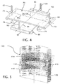
- FIG. 4 depicts a pair of deformable plates 70 and 90 arranged for providing magnification corrections in two orthogonal directions.
- Actuators 80 and 82 which are schematically depicted as arrows, act on opposite ends 72 and 74 of the deformable plate 70 against fulcrums 76 and 78 for generating opposing moments resulting in the bending of the deformable plate 70 about transverse axis 84.
- actuators 100 and 102 act on opposite ends 92 and 94 of the deformable plate 90 against fulcrums 96 and 98 for generating opposing moments resulting in the bending of the deformable plate 90 about transverse axis 94, which extends orthogonal to the transverse axis 84.
- Both axes 84 and 94 preferably extend normal to the optical axes 104 of the deformable plates 70 and 90 as well as the optical axis 24 of the imaging system in which the plates 70 and 90 are mounted.
- the deformable plates 70 and 90 can produce a range of anamorphic magnification adjustments by relatively adjusting the relative magnitude of adjustments contributed by each of the plates 70 and 90 or by adjusting the relative angular positions of their axes 84 and 94.
- a uniform magnification adjustment i.e., a radially symmetric magnification adjustment
- at the substrate 20 can be provided by making equal magnification adjustments with the two plates 70 and 90 about their orthogonal axes 84 and 94.
- one of the two orthogonal axes 84 or 94 over which magnification control is exercised corresponds to an intended direction for stepping or scanning the projection lens 16 across the substrate 20.
- FIG. 5 depicts in cross section a sealed lens barrel 110 for mounting a deformable plate 120 within pressure controlled environment.
- the deformable plate 120 rests on an annular seat 112, which functions similar to the fulcrums of the preceding plate mounting systems, and when seated, divides the sealed lens barrel 110 into two independently controllable pressure chambers 114 and 116.
- An inert gas such as nitrogen, is pumped through respective apertures 1 26 and 128 for adjusting a pressure differential between the two chambers 114 and 116. Higher pressure in the upper chambers 114 pushes the deformable plate 120 against the annular seat 112 and symmetrically deforms the deformable plate 120 for producing a uniform magnification adjustment across the substrate 20.
- a pressure differential is maintained even at a nominal operating condition for the projection lens 16 so that the deformable plate 120 remains deformed in a given direction throughout an intended range of magnification adjustment.
- the deformable plates 40, 70, and 90 of the preceding embodiments are preferably bent into a cylindrical form and the deformable plate 120 is preferably bent into a spherical form for adjusting magnification within either the telecentric object space 36 or the telecentric image space 38 of the projection lens 16 to correct or otherwise adjust magnification while limited unwanted wavefront aberrations or distortions.
- Predictable or measurable departures from the desired cylindrical or spherical forms can be minimized by adjusting the bending forces or compensated for by varying the thickness from the center to the peripheries of the deformable plates or making other adjustments outside the optical zones of the plates for achieving the desired bending performance.
- the deformable plates 40, 70, and 90 can be laterally displaced so that center of curvature of the plates remains centered along the optical axis 24 of the projection lens 16
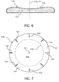
- a deformable plate 130 is depicted in FIG. 6 with radial variation in thickness, which is greatly exaggerated for purposes of illustration.
- An anterior surface 132 of the deformable plate 130 is depicted as flat, but a posterior surface 1 34 of the deformable plate 130 is depicted as having an aspheric surface.
- the variation in thickness is intended to compensate for bending forces that are not distributed so as to otherwise result in a cylindrical or spherical shape for the deformable plate 130. More particularly, the variation in thickness is intended to result in a more nearly cylindrical or spherical shape for the deformable plate 130 in the intended preloaded condition of the deformable plate.
- both of the anterior and posterior surfaces 132 and 134 can be formed with aspheric surfaces so that both surfaces 132 and 134 assume more nearly cylindrical or spherical shapes in the preloaded condition.
- a deformable plate 140 is formed with slots 142 formed in a mounting region 144 of the deformable plate 140, which is outside an optical region 146 of the plate 140 as indicated by an optical boundary line 148. Bending loads for deforming the deformable plate 140 are applied in the mounting region 144 and outside the optical region 146 to avoid interfering with the intended optical performance of the deformable plate. Since the mounting region 144 is not part of the optical system of the projection lens 16 other modifications, including the introduction of the slots 142 or the incorporation of structures for engaging or transmitting forces from the actuator (not shown) can be provided within the mounting region 144.
- the deformable plates exploit telecentric space within projection lenses for adjusting magnification independently of other optical considerations, the deformable plates enable doubly telecentric projection lenses to be adjusted for magnification within a telecentric object space.
- Other components within the projection lenses including reticles and lens elements, which otherwise require adjustment to carry out magnification adjustments can remain fixed.
- the doubly telecentric projections lenses which are equally telecentric in both image and object space, can be designed with more symmetric components to reduce sources of wavefront errors.
- the tolerance for telecentricity is preferably set so that any unwanted distortion accompanying the intended range of magnification adjustments remains within design limits.
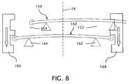
- FIG. 8 illustrates the collective operation of compound deformable plates 1 50 and 160 that are deformable together for producing greater amounts of magnification adjustment or such greater amounts of magnification adjustment with thinner plates.
- actuators 166 and 168 provide for deforming both of the plates 150 and 160 together. Additional deformable plates can be stacked together for making even greater changes to magnification in one or both orthogonal directions.
- each of the fulcrum pairs 152, 1 54, and 162, 164 can represent respective annular seats for supporting the plates 150 and 160 and the actuators 166 and 168 can be parts of a common annular compression ring for engaging the plates 150 and 160 about their respective circumferences.
- the various actuators 50, 52, 80, 82, 100, 102, 114, 116, 166, 168 of the preceding embodiments can be connected to the controller 32 for making continuous, intermittent, or otherwise automatic corrections to magnification associated with the operation of the lithographic projection system 10.
- Control systems for making automatic magnification adjustments are well known.
- sensors (not shown) for monitoring operating conditions of the projection system 10 or the substrate 20 can be arranged to provide information to the controller for predicting responses of the projection system 10 or the substrate 20 requiring magnification adjustments, or other instruments can be used for more directly monitoring the magnification of the projection lens 16, such as by measuring the size of imaged gauge features, to provide the controller 32 with information for controlling the actuators. Continuous closed loop adjustment of magnification is preferred for most lithographic systems.
- the invention is also directly applicable to lithographic projection systems in with the patterns intended for projection are formed by spatial light modulators.
- the deformable plates are locatable adjacent the object or image conjugates, including in the object space adjacent to the output of a microlens array for producing the pattern intended for projection onto a substrate.
- the telecentric image and object space of the telecentric lithographic projection systems gradually transitions into pupil space with distance from the object and image conjugates.
- the deformable plates are located as closely as possible to one or the other of the image conjugates to avoid aberration of the imaging system but benefits of the invention can be obtained by locating the deformable plates elsewhere within primarily image or object space where the instantaneous pupil of a point in the image or object field (i.e., the aperture of the cone of light extending from the field point) is substantially smaller than the clear aperture, and preferably one-fourth or less.
Landscapes
- Physics & Mathematics (AREA)
- General Physics & Mathematics (AREA)
- Optics & Photonics (AREA)
- Exposure And Positioning Against Photoresist Photosensitive Materials (AREA)
- Exposure Of Semiconductors, Excluding Electron Or Ion Beam Exposure (AREA)
- Lenses (AREA)
Applications Claiming Priority (2)
| Application Number | Priority Date | Filing Date | Title |
|---|---|---|---|
| US26317809P | 2009-11-20 | 2009-11-20 | |
| PCT/US2010/056123 WO2011062812A2 (en) | 2009-11-20 | 2010-11-10 | Magnification control for lithographic imaging system |
Publications (2)
| Publication Number | Publication Date |
|---|---|
| EP2502117A2 EP2502117A2 (en) | 2012-09-26 |
| EP2502117B1 true EP2502117B1 (en) | 2016-03-23 |
Family
ID=43824739
Family Applications (1)
| Application Number | Title | Priority Date | Filing Date |
|---|---|---|---|
| EP10779623.7A Active EP2502117B1 (en) | 2009-11-20 | 2010-11-10 | Magnification control for a lithographic imaging system |
Country Status (5)
| Country | Link |
|---|---|
| US (1) | US8922750B2 (enExample) |
| EP (1) | EP2502117B1 (enExample) |
| JP (2) | JP2013511843A (enExample) |
| CN (1) | CN102725696B (enExample) |
| WO (1) | WO2011062812A2 (enExample) |
Families Citing this family (14)
| Publication number | Priority date | Publication date | Assignee | Title |
|---|---|---|---|---|
| US9316838B2 (en) * | 2011-02-04 | 2016-04-19 | Tseng-Lu Chien | LED device has changeable image |
| JP2013195487A (ja) * | 2012-03-16 | 2013-09-30 | Topcon Corp | 露光装置 |
| US9529269B2 (en) | 2012-05-24 | 2016-12-27 | Asml Netherlands B.V. | Lithographic apparatus and device manufacturing method |
| CN103105741B (zh) * | 2013-01-22 | 2015-01-21 | 北京京东方光电科技有限公司 | 对位补偿装置及曝光装置 |
| DE102014209150A1 (de) * | 2014-05-14 | 2015-07-02 | Carl Zeiss Smt Gmbh | Optisches Modul |
| JP6730197B2 (ja) * | 2014-05-14 | 2020-07-29 | カール・ツァイス・エスエムティー・ゲーエムベーハー | ニアフィールドマニピュレータを有する投影露光装置 |
| DE102014209153A1 (de) * | 2014-05-14 | 2015-07-02 | Carl Zeiss Smt Gmbh | Optisches Modul |
| DE102014209151A1 (de) * | 2014-05-14 | 2015-07-02 | Carl Zeiss Smt Gmbh | Optisches Modul |
| DE102014209160A1 (de) * | 2014-05-14 | 2015-11-19 | Carl Zeiss Smt Gmbh | Optisches Modul |
| DE102014209147A1 (de) * | 2014-05-14 | 2015-11-19 | Carl Zeiss Smt Gmbh | Optisches Modul |
| DE102014212710A1 (de) | 2014-07-01 | 2016-01-07 | Carl Zeiss Smt Gmbh | Optischer Manipulator, Projektionsobjektiv und Projektionsbelichtungsanlage |
| DE102019200981B3 (de) | 2019-01-25 | 2020-06-25 | Carl Zeiss Smt Gmbh | Projektionsbelichtungsanlage für die Mikrolithographie |
| KR20240055798A (ko) | 2021-09-01 | 2024-04-29 | 코닝 인코포레이티드 | 변형 가능 렌즈 플레이트를 사용한 배율 조정 가능 투사 시스템 |
| WO2023081041A1 (en) * | 2021-11-02 | 2023-05-11 | Corning Incorporated | Magnification adjustable projection system using movable lens plates |
Family Cites Families (18)
| Publication number | Priority date | Publication date | Assignee | Title |
|---|---|---|---|---|
| JPS59144127A (ja) * | 1983-02-07 | 1984-08-18 | Canon Inc | 像調整された光学装置 |
| JPS61278141A (ja) * | 1985-05-31 | 1986-12-09 | Canon Inc | 投影倍率調整方法 |
| US4769680A (en) * | 1987-10-22 | 1988-09-06 | Mrs Technology, Inc. | Apparatus and method for making large area electronic devices, such as flat panel displays and the like, using correlated, aligned dual optical systems |
| US5995263A (en) * | 1993-11-12 | 1999-11-30 | Nikon Corporation | Projection exposure apparatus |
| JPH08124831A (ja) * | 1994-10-25 | 1996-05-17 | Toshiba Corp | 倍率補正装置及びこれを適用した露光装置 |
| US5557469A (en) * | 1994-10-28 | 1996-09-17 | Ultratech Stepper, Inc. | Beamsplitter in single fold optical system and optical variable magnification method and system |
| JPH10133150A (ja) * | 1996-10-29 | 1998-05-22 | Canon Inc | 回折光学装置及びこれを用いた露光装置 |
| US6043863A (en) * | 1996-11-14 | 2000-03-28 | Nikon Corporation | Holder for reflecting member and exposure apparatus having the same |
| JP3352354B2 (ja) * | 1997-04-28 | 2002-12-03 | キヤノン株式会社 | 露光装置およびデバイス製造方法 |
| JPH113856A (ja) * | 1997-06-11 | 1999-01-06 | Canon Inc | 投影露光方法及び投影露光装置 |
| JP2000199850A (ja) * | 1999-01-07 | 2000-07-18 | Nikon Corp | 投影光学系及び投影露光装置並びにデバイスの製造方法 |
| JP2003222795A (ja) * | 2001-11-21 | 2003-08-08 | Adtec Engineeng Co Ltd | 倍率補正光学系 |
| TWI267708B (en) * | 2001-11-21 | 2006-12-01 | Adtec Eng Co Ltd | Optical magnification adjustment system and projection exposure device |
| CN100526986C (zh) * | 2001-11-21 | 2009-08-12 | 株式会社阿迪泰克工程 | 光学投影曝光设备 |
| JP2003223003A (ja) * | 2001-11-22 | 2003-08-08 | Adtec Engineeng Co Ltd | 露光装置 |
| JP4368639B2 (ja) * | 2003-08-19 | 2009-11-18 | 株式会社アドテックエンジニアリング | 投影露光装置 |
| JP4195674B2 (ja) | 2004-03-31 | 2008-12-10 | 株式会社オーク製作所 | 投影光学系および投影露光装置 |
| EP1835527A4 (en) | 2004-12-16 | 2011-01-05 | Nikon Corp | OPTICAL PROJECTION SYSTEM, APPARATUS, SYSTEM AND EXPOSURE METHOD |
-
2010
- 2010-10-20 US US12/908,392 patent/US8922750B2/en active Active
- 2010-11-10 WO PCT/US2010/056123 patent/WO2011062812A2/en not_active Ceased
- 2010-11-10 JP JP2012539944A patent/JP2013511843A/ja active Pending
- 2010-11-10 CN CN201080052464.7A patent/CN102725696B/zh active Active
- 2010-11-10 EP EP10779623.7A patent/EP2502117B1/en active Active
-
2015
- 2015-05-07 JP JP2015094783A patent/JP2015180945A/ja active Pending
Also Published As
| Publication number | Publication date |
|---|---|
| US20110122383A1 (en) | 2011-05-26 |
| JP2013511843A (ja) | 2013-04-04 |
| CN102725696B (zh) | 2014-12-10 |
| EP2502117A2 (en) | 2012-09-26 |
| US8922750B2 (en) | 2014-12-30 |
| CN102725696A (zh) | 2012-10-10 |
| WO2011062812A3 (en) | 2011-07-14 |
| JP2015180945A (ja) | 2015-10-15 |
| WO2011062812A2 (en) | 2011-05-26 |
Similar Documents
| Publication | Publication Date | Title |
|---|---|---|
| EP2502117B1 (en) | Magnification control for a lithographic imaging system | |
| JP2013511843A5 (enExample) | ||
| CN102077143B (zh) | 用于显微光刻投影系统的远心性校正器 | |
| US9213245B2 (en) | Optical system and multi facet mirror of a microlithographic projection exposure apparatus | |
| KR100791161B1 (ko) | 광학장치 및 그것을 구비한 노광장치 | |
| CN101932975B (zh) | 照明光学部件与投射曝光设备 | |
| US7139137B2 (en) | Support mechanism, exposure apparatus having the same, and aberration reducing method | |
| KR20100087325A (ko) | 조명 광학 시스템, 노광 장치 및 디바이스 제조 방법 | |
| CN1603961A (zh) | 光刻装置和器件制造方法 | |
| US8854605B2 (en) | Illumination optical system, exposure apparatus, and device fabrication method | |
| US7385672B2 (en) | Exposure apparatus and method | |
| WO1999018604A1 (en) | Projection exposure method and apparatus | |
| JP4147574B2 (ja) | 波面収差計測方法、投影光学系の調整方法及び露光方法、並びに露光装置の製造方法 | |
| US7522260B1 (en) | Method for correcting astigmatism in a microlithography projection exposure apparatus, a projection objective of such a projection exposure apparatus, and a fabrication method for micropatterned components | |
| KR100945605B1 (ko) | 노광장치 및 디바이스 제조방법 | |
| US12078936B2 (en) | Magnification adjustable projection system using deformable lens plates | |
| JP2003045795A (ja) | 光学特性計測方法、投影光学系の調整方法及び露光方法、並びに露光装置の製造方法 | |
| CN1825211A (zh) | 光刻装置和器件制造方法 |
Legal Events
| Date | Code | Title | Description |
|---|---|---|---|
| PUAI | Public reference made under article 153(3) epc to a published international application that has entered the european phase |
Free format text: ORIGINAL CODE: 0009012 |
|
| 17P | Request for examination filed |
Effective date: 20120614 |
|
| AK | Designated contracting states |
Kind code of ref document: A2 Designated state(s): AL AT BE BG CH CY CZ DE DK EE ES FI FR GB GR HR HU IE IS IT LI LT LU LV MC MK MT NL NO PL PT RO RS SE SI SK SM TR |
|
| DAX | Request for extension of the european patent (deleted) | ||
| 17Q | First examination report despatched |
Effective date: 20130813 |
|
| REG | Reference to a national code |
Ref country code: DE Ref legal event code: R079 Ref document number: 602010031462 Country of ref document: DE Free format text: PREVIOUS MAIN CLASS: G03F0007200000 Ipc: G02B0027000000 |
|
| GRAP | Despatch of communication of intention to grant a patent |
Free format text: ORIGINAL CODE: EPIDOSNIGR1 |
|
| RIC1 | Information provided on ipc code assigned before grant |
Ipc: G02B 15/00 20060101ALI20150817BHEP Ipc: G03F 7/20 20060101ALI20150817BHEP Ipc: G02B 27/00 20060101AFI20150817BHEP |
|
| INTG | Intention to grant announced |
Effective date: 20150918 |
|
| GRAS | Grant fee paid |
Free format text: ORIGINAL CODE: EPIDOSNIGR3 |
|
| GRAA | (expected) grant |
Free format text: ORIGINAL CODE: 0009210 |
|
| AK | Designated contracting states |
Kind code of ref document: B1 Designated state(s): AL AT BE BG CH CY CZ DE DK EE ES FI FR GB GR HR HU IE IS IT LI LT LU LV MC MK MT NL NO PL PT RO RS SE SI SK SM TR |
|
| REG | Reference to a national code |
Ref country code: GB Ref legal event code: FG4D |
|
| REG | Reference to a national code |
Ref country code: CH Ref legal event code: EP |
|
| REG | Reference to a national code |
Ref country code: AT Ref legal event code: REF Ref document number: 783717 Country of ref document: AT Kind code of ref document: T Effective date: 20160415 |
|
| REG | Reference to a national code |
Ref country code: IE Ref legal event code: FG4D |
|
| REG | Reference to a national code |
Ref country code: DE Ref legal event code: R096 Ref document number: 602010031462 Country of ref document: DE |
|
| REG | Reference to a national code |
Ref country code: LT Ref legal event code: MG4D |
|
| REG | Reference to a national code |
Ref country code: NL Ref legal event code: MP Effective date: 20160323 |
|
| PG25 | Lapsed in a contracting state [announced via postgrant information from national office to epo] |
Ref country code: FI Free format text: LAPSE BECAUSE OF FAILURE TO SUBMIT A TRANSLATION OF THE DESCRIPTION OR TO PAY THE FEE WITHIN THE PRESCRIBED TIME-LIMIT Effective date: 20160323 Ref country code: GR Free format text: LAPSE BECAUSE OF FAILURE TO SUBMIT A TRANSLATION OF THE DESCRIPTION OR TO PAY THE FEE WITHIN THE PRESCRIBED TIME-LIMIT Effective date: 20160624 Ref country code: NO Free format text: LAPSE BECAUSE OF FAILURE TO SUBMIT A TRANSLATION OF THE DESCRIPTION OR TO PAY THE FEE WITHIN THE PRESCRIBED TIME-LIMIT Effective date: 20160623 Ref country code: HR Free format text: LAPSE BECAUSE OF FAILURE TO SUBMIT A TRANSLATION OF THE DESCRIPTION OR TO PAY THE FEE WITHIN THE PRESCRIBED TIME-LIMIT Effective date: 20160323 |
|
| REG | Reference to a national code |
Ref country code: AT Ref legal event code: MK05 Ref document number: 783717 Country of ref document: AT Kind code of ref document: T Effective date: 20160323 |
|
| PG25 | Lapsed in a contracting state [announced via postgrant information from national office to epo] |
Ref country code: NL Free format text: LAPSE BECAUSE OF FAILURE TO SUBMIT A TRANSLATION OF THE DESCRIPTION OR TO PAY THE FEE WITHIN THE PRESCRIBED TIME-LIMIT Effective date: 20160323 Ref country code: LT Free format text: LAPSE BECAUSE OF FAILURE TO SUBMIT A TRANSLATION OF THE DESCRIPTION OR TO PAY THE FEE WITHIN THE PRESCRIBED TIME-LIMIT Effective date: 20160323 Ref country code: LV Free format text: LAPSE BECAUSE OF FAILURE TO SUBMIT A TRANSLATION OF THE DESCRIPTION OR TO PAY THE FEE WITHIN THE PRESCRIBED TIME-LIMIT Effective date: 20160323 Ref country code: SE Free format text: LAPSE BECAUSE OF FAILURE TO SUBMIT A TRANSLATION OF THE DESCRIPTION OR TO PAY THE FEE WITHIN THE PRESCRIBED TIME-LIMIT Effective date: 20160323 Ref country code: RS Free format text: LAPSE BECAUSE OF FAILURE TO SUBMIT A TRANSLATION OF THE DESCRIPTION OR TO PAY THE FEE WITHIN THE PRESCRIBED TIME-LIMIT Effective date: 20160323 |
|
| PG25 | Lapsed in a contracting state [announced via postgrant information from national office to epo] |
Ref country code: IS Free format text: LAPSE BECAUSE OF FAILURE TO SUBMIT A TRANSLATION OF THE DESCRIPTION OR TO PAY THE FEE WITHIN THE PRESCRIBED TIME-LIMIT Effective date: 20160723 Ref country code: PL Free format text: LAPSE BECAUSE OF FAILURE TO SUBMIT A TRANSLATION OF THE DESCRIPTION OR TO PAY THE FEE WITHIN THE PRESCRIBED TIME-LIMIT Effective date: 20160323 Ref country code: EE Free format text: LAPSE BECAUSE OF FAILURE TO SUBMIT A TRANSLATION OF THE DESCRIPTION OR TO PAY THE FEE WITHIN THE PRESCRIBED TIME-LIMIT Effective date: 20160323 |
|
| REG | Reference to a national code |
Ref country code: FR Ref legal event code: PLFP Year of fee payment: 7 |
|
| PG25 | Lapsed in a contracting state [announced via postgrant information from national office to epo] |
Ref country code: CZ Free format text: LAPSE BECAUSE OF FAILURE TO SUBMIT A TRANSLATION OF THE DESCRIPTION OR TO PAY THE FEE WITHIN THE PRESCRIBED TIME-LIMIT Effective date: 20160323 Ref country code: AT Free format text: LAPSE BECAUSE OF FAILURE TO SUBMIT A TRANSLATION OF THE DESCRIPTION OR TO PAY THE FEE WITHIN THE PRESCRIBED TIME-LIMIT Effective date: 20160323 Ref country code: RO Free format text: LAPSE BECAUSE OF FAILURE TO SUBMIT A TRANSLATION OF THE DESCRIPTION OR TO PAY THE FEE WITHIN THE PRESCRIBED TIME-LIMIT Effective date: 20160323 Ref country code: ES Free format text: LAPSE BECAUSE OF FAILURE TO SUBMIT A TRANSLATION OF THE DESCRIPTION OR TO PAY THE FEE WITHIN THE PRESCRIBED TIME-LIMIT Effective date: 20160323 Ref country code: SM Free format text: LAPSE BECAUSE OF FAILURE TO SUBMIT A TRANSLATION OF THE DESCRIPTION OR TO PAY THE FEE WITHIN THE PRESCRIBED TIME-LIMIT Effective date: 20160323 Ref country code: SK Free format text: LAPSE BECAUSE OF FAILURE TO SUBMIT A TRANSLATION OF THE DESCRIPTION OR TO PAY THE FEE WITHIN THE PRESCRIBED TIME-LIMIT Effective date: 20160323 Ref country code: PT Free format text: LAPSE BECAUSE OF FAILURE TO SUBMIT A TRANSLATION OF THE DESCRIPTION OR TO PAY THE FEE WITHIN THE PRESCRIBED TIME-LIMIT Effective date: 20160725 |
|
| PG25 | Lapsed in a contracting state [announced via postgrant information from national office to epo] |
Ref country code: IT Free format text: LAPSE BECAUSE OF FAILURE TO SUBMIT A TRANSLATION OF THE DESCRIPTION OR TO PAY THE FEE WITHIN THE PRESCRIBED TIME-LIMIT Effective date: 20160323 Ref country code: BE Free format text: LAPSE BECAUSE OF FAILURE TO SUBMIT A TRANSLATION OF THE DESCRIPTION OR TO PAY THE FEE WITHIN THE PRESCRIBED TIME-LIMIT Effective date: 20160323 |
|
| REG | Reference to a national code |
Ref country code: DE Ref legal event code: R097 Ref document number: 602010031462 Country of ref document: DE |
|
| PLBE | No opposition filed within time limit |
Free format text: ORIGINAL CODE: 0009261 |
|
| STAA | Information on the status of an ep patent application or granted ep patent |
Free format text: STATUS: NO OPPOSITION FILED WITHIN TIME LIMIT |
|
| PG25 | Lapsed in a contracting state [announced via postgrant information from national office to epo] |
Ref country code: DK Free format text: LAPSE BECAUSE OF FAILURE TO SUBMIT A TRANSLATION OF THE DESCRIPTION OR TO PAY THE FEE WITHIN THE PRESCRIBED TIME-LIMIT Effective date: 20160323 |
|
| PG25 | Lapsed in a contracting state [announced via postgrant information from national office to epo] |
Ref country code: BG Free format text: LAPSE BECAUSE OF FAILURE TO SUBMIT A TRANSLATION OF THE DESCRIPTION OR TO PAY THE FEE WITHIN THE PRESCRIBED TIME-LIMIT Effective date: 20160623 |
|
| 26N | No opposition filed |
Effective date: 20170102 |
|
| PG25 | Lapsed in a contracting state [announced via postgrant information from national office to epo] |
Ref country code: SI Free format text: LAPSE BECAUSE OF FAILURE TO SUBMIT A TRANSLATION OF THE DESCRIPTION OR TO PAY THE FEE WITHIN THE PRESCRIBED TIME-LIMIT Effective date: 20160323 |
|
| REG | Reference to a national code |
Ref country code: CH Ref legal event code: PL |
|
| PG25 | Lapsed in a contracting state [announced via postgrant information from national office to epo] |
Ref country code: CH Free format text: LAPSE BECAUSE OF NON-PAYMENT OF DUE FEES Effective date: 20161130 Ref country code: LI Free format text: LAPSE BECAUSE OF NON-PAYMENT OF DUE FEES Effective date: 20161130 |
|
| REG | Reference to a national code |
Ref country code: IE Ref legal event code: MM4A |
|
| PG25 | Lapsed in a contracting state [announced via postgrant information from national office to epo] |
Ref country code: LU Free format text: LAPSE BECAUSE OF NON-PAYMENT OF DUE FEES Effective date: 20161130 |
|
| REG | Reference to a national code |
Ref country code: FR Ref legal event code: PLFP Year of fee payment: 8 |
|
| PG25 | Lapsed in a contracting state [announced via postgrant information from national office to epo] |
Ref country code: IE Free format text: LAPSE BECAUSE OF NON-PAYMENT OF DUE FEES Effective date: 20161110 |
|
| PG25 | Lapsed in a contracting state [announced via postgrant information from national office to epo] |
Ref country code: HU Free format text: LAPSE BECAUSE OF FAILURE TO SUBMIT A TRANSLATION OF THE DESCRIPTION OR TO PAY THE FEE WITHIN THE PRESCRIBED TIME-LIMIT; INVALID AB INITIO Effective date: 20101110 Ref country code: CY Free format text: LAPSE BECAUSE OF FAILURE TO SUBMIT A TRANSLATION OF THE DESCRIPTION OR TO PAY THE FEE WITHIN THE PRESCRIBED TIME-LIMIT Effective date: 20160323 |
|
| PG25 | Lapsed in a contracting state [announced via postgrant information from national office to epo] |
Ref country code: MK Free format text: LAPSE BECAUSE OF FAILURE TO SUBMIT A TRANSLATION OF THE DESCRIPTION OR TO PAY THE FEE WITHIN THE PRESCRIBED TIME-LIMIT Effective date: 20160323 Ref country code: TR Free format text: LAPSE BECAUSE OF FAILURE TO SUBMIT A TRANSLATION OF THE DESCRIPTION OR TO PAY THE FEE WITHIN THE PRESCRIBED TIME-LIMIT Effective date: 20160323 Ref country code: MC Free format text: LAPSE BECAUSE OF FAILURE TO SUBMIT A TRANSLATION OF THE DESCRIPTION OR TO PAY THE FEE WITHIN THE PRESCRIBED TIME-LIMIT Effective date: 20160323 |
|
| PG25 | Lapsed in a contracting state [announced via postgrant information from national office to epo] |
Ref country code: MT Free format text: LAPSE BECAUSE OF NON-PAYMENT OF DUE FEES Effective date: 20161110 |
|
| REG | Reference to a national code |
Ref country code: FR Ref legal event code: PLFP Year of fee payment: 9 |
|
| PG25 | Lapsed in a contracting state [announced via postgrant information from national office to epo] |
Ref country code: AL Free format text: LAPSE BECAUSE OF FAILURE TO SUBMIT A TRANSLATION OF THE DESCRIPTION OR TO PAY THE FEE WITHIN THE PRESCRIBED TIME-LIMIT Effective date: 20160323 |
|
| PGFP | Annual fee paid to national office [announced via postgrant information from national office to epo] |
Ref country code: FR Payment date: 20191029 Year of fee payment: 10 |
|
| PGFP | Annual fee paid to national office [announced via postgrant information from national office to epo] |
Ref country code: GB Payment date: 20191029 Year of fee payment: 10 |
|
| GBPC | Gb: european patent ceased through non-payment of renewal fee |
Effective date: 20201110 |
|
| PG25 | Lapsed in a contracting state [announced via postgrant information from national office to epo] |
Ref country code: FR Free format text: LAPSE BECAUSE OF NON-PAYMENT OF DUE FEES Effective date: 20201130 |
|
| PG25 | Lapsed in a contracting state [announced via postgrant information from national office to epo] |
Ref country code: GB Free format text: LAPSE BECAUSE OF NON-PAYMENT OF DUE FEES Effective date: 20201110 |
|
| P01 | Opt-out of the competence of the unified patent court (upc) registered |
Effective date: 20230527 |
|
| PGFP | Annual fee paid to national office [announced via postgrant information from national office to epo] |
Ref country code: DE Payment date: 20241010 Year of fee payment: 15 |