EP2501590B1 - Wischblatt in flachbalkenbauweise - Google Patents
Wischblatt in flachbalkenbauweise Download PDFInfo
- Publication number
- EP2501590B1 EP2501590B1 EP10773012.9A EP10773012A EP2501590B1 EP 2501590 B1 EP2501590 B1 EP 2501590B1 EP 10773012 A EP10773012 A EP 10773012A EP 2501590 B1 EP2501590 B1 EP 2501590B1
- Authority
- EP
- European Patent Office
- Prior art keywords
- side walls
- wiper blade
- fixing element
- connecting element
- fixing
- Prior art date
- Legal status (The legal status is an assumption and is not a legal conclusion. Google has not performed a legal analysis and makes no representation as to the accuracy of the status listed.)
- Active
Links
- 238000010276 construction Methods 0.000 title claims description 3
- 239000002184 metal Substances 0.000 claims description 8
- 239000000463 material Substances 0.000 description 2
- 238000004026 adhesive bonding Methods 0.000 description 1
- 238000005452 bending Methods 0.000 description 1
- 238000007596 consolidation process Methods 0.000 description 1
- 238000004519 manufacturing process Methods 0.000 description 1
- 238000000034 method Methods 0.000 description 1
- 238000003825 pressing Methods 0.000 description 1
- 238000005476 soldering Methods 0.000 description 1
- 230000008719 thickening Effects 0.000 description 1
- 238000003466 welding Methods 0.000 description 1
Images

Classifications
-
- B—PERFORMING OPERATIONS; TRANSPORTING
- B60—VEHICLES IN GENERAL
- B60S—SERVICING, CLEANING, REPAIRING, SUPPORTING, LIFTING, OR MANOEUVRING OF VEHICLES, NOT OTHERWISE PROVIDED FOR
- B60S1/00—Cleaning of vehicles
- B60S1/02—Cleaning windscreens, windows or optical devices
- B60S1/04—Wipers or the like, e.g. scrapers
- B60S1/32—Wipers or the like, e.g. scrapers characterised by constructional features of wiper blade arms or blades
- B60S1/38—Wiper blades
- B60S1/3848—Flat-type wiper blade, i.e. without harness
- B60S1/3849—Connectors therefor; Connection to wiper arm; Attached to blade
- B60S1/3851—Mounting of connector to blade assembly
- B60S1/3858—Mounting of connector to blade assembly with protrusions cooperating with holes
-
- B—PERFORMING OPERATIONS; TRANSPORTING
- B60—VEHICLES IN GENERAL
- B60S—SERVICING, CLEANING, REPAIRING, SUPPORTING, LIFTING, OR MANOEUVRING OF VEHICLES, NOT OTHERWISE PROVIDED FOR
- B60S1/00—Cleaning of vehicles
- B60S1/02—Cleaning windscreens, windows or optical devices
- B60S1/04—Wipers or the like, e.g. scrapers
- B60S1/32—Wipers or the like, e.g. scrapers characterised by constructional features of wiper blade arms or blades
- B60S1/38—Wiper blades
- B60S1/3848—Flat-type wiper blade, i.e. without harness
- B60S1/3849—Connectors therefor; Connection to wiper arm; Attached to blade
- B60S1/387—Connectors therefor; Connection to wiper arm; Attached to blade the connector being suitable for receiving different types of adapter
-
- B—PERFORMING OPERATIONS; TRANSPORTING
- B60—VEHICLES IN GENERAL
- B60S—SERVICING, CLEANING, REPAIRING, SUPPORTING, LIFTING, OR MANOEUVRING OF VEHICLES, NOT OTHERWISE PROVIDED FOR
- B60S1/00—Cleaning of vehicles
- B60S1/02—Cleaning windscreens, windows or optical devices
- B60S1/04—Wipers or the like, e.g. scrapers
- B60S1/32—Wipers or the like, e.g. scrapers characterised by constructional features of wiper blade arms or blades
- B60S1/40—Connections between blades and arms
- B60S2001/4093—Connections between blades and arms characterised by the mounting of the pivot on the main yoke of the blade
Definitions
- the invention is based on a wiper blade in flat bar construction according to the preamble of claim 1.
- a generic wiper blade in which in the central region a connection element made of a suitable material, for example made of plastic, is mounted on two parallel spring rails, which serve as a support element.
- the connecting element has on the long sides guide profiles with which it includes the spring rails from the outer longitudinal sides of the top and bottom and on the long sides themselves.
- a fixing element which supports itself on the connecting element is provided which fixes the spring rails positively and / or non-positively.
- a pin is provided, which is guided approximately perpendicular to the broad side of the spring rails in a bore of the connection element and presses the spring rails outwardly frictionally against the guide profiles of the connection element.
- the pin can also engage in recesses on the inner sides of the spring rails, which in addition to or instead of the frictional connection a positive connection is achieved.
- the positive connection can also be reinforced by the fact that recesses are also provided on the outer sides of the spring rails, engage in the projections in the region of the guide profile.
- the fixing pin is secured in its axial position during assembly in its guide, for example by a press fit, by gluing, soldering, welding, caulking, pressing, screwing or the like., In its axial position.
- the fixing element of the generic wiper blade has a U-shaped cross-sectional profile with two interconnected by a bottom side walls, which are recessed in niches on the inner sides of the side walls of the connection element, wherein the bottom of the fixing parallel to the bottom of the connection element and in Extension of the side walls of the fixing element to the spring rail are connected to the side walls tabs which engage through openings in the bottom of the connecting element in the recesses of the spring rail.
- the wiper blade according to the invention with the connecting element and its fixing element forms a simple plug-in system, in which the assembly can be carried out by simple handles in a short time. Furthermore, the simplified assembly reduces the risk of incorrect assembly.
- the fixing itself is a dimensionally stable component that transmits the forces acting on it over a large area and backlash on the connection element. The relevant for the wear surface pressures are very low. It can therefore take on additional functions, e.g. It can accommodate bearing elements for the articulated connection with a wiper arm.
- the fixing advantageously has holes in its side walls, which serve as a hub or for receiving a hinge axis.
- connection element has recesses in the region of the outwardly projecting rivet heads into which the rivet heads engage during assembly.
- the fixing element In order to anchor the fixing element in the connecting element, it is approximately free of play clipped into the niches of the connection element or from the open sides of the niche, which are facing away from the wiper strip, inserted and latched by locking lugs in the niches of the side walls, in latching openings of the side walls of the fixing engage during assembly.
- connection element and the fixing element can be made of plastic.
- the fixing element is made of metal in order to achieve greater strength, stability and service life. As a result, good lateral guidance and high wiping quality are ensured over the service life of the wiper blade.
- the fixing element made of metal is combined with a connecting element made of plastic.
- the fixing element is expediently a bent sheet metal part, wherein the tabs are notched out of the ground and bent into the planes of the side walls. This results in the bottom of the fixing a breakthrough, which corresponds to the notched tabs.
- a wiper blade 10 essentially has a wiper strip 12, the back strip 14 of which is held by two spring rails 16, which engage as support elements below the back strip 14 in longitudinal grooves (not shown) of the wiper strip 12.
- a spring rail 16 which is usually housed in a longitudinal channel of the wiper strip 12.
- a connecting element 20 is mounted on the spring rails 16, which serves for the articulated connection of the wiper blade 10 with a wiper arm, not shown.
- connection element 20 has two side walls 22 which have guide profiles 28 towards the spring rails 16. These include in the assembled state, the spring rails 16 laterally from below and from above.
- the two side walls 22 of the connecting element 20 are connected to each other above the guide profiles 28 by a bottom 24. This has the wiper strip 12 towards a longitudinal groove 26, which provides the back strip 14 sufficient space.
- niches 30 are provided, which are open to the side facing away from the wiper strip 12 side, and having latching lugs 32 on their inner sides.
- a fixing member 40 When mounting in the mounting direction 54 of the open sides of the niches 30, a fixing member 40 is used, the side walls 42 are connected by a bottom 44 with each other. The side walls 42 are guided in the recesses 30 of the connecting element 20 almost free of play.
- tabs 52 are integrally formed on the side walls, which are guided through openings 38 in the bottom 24 of the connection element 20 and engage in recesses 18, which are arranged opposite one another on the outer sides of the spring rails 16.
- the mounting position of the connection element 20 is defined. It is possible that a plurality of recesses 18 are provided offset in the longitudinal direction, so that different mounting positions of the connection element 20 are possible in the same wiper blade 10 according to application. In order to ensure the stability of the side walls 22 in the region of the recesses 30, the side walls 22 are reinforced in this area by thickenings 36.
- the fixing member 40 has in its side walls latching openings 50 which cooperate with the latching lugs 32 in the recesses 30 of the side walls 22 of the connection element 20, so that the fixing element 40 is latched to the connection element 20 in the mounted position.
- the connection element 20 is fixed by the guide profiles 28 in the direction of a vertical axis and transversely to the longitudinal direction of the wiper blade 10, while the fixing element 40 takes over the securing of the connection element 20 in the longitudinal direction of the wiper blade 10.
- the fixing element 40 can take on additional functions, for example, it can receive bearing elements for the articulated connection with the wiper arm.
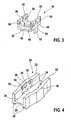
- the fixing element 40 in its side walls 42 holes 46 which can serve as hubs for a hinge connection or in which a hinge axis 48 is attached. This is expediently with the side walls 42nd riveted, wherein the outwardly projecting rivet heads 58 find in recesses 34 of the niches 30 of the connection element 20 space.
- the fixing element 40 can consist of any suitable material.
- the fixing element 40 is a metal part. This may be a sheet metal part, a Zamakteil, Magnesiumdruckgussteil or a wireform.
- the sheet metal part is expediently produced in a punch bending process, wherein the tabs are notched out of the ground and bent into the planes of the side walls 42. The resulting breakthrough in the bottom 44 is designated 56.
Description
- Die Erfindung geht von einem Wischblatt in Flachbalkenbauweise nach dem Oberbegriff des Anspruchs 1 aus.
- Aus der
DE 100 58 208 A1 ist ein gattungsgemäßes Wischblatt bekannt, bei dem im mittleren Bereich ein Anschlusselement aus einem geeigneten Werkstoff, z.B. aus Kunststoff, auf zwei parallel verlaufenden Federschienen befestigt ist, die als Tragelement dienen. Das Anschlusselement besitzt an den Längsseiten Führungsprofile, mit denen es die Federschienen von den äußeren Längsseiten aus oben und unten sowie an den Längsseiten selbst umfasst. Zwischen den beiden Federschienen ist ein sich an dem Verbindungselement abstützendes Fixierelement vorhanden, das die Federschienen form- und/oder kraftschlüssig fixiert. Als Fixierelement ist ein Stift vorgesehen, der etwa senkrecht zur Breitseite der Federschienen in einer Bohrung des Anschlusselements geführt ist und die Federschienen nach außen kraftschlüssig gegen die Führungsprofile des Anschlusselements drückt. Bei einigen Ausgestaltungen kann der Stift auch in Aussparungen an den Innenseiten der Federschienen eingreifen, wodurch zusätzlich oder anstelle des Kraftschlusses ein Formschluss erzielt wird. Der Formschluss kann zudem dadurch verstärkt werden, dass an den Außenseiten der Federschienen ebenfalls Aussparungen vorgesehen sind, in die Überstände im Bereich des Führungsprofils eingreifen. Der Fixierstift wird bei der Montage in seiner Führung, z.B. durch eine Presspassung, durch Kleben, Löten, Verschweißen, Verstemmen, Verpressen, Verschrauben oder dgl., in seiner axialen Lage gesichert. - Erfindungsgemäß ist ein Wischblatt mit der Merkmalen des Anspruchs 1 vorgesehen. Nach der Erfindung weist das Fixierelement des gattungsgemäßen Wischblattes ein u-förmiges Querschnittprofil mit zwei durch einen Boden miteinander verbundenen Seitenwänden auf, die in Nischen an den Innenseiten der Seitenwände des Anschlusselements eingelassen sind, wobei der Boden des Fixierelements parallel zum Boden des Anschlusselements verläuft und in Verlängerung der Seitenwände des Fixierelements auf die Federschiene zu mit den Seitenwänden Laschen verbunden sind, die durch Öffnungen im Boden des Anschlusselements in die Aussparungen der Federschiene eingreifen.
- Das erfindungsgemäße Wischblatt mit dem Anschlusselement und dessen Fixierelement bildet ein einfaches Stecksystem, bei dem die Montage durch einfache Handgriffe in kurzer Zeit durchgeführt werden kann. Ferner wird durch die vereinfachte Montage das Risiko von Fehlmontagen gesenkt. Das Fixierelement selbst ist ein formstabiles Bauelement, das die auf ihn einwirkenden Kräfte großflächig und spielfrei auf das Anschlusselement überträgt. Die für den Verschleiß relevanten Flächenpressungen sind sehr gering. Es kann daher weitere Funktionen übernehmen, z.B. kann es Lagerelemente für die Gelenkverbindung mit einem Wischarm aufnehmen. Hierzu weist das Fixierelement vorteilhafterweise in seinen Seitenwänden Bohrungen auf, die als Nabe oder zur Aufnahme einer Gelenkachse dienen. Wird die Gelenkachse in den Seitenwänden des Fixierelements eingenietet, weist das Anschlusselement im Bereich der nach außen vorstehenden Nietköpfe Aussparungen auf, in die die Nietköpfe bei der Montage eingreifen. Um das Fixierelement im Anschlusselement zu verankern, wird es annähernd spielfrei in die Nischen des Anschlusselements eingeklippst oder von offenen Seiten der Nische, die von der Wischleiste abgewandt liegen, eingesetzt und durch Rastnasen in den Nischen der Seitenwände verrastet, die in Rastöffnungen der Seitenwände des Fixierelements bei der Montage einrasten.
- Grundsätzlich können das Anschlusselement und das Fixierelement aus Kunststoff hergestellt werden. Zweckmäßigerweise wird das Fixierelement allerdings aus Metall gefertigt, um eine größere Festigkeit, Stabilität und Lebensdauer zu erzielen. Dadurch wird über die Lebensdauer des Wischblatts eine gute Seitenführung und hohe Wischqualität gewährleistet. In vorteilhafter Weise wird das Fixierelement aus Metall mit einem Anschlusselement aus Kunststoff kombiniert.
- Dabei ist das Fixierelement zweckmäßigerweise ein Blechbiegeteil, wobei die Laschen aus dem Boden ausgeklinkt und in die Ebenen der Seitenwände gebogen sind. Dabei entsteht in dem Boden des Fixierelements ein Durchbruch, der den ausgeklinkten Laschen entspricht.
- Weitere Vorteile ergeben sich aus der folgenden Zeichnungsbeschreibung. In der Zeichnung ist ein Ausführungsbeispiel der Erfindung dargestellt. Die Zeichnung, die Beschreibung und die Ansprüche enthalten zahlreiche Merkmale in Kombination. Der Fachmann wird die Merkmale zweckmäßigerweise auch einzeln betrachten und zu sinnvollen weiteren Kombinationen zusammenfassen.
- Es zeigen:
-
Fig. 1 eine perspektivische Teilansicht eines erfindungsgemäßen Wischblatts mit einem Anschlusselement während der Montage eines Fixierelements, -
Fig. 2 eine perspektivische, teilweise geschnittene Teilansicht eines Wischblatts nachFig. 1 mit einem montierten Fixierelement, -
Fig. 3 eine perspektivische Ansicht eines Fixierelements und -
Fig. 4 eine perspektivische Ansicht eines Anschlusselements. - Ein Wischblatt 10 besitzt im Wesentlichen eine Wischleiste 12, deren Rückenleiste 14 von zwei Federschienen 16 gehalten wird, die als Tragelement unterhalb der Rückenleiste 14 in nicht näher dargestellte Längsnuten der Wischleiste 12 eingreifen. Es sind auch Lösungen mit einer Federschiene 16 möglich, die in der Regel in einem Längskanal der Wischleiste 12 untergebracht ist. Im mittleren Bereich des Wischblatts 10 ist auf den Federschienen 16 ein Anschlusselement 20 befestigt, das zur gelenkigen Verbindung des Wischblatts 10 mit einem nicht dargestellten Wischarm dient.
- Das Anschlusselement 20 besitzt zwei Seitenwände 22, die zu den Federschienen 16 hin Führungsprofile 28 besitzen. Diese umfassen in montiertem Zustand die Federschienen 16 seitlich von unten und von oben. Die beiden Seitenwände 22 des Anschlusselements 20 sind oberhalb der Führungsprofile 28 durch einen Boden 24 miteinander verbunden. Dieser weist zur Wischleiste 12 hin eine Längsnut 26 auf, die der Rückenleiste 14 ausreichend Platz bietet.
- An den Innenseiten der Seitenwände 22 des Anschlusselements 20 sind Nischen 30 vorgesehen, die zu der von der Wischleiste 12 abgewandten Seite hin offen sind, und die an ihren Innenseiten Rastnasen 32 aufweisen. Bei der Montage in Montagerichtung 54 wird von den offenen Seiten der Nischen 30 ein Fixierelement 40 eingesetzt, dessen Seitenwände 42 durch einen Boden 44 miteinander verbunden sind. Die Seitenwände 42 sind in den Nischen 30 des Anschlusselements 20 nahezu spielfrei geführt. In Verlängerung der Seitenwände 42 auf die Federschienen 16 zu sind an den Seitenwänden 42 Laschen 52 angeformt, die durch Öffnungen 38 im Boden 24 des Anschlusselements 20 geführt sind und in Aussparungen 18 eingreifen, die an den Außenseiten der Federschienen 16 einander gegenüberliegend angeordnet sind. Durch die Aussparungen 18 wird die Montageposition des Anschlusselements 20 definiert. Dabei ist es möglich, dass mehrere Aussparungen 18 in Längsrichtung versetzt vorgesehen sind, sodass bei dem gleichen Wischblatt 10 nach Anwendungsfall verschiedene Montagepositionen des Anschlusselements 20 möglich sind. Um die Stabilität der Seitenwände 22 im Bereich der Nischen 30 zu gewährleisten, sind die Seitenwände 22 in diesem Bereich durch Verdickungen 36 verstärkt.
- Das Fixierelement 40 besitzt in seinen Seitenwänden Rastöffnungen 50, die mit den Rastnasen 32 in den Nischen 30 der Seitenwände 22 des Anschlusselements 20 zusammenwirken, sodass das Fixierelement 40 mit dem Anschlusselement 20 in der montierten Position verrastet ist. Somit ist das Anschlusselement 20 durch die Führungsprofile 28 in Richtung einer Hochachse und quer zur Längsrichtung des Wischblatts 10 fixiert, während das Fixierelement 40 die Sicherung des Anschlusselements 20 in Längsrichtung des Wischblatts 10 übernimmt.
- Das Fixierelement 40 kann weitere Funktionen übernehmen, z.B. kann es Lagerelemente für die gelenkige Verbindung mit dem Wischarm aufnehmen. Hierzu weist das Fixierelement 40 in seinen Seitenwänden 42 Bohrungen 46 auf, die als Naben für eine Gelenkverbindung dienen können oder in denen eine Gelenkachse 48 befestigt ist. Diese wird zweckmäßigerweise mit den Seitenwänden 42 vernietet, wobei die nach außen vorstehenden Nietköpfe 58 in Aussparungen 34 der Nischen 30 des Anschlusselements 20 Platz finden.
- Grundsätzlich kann das Fixierelement 40 aus einem beliebigen geeigneten Werksstoff bestehen. Aus Festigungsgründen, Fertigungsgründen und Stabilitätsgründen ist es zweckmäßig, dass das Fixierelement 40 ein Metallteil ist. Hierbei kann es sich um ein Blechteil, ein Zamakteil, Magnesiumdruckgussteil oder ein Drahtgebilde handeln. Das Blechteil wird zweckmäßigerweise in einem Stanzbiegeverfahren hergestellt, wobei die Laschen aus dem Boden ausgeklinkt und in die Ebenen der Seitenwände 42 gebogen sind. Der dadurch entstehende Durchbruch im Boden 44 ist mit 56 bezeichnet.
Claims (8)
- Wischblatt (10) in Flachbalkenbauweise mit einem Tragelement in Form mindestens einer vorgebogen Federschiene (16), an der im mittleren Bereich ein Anschlusselement (20) zum gelenkigen Verbinden mit einem Wischarm befestigt ist, wobei das Anschlusselement (20) zwei Seitenwände (22) mit einander zugewandten, offenen Führungsprofilen (28) für die Federschiene (16) besitzt, die Seitenwände (22) durch einen quer verlaufenden Boden (24) mitein-ander verbunden sind und das Anschlusselement (20) durch ein Fixierelement (40) in Längsrichtung relativ zur Federschiene (16) fixiert ist, wobei das Fixierelement (40) in Aussparungen (34) an den äußeren Längsseiten der Federschiene (16) eingreift, dadurch gekennzeichnet, dass das Fixierelement (40) ein u-förmiges Querschnittprofil mit zwei durch einen Boden (44) miteinander verbundenen Seitenwänden (42) aufweist, die in Nischen (30) an den Innenseiten der Seitenwände (22) des Anschlusselements (20) eingelassen sind, wobei der Boden (44) des Fixierelements (40) parallel zum Boden (24) des Anschlusselements (20) verläuft, und in Verlängerung der Seitenwände (42) des Fixierelements (40) auf die Federschiene (16) zu mit den Seitenwänden (42) Laschen (52) verbunden sind, die durch Öffnungen (38) im Boden (24) des Anschlusselements (20) in die Aussparungen (34) der Federschiene (16) eingreifen.
- Wischblatt (10) nach Anspruch 1, dadurch gekennzeichnet, dass die Laschen (52) an den Seitenwänden (42) des Fixierelements (40) angeformt sind.
- Wischblatt (10) nach einem der Ansprüche 1 oder 2, dadurch gekennzeichnet, dass das Fixierelement (40) in seinen Seitenwänden (42) Bohrungen (46) aufweist, die als Nabe oder zur Aufnahme einer Gelenkachse (48) dienen.
- Wischblatt (10) nach Anspruch 3, dadurch gekennzeichnet, dass die Gelenkachse (48) in den Seitenwänden (42) des Fixierelements (40) eingenietet ist und die nach außen vorstehenden Nietköpfe in Aussparungen (34) in den Nischen (30) des Anschlusselements (20) eingreifen.
- Wischblatt (10) nach einem der vorhergehenden Ansprüche, dadurch gekennzeichnet, dass in den Seitenwänden (42) des Fixierelements (40) Rastöffnungen (50) vorgesehen sind, die mit Rastnasen (32) in den Nischen (30) der Seitenwände (22) des Anschlusselements (20) zusammenwirken.
- Wischblatt (10) nach einem der vorhergehenden Ansprüche, dadurch gekennzeichnet, dass das Fixierelement aus Metall gefertigt ist.
- Wischblatt (10) nach Anspruch 6, dadurch gekennzeichnet, dass das Fixierelement (40) ein Blechbiegeteil ist, wobei die Laschen (52) aus dem Boden (44) ausgeklinkt und in die Ebenen der Seitenwände (42) gebogen sind.
- Wischblatt (10) nach einem der vorhergehenden Ansprüche, dadurch gekennzeichnet, dass an den äußeren Längsseiten der Federschiene (16) mehrere Aussparungen (18) in Längsrichtung versetzt zueinander angeordnet sind, die unterschiedliche Fixierpunkte des Anschlusselements (20) definieren.
Applications Claiming Priority (2)
| Application Number | Priority Date | Filing Date | Title |
|---|---|---|---|
| DE102009046776A DE102009046776A1 (de) | 2009-11-17 | 2009-11-17 | Wischblatt in Flachbalkenbauweise |
| PCT/EP2010/065583 WO2011061023A1 (de) | 2009-11-17 | 2010-10-18 | Wischblatt in flachbalkenbauweise |
Publications (2)
| Publication Number | Publication Date |
|---|---|
| EP2501590A1 EP2501590A1 (de) | 2012-09-26 |
| EP2501590B1 true EP2501590B1 (de) | 2013-07-17 |
Family
ID=43301963
Family Applications (1)
| Application Number | Title | Priority Date | Filing Date |
|---|---|---|---|
| EP10773012.9A Active EP2501590B1 (de) | 2009-11-17 | 2010-10-18 | Wischblatt in flachbalkenbauweise |
Country Status (7)
| Country | Link |
|---|---|
| US (1) | US8950035B2 (de) |
| EP (1) | EP2501590B1 (de) |
| CN (1) | CN102656065B (de) |
| BR (1) | BR112012011681B1 (de) |
| DE (1) | DE102009046776A1 (de) |
| IN (1) | IN2012DN03210A (de) |
| WO (1) | WO2011061023A1 (de) |
Families Citing this family (30)
| Publication number | Priority date | Publication date | Assignee | Title |
|---|---|---|---|---|
| RU2554731C2 (ru) * | 2010-06-22 | 2015-06-27 | Теклас Каучук Санайи Ве Тикарет А.С. | Стеклоочиститель ветрового стекла |
| US9457768B2 (en) | 2011-04-21 | 2016-10-04 | Pylon Manufacturing Corp. | Vortex damping wiper blade |
| DE102011077483A1 (de) * | 2011-06-14 | 2012-12-20 | Robert Bosch Gmbh | Wischblatt zum Reinigen von Scheiben insbesondere von Kraftfahrzeugen |
| MX345011B (es) | 2011-07-28 | 2017-01-11 | Pylon Mfg Corp | Adaptador, conector y conjunto de limpiaparabrisas. |
| US9108595B2 (en) | 2011-07-29 | 2015-08-18 | Pylon Manufacturing Corporation | Windshield wiper connector |
| JP5940927B2 (ja) * | 2011-09-26 | 2016-06-29 | アスモ株式会社 | ワイパブレード |
| KR102022329B1 (ko) * | 2011-12-14 | 2019-09-18 | 페더럴-모걸 엘엘씨 | 윈드스크린 와이퍼 장치 |
| US10723322B2 (en) | 2012-02-24 | 2020-07-28 | Pylon Manufacturing Corp. | Wiper blade with cover |
| RU2577981C1 (ru) | 2012-02-24 | 2016-03-20 | Пилон Мануфэкчуринг Корп. | Щетка стеклоочистителя |
| US20130219649A1 (en) | 2012-02-24 | 2013-08-29 | Pylon Manufacturing Corp. | Wiper blade |
| DE102012206423A1 (de) * | 2012-04-19 | 2013-10-24 | Robert Bosch Gmbh | Wischblattvorrichtung |
| DE102012210932A1 (de) * | 2012-06-27 | 2014-01-16 | Robert Bosch Gmbh | Wischblattadaptervorrichtung |
| DE102012106837A1 (de) * | 2012-07-27 | 2014-05-15 | Valeo Wischersysteme Gmbh | Wischblatt zum Reinigen von Fahrzeugscheiben |
| US10829092B2 (en) | 2012-09-24 | 2020-11-10 | Pylon Manufacturing Corp. | Wiper blade with modular mounting base |
| US10166951B2 (en) | 2013-03-15 | 2019-01-01 | Pylon Manufacturing Corp. | Windshield wiper connector |
| DE102013217962A1 (de) * | 2013-09-09 | 2015-03-26 | Robert Bosch Gmbh | Scheibenwischvorrichtung für ein Fahrzeug, Herstellungsverfahren einer Scheibenwischvorrichtung und Baukasten zum Herstellen einer Scheibenwischvorrichtung |
| WO2015069891A1 (en) * | 2013-11-06 | 2015-05-14 | Federal-Mogul Motorparts Corporation | Rear windscreen wiper device |
| US9493140B2 (en) * | 2013-12-02 | 2016-11-15 | Trico Products Corporation | Coupler assembly for wiper assembly |
| US9505380B2 (en) | 2014-03-07 | 2016-11-29 | Pylon Manufacturing Corp. | Windshield wiper connector and assembly |
| US10363905B2 (en) | 2015-10-26 | 2019-07-30 | Pylon Manufacturing Corp. | Wiper blade |
| EP3458315B1 (de) | 2016-05-19 | 2021-09-08 | Pylon Manufacturing Corp. | Scheibenwischerblatt |
| CN109311450A (zh) | 2016-05-19 | 2019-02-05 | 电缆塔制造有限公司 | 挡风玻璃雨刮器连接器 |
| AU2017268008A1 (en) | 2016-05-19 | 2018-11-22 | Pylon Manufacturing Corp. | Windshield wiper connector |
| US11040705B2 (en) | 2016-05-19 | 2021-06-22 | Pylon Manufacturing Corp. | Windshield wiper connector |
| WO2017201458A1 (en) | 2016-05-19 | 2017-11-23 | Pylon Manufacturing Corp. | Windshield wiper connector |
| US10604117B2 (en) * | 2016-10-14 | 2020-03-31 | Trico Products Corporation | Windscreen wiper device |
| US10328904B2 (en) * | 2017-06-13 | 2019-06-25 | Trico Products Corporation | Windscreen wiper device |
| FR3091233B1 (fr) * | 2018-12-27 | 2021-04-02 | Valeo Systemes Dessuyage | Adaptateur pour monture de balai d’essuyage de véhicule automobile |
| CN112074120B (zh) * | 2020-09-11 | 2021-11-19 | 合肥千聚环保科技有限公司 | 一种起重设备电器保护箱 |
| JP2022160850A (ja) * | 2021-04-07 | 2022-10-20 | 株式会社ミツバ | ワイパブレード |
Family Cites Families (12)
| Publication number | Priority date | Publication date | Assignee | Title |
|---|---|---|---|---|
| US4967437A (en) * | 1988-05-27 | 1990-11-06 | Engineering Plastics, Inc. | Heated wiper blade assembly |
| DE10058208B4 (de) | 2000-11-23 | 2009-06-04 | Valeo Auto-Electric Wischer Und Motoren Gmbh | Wischvorrichtung |
| ES2290621T3 (es) * | 2004-01-20 | 2008-02-16 | Federal-Mogul S.A. | Dispositivo limpiaparabrisas. |
| FR2879987B1 (fr) * | 2004-12-23 | 2007-03-09 | Valeo Systemes Dessuyage | Support de liaison de balai d'essuie-glace plat |
| US7587783B1 (en) * | 2005-07-26 | 2009-09-15 | Chin-Lien Lin | Windshield wiper |
| US7350259B2 (en) * | 2005-07-28 | 2008-04-01 | Tenneco Automotive Operating Company Inc. | Relative axial translation prevention system for wiper blade assemblies |
| DE102006031514A1 (de) * | 2006-07-07 | 2008-01-10 | Robert Bosch Gmbh | Anschlusselement für ein Wischblatt |
| US20100064468A1 (en) | 2006-12-07 | 2010-03-18 | Dong Hun Kang | Flat wiper blade for the vehicle |
| JP2008254695A (ja) | 2007-04-09 | 2008-10-23 | Ichikoh Ind Ltd | ワイパーブレード |
| JP4712025B2 (ja) * | 2007-05-21 | 2011-06-29 | エイディエム21 カンパニー リミテッド | ワイパーブレード |
| DE102007058091A1 (de) * | 2007-12-03 | 2009-06-04 | Robert Bosch Gmbh | Wischblatt |
| US7921503B1 (en) * | 2009-10-30 | 2011-04-12 | Fu Gang Co., Ltd. | Structure of windshield wiper |
-
2009
- 2009-11-17 DE DE102009046776A patent/DE102009046776A1/de not_active Withdrawn
-
2010
- 2010-10-18 IN IN3210DEN2012 patent/IN2012DN03210A/en unknown
- 2010-10-18 EP EP10773012.9A patent/EP2501590B1/de active Active
- 2010-10-18 BR BR112012011681A patent/BR112012011681B1/pt not_active IP Right Cessation
- 2010-10-18 CN CN201080051851.9A patent/CN102656065B/zh active Active
- 2010-10-18 US US13/510,452 patent/US8950035B2/en active Active
- 2010-10-18 WO PCT/EP2010/065583 patent/WO2011061023A1/de active Application Filing
Also Published As
| Publication number | Publication date |
|---|---|
| US8950035B2 (en) | 2015-02-10 |
| US20120317741A1 (en) | 2012-12-20 |
| DE102009046776A1 (de) | 2011-05-19 |
| WO2011061023A1 (de) | 2011-05-26 |
| EP2501590A1 (de) | 2012-09-26 |
| BR112012011681A2 (pt) | 2016-03-01 |
| CN102656065A (zh) | 2012-09-05 |
| BR112012011681B1 (pt) | 2019-12-31 |
| CN102656065B (zh) | 2015-08-26 |
| IN2012DN03210A (de) | 2015-10-23 |
Similar Documents
| Publication | Publication Date | Title |
|---|---|---|
| EP2501590B1 (de) | Wischblatt in flachbalkenbauweise | |
| EP2222522B1 (de) | Wischblatt | |
| EP2259954B1 (de) | Wischblatt | |
| EP2291303B1 (de) | Wischblatt | |
| EP1945486B1 (de) | Wischblatt | |
| EP2477853B1 (de) | Wischblatt in flachbalkenbauweise | |
| EP2271524B1 (de) | Vorrichtung zum gelenkigen verbinden eines wischblatts mit einem wischarm | |
| EP2177406B1 (de) | Anschlussvorrichtung zum gelenkigen Verbinden eines Wischblatts in Flachbalkenbauweise mit einem Wischarm | |
| EP2315687A1 (de) | Wischblatt mit einem anschlusselement | |
| DE102008040063A1 (de) | Wischblatt | |
| WO2005025956A1 (de) | Wischblatt | |
| EP2193963B1 (de) | Wischblatt | |
| EP2391528A1 (de) | Anschlusselement zum gelenkigen verbinden eines wischblatts mit einem wischarm | |
| DE102011003838B4 (de) | Vorrichtung zum gelenkigen Verbinden eines Wischblatts in Flachbalkenbauweise mit einem Wischarm | |
| DE102009045672A1 (de) | Wischblatt in Flachbalkenbauweise | |
| EP2303650B1 (de) | Baureihe eines wischblatts | |
| EP1666320B1 (de) | Wischblatt | |
| DE102010062899A1 (de) | Wischblattvorrichtung | |
| EP2651712B1 (de) | Wischblattvorrichtung | |
| EP2797785A1 (de) | Wischblattvorrichtung | |
| EP2651713B1 (de) | Verfahren zur montage einer wischvorrichtung | |
| WO2008049686A1 (de) | Wischblatt | |
| DE102011089545A1 (de) | Anschlusselement zum gelenkigen Verbinden eines Wischarms mit einem Wischblatt | |
| DE102016113675A1 (de) | Wischblatt zum Reinigen von Fahrzeugscheiben | |
| DE102013212375A1 (de) | Wischblattvorrichtung |
Legal Events
| Date | Code | Title | Description |
|---|---|---|---|
| PUAI | Public reference made under article 153(3) epc to a published international application that has entered the european phase |
Free format text: ORIGINAL CODE: 0009012 |
|
| 17P | Request for examination filed |
Effective date: 20120618 |
|
| AK | Designated contracting states |
Kind code of ref document: A1 Designated state(s): AL AT BE BG CH CY CZ DE DK EE ES FI FR GB GR HR HU IE IS IT LI LT LU LV MC MK MT NL NO PL PT RO RS SE SI SK SM TR |
|
| DAX | Request for extension of the european patent (deleted) | ||
| GRAP | Despatch of communication of intention to grant a patent |
Free format text: ORIGINAL CODE: EPIDOSNIGR1 |
|
| INTG | Intention to grant announced |
Effective date: 20130424 |
|
| GRAS | Grant fee paid |
Free format text: ORIGINAL CODE: EPIDOSNIGR3 |
|
| GRAA | (expected) grant |
Free format text: ORIGINAL CODE: 0009210 |
|
| AK | Designated contracting states |
Kind code of ref document: B1 Designated state(s): AL AT BE BG CH CY CZ DE DK EE ES FI FR GB GR HR HU IE IS IT LI LT LU LV MC MK MT NL NO PL PT RO RS SE SI SK SM TR |
|
| REG | Reference to a national code |
Ref country code: GB Ref legal event code: FG4D Free format text: NOT ENGLISH |
|
| REG | Reference to a national code |
Ref country code: CH Ref legal event code: EP |
|
| REG | Reference to a national code |
Ref country code: IE Ref legal event code: FG4D Free format text: LANGUAGE OF EP DOCUMENT: GERMAN |
|
| REG | Reference to a national code |
Ref country code: AT Ref legal event code: REF Ref document number: 621986 Country of ref document: AT Kind code of ref document: T Effective date: 20130815 |
|
| REG | Reference to a national code |
Ref country code: DE Ref legal event code: R096 Ref document number: 502010004086 Country of ref document: DE Effective date: 20130912 |
|
| REG | Reference to a national code |
Ref country code: NL Ref legal event code: VDEP Effective date: 20130717 |
|
| REG | Reference to a national code |
Ref country code: LT Ref legal event code: MG4D |
|
| PG25 | Lapsed in a contracting state [announced via postgrant information from national office to epo] |
Ref country code: IS Free format text: LAPSE BECAUSE OF FAILURE TO SUBMIT A TRANSLATION OF THE DESCRIPTION OR TO PAY THE FEE WITHIN THE PRESCRIBED TIME-LIMIT Effective date: 20131117 Ref country code: PT Free format text: LAPSE BECAUSE OF FAILURE TO SUBMIT A TRANSLATION OF THE DESCRIPTION OR TO PAY THE FEE WITHIN THE PRESCRIBED TIME-LIMIT Effective date: 20131118 Ref country code: SE Free format text: LAPSE BECAUSE OF FAILURE TO SUBMIT A TRANSLATION OF THE DESCRIPTION OR TO PAY THE FEE WITHIN THE PRESCRIBED TIME-LIMIT Effective date: 20130717 Ref country code: CY Free format text: LAPSE BECAUSE OF FAILURE TO SUBMIT A TRANSLATION OF THE DESCRIPTION OR TO PAY THE FEE WITHIN THE PRESCRIBED TIME-LIMIT Effective date: 20130911 Ref country code: HR Free format text: LAPSE BECAUSE OF FAILURE TO SUBMIT A TRANSLATION OF THE DESCRIPTION OR TO PAY THE FEE WITHIN THE PRESCRIBED TIME-LIMIT Effective date: 20130717 Ref country code: NO Free format text: LAPSE BECAUSE OF FAILURE TO SUBMIT A TRANSLATION OF THE DESCRIPTION OR TO PAY THE FEE WITHIN THE PRESCRIBED TIME-LIMIT Effective date: 20131017 Ref country code: LT Free format text: LAPSE BECAUSE OF FAILURE TO SUBMIT A TRANSLATION OF THE DESCRIPTION OR TO PAY THE FEE WITHIN THE PRESCRIBED TIME-LIMIT Effective date: 20130717 |
|
| PG25 | Lapsed in a contracting state [announced via postgrant information from national office to epo] |
Ref country code: NL Free format text: LAPSE BECAUSE OF FAILURE TO SUBMIT A TRANSLATION OF THE DESCRIPTION OR TO PAY THE FEE WITHIN THE PRESCRIBED TIME-LIMIT Effective date: 20130717 Ref country code: ES Free format text: LAPSE BECAUSE OF FAILURE TO SUBMIT A TRANSLATION OF THE DESCRIPTION OR TO PAY THE FEE WITHIN THE PRESCRIBED TIME-LIMIT Effective date: 20131028 Ref country code: LV Free format text: LAPSE BECAUSE OF FAILURE TO SUBMIT A TRANSLATION OF THE DESCRIPTION OR TO PAY THE FEE WITHIN THE PRESCRIBED TIME-LIMIT Effective date: 20130717 Ref country code: PL Free format text: LAPSE BECAUSE OF FAILURE TO SUBMIT A TRANSLATION OF THE DESCRIPTION OR TO PAY THE FEE WITHIN THE PRESCRIBED TIME-LIMIT Effective date: 20130717 Ref country code: SI Free format text: LAPSE BECAUSE OF FAILURE TO SUBMIT A TRANSLATION OF THE DESCRIPTION OR TO PAY THE FEE WITHIN THE PRESCRIBED TIME-LIMIT Effective date: 20130717 Ref country code: GR Free format text: LAPSE BECAUSE OF FAILURE TO SUBMIT A TRANSLATION OF THE DESCRIPTION OR TO PAY THE FEE WITHIN THE PRESCRIBED TIME-LIMIT Effective date: 20131018 Ref country code: FI Free format text: LAPSE BECAUSE OF FAILURE TO SUBMIT A TRANSLATION OF THE DESCRIPTION OR TO PAY THE FEE WITHIN THE PRESCRIBED TIME-LIMIT Effective date: 20130717 |
|
| PG25 | Lapsed in a contracting state [announced via postgrant information from national office to epo] |
Ref country code: CY Free format text: LAPSE BECAUSE OF FAILURE TO SUBMIT A TRANSLATION OF THE DESCRIPTION OR TO PAY THE FEE WITHIN THE PRESCRIBED TIME-LIMIT Effective date: 20130717 |
|
| BERE | Be: lapsed |
Owner name: ROBERT BOSCH G.M.B.H. Effective date: 20131031 |
|
| PG25 | Lapsed in a contracting state [announced via postgrant information from national office to epo] |
Ref country code: RO Free format text: LAPSE BECAUSE OF FAILURE TO SUBMIT A TRANSLATION OF THE DESCRIPTION OR TO PAY THE FEE WITHIN THE PRESCRIBED TIME-LIMIT Effective date: 20130717 Ref country code: CZ Free format text: LAPSE BECAUSE OF FAILURE TO SUBMIT A TRANSLATION OF THE DESCRIPTION OR TO PAY THE FEE WITHIN THE PRESCRIBED TIME-LIMIT Effective date: 20130717 Ref country code: SK Free format text: LAPSE BECAUSE OF FAILURE TO SUBMIT A TRANSLATION OF THE DESCRIPTION OR TO PAY THE FEE WITHIN THE PRESCRIBED TIME-LIMIT Effective date: 20130717 Ref country code: DK Free format text: LAPSE BECAUSE OF FAILURE TO SUBMIT A TRANSLATION OF THE DESCRIPTION OR TO PAY THE FEE WITHIN THE PRESCRIBED TIME-LIMIT Effective date: 20130717 Ref country code: EE Free format text: LAPSE BECAUSE OF FAILURE TO SUBMIT A TRANSLATION OF THE DESCRIPTION OR TO PAY THE FEE WITHIN THE PRESCRIBED TIME-LIMIT Effective date: 20130717 |
|
| PLBE | No opposition filed within time limit |
Free format text: ORIGINAL CODE: 0009261 |
|
| STAA | Information on the status of an ep patent application or granted ep patent |
Free format text: STATUS: NO OPPOSITION FILED WITHIN TIME LIMIT |
|
| PG25 | Lapsed in a contracting state [announced via postgrant information from national office to epo] |
Ref country code: MC Free format text: LAPSE BECAUSE OF FAILURE TO SUBMIT A TRANSLATION OF THE DESCRIPTION OR TO PAY THE FEE WITHIN THE PRESCRIBED TIME-LIMIT Effective date: 20130717 Ref country code: IT Free format text: LAPSE BECAUSE OF FAILURE TO SUBMIT A TRANSLATION OF THE DESCRIPTION OR TO PAY THE FEE WITHIN THE PRESCRIBED TIME-LIMIT Effective date: 20130717 |
|
| 26N | No opposition filed |
Effective date: 20140422 |
|
| REG | Reference to a national code |
Ref country code: IE Ref legal event code: MM4A |
|
| REG | Reference to a national code |
Ref country code: DE Ref legal event code: R097 Ref document number: 502010004086 Country of ref document: DE Effective date: 20140422 |
|
| PG25 | Lapsed in a contracting state [announced via postgrant information from national office to epo] |
Ref country code: BE Free format text: LAPSE BECAUSE OF NON-PAYMENT OF DUE FEES Effective date: 20131031 |
|
| PG25 | Lapsed in a contracting state [announced via postgrant information from national office to epo] |
Ref country code: IE Free format text: LAPSE BECAUSE OF NON-PAYMENT OF DUE FEES Effective date: 20131018 |
|
| PG25 | Lapsed in a contracting state [announced via postgrant information from national office to epo] |
Ref country code: SM Free format text: LAPSE BECAUSE OF FAILURE TO SUBMIT A TRANSLATION OF THE DESCRIPTION OR TO PAY THE FEE WITHIN THE PRESCRIBED TIME-LIMIT Effective date: 20130717 |
|
| REG | Reference to a national code |
Ref country code: CH Ref legal event code: PL |
|
| GBPC | Gb: european patent ceased through non-payment of renewal fee |
Effective date: 20141018 |
|
| PG25 | Lapsed in a contracting state [announced via postgrant information from national office to epo] |
Ref country code: HU Free format text: LAPSE BECAUSE OF FAILURE TO SUBMIT A TRANSLATION OF THE DESCRIPTION OR TO PAY THE FEE WITHIN THE PRESCRIBED TIME-LIMIT; INVALID AB INITIO Effective date: 20101018 Ref country code: RS Free format text: LAPSE BECAUSE OF FAILURE TO SUBMIT A TRANSLATION OF THE DESCRIPTION OR TO PAY THE FEE WITHIN THE PRESCRIBED TIME-LIMIT Effective date: 20131017 Ref country code: GB Free format text: LAPSE BECAUSE OF NON-PAYMENT OF DUE FEES Effective date: 20141018 Ref country code: CH Free format text: LAPSE BECAUSE OF NON-PAYMENT OF DUE FEES Effective date: 20141031 Ref country code: LU Free format text: LAPSE BECAUSE OF NON-PAYMENT OF DUE FEES Effective date: 20131018 Ref country code: BG Free format text: LAPSE BECAUSE OF FAILURE TO SUBMIT A TRANSLATION OF THE DESCRIPTION OR TO PAY THE FEE WITHIN THE PRESCRIBED TIME-LIMIT Effective date: 20130717 Ref country code: LI Free format text: LAPSE BECAUSE OF NON-PAYMENT OF DUE FEES Effective date: 20141031 Ref country code: MK Free format text: LAPSE BECAUSE OF FAILURE TO SUBMIT A TRANSLATION OF THE DESCRIPTION OR TO PAY THE FEE WITHIN THE PRESCRIBED TIME-LIMIT Effective date: 20130717 |
|
| PG25 | Lapsed in a contracting state [announced via postgrant information from national office to epo] |
Ref country code: MT Free format text: LAPSE BECAUSE OF FAILURE TO SUBMIT A TRANSLATION OF THE DESCRIPTION OR TO PAY THE FEE WITHIN THE PRESCRIBED TIME-LIMIT Effective date: 20130717 |
|
| REG | Reference to a national code |
Ref country code: FR Ref legal event code: PLFP Year of fee payment: 6 |
|
| PG25 | Lapsed in a contracting state [announced via postgrant information from national office to epo] |
Ref country code: TR Free format text: LAPSE BECAUSE OF FAILURE TO SUBMIT A TRANSLATION OF THE DESCRIPTION OR TO PAY THE FEE WITHIN THE PRESCRIBED TIME-LIMIT Effective date: 20130717 |
|
| REG | Reference to a national code |
Ref country code: FR Ref legal event code: PLFP Year of fee payment: 7 |
|
| REG | Reference to a national code |
Ref country code: AT Ref legal event code: MM01 Ref document number: 621986 Country of ref document: AT Kind code of ref document: T Effective date: 20151018 |
|
| PG25 | Lapsed in a contracting state [announced via postgrant information from national office to epo] |
Ref country code: AT Free format text: LAPSE BECAUSE OF NON-PAYMENT OF DUE FEES Effective date: 20151018 |
|
| REG | Reference to a national code |
Ref country code: FR Ref legal event code: PLFP Year of fee payment: 8 |
|
| REG | Reference to a national code |
Ref country code: FR Ref legal event code: PLFP Year of fee payment: 9 |
|
| PG25 | Lapsed in a contracting state [announced via postgrant information from national office to epo] |
Ref country code: AL Free format text: LAPSE BECAUSE OF FAILURE TO SUBMIT A TRANSLATION OF THE DESCRIPTION OR TO PAY THE FEE WITHIN THE PRESCRIBED TIME-LIMIT Effective date: 20130717 |
|
| PGFP | Annual fee paid to national office [announced via postgrant information from national office to epo] |
Ref country code: DE Payment date: 20221215 Year of fee payment: 13 |
|
| PGFP | Annual fee paid to national office [announced via postgrant information from national office to epo] |
Ref country code: FR Payment date: 20231023 Year of fee payment: 14 |