EP2500554B1 - Vehicle starting control device - Google Patents
Vehicle starting control device Download PDFInfo
- Publication number
- EP2500554B1 EP2500554B1 EP10829960.3A EP10829960A EP2500554B1 EP 2500554 B1 EP2500554 B1 EP 2500554B1 EP 10829960 A EP10829960 A EP 10829960A EP 2500554 B1 EP2500554 B1 EP 2500554B1
- Authority
- EP
- European Patent Office
- Prior art keywords
- switch
- determination
- engine
- pedal
- ecu
- Prior art date
- Legal status (The legal status is an assumption and is not a legal conclusion. Google has not performed a legal analysis and makes no representation as to the accuracy of the status listed.)
- Active
Links
Images


Classifications
-
- F—MECHANICAL ENGINEERING; LIGHTING; HEATING; WEAPONS; BLASTING
- F02—COMBUSTION ENGINES; HOT-GAS OR COMBUSTION-PRODUCT ENGINE PLANTS
- F02N—STARTING OF COMBUSTION ENGINES; STARTING AIDS FOR SUCH ENGINES, NOT OTHERWISE PROVIDED FOR
- F02N11/00—Starting of engines by means of electric motors
- F02N11/08—Circuits or control means specially adapted for starting of engines
- F02N11/0814—Circuits or control means specially adapted for starting of engines comprising means for controlling automatic idle-start-stop
- F02N11/0818—Conditions for starting or stopping the engine or for deactivating the idle-start-stop mode
- F02N11/0822—Conditions for starting or stopping the engine or for deactivating the idle-start-stop mode related to action of the driver
-
- F—MECHANICAL ENGINEERING; LIGHTING; HEATING; WEAPONS; BLASTING
- F02—COMBUSTION ENGINES; HOT-GAS OR COMBUSTION-PRODUCT ENGINE PLANTS
- F02N—STARTING OF COMBUSTION ENGINES; STARTING AIDS FOR SUCH ENGINES, NOT OTHERWISE PROVIDED FOR
- F02N2200/00—Parameters used for control of starting apparatus
- F02N2200/10—Parameters used for control of starting apparatus said parameters being related to driver demands or status
- F02N2200/101—Accelerator pedal position
-
- Y—GENERAL TAGGING OF NEW TECHNOLOGICAL DEVELOPMENTS; GENERAL TAGGING OF CROSS-SECTIONAL TECHNOLOGIES SPANNING OVER SEVERAL SECTIONS OF THE IPC; TECHNICAL SUBJECTS COVERED BY FORMER USPC CROSS-REFERENCE ART COLLECTIONS [XRACs] AND DIGESTS
- Y02—TECHNOLOGIES OR APPLICATIONS FOR MITIGATION OR ADAPTATION AGAINST CLIMATE CHANGE
- Y02T—CLIMATE CHANGE MITIGATION TECHNOLOGIES RELATED TO TRANSPORTATION
- Y02T10/00—Road transport of goods or passengers
- Y02T10/10—Internal combustion engine [ICE] based vehicles
- Y02T10/40—Engine management systems
Definitions
- the present invention relates to a vehicle start control apparatus.
- a so-called push start engine start system has been known, wherein a driver can start an engine by pressing a push start switch while depressing a brake pedal (refers to Patent Reference 1, for example) .
- a driver can start an engine by pressing a push start switch while depressing a brake pedal (refers to Patent Reference 1, for example) .
- US 2007/087898 A1 discloses a passive start system with invalid brake ON-OFF switch state, in which the passive start system includes a brake system having a primary brake pedal switch associated with a brake pedal and the state of the primary brake pedal switch is monitored to achieve desired operation of the passive start system.
- the passive start system also includes a secondary brake pedal switch that is monitored to ensure that the state of the brake system is accurate, for example, if the primary brake pedal switch has malfunctioned, and the passive start system monitors the primary brake pedal switch and/or the secondary brake system switch and starts the vehicle in response to a passive start signal when the brakes of the brake system are engaged.
- Patent Reference 1 Japanese Laid-open Patent Publication No. 2006-283727
- the present invention was conceived of in view of the above issue, and an object thereof is to provide a vehicle start control apparatus that can prevent the engine from being falsely started in a situation where depression of the brake pedal is continued to be detected for some reasons even if the brake pedal is not actually depressed.
- a vehicle start control apparatus is a vehicle start control apparatus that starts an engine when an engine start switch is operated while a pedal is being depressed, the vehicle start control apparatus including: a first switch that is turned ON in response to a depression of the pedal, and is turned OFF in response to the depression of the pedal being released; a second switch that assumes a first state being one of ON and OFF in response to the depression of the pedal, and assumes a second state being the other of ON and OFF in response to the depression of the pedal being released; and a control unit that performs a first determination to determine whether or not the first switch is ON and the second switch is in the first state; starts the engine if a positive determination is made in the first determination and if the engine start switch is operated; and performs a second determination determining whether or not the pedal is depressed twice by determining whether or not the first switch or the second switch changes from ON to OFF, and then to ON, or from OFF to ON, and then to OFF after a
- a second vehicle start control apparatus of the present invention is a vehicle start control apparatus that starts an engine when an engine start switch is operated while a pedal is being depressed, the vehicle start control apparatus including: a first switch that is turned ON in response to a depression of the pedal, and is turned OFF in response to the depression of the pedal being released; a second switch that assumes a first state being one of ON and OFF in response to the depression of the pedal, and assumes a second state being the other of ON and OFF in response to the depression of the pedal being released; and a control unit that performs a third determination to determine whether or not the first switch is ON and the second switch is in the first state; starts the engine, if a positive determination is made in the third determination and if the engine start switch is operated; and performs a fourth determination determining whether or not the pedal is depressed again by determining whether or not the first switch or the second switch changes from ON to OFF, or from OFF to ON after a negative determination is made in the third determination, and determines whether or not the first switch
- the control unit after determining whether or not the pedal is depressed twice by determining whether or not the first switch or the second switch changes from ON to OFF, and then to ON, or from OFF to ON, and then to OFF after the negative determination is made in the third determination, perform a fifth determination to determine whether or not the first switch is OFF and the second switch is in the first state, and start the engine if a positive determination is made in the fifth determination and if the engine start switch is operated.
- the first switch may be a stop lamp switch to turn on or off a stop lamp
- the second switch may be a brake switch to disable a cruise control function in the first state
- the first switch may be a clutch interlock switch to electrically connect or disconnect between a starter motor and a power source
- the second switch may be a clutch monitoring switch to disable a cruise control function in the first state
- the vehicle start control apparatus can prevent the engine from being falsely started in a situation where depression of the brake pedal is continued to be detected for some reasons even if the brake pedal is not actually depressed.
- FIGS. 1 to 4 illustrate a vehicle start control apparatus as a first embodiment of the present invention, which will be described with reference to the drawings.
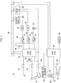
- FIG. 1 is a block diagram illustrating a configuration of a vehicle start control apparatus according to an embodiment of the present invention.
- a vehicle start control apparatus 10 is an apparatus used in an AT (Automatic Transmission) vehicle, wherein a so-called one push start system (hereinafter, referred to as the "OSS") and a so-called Keyless Operation System (hereinafter, referred to as the "KOS”) are employed. More specifically, the vehicle start control apparatus 10 starts an engine in response to a depression of a push start switch 14 while a brake pedal 12 is being depressed by a driver, by means of the OSS. The vehicle start control apparatus 10 also unlocks a steering lock mechanism 18 to permit operations of the steering by means of the KOS, once a portable electronic key (hereinafter, referred to as the "FOB key”) 16 is authenticated.
- OSS push start system
- KOS Keyless Operation System
- the vehicle start control apparatus 10 includes an OSS ECU (electronic control unit, control unit) 20 that controls start of the engine, powering on and off of accessories (hereinafter, referred to as "ACC") 32, an ignition plug (hereinafter, referred to as the "IG plug") 36 of the vehicle, and the like, and the push start switch 14, a stop lamp switch 22, a brake switch 24, the steering lock mechanism 18, an ACC relay 26, an IG relay 28, and a starter relay 30, which are connected to OSS ECU 20.
- the vehicle start control apparatus 10 also includes a KOS ECU 40 that authenticates the FOB key 16 and controls the steering lock mechanism 18, and an FOB box 42, an antenna 44, and a buzzer 46, which are connected to the KOS ECU 40. It is noted that the steering lock mechanism 18 is also connected to the KOS ECU 40.
- the vehicle start control apparatus 10 also includes an engine ECU 50 and an electric parts ECU 52 connected to the OSS ECU 20 via a CAN (control area network) 48.
- the push start switch 14 is a push-type switch disposed on an instrument panel in front of the driver's seat, and is turned on in response to a depression of a pressed portion by the driver.
- the push start switch 14 includes a warning light integrated therein. This warning light is lit on or off under the control of the OSS ECU 20.
- the FOB key 16 is a portable transmitter which is attached to or detached from the FOB box 42.
- ID information is communicated between the FOB key 16 and the KOS ECU 40.
- the ID information is communicated between the FOB key 16 and the KOS ECU 40 through wireless communications between the FOB key 16 and the antenna 44.
- the steering lock mechanism 18 is a mechanism to prohibit the steering from being operated by locking the steering, or permits the operation by unlocking the steering.
- the steering lock mechanism 18 is controlled by the KOS ECU 40, depending on a result of matching of the ID information in the FOB key 16.
- the stop lamp switch 22 is a switch which is turned ON while the brake pedal 12 is being depressed, or is turned OFF while the brake pedal 12 is not depressed. In response to the stop lamp switch 22 turning ON, a battery 34 and a stop lamp 54 are electrically connected each other and the stop lamp 54 is turned on.
- the stop lamp switch 22 is a switch which is turned OFF (a first state) while the brake pedal 12 is being depressed, or is turned ON (a second state) while the brake pedal 12 is not depressed.
- the engine ECU 50 performs a so-called cruise control to maintain a vehicle speed to a preset value while the brake switch 24 is ON.
- the ACC relay 26 is disposed in a circuit connecting the battery 34 to the ACC 32, and electrically connects or disconnects between the battery 34 and the ACC 32 under the control of the OSS ECU 20. It is noted that the ACC 32 includes audio devices, lighting, such as the room lamp, and the air conditioning apparatus of the vehicle.
- the IG relay 28 is disposed in a circuit connecting the battery 34 to the IG plug 36, and electrically connects or disconnects between the battery 34 and the IG plug 36 under the control of the OSS ECU 20.
- the starter relay 30 is disposed in a circuit connecting the battery 34 to the starter motor 38, and electrically connects or disconnects between the battery 34 and the starter motor 38 under the control of the OSS ECU 20.
- the FOB box 42 is disposed on the instrument panel in front of the driver's seat, and includes a switch that is turned on in response to the FOB key 16 being inserted to the FOB box 42. Once that switch is turned on, the ID information is communicated between the FOB key 16 and the KOS ECU 40.
- the antenna 44 is disposed on the instrument panel in the cabin of the vehicle, for example, and wirelessly communicates the ID information with the FOB key 16.
- the buzzer 46 is an audio producing device for issuing a warning sound outside the cabin, and is controlled by the KOS ECU 40, depending on a result of matching of the ID information in the FOB key 16.
- the KOS ECU 40 unlocks the steering lock mechanism 18 if ID information that has been stored in advance matches ID information received from the FOB key 16, and when the push start switch 14 is turned on while the stop lamp switch 22 is ON.
- the KOS ECU 40 instructs the buzzer 46 to issue the warning sound if the ID information that has been stored in advance does not matches the ID information received from the FOB key 16, and when the stop lamp switch 22 and the push start switch 14 are turned on.
- FIG. 2 is a block diagram illustrating the configuration of the OSS of the vehicle start control apparatus 10.
- the stop lamp switch 22 and the brake switch 24 are switches turned on or off in conjunction with operation of the brake pedal 12.
- the stop lamp switch 22 and the brake switch 24 are toggle switches turned on or off in conjunction with each other. More specifically, the brake switch 24 is turned off when the stop lamp switch 22 is ON, whereas the brake switch 24 is turned on when the stop lamp switch 22 is OFF.
- the stop lamp switch 22 when the brake pedal 12 is depressed, the stop lamp switch 22 is turned on and the brake switch 24 is turned off. In this case, the stop lamp 54 is lit on and the cruise control by the engine ECU 50 is disabled. In contrast, when the brake pedal 12 is not depressed, the stop lamp switch 22 is turned off and the brake switch 24 is turned on. In this case, the stop lamp 54 is lit off and the cruise control by the engine ECU 50 is enabled.
- the OSS ECU 20 stores a control program for performing a start control on the vehicle, depending on whether the stop lamp switch 22 and the brake switch 24 are ON or OFF.
- the start control of the vehicle is performed by the OSS ECU 20 in accordance with the control program.
- the KOS ECU 40 performs matching on the ID information in the FOB key 16, and the OSS ECU 20 initiates the start control of the vehicle if the prestored ID information matches the received ID information.
- the OSS ECU 20 stores how ON/OFF of the two switches 22 and 24 has been changed after the vehicle start control was initiated, as a history.
- the OSS ECU 20 permits start of the engine if the push start switch 14 is ON when the stop lamp switch 22 is ON and the brake switch 24 is OFF, thereby starting the engine.
- the OSS ECU 20 sets NG flags for the two switches 22 and 24 to ON if the stop lamp switch 22 is ON and the brake switch 24 is not OFF (if a negative determination is made in a first determination which will be described later) .
- the OSS ECU 20 then executes the warning processing.
- the OSS ECU 20 does not permit start of the engine in this case.
- the OSS ECU 20 sets the NG flag only for the stop lamp switch 22 to OFF.
- the brake switch 24 changes from OFF to ON, and then to OFF, in this order, the OSS ECU 20 sets the NG flag only for the brake switch 24 to OFF.
- the OSS ECU 20 terminates the warning processing, and permits start of the engine if the push start switch 14 is ON.
- the OSS ECU 20 continues execution of the warning processing, instead of terminating it, and permits start of the engine if the push start switch 14 is ON.
- the vehicle start control is performed based on the determination whether the stop lamp switch 22 and the brake switch 24 are ON or OFF as described above, the vehicle start control may be performed based on determination whether a clutch interlock switch 122 and clutch monitoring switch 124, which will be described later in the third embodiment, are ON or OFF, in place of using the switches 22 and 24.
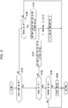
- controls as shown in FIGS. 3 and 4 are performed by the OSS ECU (control unit) 20. These control flows are performed periodically, for example, at every dozens of milliseconds.
- Step A100 the OSS ECU 20 determines whether or not the stop lamp switch 22 is ON. If a positive determination is made in this step, the flow transitions to Step A102. Otherwise, if a negative determination is made, the flow transitions to Step A104.
- Step A102 the OSS ECU 20 determines whether or not the brake switch 24 is OFF. If a positive determination is made in this step, the flow transitions to Step A106. Otherwise, if a negative determination is made, the flow transitions to Step A103 wherein the NG flags for the two switches 22 and 24 are set to ON. After performing a warning in Step A110, the flow transitions to a second determination.
- Step A104 the OSS ECU 20 determines whether or not the brake switch 24 is OFF. If a positive determination is made in this step, the flow transitions to Step A105. Otherwise, if a negative determination is made, the current processing routine is terminated.
- Step A105 after the NG flags for the two switches 22 and 24 are set to ON. After performing the warning in Step A110, the flow transitions to the second determination.
- Steps A100-102 the OSS ECU 20 determines whether or not the stop lamp switch 22 is ON and the brake switch 24 is OFF.
- Step A100-102 the OSS ECU 20 determines whether the stop lamp switch 22 and the brake switch 24 are turned on or off in response to a depression of the brake pedal 12, that is, whether the stop lamp switch 22 and the brake switch 24 are both functioning properly. If a positive determination is made in the determination in Steps A100-102 (first determination), the flow transitions to Step A106. Otherwise, if a negative determination is made, the flow transitions to Step A103 or Step A104.
- Step A106 the OSS ECU 20 determines whether or not the push start switch 14 is ON. If a positive determination is made, the flow transitions to Step A108. Otherwise, if a negative determination is made, the current processing routine is terminated.
- Step A108 the OSS ECU 20 electrically connects the ACC 32, the IG plug 36, and the starter motor 38 to the battery 34 by energizing the ACC relay 26, the IG relay 28, and the starter relay 30 to operate the ACC 32, the IG plug 36, and the starter motor 38. Once the IG plug 36 and the starter motor 38 are operated, the engine is started. With that the processing routine is completed at this step.
- the OSS ECU 20 permits start of the engine.
- the NG flags for the two switches 22 and 24 are set to ON for storing a failure state of any of the switches 22 and 24 in Step A103. After performing the processing in Step A110, the flow transition to the second determination.
- Step A104 the OSS ECU 20 determines whether or not the brake switch 24 is OFF. If a negative determination is made in this step, the current processing routine is terminated. Otherwise, if a positive determination is made in this step, the flow transitions to Step A105.
- Step A105 the NG flags for the two switches 22 and 24 are set to ON, for storing a failure state of any of the switches 22 and 24.
- the OSS ECU 20 performs the warning processing (WARNING) to turn on the warning light integrated in the push start switch 14, and transitions to the second determination.
- the NG flags for the two switches are set to ON in Steps A103 and A104 for the following reason. If the brake switch 24 is ON and a negative determination is made in Step A102 while the brake pedal 12 is not depressed, for example, the brake switch 24 is turned ON properly (without being fixed) while the stop lamp switch 22 is fixed to ON (failed), since the brake pedal 12 is not depressed. On the other hand, if a negative determination is made in Step A102 while the brake pedal 12 is being depressed, the stop lamp switch 22 is turned ON properly (without being fixed) while the brake switch 24 is fixed to ON, since the brake pedal 12 is depressed.
- the NG flags for the two switches 22 and 24 are set to ON, since which of the switch 22 or the switch 24 fails cannot be determined.
- the NG flags for the two switches 22 and 24 are set to ON in the Step A105, since which of the switch 22 or the switch 24 fails cannot be determined.
- Step A200 the OSS ECU 20 determines whether the stop lamp switch 22 changes from ON to OFF, and then to ON, in this order, for checking whether the user has depressed the brake pedal 12 again. If a positive determination is made, the flow transitions to Step A202. Otherwise, if a negative determination is made, the flow transitions to Step A204. Since the output from the stop lamp switch 22 changes from ON to OFF, and then to ON in response to the user depressing the brake pedal 12 again, it can be confirmed that the stop lamp switch 22 is not fixed to OFF or fixed to ON. Incidentially that determination in this Step A200 can be made by the OSS ECU 20, by referring to the stored history of the change of the stop lamp switch 22, from ON to OFF, and from OFF to ON, for example.
- Step A202 only the NG flag for the stop lamp switch 22 is set to OFF. The flow then transitions to Step A204.
- Step A204 it is determined whether the brake switch 24 changes from OFF to ON, and then to OFF. If a positive determination is made, the flow transitions to Step A206. Otherwise, if a negative determination is made, the flow transitions to Step A208. Since the output from the brake switch 24 changes from OFF to ON, then to OFF in response to the user depressing the brake pedal 12 again, it can be confirmed that the brake switch 24 is not fixed to OFF or fixed to ON. Similarly, that determination in this Step A200 can be made by the OSS ECU 20, by referring to the stored history indicating how ON/OFF of the brake switch 24 changes.
- Step A206 only the NG flag for the brake switch 24 is set to OFF. The flow then transitions to Step A208.
- Step A208 it is determined whether the NG flag for the stop lamp switch 22 and the NG flag for the brake switch 24 are both OFF. If a positive determination is made in Step A208, the flow transitions to Step A212. If a negative determination is made, the flow transitions to Step A210. If a positive determination is made in Step A200 and a positive determination is made in Step A204, a positive determination is made in Step A208. If a negative determination is made at least one of Steps A200 and A204, a negative determination is made in Step A208.
- Step A210 it is determined whether the NG flag for the stop lamp switch 22 and the NG flag for the brake switch 24 are both ON. If a positive determination is made, the flow transitions to the first determination and the current processing routine is terminated. If a negative determination is made, the flow transitions to Step A214. If a negative determination is made in Step A200 and a negative determination is made in Step A204, a positive determination is made in Step A210. If a positive determination is made in at least one of Steps A200 and A204, a negative determination is made in Step A210.
- Step A212 the warning processing is terminated, and the flow transitions to Step A214.
- Step A214 it is determined whether or not the push start switch 14 has been ON for a predetermined period of time. If a positive determination is made, an engine start is permitted in Step A216 and this processing routine is terminated. If a negative determination is made, the flow transitions to the first determination and the current processing routine is terminated.
- Steps A200-Step A202 and the determination of the change in ON/OFF state of the brake switch 24 in Step A204-Step A206 may be performed first. After the determination of the change in the state of the brake switch 24, the change in the state of the stop lamp switch 22 may be determined.
- the vehicle start control apparatus 10 can prevent the engine from being started, bypassing execution of the warning processing, when the brake pedal 12 is not depressed. Further, if either the stop lamp switch 22 or the brake switch 24 fails, the warning processing is performed and start of the engine can be permitted when the user depresses the brake pedal 12 once again and the push start switch 14 is operated.
- Step A200 a negative determination is made in Step A200 and a positive determination is made in Step A204, that is, if the OSS ECU 20 determines that the stop lamp switch 22 fails while the brake switch 24 is operating correctly in response to the second depression of the brake pedal 12.
- Step A200 a positive determination is made in Step A200 and a negative determination is made in Step A204, that is, if the OSS ECU 20 determines that the brake switch 24 fails while the stop lamp switch 22 is operating correctly in response to the second depression of the brake pedal 12.
- a failure of the stop lamp switch 22 or the brake switch 24 can be detected based on two depressions of the brake pedal 12, i.e., an operation routinely made by the driver, rather than special operations, such as a depression of the push start switch 14 for longer than a predetermined period of time (so-called "press and hold"). Accordingly, the drive's operation can be simplified for starting the engine when either of the switches 22 and 24 fails.
- start of the engine can be permitted by determining that the other switch 22 or 24 functions properly (does not fail).
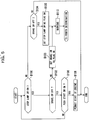
- FIGS. 5 and 6 are flowcharts illustrating a vehicle start control according to a second embodiment. With reference to FIGS. 5 and 6 , together with FIGS. 1 and 2 , a second embodiment of a vehicle start control apparatus of the present invention will be described.
- the present embodiment is different in terms of the configuration of the OSS ECU 20, i.e., the configuration of the software provided as a control program of the computer, but other configurations are same as those in the first embodiment. Only the differences will be described herein.
- the stop lamp switch 22 is rarely fixed to ON (failure), but frequently fixed to OFF (failure) .
- the brake switch 24 is rarely fixed to OFF (failure), but frequently fixed to ON (failure). Further, disconnection may occur in the switches 22 and 24. For example, if the cable for the brake switch 24 is broken, the brake switch 24 becomes always OFF and depression of the brake pedal 12 is detected even if it is not depressed.
- the present embodiment is aimed at preventing a false start of the engine due to such a cause.
- the OSS ECU 20 stores a control program for performing a start control on the vehicle, depending ON or OFF of the stop lamp switch 22 and the brake switch 24.
- the start control of the vehicle is performed by the OSS ECU 20 in accordance with the control program.
- the KOS ECU 40 performs matching on the ID information in the FOB key 16, and the OSS ECU 20 initiates the start control of the vehicle if the prestored ID information matches the received ID information.
- the OSS ECU 20 stores how ON/OFF of the two switches 22 and 24 has been changed after the vehicle start control was initiated as a history.
- the OSS ECU 20 permits start of the engine if the push start switch 14 is ON when the stop lamp switch 22 is ON and the brake switch 24 is OFF, to start the engine.
- the OSS ECU 20 sets the NG flag for the stop lamp switch 22 to ON. Then the OSS ECU 20 performs the warning processing and transitions to a fourth determination which will be described later.
- the OSS ECU 20 sets the NG flag for the brake switch 24 to ON. Then the OSS ECU 20 performs the warning processing and transitions to a fourth determination which will be described later.
- the OSS ECU 20 sets all of the NG flags for the two switches 22 and 24 to OFF if the stop lamp switch 22 is ON and the brake switch 24 is OFF, when the stop lamp switch 22 changes from ON to OFF or the brake switch 24 changes from OFF to ON, after execution of the warning processing described above.
- the OSS ECU 20 terminates the warning processing and permits start of the engine, if the push start switch 14 has been ON for a predetermined period of time.
- the OSS ECU 20 permits start of the engine if the brake switch 24 is OFF, even if the stop lamp switch 22 is OFF, when the stop lamp switch 22 changes from ON to OFF or the brake switch 24 changes from OFF to ON after execution of the warning processing described above.
- the OSS ECU 20 stores a control program for performing a start control on the vehicle, depending ON or OFF of the stop lamp switch 22 and the brake switch 24.
- a method of controlling a start of a vehicle performed by the OSS ECU 20 in accordance with the control program will be described with reference to the flowcharts in FIGS. 5 and 6 .
- the KOS ECU 40 performs matching on the ID information in the FOB key 16, and this processing routine is initiated and is transitioned to step B100 if the prestored ID information matches the received ID information.
- the OSS ECU 20 determines whether or not the stop lamp switch 22 is ON. If a positive determination is made in this step, the flow transitions to Step B102. Otherwise, if a negative determination is made, the flow transitions to Step B104.
- Step B102 the OSS ECU 20 determines whether or not the brake switch 24 is OFF. If a positive determination is made in this step, the flow transitions to Step B106. Otherwise, if a negative determination is made, the flow transitions to Step B103 wherein the brake switch NG flags is set to ON. After performing a warning in Step B110, the flow transitions to a fourth determination.
- Step B104 the OSS ECU 20 determines whether or not the brake switch 24 is OFF. If a positive determination is made in this step, the flow transitions to Step B105. Otherwise, if a negative determination is made, the processing routine is terminated.
- Steps B100-102 the OSS ECU 20 determines whether or not the stop lamp switch 22 is ON and the brake switch 24 is OFF.
- Step B100-102 the OSS ECU 20 determines whether the stop lamp switch 22 and the brake switch 24 are turned ON or OFF in conjunction with depression of the brake pedal 12 within a predetermined period of time after this processing routine was initiated, that is, whether both the stop lamp switch 22 and the brake switch 24 are functioning properly. If a positive determination is made in the determination in Steps B100-102 (third determination), the flow transitions to Step B106. Otherwise, if a negative determination is made, the flow transitions to Step B103.
- Step B106 the OSS ECU 20 determines whether or not the push start switch 14 is ON. If a positive determination is made, the flow transitions to Step B108. Otherwise, if a negative determination is made, the flow returns to step B100.
- Step B108 the OSS ECU 20 electrically connects the ACC 32, the IG plug 36, and the starter motor 38 to the battery 34 by energizing the ACC relay 26, the IG relay 28, and the starter relay 30 to operate the ACC 32, the IG plug 36, and the starter motor 38. Once the IG plug 36 and the starter motor 38 are operated, the engine is started. With that the processing routine is completed at this step.
- the OSS ECU 20 permits start of the engine.
- Step B110 the brake switch NG flag is turned on in Step B103 for storing a failure state of the brake switch 24.
- Step B104 the OSS ECU 20 determines whether or not the brake switch 24 is OFF. If a negative determination is made in this step, the processing is terminated. Otherwise, if a positive determination is made in this step, the flow transitions to Step B105.
- Step B105 the stop lamp switch NG flag is set to ON for storing the failure state of the stop lamp switch 22.
- the OSS ECU 20 performs a warning processing to turn on the warning light integrated in the push start switch 14, and transitions to the fourth determination.
- stop lamp switch 22 fails if the stop lamp switch 22 is OFF and the brake switch 24 is OFF, and the stop lamp failure flag is set to ON and the flow transitions to the fourth determination. Otherwise, it is considered that the brake switch 24 fails if the stop lamp switch 22 is ON and the brake switch 24 is ON, and the flow transitions to the fourth determination.
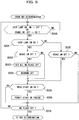
- Step B200 the OSS ECU 20 determines whether the stop lamp switch 22 changes from ON to OFF, or the brake switch 24 changes from OFF to ON, for checking whether the user has depressed the brake pedal 12 again. If a positive determination is made, the flow transitions to Step B201. Otherwise, if a negative determination is made, the processing routine is terminated. Since the outputs from the switches change from ON to OFF, and then to ON, or change from OFF to ON, then to OFF, in response to the user depressing the brakes pedal 12 again, it can be confirmed that at least one of the switches is not fixed to OFF or fixed to ON.
- Step B201 the OSS ECU 20 determines whether or not the stop lamp is ON. If a positive determination is made, the flow transitions to Step B202. Otherwise, if a negative determination is made, the flow transitions to a fifth determination in Step B205.
- Step B202 the OSS ECU 20 determines whether or not the brake switch 24 is OFF. If a positive determination is made, the flow transitions to Step B203. Otherwise, if a negative determination is made, the flow transitions to Step B206.
- Step B203 all NG flags are set to OFF by assuming that the failure state is recovered, and the flow transitions to Step B204.
- Step B204 the warning processing is terminated, and the flow transitions to Step B206.
- Step B205 the OSS ECU 20 determines whether or not the brake switch 24 is OFF. If a positive determination is made, the flow transitions to Step B206. Otherwise, if a negative determination is made, the flow transitions to Step B209.
- Step B206 the OSS ECU 20 determines whether or not the push start switch 14 has been OFF for a predetermined period of time. If a positive determination is made, start of the engine is permitted in Step B208 and then the flow transitions to Step B209. Otherwise, if a negative determination is made, the flow transitions to Step B209.
- Step B209 the OSS ECU 20 determines whether or not the all of the NG flags are OFF. If a positive determination is made, the flow transitions to a third determination. Otherwise, if a negative determination is made, the processing starting from Step B200 is repeated.
- the OSS ECU 20 stores the failure state of the stop lamp switch 22 and permits start of the engine.
- the brake switch 24 correctly changes from ON to OFF in response to a depression of the brake pedal 12
- the stop lamp switch 22 experiences the so-called OFF failure (fixed to OFF) wherein the stop lamp switch 22 never changes from the OFF state.
- the OSS ECU 20 performs the warning processing and permits start of the engine.
- the OSS ECU 20 stores the failure state of the brake switch 24 and permits start of the engine.
- the brake switch 24 experiences the so-called ON failure (fixed to ON) wherein the brake switch 24 never changes from the ON state.
- the OSS ECU 20 permits start of the engine after the determinations of Steps B201-205.
- the brake switch 24 experiences the so-called ON failure (fixed to ON) wherein the brake switch 24 never changes from the ON state.
- the OSS ECU 20 performs the warning processing and permits start of the engine.
- the vehicle start control apparatus 10 can prevent the engine from being started, bypassing execution of the warning processing, when the brake pedal 12 is not depressed. Further, if either the stop lamp switch 22 or the brake switch 24 fails, the warning processing is performed and start of the engine can be permitted when the user depresses the brake pedal 12 once again and the push start switch is operated.
- the vehicle start control apparatus 10 if the OSS ECU 20 determines that the stop lamp switch 22 is OFF and the brake switch 24 is OFF in the determinations in Steps B201 and 205, that is, the brake switch 24 correctly switches in response to the second depression of the brake pedal 12 but the stop lamp switch 22 is OFF failed, the flow transitions to Step B206. Accordingly, the vehicle start control apparatus 10 according to this embodiment can prevent start of the engine from being continuously blocked due to an OFF failure of the stop lamp switch 22 even when the brake pedal 12 is being depressed.
- the vehicle start control apparatus 10 if the OSS ECU 20 determines that the stop lamp switch 22 is ON and the brake switch 24 is ON in the fourth determination in Steps B201 and 202, that is, the stop lamp switch 22 correctly switches in response to the second depression of the brake pedal 12 but the brake switch 24 is ON failed, the flow transitions to Step B206. Accordingly, the vehicle start control apparatus 10 according to this embodiment can prevent start of the engine from being continuously blocked due to an ON failure of the brake switch 24 even when the brake pedal 12 is being depressed.
- an ON failure and an OFF failure of the stop lamp switch 22 can be detected based on two depressions of the brake pedal 12, i.e., an operation routinely made by the driver, rather than special operations, such as a depression of the push start switch 14 for longer than a predetermined period of time (so-called "press and hold"). Accordingly, the drive's operation can be simplified for starting the engine when the stop lamp switch 22 fails. Further, since the engine is started in response to two depressions of the brake pedal 12, which is a routine operation made by the driver, it is expected that blocking of start of the engine can be canceled even if the driver does not know the operation to start the engine upon the failure of the stop lamp switch 22.
- FIGS. 7 to 9 illustrate a vehicle start apparatus as a third embodiment of the present invention.
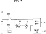
- FIG. 7 is a block diagram illustrating the configuration of the OSS of a vehicle start control apparatus 100 according to the third embodiment
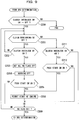
- FIGS. 8 and 9 are flowcharts illustrating a method for controlling a start of a vehicle.
- the vehicle start control apparatus 100 is an apparatus used in a MT (Manual Transmission) vehicle, wherein an OSS and a KOS are employed. More specifically, the vehicle start control apparatus 100 starts an engine in response to a depression of a push start switch 14 while a clutch pedal is depressed by a driver.
- MT Manual Transmission
- the vehicle start control apparatus 100 includes a clutch interlock switch 122 (first switch) and a clutch monitoring switch 124 (second switch).
- the clutch interlock switch 122 is a switch which is turned ON while the clutch pedal is being depressed, or is turned OFF while the clutch pedal is not depressed.
- the starter relay 30 is turned ON and the battery 34 and the starter motor 38 are electrically connected each other.
- the clutch monitoring switch 124 is a switch provided in the cruise control system, and is turned OFF (a first state) while the clutch pedal is being depressed, or is turned ON (a second state) while the clutch pedal is not depressed.
- the engine ECU 50 performs a cruise control while the clutch monitoring switch 124 is ON.
- the clutch interlock switch 122 and the clutch monitoring switch 124 are switches turned ON or OFF in conjunction with operation of the clutch pedal.
- the clutch interlock switch 122 and the clutch monitoring switch 124 are toggle switches turned ON or OFF in conjunction with each other. More specifically, the clutch monitoring switch 124 is turned off when the clutch interlock switch 122 is ON, whereas the clutch monitoring switch 124 is turned ON when the clutch interlock switch 122 is OFF.
- the OSS ECU 20 stores a control program for performing a start control on the vehicle, depending whether the clutch interlock switch 122 and the clutch monitoring switch 124 are ON or OFF.
- the start control of the vehicle performed by the OSS ECU 20 in accordance with the control program will be described with reference to the flowcharts in FIGS. 8 and 9 .
- the KOS ECU 40 performs matching on the ID information in the FOB key 16, and a processing routine of the start control of the vehicle is initiated by the OSS ECU 20 and is transitioned to step C100 if the prestored ID information matches the received ID information.
- Step C100 the OSS ECU 20 determines whether or not the clutch monitoring switch 124 is ON. If a positive determination is made in the determination of this step, the flow transitions to Step C102. Otherwise, if a negative determination is made in the determination of this step, the flow transitions to Step C104.
- Step C102 the OSS ECU 20 determines whether or not the clutch monitoring switch 124 is ON. If a positive determination is made in the determination of this step, the flow transitions to Step C106. Otherwise, if a negative determination is made, the flow transitions to Step C103.
- Step C106 the OSS ECU 20 determines whether or not the push start switch 14 is ON. If a positive determination is made in the determination of this step, the flow transitions to Step C108 to permit start of the engine. Otherwise, if a negative determination is made, start of the engine is not permitted and the flow returns to Step C100.
- Step C103 the OSS ECU 20 determines whether or not the push start switch 14 is ON. If a positive determination is made in the determination of this step, the warning processing in Step C110 is performed. After the flow transitions to Step C115 to set the NG flag to ON, the processing is terminated. Otherwise, if a negative determination is made, the flow returns to Step C100.
- Step C104 the OSS ECU 20 determines whether or not the clutch interlock switch 122 is ON. If a positive determination is made in the determination of this step, the warning processing in Step C120 is performed. After the flow transitions to Step C125 to set the NG flag to ON, the flow transitions to the fourth determination.
- the OSS ECU 20 determines whether or not the clutch interlock switch 122 changes from OFF to ON. If a positive determination is made in the determination of this step, the flow transitions to Step C201. Otherwise, if a negative determination is made, the processing is terminated.
- Step C201 the OSS ECU 20 determines whether or not the clutch monitoring switch 124 is ON. If a positive determination is made in the determination of this step, the flow transitions to Step C202. Otherwise, if a negative determination is made, the flow transitions to Step C211.
- Step C202 the OSS ECU 20 determines whether or not the interlock monitoring switch 122 is turned ON. If a positive determination is made in the determination of this step, all of the NG flags are set to OFF in Step C203. The warning is turned OFF and the flow transitions to Step C205. Otherwise, if a negative determination is made, Step C201 is performed again.
- Step C205 the OSS ECU 20 determines whether or not the push start switch 14 is ON. If a positive determination is made in the determination of this step, the flow transitions to Step C208 to permit start of the engine and then transitions to Step C209.
- Step C211 it is determined whether or not the clutch interlock switch 122 is ON. If a positive determination is made in the determination of this step, the flow transitions to Step C212. Otherwise, if a negative determination is made, the flow transitions to Step C209.
- Step C212 the OSS ECU 20 determines whether or not the push start switch 14 is ON. If a positive determination is made in the determination of this step, the flow transitions to Step C208 to permit start of the engine and then transitions to Step C209.
- the clutch interlock switch 122 changes from ON to OFF and the clutch interlock switch 122 is turned ON while the clutch monitoring switch 124 is ON and if the push start switch 14 is turned ON, within the above-described predetermined period of time after execution of the warning processing, it is determined that the clutch monitoring switch 124 fails and an permission to start the engine is issued.
- the vehicle start control apparatus 100 can prevent the engine from being started, bypassing execution of the warning processing, when the clutch 12 is not depressed.
- a switch which is turned OFF in response to a depression of a pedal such as the brake pedal 12 or the clutch pedal, and is turned ON in response to release of the depression of the pedal, as the second switch in the above-described embodiments, other switches which are turned ON in response to the depression or turned OFF in response to the depression, may also be used.
- the present invention is applicable to controls on any other machines than vehicles, which include a switch that is turned ON or OFF in response to an operation by an operator, and are started by monitoring the ON/OFF state of that switch.
Description
- The present invention relates to a vehicle start control apparatus.
- A so-called push start engine start system has been known, wherein a driver can start an engine by pressing a push start switch while depressing a brake pedal (refers to
Patent Reference 1, for example) . With such a system, even if depression of the brake pedal is not detected for some reasons, the driver can start the engine by pressing and holding the start switch. -
US 2007/087898 A1 discloses a passive start system with invalid brake ON-OFF switch state, in which the passive start system includes a brake system having a primary brake pedal switch associated with a brake pedal and the state of the primary brake pedal switch is monitored to achieve desired operation of the passive start system. The passive start system also includes a secondary brake pedal switch that is monitored to ensure that the state of the brake system is accurate, for example, if the primary brake pedal switch has malfunctioned, and the passive start system monitors the primary brake pedal switch and/or the secondary brake system switch and starts the vehicle in response to a passive start signal when the brakes of the brake system are engaged. - Patent Reference 1: Japanese Laid-open Patent Publication No.
2006-283727 - In a situation where depression of the brake pedal is continued to be detected for some reasons even if it is not actually depressed, a false start of the engine must be prevented. However, the system as described above does not handle such a situation.
- The present invention was conceived of in view of the above issue, and an object thereof is to provide a vehicle start control apparatus that can prevent the engine from being falsely started in a situation where depression of the brake pedal is continued to be detected for some reasons even if the brake pedal is not actually depressed.
- In order to achieve the above object, a vehicle start control apparatus according to the present invention is a vehicle start control apparatus that starts an engine when an engine start switch is operated while a pedal is being depressed, the vehicle start control apparatus including: a first switch that is turned ON in response to a depression of the pedal, and is turned OFF in response to the depression of the pedal being released; a second switch that assumes a first state being one of ON and OFF in response to the depression of the pedal, and assumes a second state being the other of ON and OFF in response to the depression of the pedal being released; and a control unit that performs a first determination to determine whether or not the first switch is ON and the second switch is in the first state; starts the engine if a positive determination is made in the first determination and if the engine start switch is operated; and performs a second determination determining whether or not the pedal is depressed twice by determining whether or not the first switch or the second switch changes from ON to OFF, and then to ON, or from OFF to ON, and then to OFF after a negative determination is made in the first determination, and determines whether or not one of the first switch and the second switch used for the determination of whether the pedal is depressed twice indicates the depression of the pedal, and starts the engine, if a positive determination is made in the second determination and if the engine start switch is operated.
- A second vehicle start control apparatus of the present invention is a vehicle start control apparatus that starts an engine when an engine start switch is operated while a pedal is being depressed, the vehicle start control apparatus including: a first switch that is turned ON in response to a depression of the pedal, and is turned OFF in response to the depression of the pedal being released; a second switch that assumes a first state being one of ON and OFF in response to the depression of the pedal, and assumes a second state being the other of ON and OFF in response to the depression of the pedal being released; and a control unit that performs a third determination to determine whether or not the first switch is ON and the second switch is in the first state; starts the engine, if a positive determination is made in the third determination and if the engine start switch is operated; and performs a fourth determination determining whether or not the pedal is depressed again by determining whether or not the first switch or the second switch changes from ON to OFF, or from OFF to ON after a negative determination is made in the third determination, and determines whether or not the first switch is ON and the second switch is in the second state, and starts the engine, if a positive determination is made in the fourth determination and if the engine start switch is operated.
- In the above-described vehicle start control apparatus, the control unit, after determining whether or not the pedal is depressed twice by determining whether or not the first switch or the second switch changes from ON to OFF, and then to ON, or from OFF to ON, and then to OFF after the negative determination is made in the third determination, perform a fifth determination to determine whether or not the first switch is OFF and the second switch is in the first state, and start the engine if a positive determination is made in the fifth determination and if the engine start switch is operated.
- In the above-described vehicle start control apparatuses, the first switch may be a stop lamp switch to turn on or off a stop lamp, and the second switch may be a brake switch to disable a cruise control function in the first state.
- In the above-described vehicle start control apparatuses, the first switch may be a clutch interlock switch to electrically connect or disconnect between a starter motor and a power source, and the second switch may be a clutch monitoring switch to disable a cruise control function in the first state.
- The vehicle start control apparatus according to the present invention can prevent the engine from being falsely started in a situation where depression of the brake pedal is continued to be detected for some reasons even if the brake pedal is not actually depressed.
-
-
FIG. 1 is a block diagram illustrating the configuration of a vehicle start control apparatus according to a first embodiment of the present invention; -
FIG. 2 is a block diagram illustrating the configuration of an OSS of the vehicle start control apparatus according to the first embodiment of the present invention; -
FIG. 3 is a flowchart illustrating a method of controlling a start of a vehicle according to the first embodiment of the present invention; -
FIG. 4 is a flowchart illustrating a method of controlling a start of a vehicle according to the first embodiment of the present invention; -
FIG. 5 is a flowchart illustrating a method of controlling a start of a vehicle according to a second embodiment of the present invention; -
FIG. 6 is a flowchart illustrating a method of controlling a start of a vehicle according to the second embodiment of the present invention; -
FIG. 7 is a block diagram illustrating the configuration of an OSS of a vehicle start control apparatus according to a third embodiment of the present invention; -
FIG. 8 is a flowchart illustrating a method of controlling a start of a vehicle according to the third embodiment of the present invention; and -
FIG. 9 is a flowchart illustrating the method of controlling a start of a vehicle according to the third embodiment of the present invention. -
- 10
- VEHICLE START CONTROL APPARATUS
- 12
- BRAKE PEDAL
- 14
- PUSH START SWITCH
- 16
- FOB KEY
- 18
- STEERING LOCK MECHANISM
- 20
- OSS ECU (CONTROL UNIT)
- 22
- STOP LAMP SWITCH (FIRST SWITCH)
- 24
- BRAKE SWITCH (SECOND SWITCH)
- 26
- ACC RELAY
- 28
- IG RELAY
- 30
- STARTER RELAY
- 32
- ACC
- 34
- BATTERY
- 36
- IG PLUG
- 38
- STARTER MOTOR
- 40
- KOS ECU
- 42
- FOB BOX
- 44
- ANTENNA
- 46
- BUZZER
- 48
- CAN
- 50
- ENGINE ECU
- 52
- ELECTRIC PARTS ECU
- 54
- STOP LAMP
- 100
- VEHICLE START CONTROL APPARATUS
- 122
- CLUTCH INTERLOCK SWITCH (FIRST SWITCH)
- 124
- CLUTCH MONITORING SWITCH (SECOND SWITCH)
- Hereinafter, embodiments of the present invention will be described with reference to the drawings.
-
FIGS. 1 to 4 illustrate a vehicle start control apparatus as a first embodiment of the present invention, which will be described with reference to the drawings. -
FIG. 1 is a block diagram illustrating a configuration of a vehicle start control apparatus according to an embodiment of the present invention. As shown inFIG. 1 , a vehiclestart control apparatus 10 according to this embodiment is an apparatus used in an AT (Automatic Transmission) vehicle, wherein a so-called one push start system (hereinafter, referred to as the "OSS") and a so-called Keyless Operation System (hereinafter, referred to as the "KOS") are employed. More specifically, the vehiclestart control apparatus 10 starts an engine in response to a depression of apush start switch 14 while abrake pedal 12 is being depressed by a driver, by means of the OSS. The vehicle startcontrol apparatus 10 also unlocks asteering lock mechanism 18 to permit operations of the steering by means of the KOS, once a portable electronic key (hereinafter, referred to as the "FOB key") 16 is authenticated. - The vehicle start
control apparatus 10 includes an OSS ECU (electronic control unit, control unit) 20 that controls start of the engine, powering on and off of accessories (hereinafter, referred to as "ACC") 32, an ignition plug (hereinafter, referred to as the "IG plug") 36 of the vehicle, and the like, and the push startswitch 14, astop lamp switch 22, abrake switch 24, thesteering lock mechanism 18, anACC relay 26, anIG relay 28, and astarter relay 30, which are connected toOSS ECU 20. The vehicle startcontrol apparatus 10 also includes aKOS ECU 40 that authenticates theFOB key 16 and controls thesteering lock mechanism 18, and anFOB box 42, anantenna 44, and abuzzer 46, which are connected to theKOS ECU 40. It is noted that thesteering lock mechanism 18 is also connected to theKOS ECU 40. The vehicle startcontrol apparatus 10 also includes anengine ECU 50 and anelectric parts ECU 52 connected to theOSS ECU 20 via a CAN (control area network) 48. - The push start
switch 14 is a push-type switch disposed on an instrument panel in front of the driver's seat, and is turned on in response to a depression of a pressed portion by the driver. The push startswitch 14 includes a warning light integrated therein. This warning light is lit on or off under the control of theOSS ECU 20. - The
FOB key 16 is a portable transmitter which is attached to or detached from theFOB box 42. When theFOB key 16 is attached to theFOB box 42, ID information is communicated between theFOB key 16 and theKOS ECU 40. When theFOB key 16 is not attached to theFOB box 42, the ID information is communicated between theFOB key 16 and theKOS ECU 40 through wireless communications between theFOB key 16 and theantenna 44. - The
steering lock mechanism 18 is a mechanism to prohibit the steering from being operated by locking the steering, or permits the operation by unlocking the steering. Thesteering lock mechanism 18 is controlled by theKOS ECU 40, depending on a result of matching of the ID information in theFOB key 16. - The
stop lamp switch 22 is a switch which is turned ON while thebrake pedal 12 is being depressed, or is turned OFF while thebrake pedal 12 is not depressed. In response to thestop lamp switch 22 turning ON, abattery 34 and astop lamp 54 are electrically connected each other and thestop lamp 54 is turned on. - The
stop lamp switch 22 is a switch which is turned OFF (a first state) while thebrake pedal 12 is being depressed, or is turned ON (a second state) while thebrake pedal 12 is not depressed. Theengine ECU 50 performs a so-called cruise control to maintain a vehicle speed to a preset value while thebrake switch 24 is ON. - The
ACC relay 26 is disposed in a circuit connecting thebattery 34 to theACC 32, and electrically connects or disconnects between thebattery 34 and theACC 32 under the control of theOSS ECU 20. It is noted that theACC 32 includes audio devices, lighting, such as the room lamp, and the air conditioning apparatus of the vehicle. - The
IG relay 28 is disposed in a circuit connecting thebattery 34 to theIG plug 36, and electrically connects or disconnects between thebattery 34 and theIG plug 36 under the control of theOSS ECU 20. Thestarter relay 30 is disposed in a circuit connecting thebattery 34 to thestarter motor 38, and electrically connects or disconnects between thebattery 34 and thestarter motor 38 under the control of theOSS ECU 20. - The
FOB box 42 is disposed on the instrument panel in front of the driver's seat, and includes a switch that is turned on in response to the FOB key 16 being inserted to theFOB box 42. Once that switch is turned on, the ID information is communicated between theFOB key 16 and theKOS ECU 40. Theantenna 44 is disposed on the instrument panel in the cabin of the vehicle, for example, and wirelessly communicates the ID information with theFOB key 16. Thebuzzer 46 is an audio producing device for issuing a warning sound outside the cabin, and is controlled by theKOS ECU 40, depending on a result of matching of the ID information in theFOB key 16. - The
KOS ECU 40 unlocks thesteering lock mechanism 18 if ID information that has been stored in advance matches ID information received from theFOB key 16, and when the push startswitch 14 is turned on while thestop lamp switch 22 is ON. TheKOS ECU 40 instructs thebuzzer 46 to issue the warning sound if the ID information that has been stored in advance does not matches the ID information received from theFOB key 16, and when thestop lamp switch 22 and the push startswitch 14 are turned on. -
FIG. 2 is a block diagram illustrating the configuration of the OSS of the vehiclestart control apparatus 10. As shown in this diagram, thestop lamp switch 22 and thebrake switch 24 are switches turned on or off in conjunction with operation of thebrake pedal 12. Thestop lamp switch 22 and thebrake switch 24 are toggle switches turned on or off in conjunction with each other. More specifically, thebrake switch 24 is turned off when thestop lamp switch 22 is ON, whereas thebrake switch 24 is turned on when thestop lamp switch 22 is OFF. - Thus, when the
brake pedal 12 is depressed, thestop lamp switch 22 is turned on and thebrake switch 24 is turned off. In this case, thestop lamp 54 is lit on and the cruise control by theengine ECU 50 is disabled. In contrast, when thebrake pedal 12 is not depressed, thestop lamp switch 22 is turned off and thebrake switch 24 is turned on. In this case, thestop lamp 54 is lit off and the cruise control by theengine ECU 50 is enabled. - The
OSS ECU 20 stores a control program for performing a start control on the vehicle, depending on whether thestop lamp switch 22 and thebrake switch 24 are ON or OFF. The start control of the vehicle is performed by theOSS ECU 20 in accordance with the control program. - The
KOS ECU 40 performs matching on the ID information in theFOB key 16, and theOSS ECU 20 initiates the start control of the vehicle if the prestored ID information matches the received ID information. - It is noted that the
OSS ECU 20 stores how ON/OFF of the twoswitches - The
OSS ECU 20 permits start of the engine if the push startswitch 14 is ON when thestop lamp switch 22 is ON and thebrake switch 24 is OFF, thereby starting the engine. - In contrast, the
OSS ECU 20 sets NG flags for the twoswitches stop lamp switch 22 is ON and thebrake switch 24 is not OFF (if a negative determination is made in a first determination which will be described later) . TheOSS ECU 20 then executes the warning processing. TheOSS ECU 20 does not permit start of the engine in this case. - After execution of the warning processing described above, when the
stop lamp switch 22 changes from ON to OFF, and then to ON, in this order, theOSS ECU 20 sets the NG flag only for thestop lamp switch 22 to OFF. When thebrake switch 24 changes from OFF to ON, and then to OFF, in this order, theOSS ECU 20 sets the NG flag only for thebrake switch 24 to OFF. - If the NG flags of the
switches OSS ECU 20 terminates the warning processing, and permits start of the engine if the push startswitch 14 is ON. - On the other hand, if one of the NG flags of the
switches OSS ECU 20 continues execution of the warning processing, instead of terminating it, and permits start of the engine if the push startswitch 14 is ON. - Further, in the present embodiment, the vehicle start control is performed based on the determination whether the
stop lamp switch 22 and thebrake switch 24 are ON or OFF as described above, the vehicle start control may be performed based on determination whether aclutch interlock switch 122 andclutch monitoring switch 124, which will be described later in the third embodiment, are ON or OFF, in place of using theswitches - Since the start control apparatus for a vehicle according to the first embodiment of the present invention is configured as described above, controls as shown in
FIGS. 3 and4 , for example, are performed by the OSS ECU (control unit) 20. These control flows are performed periodically, for example, at every dozens of milliseconds. - This processing routine is initiated if the
KOS ECU 40 performs matching on the ID information in theFOB key 16 and the prestored ID information matches the received ID information, and if the engine has not been started. Further, once the engine is started, this processing routine is terminated. This processing routine is also performed only for a certain period of time after the routine is initiated. First, the flow transitions to Step A100. In Step A100, theOSS ECU 20 determines whether or not thestop lamp switch 22 is ON. If a positive determination is made in this step, the flow transitions to Step A102. Otherwise, if a negative determination is made, the flow transitions to Step A104. - In Step A102, the
OSS ECU 20 determines whether or not thebrake switch 24 is OFF. If a positive determination is made in this step, the flow transitions to Step A106. Otherwise, if a negative determination is made, the flow transitions to Step A103 wherein the NG flags for the twoswitches - On the other hand, in Step A104, the
OSS ECU 20 determines whether or not thebrake switch 24 is OFF. If a positive determination is made in this step, the flow transitions to Step A105. Otherwise, if a negative determination is made, the current processing routine is terminated. - In Step A105, after the NG flags for the two
switches - In other words, in Steps A100-102, the
OSS ECU 20 determines whether or not thestop lamp switch 22 is ON and thebrake switch 24 is OFF. Here, in Step A100-102, theOSS ECU 20 determines whether thestop lamp switch 22 and thebrake switch 24 are turned on or off in response to a depression of thebrake pedal 12, that is, whether thestop lamp switch 22 and thebrake switch 24 are both functioning properly. If a positive determination is made in the determination in Steps A100-102 (first determination), the flow transitions to Step A106. Otherwise, if a negative determination is made, the flow transitions to Step A103 or Step A104. - In Step A106, the
OSS ECU 20 determines whether or not the push startswitch 14 is ON. If a positive determination is made, the flow transitions to Step A108. Otherwise, if a negative determination is made, the current processing routine is terminated. In Step A108, theOSS ECU 20 electrically connects theACC 32, theIG plug 36, and thestarter motor 38 to thebattery 34 by energizing theACC relay 26, theIG relay 28, and thestarter relay 30 to operate theACC 32, theIG plug 36, and thestarter motor 38. Once theIG plug 36 and thestarter motor 38 are operated, the engine is started. With that the processing routine is completed at this step. - More specifically, if the
stop lamp switch 22 properly changes from OFF to ON in response depression of thebrake pedal 12, and thebrake switch 24 properly changes from ON to OFF in conjunction with thestop lamp switch 22, theOSS ECU 20 permits start of the engine. - In contrast, the NG flags for the two
switches switches - Further, in Step A104, the
OSS ECU 20 determines whether or not thebrake switch 24 is OFF. If a negative determination is made in this step, the current processing routine is terminated. Otherwise, if a positive determination is made in this step, the flow transitions to Step A105. - In Step A105, the NG flags for the two
switches switches OSS ECU 20 performs the warning processing (WARNING) to turn on the warning light integrated in the push startswitch 14, and transitions to the second determination. - In other words, it is considered that either of the
switches stop lamp switch 22 is OFF and thebrake switch 24 is OFF. The failure flags (NG flags) for the twoswitches switches stop lamp switch 22 is ON and thebrake switch 24 is ON. The failure flags (NG flags) for the twoswitches - The NG flags for the two switches are set to ON in Steps A103 and A104 for the following reason. If the
brake switch 24 is ON and a negative determination is made in Step A102 while thebrake pedal 12 is not depressed, for example, thebrake switch 24 is turned ON properly (without being fixed) while thestop lamp switch 22 is fixed to ON (failed), since thebrake pedal 12 is not depressed. On the other hand, if a negative determination is made in Step A102 while thebrake pedal 12 is being depressed, thestop lamp switch 22 is turned ON properly (without being fixed) while thebrake switch 24 is fixed to ON, since thebrake pedal 12 is depressed. Thus, if one of these negative determinations is made, the NG flags for the twoswitches switch 22 or theswitch 24 fails cannot be determined. Similarly, if it is determined that thestop lamp switch 22 is OFF in Step A100, the NG flags for the twoswitches switch 22 or theswitch 24 fails cannot be determined. - As shown in the flowchart in
FIG. 4 , in the second determination, in Step A200, theOSS ECU 20 determines whether thestop lamp switch 22 changes from ON to OFF, and then to ON, in this order, for checking whether the user has depressed thebrake pedal 12 again. If a positive determination is made, the flow transitions to Step A202. Otherwise, if a negative determination is made, the flow transitions to Step A204. Since the output from thestop lamp switch 22 changes from ON to OFF, and then to ON in response to the user depressing thebrake pedal 12 again, it can be confirmed that thestop lamp switch 22 is not fixed to OFF or fixed to ON. Incidentially that determination in this Step A200 can be made by theOSS ECU 20, by referring to the stored history of the change of thestop lamp switch 22, from ON to OFF, and from OFF to ON, for example. - In Step A202, only the NG flag for the
stop lamp switch 22 is set to OFF. The flow then transitions to Step A204. - In Step A204, it is determined whether the
brake switch 24 changes from OFF to ON, and then to OFF. If a positive determination is made, the flow transitions to Step A206. Otherwise, if a negative determination is made, the flow transitions to Step A208. Since the output from thebrake switch 24 changes from OFF to ON, then to OFF in response to the user depressing thebrake pedal 12 again, it can be confirmed that thebrake switch 24 is not fixed to OFF or fixed to ON. Similarly, that determination in this Step A200 can be made by theOSS ECU 20, by referring to the stored history indicating how ON/OFF of thebrake switch 24 changes. - In Step A206, only the NG flag for the
brake switch 24 is set to OFF. The flow then transitions to Step A208. - In Step A208, it is determined whether the NG flag for the
stop lamp switch 22 and the NG flag for thebrake switch 24 are both OFF. If a positive determination is made in Step A208, the flow transitions to Step A212. If a negative determination is made, the flow transitions to Step A210. If a positive determination is made in Step A200 and a positive determination is made in Step A204, a positive determination is made in Step A208. If a negative determination is made at least one of Steps A200 and A204, a negative determination is made in Step A208. - In Step A210, it is determined whether the NG flag for the
stop lamp switch 22 and the NG flag for thebrake switch 24 are both ON. If a positive determination is made, the flow transitions to the first determination and the current processing routine is terminated. If a negative determination is made, the flow transitions to Step A214. If a negative determination is made in Step A200 and a negative determination is made in Step A204, a positive determination is made in Step A210. If a positive determination is made in at least one of Steps A200 and A204, a negative determination is made in Step A210. - In Step A212, the warning processing is terminated, and the flow transitions to Step A214.
- In Step A214, it is determined whether or not the push start
switch 14 has been ON for a predetermined period of time. If a positive determination is made, an engine start is permitted in Step A216 and this processing routine is terminated. If a negative determination is made, the flow transitions to the first determination and the current processing routine is terminated. - Either of the determination of the change in ON/OFF state of the
stop lamp switch 22 in Steps A200-Step A202 and the determination of the change in ON/OFF state of thebrake switch 24 in Step A204-Step A206 may be performed first. After the determination of the change in the state of thebrake switch 24, the change in the state of thestop lamp switch 22 may be determined. - Accordingly, the vehicle
start control apparatus 10 according to this embodiment can prevent the engine from being started, bypassing execution of the warning processing, when thebrake pedal 12 is not depressed. Further, if either thestop lamp switch 22 or thebrake switch 24 fails, the warning processing is performed and start of the engine can be permitted when the user depresses thebrake pedal 12 once again and the push startswitch 14 is operated. - Further, it is possible to prevent start of the engine from being continuously blocked even when the
brake pedal 12 is depressed due to a failure of thestop lamp switch 22, if a negative determination is made in Step A200 and a positive determination is made in Step A204, that is, if theOSS ECU 20 determines that thestop lamp switch 22 fails while thebrake switch 24 is operating correctly in response to the second depression of thebrake pedal 12. - Further, it is possible to prevent start of the engine from being continuously blocked even when the
brake pedal 12 is depressed due to a failure of thestop lamp switch 22, if a positive determination is made in Step A200 and a negative determination is made in Step A204, that is, if theOSS ECU 20 determines that thebrake switch 24 fails while thestop lamp switch 22 is operating correctly in response to the second depression of thebrake pedal 12. - Further, a failure of the
stop lamp switch 22 or thebrake switch 24 can be detected based on two depressions of thebrake pedal 12, i.e., an operation routinely made by the driver, rather than special operations, such as a depression of the push startswitch 14 for longer than a predetermined period of time (so-called "press and hold"). Accordingly, the drive's operation can be simplified for starting the engine when either of theswitches - In addition, even when either of the
switches switches brake pedal 12 is depressed, start of the engine can be permitted by determining that theother switch -
FIGS. 5 and6 are flowcharts illustrating a vehicle start control according to a second embodiment. With reference toFIGS. 5 and6 , together withFIGS. 1 and2 , a second embodiment of a vehicle start control apparatus of the present invention will be described. - The present embodiment is different in terms of the configuration of the
OSS ECU 20, i.e., the configuration of the software provided as a control program of the computer, but other configurations are same as those in the first embodiment. Only the differences will be described herein. - It is noted that the present embodiment was made in view of most frequent failure of the
stop lamp switch 22 and thebrake switch 24. - More specifically, for example, while the vehicle is parked, the
brake pedal 12 is not depressed and generally thestop lamp switch 22 has been OFF and thebrake switch 24 has been ON for a longer period of time. Accordingly, thestop lamp switch 22 is rarely fixed to ON (failure), but frequently fixed to OFF (failure) . - Similarly, the
brake switch 24 is rarely fixed to OFF (failure), but frequently fixed to ON (failure). Further, disconnection may occur in theswitches brake switch 24 is broken, thebrake switch 24 becomes always OFF and depression of thebrake pedal 12 is detected even if it is not depressed. - Accordingly, if the
stop lamp switch 22 is fixed to ON or the cable for thebrake switch 24 is disconnected, depression of thebrake pedal 12 is detected even if it is not depressed, which results in a false start of the engine. - The present embodiment is aimed at preventing a false start of the engine due to such a cause.
- The
OSS ECU 20 stores a control program for performing a start control on the vehicle, depending ON or OFF of thestop lamp switch 22 and thebrake switch 24. The start control of the vehicle is performed by theOSS ECU 20 in accordance with the control program. - The
KOS ECU 40 performs matching on the ID information in theFOB key 16, and theOSS ECU 20 initiates the start control of the vehicle if the prestored ID information matches the received ID information. - It is noted that the
OSS ECU 20 stores how ON/OFF of the twoswitches - The
OSS ECU 20 permits start of the engine if the push startswitch 14 is ON when thestop lamp switch 22 is ON and thebrake switch 24 is OFF, to start the engine. - In contrast, if the
stop lamp switch 22 is OFF and thebrake switch 24 is OFF, theOSS ECU 20 sets the NG flag for thestop lamp switch 22 to ON. Then theOSS ECU 20 performs the warning processing and transitions to a fourth determination which will be described later. - Besides, if the
stop lamp switch 22 is ON and thebrake switch 24 is ON, theOSS ECU 20 sets the NG flag for thebrake switch 24 to ON. Then theOSS ECU 20 performs the warning processing and transitions to a fourth determination which will be described later. - The
OSS ECU 20 sets all of the NG flags for the twoswitches stop lamp switch 22 is ON and thebrake switch 24 is OFF, when thestop lamp switch 22 changes from ON to OFF or thebrake switch 24 changes from OFF to ON, after execution of the warning processing described above. TheOSS ECU 20 terminates the warning processing and permits start of the engine, if the push startswitch 14 has been ON for a predetermined period of time. - In contrast, the
OSS ECU 20 permits start of the engine if thebrake switch 24 is OFF, even if thestop lamp switch 22 is OFF, when thestop lamp switch 22 changes from ON to OFF or thebrake switch 24 changes from OFF to ON after execution of the warning processing described above. - Here, the
OSS ECU 20 stores a control program for performing a start control on the vehicle, depending ON or OFF of thestop lamp switch 22 and thebrake switch 24. Hereinafter, a method of controlling a start of a vehicle performed by theOSS ECU 20 in accordance with the control program will be described with reference to the flowcharts inFIGS. 5 and6 . - The
KOS ECU 40 performs matching on the ID information in theFOB key 16, and this processing routine is initiated and is transitioned to step B100 if the prestored ID information matches the received ID information. In Step B100, theOSS ECU 20 determines whether or not thestop lamp switch 22 is ON. If a positive determination is made in this step, the flow transitions to Step B102. Otherwise, if a negative determination is made, the flow transitions to Step B104. - In Step B102, the
OSS ECU 20 determines whether or not thebrake switch 24 is OFF. If a positive determination is made in this step, the flow transitions to Step B106. Otherwise, if a negative determination is made, the flow transitions to Step B103 wherein the brake switch NG flags is set to ON. After performing a warning in Step B110, the flow transitions to a fourth determination. - On the other hand, in Step B104, the
OSS ECU 20 determines whether or not thebrake switch 24 is OFF. If a positive determination is made in this step, the flow transitions to Step B105. Otherwise, if a negative determination is made, the processing routine is terminated. - In other words, in Steps B100-102, the
OSS ECU 20 determines whether or not thestop lamp switch 22 is ON and thebrake switch 24 is OFF. Here, in Step B100-102, theOSS ECU 20 determines whether thestop lamp switch 22 and thebrake switch 24 are turned ON or OFF in conjunction with depression of thebrake pedal 12 within a predetermined period of time after this processing routine was initiated, that is, whether both thestop lamp switch 22 and thebrake switch 24 are functioning properly. If a positive determination is made in the determination in Steps B100-102 (third determination), the flow transitions to Step B106. Otherwise, if a negative determination is made, the flow transitions to Step B103. - In Step B106, the
OSS ECU 20 determines whether or not the push startswitch 14 is ON. If a positive determination is made, the flow transitions to Step B108. Otherwise, if a negative determination is made, the flow returns to step B100. In Step B108, theOSS ECU 20 electrically connects theACC 32, theIG plug 36, and thestarter motor 38 to thebattery 34 by energizing theACC relay 26, theIG relay 28, and thestarter relay 30 to operate theACC 32, theIG plug 36, and thestarter motor 38. Once theIG plug 36 and thestarter motor 38 are operated, the engine is started. With that the processing routine is completed at this step. - More specifically, if the
stop lamp switch 22 properly changes from OFF to ON in response depression of thebrake pedal 12, and thebrake switch 24 properly changes from ON to OFF in conjunction with thestop lamp switch 22, theOSS ECU 20 permits start of the engine. - In contrast, the brake switch NG flag is turned on in Step B103 for storing a failure state of the
brake switch 24. After performing the processing in Step B110, the flow transitions to the fourth determination. Next, in Step B104, theOSS ECU 20 determines whether or not thebrake switch 24 is OFF. If a negative determination is made in this step, the processing is terminated. Otherwise, if a positive determination is made in this step, the flow transitions to Step B105. - In Step B105, the stop lamp switch NG flag is set to ON for storing the failure state of the
stop lamp switch 22. Thereafter, in Step B110, theOSS ECU 20 performs a warning processing to turn on the warning light integrated in the push startswitch 14, and transitions to the fourth determination. - More specifically, it is considered that the
stop lamp switch 22 fails if thestop lamp switch 22 is OFF and thebrake switch 24 is OFF, and the stop lamp failure flag is set to ON and the flow transitions to the fourth determination. Otherwise, it is considered that thebrake switch 24 fails if thestop lamp switch 22 is ON and thebrake switch 24 is ON, and the flow transitions to the fourth determination. - As shown in the flowchart in
FIG. 6 , in the fourth determination, in Step B200, theOSS ECU 20 determines whether thestop lamp switch 22 changes from ON to OFF, or thebrake switch 24 changes from OFF to ON, for checking whether the user has depressed thebrake pedal 12 again. If a positive determination is made, the flow transitions to Step B201. Otherwise, if a negative determination is made, the processing routine is terminated. Since the outputs from the switches change from ON to OFF, and then to ON, or change from OFF to ON, then to OFF, in response to the user depressing thebrakes pedal 12 again, it can be confirmed that at least one of the switches is not fixed to OFF or fixed to ON. - In Step B201, the
OSS ECU 20 determines whether or not the stop lamp is ON. If a positive determination is made, the flow transitions to Step B202. Otherwise, if a negative determination is made, the flow transitions to a fifth determination in Step B205. - In Step B202, the
OSS ECU 20 determines whether or not thebrake switch 24 is OFF. If a positive determination is made, the flow transitions to Step B203. Otherwise, if a negative determination is made, the flow transitions to Step B206. - In Step B203, all NG flags are set to OFF by assuming that the failure state is recovered, and the flow transitions to Step B204.
- In Step B204, the warning processing is terminated, and the flow transitions to Step B206.
- On the other hand, in a fifth determination on Step B205, the
OSS ECU 20 determines whether or not thebrake switch 24 is OFF. If a positive determination is made, the flow transitions to Step B206. Otherwise, if a negative determination is made, the flow transitions to Step B209. - In Step B206, the
OSS ECU 20 determines whether or not the push startswitch 14 has been OFF for a predetermined period of time. If a positive determination is made, start of the engine is permitted in Step B208 and then the flow transitions to Step B209. Otherwise, if a negative determination is made, the flow transitions to Step B209. - In Step B209, the
OSS ECU 20 determines whether or not the all of the NG flags are OFF. If a positive determination is made, the flow transitions to a third determination. Otherwise, if a negative determination is made, the processing starting from Step B200 is repeated. - In other words, when the push start
switch 14 is operated in the situation where thestop lamp switch 22 is turned OFF and thebrake switch 24 is turned OFF in response to thebrake pedal 12 being depressed again after the execution of the warning processing, theOSS ECU 20 stores the failure state of thestop lamp switch 22 and permits start of the engine. In such a situation, while thebrake switch 24 correctly changes from ON to OFF in response to a depression of thebrake pedal 12, thestop lamp switch 22 experiences the so-called OFF failure (fixed to OFF) wherein thestop lamp switch 22 never changes from the OFF state. Thus, theOSS ECU 20 performs the warning processing and permits start of the engine. - On the other hand, when the push start
switch 14 is operated in the situation where thestop lamp switch 22 is turned ON and thebrake switch 24 is turned ON in response to thebrake pedal 12 being depressed again within the above-described predetermined period of time after the execution of the warning processing, theOSS ECU 20 stores the failure state of thebrake switch 24 and permits start of the engine. In such a situation, while thestop lamp switch 22 correctly changes from OFF to ON in response to a depression of thebrake pedal 12, thebrake switch 24 experiences the so-called ON failure (fixed to ON) wherein thebrake switch 24 never changes from the ON state. Thus, theOSS ECU 20 permits start of the engine after the determinations of Steps B201-205. In such a situation, while thestop lamp switch 22 correctly changes from OFF to ON in response to a depression of thebrake pedal 12, thebrake switch 24 experiences the so-called ON failure (fixed to ON) wherein thebrake switch 24 never changes from the ON state. Thus, theOSS ECU 20 performs the warning processing and permits start of the engine. - Accordingly, the vehicle
start control apparatus 10 according to this embodiment can prevent the engine from being started, bypassing execution of the warning processing, when thebrake pedal 12 is not depressed. Further, if either thestop lamp switch 22 or thebrake switch 24 fails, the warning processing is performed and start of the engine can be permitted when the user depresses thebrake pedal 12 once again and the push start switch is operated. - Further, in the vehicle
start control apparatus 10 according to this embodiment, if theOSS ECU 20 determines that thestop lamp switch 22 is OFF and thebrake switch 24 is OFF in the determinations in Steps B201 and 205, that is, thebrake switch 24 correctly switches in response to the second depression of thebrake pedal 12 but thestop lamp switch 22 is OFF failed, the flow transitions to Step B206. Accordingly, the vehiclestart control apparatus 10 according to this embodiment can prevent start of the engine from being continuously blocked due to an OFF failure of thestop lamp switch 22 even when thebrake pedal 12 is being depressed. - Further, in the vehicle
start control apparatus 10 according to this embodiment, if theOSS ECU 20 determines that thestop lamp switch 22 is ON and thebrake switch 24 is ON in the fourth determination in Steps B201 and 202, that is, thestop lamp switch 22 correctly switches in response to the second depression of thebrake pedal 12 but thebrake switch 24 is ON failed, the flow transitions to Step B206. Accordingly, the vehiclestart control apparatus 10 according to this embodiment can prevent start of the engine from being continuously blocked due to an ON failure of thebrake switch 24 even when thebrake pedal 12 is being depressed. - Further, in the vehicle
start control apparatus 10 according to this embodiment, an ON failure and an OFF failure of thestop lamp switch 22 can be detected based on two depressions of thebrake pedal 12, i.e., an operation routinely made by the driver, rather than special operations, such as a depression of the push startswitch 14 for longer than a predetermined period of time (so-called "press and hold"). Accordingly, the drive's operation can be simplified for starting the engine when thestop lamp switch 22 fails. Further, since the engine is started in response to two depressions of thebrake pedal 12, which is a routine operation made by the driver, it is expected that blocking of start of the engine can be canceled even if the driver does not know the operation to start the engine upon the failure of thestop lamp switch 22. -
FIGS. 7 to 9 illustrate a vehicle start apparatus as a third embodiment of the present invention.FIG. 7 is a block diagram illustrating the configuration of the OSS of a vehiclestart control apparatus 100 according to the third embodiment, andFIGS. 8 and9 are flowcharts illustrating a method for controlling a start of a vehicle. - The vehicle start
control apparatus 100 is an apparatus used in a MT (Manual Transmission) vehicle, wherein an OSS and a KOS are employed. More specifically, the vehiclestart control apparatus 100 starts an engine in response to a depression of apush start switch 14 while a clutch pedal is depressed by a driver. - The vehicle start
control apparatus 100 includes a clutch interlock switch 122 (first switch) and a clutch monitoring switch 124 (second switch). Theclutch interlock switch 122 is a switch which is turned ON while the clutch pedal is being depressed, or is turned OFF while the clutch pedal is not depressed. In response to theclutch interlock switch 122 being turned ON, thestarter relay 30 is turned ON and thebattery 34 and thestarter motor 38 are electrically connected each other. - The
clutch monitoring switch 124 is a switch provided in the cruise control system, and is turned OFF (a first state) while the clutch pedal is being depressed, or is turned ON (a second state) while the clutch pedal is not depressed. Theengine ECU 50 performs a cruise control while theclutch monitoring switch 124 is ON. - The
clutch interlock switch 122 and theclutch monitoring switch 124 are switches turned ON or OFF in conjunction with operation of the clutch pedal. Theclutch interlock switch 122 and theclutch monitoring switch 124 are toggle switches turned ON or OFF in conjunction with each other. More specifically, theclutch monitoring switch 124 is turned off when theclutch interlock switch 122 is ON, whereas theclutch monitoring switch 124 is turned ON when theclutch interlock switch 122 is OFF. - Here, the
OSS ECU 20 stores a control program for performing a start control on the vehicle, depending whether theclutch interlock switch 122 and theclutch monitoring switch 124 are ON or OFF. Hereinafter, the start control of the vehicle performed by theOSS ECU 20 in accordance with the control program will be described with reference to the flowcharts inFIGS. 8 and9 . - The
KOS ECU 40 performs matching on the ID information in theFOB key 16, and a processing routine of the start control of the vehicle is initiated by theOSS ECU 20 and is transitioned to step C100 if the prestored ID information matches the received ID information. - In Step C100, the
OSS ECU 20 determines whether or not theclutch monitoring switch 124 is ON. If a positive determination is made in the determination of this step, the flow transitions to Step C102. Otherwise, if a negative determination is made in the determination of this step, the flow transitions to Step C104. - In Step C102, the
OSS ECU 20 determines whether or not theclutch monitoring switch 124 is ON. If a positive determination is made in the determination of this step, the flow transitions to Step C106. Otherwise, if a negative determination is made, the flow transitions to Step C103. - In Step C106, the
OSS ECU 20 determines whether or not the push startswitch 14 is ON. If a positive determination is made in the determination of this step, the flow transitions to Step C108 to permit start of the engine. Otherwise, if a negative determination is made, start of the engine is not permitted and the flow returns to Step C100. - On the other hand, in Step C103, the
OSS ECU 20 determines whether or not the push startswitch 14 is ON. If a positive determination is made in the determination of this step, the warning processing in Step C110 is performed. After the flow transitions to Step C115 to set the NG flag to ON, the processing is terminated. Otherwise, if a negative determination is made, the flow returns to Step C100. - On the other hand, in Step C104, the
OSS ECU 20 determines whether or not theclutch interlock switch 122 is ON. If a positive determination is made in the determination of this step, the warning processing in Step C120 is performed. After the flow transitions to Step C125 to set the NG flag to ON, the flow transitions to the fourth determination. - As shown in the flowchart in
FIG. 9 , in the fourth determination, firstly in the Step C200, theOSS ECU 20 determines whether or not theclutch interlock switch 122 changes from OFF to ON. If a positive determination is made in the determination of this step, the flow transitions to Step C201. Otherwise, if a negative determination is made, the processing is terminated. - In Step C201, the
OSS ECU 20 determines whether or not theclutch monitoring switch 124 is ON. If a positive determination is made in the determination of this step, the flow transitions to Step C202. Otherwise, if a negative determination is made, the flow transitions to Step C211. - In Step C202, the
OSS ECU 20 determines whether or not theinterlock monitoring switch 122 is turned ON. If a positive determination is made in the determination of this step, all of the NG flags are set to OFF in Step C203. The warning is turned OFF and the flow transitions to Step C205. Otherwise, if a negative determination is made, Step C201 is performed again. - In Step C205, the
OSS ECU 20 determines whether or not the push startswitch 14 is ON. If a positive determination is made in the determination of this step, the flow transitions to Step C208 to permit start of the engine and then transitions to Step C209. - On the other hand, in Step C211, it is determined whether or not the
clutch interlock switch 122 is ON. If a positive determination is made in the determination of this step, the flow transitions to Step C212. Otherwise, if a negative determination is made, the flow transitions to Step C209. - In Step C212, the
OSS ECU 20 determines whether or not the push startswitch 14 is ON. If a positive determination is made in the determination of this step, the flow transitions to Step C208 to permit start of the engine and then transitions to Step C209. - In other words, the
clutch interlock switch 122 changes from ON to OFF and theclutch interlock switch 122 is turned ON while theclutch monitoring switch 124 is ON and if the push startswitch 14 is turned ON, within the above-described predetermined period of time after execution of the warning processing, it is determined that theclutch monitoring switch 124 fails and an permission to start the engine is issued. - Thereby, block of an engine start is prevented by a failure of the
clutch monitoring switch 124 alone. - Accordingly, the vehicle
start control apparatus 100 according to this embodiment can prevent the engine from being started, bypassing execution of the warning processing, when the clutch 12 is not depressed. - Although embodiments of the present invention have been described, the present invention is not limited to the embodiments described above and various modifications may be made without departing from the scope of the present invention as defined by the appended claims. For example, although the
brake switch 24 or theclutch monitoring switch 124 is used as the second switch in the above-described embodiments, other switches which are turned ON or OFF in response to the pedals, such as thebrake pedal 12 or the clutch pedal, may also be used. Further, although a switch which is turned OFF in response to a depression of a pedal, such as thebrake pedal 12 or the clutch pedal, and is turned ON in response to release of the depression of the pedal, as the second switch in the above-described embodiments, other switches which are turned ON in response to the depression or turned OFF in response to the depression, may also be used. - Note that those ordinary skilled in the art can practice the vehicle start apparatus of the present invention from the disclosure of embodiments of the present invention.
- The present invention is applicable to controls on any other machines than vehicles, which include a switch that is turned ON or OFF in response to an operation by an operator, and are started by monitoring the ON/OFF state of that switch.
Claims (5)
- A vehicle start control apparatus that starts an engine when an engine start switch (14) is operated while a pedal (12) is being depressed, the vehicle start control apparatus comprising:a first switch (22, 122) that is turned ON in response to a depression of the pedal (12), and is turned OFF in response to the depression of the pedal (12) being released;a second switch (24, 124) that assumes a first state being one of ON and OFF in response to the depression of the pedal (12), and assumes a second state being the other of ON and OFF in response to the depression of the pedal (12) being released; anda control unit (20) that performs a first determination to determine whether or not the first switch (22, 122) is ON and the second switch (24, 124) is in the first state; starts the engine if a positive determination is made in the first determination and if the engine start switch (14) is operated; and performs a second determination determining whether or not the pedal (12) is depressed twice by determining whether or not the first switch (22, 122) or the second switch (24, 124) changes from ON to OFF, and then to ON, or from OFF to ON, and then to OFF after a negative determination is made in the first determination, and determines whether or not one of the first switch (22, 122) and the second switch (24, 124) used for the determination of whether the pedal (12) is depressed twice indicates the depression of the pedal (12), and starts the engine, if a positive determination is made in the second determination and if the engine start switch (14) is operated.
- A vehicle start control apparatus that starts an engine when an engine start switch (14) is operated while a pedal (12) is being depressed, the vehicle start control apparatus comprising:a first switch (22, 122) that is turned ON in response to a depression of the pedal (12), and is turned OFF in response to the depression of the pedal (12) being released;a second switch (24, 124) that assumes a first state being one of ON and OFF in response to the depression of the pedal (12), and assumes a second state being the other of ON and OFF in response to the depression of the pedal (12) being released; anda control unit (20) that performs a third determination to determine whether or not the first switch (22, 122) is ON and the second switch (24, 124) is in the first state; starts the engine, if a positive determination is made in the third determination and if the engine start switch (14) is operated; and performs a fourth determination determining whether or not the pedal (12) is depressed again by determining whether or not the first switch (22, 122) or the second switch (24, 124) changes from ON to OFF or from OFF to ON after a negative determination is made in the third determination, and determines whether or not the first switch (22, 122) is ON and the second switch (24, 124) is in the second state, and starts the engine, if a positive determination is made in the fourth determination and if the engine start switch (14) is operated.
- The vehicle start control apparatus according to claim 2, wherein the control unit (20), after determining whether or not the pedal (12) is depressed twice by determining whether or not the first switch (22, 122) or the second switch (24, 124) changes from ON to OFF, and then to ON, or from OFF to ON, and then to OFF after the negative determination is made in the third determination, performs a fifth determination to determine whether or not the first switch (22, 122) is OFF and the second switch (24, 124) is in the first state, and starts the engine if a positive determination is made in the fifth determination and if the engine start switch (14) is operated.
- The vehicle start control apparatus according to claim 1 or 3, wherein the first switch (22) may be a stop lamp switch (22) to turn on or off a stop lamp, and the second switch (24) is a brake switch (24) to disable a cruise control function in the first state.
- The vehicle start control apparatus according to claim 1 or 3, wherein the first switch (122) is a clutch interlock switch (122) to electrically connect or disconnect between a starter motor and a power source, and the second switch (124) is a clutch monitoring switch (124) to disable a cruise control function in the first state.
Applications Claiming Priority (2)
| Application Number | Priority Date | Filing Date | Title |
|---|---|---|---|
| JP2009256915 | 2009-11-10 | ||
| PCT/JP2010/070024 WO2011059001A1 (en) | 2009-11-10 | 2010-11-10 | Vehicle starting control device |
Publications (3)
| Publication Number | Publication Date |
|---|---|
| EP2500554A1 EP2500554A1 (en) | 2012-09-19 |
| EP2500554A4 EP2500554A4 (en) | 2017-09-20 |
| EP2500554B1 true EP2500554B1 (en) | 2020-04-01 |
Family
ID=43991659
Family Applications (1)
| Application Number | Title | Priority Date | Filing Date |
|---|---|---|---|
| EP10829960.3A Active EP2500554B1 (en) | 2009-11-10 | 2010-11-10 | Vehicle starting control device |
Country Status (5)
| Country | Link |
|---|---|
| US (1) | US8855897B2 (en) |
| EP (1) | EP2500554B1 (en) |
| JP (1) | JP4957877B2 (en) |
| CN (1) | CN102695867B (en) |
| WO (1) | WO2011059001A1 (en) |
Families Citing this family (3)
| Publication number | Priority date | Publication date | Assignee | Title |
|---|---|---|---|---|
| JP6375969B2 (en) * | 2015-01-28 | 2018-08-22 | トヨタ自動車株式会社 | vehicle |
| FR3033540B1 (en) * | 2015-03-10 | 2017-03-24 | Peugeot Citroen Automobiles Sa | METHOD AND DEVICE FOR CHECKING THE OPENING / CLOSING OF THE TRANSMISSION CHAIN OF A VEHICLE FOLLOWING ANOTHER VEHICLE |
| US10480478B2 (en) | 2018-04-23 | 2019-11-19 | Fca Us Llc | Diagnostic techniques for a clutch interlock switch and a clutch pedal position sensor |
Family Cites Families (14)
| Publication number | Priority date | Publication date | Assignee | Title |
|---|---|---|---|---|
| US5742137A (en) * | 1994-07-05 | 1998-04-21 | Chrysler Corporation | Starter motor control circuit and method |
| KR100353985B1 (en) * | 1999-12-30 | 2002-09-27 | 현대자동차주식회사 | Sudden start preventing control system of a vehicle |
| JP4092503B2 (en) * | 2004-03-26 | 2008-05-28 | 日産自動車株式会社 | Engine starting device and engine starting method |
| JP4301194B2 (en) * | 2005-04-04 | 2009-07-22 | トヨタ自動車株式会社 | Vehicle start control device |
| JP4250149B2 (en) * | 2005-05-10 | 2009-04-08 | 株式会社デンソー | Engine start control system |
| GB2427440B (en) * | 2005-06-20 | 2008-01-30 | Ford Global Tech Llc | A method for stopping and starting an engine |
| US20070087898A1 (en) * | 2005-10-18 | 2007-04-19 | Siemens Vdo Automotive Corporation | Passive Start with invalid brake ON-OFF switch state |
| JP4121095B2 (en) * | 2006-04-19 | 2008-07-16 | 富士通テン株式会社 | Power management device, control system, and control method |
| JP4333690B2 (en) | 2006-05-12 | 2009-09-16 | 株式会社デンソー | Engine start control system |
| JP4438839B2 (en) | 2007-08-24 | 2010-03-24 | トヨタ自動車株式会社 | Control device for internal combustion engine |
| EP2222232B1 (en) | 2007-10-19 | 2018-12-12 | Ancora Heart, Inc. | Devices for locking and/or cutting tethers |
| JP5132454B2 (en) | 2008-07-14 | 2013-01-30 | ダイハツ工業株式会社 | Control device for idle stop car |
| JP2010059887A (en) * | 2008-09-04 | 2010-03-18 | Denso Corp | Engine control system |
| CN101380897A (en) * | 2008-10-21 | 2009-03-11 | 潘国峰 | Misoperation starting guard equipment in motor vehicle driving and method thereof |
-
2010
- 2010-11-10 CN CN201080049540.9A patent/CN102695867B/en not_active Expired - Fee Related
- 2010-11-10 EP EP10829960.3A patent/EP2500554B1/en active Active
- 2010-11-10 US US13/394,416 patent/US8855897B2/en not_active Expired - Fee Related
- 2010-11-10 JP JP2011540526A patent/JP4957877B2/en active Active
- 2010-11-10 WO PCT/JP2010/070024 patent/WO2011059001A1/en active Application Filing
Non-Patent Citations (1)
| Title |
|---|
| None * |
Also Published As
| Publication number | Publication date |
|---|---|
| CN102695867A (en) | 2012-09-26 |
| CN102695867B (en) | 2015-08-05 |
| JPWO2011059001A1 (en) | 2013-04-04 |
| US8855897B2 (en) | 2014-10-07 |
| JP4957877B2 (en) | 2012-06-20 |
| WO2011059001A1 (en) | 2011-05-19 |
| EP2500554A1 (en) | 2012-09-19 |
| US20120283937A1 (en) | 2012-11-08 |
| EP2500554A4 (en) | 2017-09-20 |
Similar Documents
| Publication | Publication Date | Title |
|---|---|---|
| US9764702B2 (en) | System and method for managing the electrical powering of at least one piece of equipment during the automatic restarting of an internal combustion engine of a vehicle | |
| JP4114666B2 (en) | Automatic stop control device for hybrid vehicle | |
| US7043354B2 (en) | Method for automatically starting an internal combustion engine | |
| US20110202201A1 (en) | Remote starting device and remote starting method | |
| US20100244560A1 (en) | Vehicle power supply system | |
| CN112277879A (en) | Vehicle starting control method and system | |
| JP5339877B2 (en) | SAFETY CONTROL DEVICE AND METHOD, AND PROGRAM | |
| EP2500554B1 (en) | Vehicle starting control device | |
| JP4464716B2 (en) | Drive system and automobile equipped with the same | |
| EP2474433B1 (en) | Electrically-driven vehicle | |
| JP2010077904A (en) | Control device for engine | |
| JP5278504B2 (en) | Steering lock drive circuit, steering lock device | |
| WO2021220340A1 (en) | Power supply control method and power supply control device | |
| US9296394B2 (en) | Engine non-stop warning apparatus | |
| KR20190047792A (en) | System for emergency stop in case of sudden automobile emergence and the method thereof | |
| JP5278908B2 (en) | Remote starter for vehicle and remote start system | |
| JP4539114B2 (en) | Drive system and automobile equipped with the same | |
| KR102390508B1 (en) | Apparatus for controlling electro mechanical brake system and method therof | |
| JP7310765B2 (en) | Vehicle control system and vehicle | |
| JP4961075B2 (en) | Programmable monitor system, especially automotive safety device with so-called hands-free monitor system | |
| KR101591776B1 (en) | Device For Controlling Automatical Lock of Automobile's Doors | |
| JPS63255152A (en) | Electric load controller for vehicle | |
| JP2005245083A (en) | Start controller for drive system and automobile mounting it | |
| KR20130066383A (en) | Method for operating of electronic control system | |
| CN115027273A (en) | Automobile emergency high voltage interruption control method and system and automobile |
Legal Events
| Date | Code | Title | Description |
|---|---|---|---|
| PUAI | Public reference made under article 153(3) epc to a published international application that has entered the european phase |
Free format text: ORIGINAL CODE: 0009012 |
|
| 17P | Request for examination filed |
Effective date: 20120326 |
|
| AK | Designated contracting states |
Kind code of ref document: A1 Designated state(s): AL AT BE BG CH CY CZ DE DK EE ES FI FR GB GR HR HU IE IS IT LI LT LU LV MC MK MT NL NO PL PT RO RS SE SI SK SM TR |
|
| DAX | Request for extension of the european patent (deleted) | ||
| RA4 | Supplementary search report drawn up and despatched (corrected) |
Effective date: 20170822 |
|
| RIC1 | Information provided on ipc code assigned before grant |
Ipc: F02D 29/02 20060101AFI20170816BHEP Ipc: F02N 11/08 20060101ALI20170816BHEP Ipc: F02N 11/10 20060101ALI20170816BHEP |
|
| STAA | Information on the status of an ep patent application or granted ep patent |
Free format text: STATUS: EXAMINATION IS IN PROGRESS |
|
| 17Q | First examination report despatched |
Effective date: 20190513 |
|
| RAP1 | Party data changed (applicant data changed or rights of an application transferred) |
Owner name: MITSUBISHI JIDOSHA ENGINEERING KABUSHIKI KAISHA Owner name: MITSUBISHI JIDOSHA KOGYO KABUSHIKI KAISHA |
|
| GRAP | Despatch of communication of intention to grant a patent |
Free format text: ORIGINAL CODE: EPIDOSNIGR1 |
|
| STAA | Information on the status of an ep patent application or granted ep patent |
Free format text: STATUS: GRANT OF PATENT IS INTENDED |
|
| INTG | Intention to grant announced |
Effective date: 20191014 |
|
| RIN1 | Information on inventor provided before grant (corrected) |
Inventor name: KAWAMOTO, TAKAYOSHI Inventor name: OHWAKI, TADAO Inventor name: NOMURA, YUSUKE Inventor name: HAZAMA, SUMIAKI Inventor name: UE, TAKASHI |
|
| GRAS | Grant fee paid |
Free format text: ORIGINAL CODE: EPIDOSNIGR3 |
|
| GRAA | (expected) grant |
Free format text: ORIGINAL CODE: 0009210 |
|
| STAA | Information on the status of an ep patent application or granted ep patent |
Free format text: STATUS: THE PATENT HAS BEEN GRANTED |
|
| AK | Designated contracting states |
Kind code of ref document: B1 Designated state(s): AL AT BE BG CH CY CZ DE DK EE ES FI FR GB GR HR HU IE IS IT LI LT LU LV MC MK MT NL NO PL PT RO RS SE SI SK SM TR |
|
| REG | Reference to a national code |
Ref country code: GB Ref legal event code: FG4D |
|
| REG | Reference to a national code |
Ref country code: CH Ref legal event code: EP Ref country code: AT Ref legal event code: REF Ref document number: 1251632 Country of ref document: AT Kind code of ref document: T Effective date: 20200415 |
|
| REG | Reference to a national code |
Ref country code: DE Ref legal event code: R096 Ref document number: 602010063761 Country of ref document: DE |
|
| REG | Reference to a national code |
Ref country code: IE Ref legal event code: FG4D |
|
| PG25 | Lapsed in a contracting state [announced via postgrant information from national office to epo] |
Ref country code: BG Free format text: LAPSE BECAUSE OF FAILURE TO SUBMIT A TRANSLATION OF THE DESCRIPTION OR TO PAY THE FEE WITHIN THE PRESCRIBED TIME-LIMIT Effective date: 20200701 |
|
| REG | Reference to a national code |
Ref country code: NL Ref legal event code: MP Effective date: 20200401 |
|
| REG | Reference to a national code |
Ref country code: LT Ref legal event code: MG4D |
|
| PG25 | Lapsed in a contracting state [announced via postgrant information from national office to epo] |
Ref country code: GR Free format text: LAPSE BECAUSE OF FAILURE TO SUBMIT A TRANSLATION OF THE DESCRIPTION OR TO PAY THE FEE WITHIN THE PRESCRIBED TIME-LIMIT Effective date: 20200702 Ref country code: FI Free format text: LAPSE BECAUSE OF FAILURE TO SUBMIT A TRANSLATION OF THE DESCRIPTION OR TO PAY THE FEE WITHIN THE PRESCRIBED TIME-LIMIT Effective date: 20200401 Ref country code: PT Free format text: LAPSE BECAUSE OF FAILURE TO SUBMIT A TRANSLATION OF THE DESCRIPTION OR TO PAY THE FEE WITHIN THE PRESCRIBED TIME-LIMIT Effective date: 20200817 Ref country code: NO Free format text: LAPSE BECAUSE OF FAILURE TO SUBMIT A TRANSLATION OF THE DESCRIPTION OR TO PAY THE FEE WITHIN THE PRESCRIBED TIME-LIMIT Effective date: 20200701 Ref country code: CZ Free format text: LAPSE BECAUSE OF FAILURE TO SUBMIT A TRANSLATION OF THE DESCRIPTION OR TO PAY THE FEE WITHIN THE PRESCRIBED TIME-LIMIT Effective date: 20200401 Ref country code: NL Free format text: LAPSE BECAUSE OF FAILURE TO SUBMIT A TRANSLATION OF THE DESCRIPTION OR TO PAY THE FEE WITHIN THE PRESCRIBED TIME-LIMIT Effective date: 20200401 Ref country code: LT Free format text: LAPSE BECAUSE OF FAILURE TO SUBMIT A TRANSLATION OF THE DESCRIPTION OR TO PAY THE FEE WITHIN THE PRESCRIBED TIME-LIMIT Effective date: 20200401 Ref country code: SE Free format text: LAPSE BECAUSE OF FAILURE TO SUBMIT A TRANSLATION OF THE DESCRIPTION OR TO PAY THE FEE WITHIN THE PRESCRIBED TIME-LIMIT Effective date: 20200401 Ref country code: IS Free format text: LAPSE BECAUSE OF FAILURE TO SUBMIT A TRANSLATION OF THE DESCRIPTION OR TO PAY THE FEE WITHIN THE PRESCRIBED TIME-LIMIT Effective date: 20200801 |
|
| REG | Reference to a national code |
Ref country code: AT Ref legal event code: MK05 Ref document number: 1251632 Country of ref document: AT Kind code of ref document: T Effective date: 20200401 |
|
| PG25 | Lapsed in a contracting state [announced via postgrant information from national office to epo] |
Ref country code: HR Free format text: LAPSE BECAUSE OF FAILURE TO SUBMIT A TRANSLATION OF THE DESCRIPTION OR TO PAY THE FEE WITHIN THE PRESCRIBED TIME-LIMIT Effective date: 20200401 Ref country code: LV Free format text: LAPSE BECAUSE OF FAILURE TO SUBMIT A TRANSLATION OF THE DESCRIPTION OR TO PAY THE FEE WITHIN THE PRESCRIBED TIME-LIMIT Effective date: 20200401 Ref country code: RS Free format text: LAPSE BECAUSE OF FAILURE TO SUBMIT A TRANSLATION OF THE DESCRIPTION OR TO PAY THE FEE WITHIN THE PRESCRIBED TIME-LIMIT Effective date: 20200401 |
|
| PG25 | Lapsed in a contracting state [announced via postgrant information from national office to epo] |
Ref country code: AL Free format text: LAPSE BECAUSE OF FAILURE TO SUBMIT A TRANSLATION OF THE DESCRIPTION OR TO PAY THE FEE WITHIN THE PRESCRIBED TIME-LIMIT Effective date: 20200401 |
|
| REG | Reference to a national code |
Ref country code: DE Ref legal event code: R097 Ref document number: 602010063761 Country of ref document: DE |
|
| PG25 | Lapsed in a contracting state [announced via postgrant information from national office to epo] |
Ref country code: ES Free format text: LAPSE BECAUSE OF FAILURE TO SUBMIT A TRANSLATION OF THE DESCRIPTION OR TO PAY THE FEE WITHIN THE PRESCRIBED TIME-LIMIT Effective date: 20200401 Ref country code: RO Free format text: LAPSE BECAUSE OF FAILURE TO SUBMIT A TRANSLATION OF THE DESCRIPTION OR TO PAY THE FEE WITHIN THE PRESCRIBED TIME-LIMIT Effective date: 20200401 Ref country code: DK Free format text: LAPSE BECAUSE OF FAILURE TO SUBMIT A TRANSLATION OF THE DESCRIPTION OR TO PAY THE FEE WITHIN THE PRESCRIBED TIME-LIMIT Effective date: 20200401 Ref country code: AT Free format text: LAPSE BECAUSE OF FAILURE TO SUBMIT A TRANSLATION OF THE DESCRIPTION OR TO PAY THE FEE WITHIN THE PRESCRIBED TIME-LIMIT Effective date: 20200401 Ref country code: EE Free format text: LAPSE BECAUSE OF FAILURE TO SUBMIT A TRANSLATION OF THE DESCRIPTION OR TO PAY THE FEE WITHIN THE PRESCRIBED TIME-LIMIT Effective date: 20200401 Ref country code: SM Free format text: LAPSE BECAUSE OF FAILURE TO SUBMIT A TRANSLATION OF THE DESCRIPTION OR TO PAY THE FEE WITHIN THE PRESCRIBED TIME-LIMIT Effective date: 20200401 Ref country code: IT Free format text: LAPSE BECAUSE OF FAILURE TO SUBMIT A TRANSLATION OF THE DESCRIPTION OR TO PAY THE FEE WITHIN THE PRESCRIBED TIME-LIMIT Effective date: 20200401 |
|
| PGFP | Annual fee paid to national office [announced via postgrant information from national office to epo] |
Ref country code: FR Payment date: 20201117 Year of fee payment: 11 Ref country code: DE Payment date: 20201127 Year of fee payment: 11 |
|
| PLBE | No opposition filed within time limit |
Free format text: ORIGINAL CODE: 0009261 |
|
| STAA | Information on the status of an ep patent application or granted ep patent |
Free format text: STATUS: NO OPPOSITION FILED WITHIN TIME LIMIT |
|
| PG25 | Lapsed in a contracting state [announced via postgrant information from national office to epo] |
Ref country code: PL Free format text: LAPSE BECAUSE OF FAILURE TO SUBMIT A TRANSLATION OF THE DESCRIPTION OR TO PAY THE FEE WITHIN THE PRESCRIBED TIME-LIMIT Effective date: 20200401 Ref country code: SK Free format text: LAPSE BECAUSE OF FAILURE TO SUBMIT A TRANSLATION OF THE DESCRIPTION OR TO PAY THE FEE WITHIN THE PRESCRIBED TIME-LIMIT Effective date: 20200401 |
|
| 26N | No opposition filed |
Effective date: 20210112 |
|
| PG25 | Lapsed in a contracting state [announced via postgrant information from national office to epo] |
Ref country code: SI Free format text: LAPSE BECAUSE OF FAILURE TO SUBMIT A TRANSLATION OF THE DESCRIPTION OR TO PAY THE FEE WITHIN THE PRESCRIBED TIME-LIMIT Effective date: 20200401 |
|
| PG25 | Lapsed in a contracting state [announced via postgrant information from national office to epo] |
Ref country code: MC Free format text: LAPSE BECAUSE OF FAILURE TO SUBMIT A TRANSLATION OF THE DESCRIPTION OR TO PAY THE FEE WITHIN THE PRESCRIBED TIME-LIMIT Effective date: 20200401 |
|
| REG | Reference to a national code |
Ref country code: CH Ref legal event code: PL |
|
| GBPC | Gb: european patent ceased through non-payment of renewal fee |
Effective date: 20201110 |
|
| PG25 | Lapsed in a contracting state [announced via postgrant information from national office to epo] |
Ref country code: LU Free format text: LAPSE BECAUSE OF NON-PAYMENT OF DUE FEES Effective date: 20201110 |
|
| REG | Reference to a national code |
Ref country code: BE Ref legal event code: MM Effective date: 20201130 |
|
| PG25 | Lapsed in a contracting state [announced via postgrant information from national office to epo] |
Ref country code: CH Free format text: LAPSE BECAUSE OF NON-PAYMENT OF DUE FEES Effective date: 20201130 Ref country code: LI Free format text: LAPSE BECAUSE OF NON-PAYMENT OF DUE FEES Effective date: 20201130 |
|
| PG25 | Lapsed in a contracting state [announced via postgrant information from national office to epo] |
Ref country code: IE Free format text: LAPSE BECAUSE OF NON-PAYMENT OF DUE FEES Effective date: 20201110 |
|
| PG25 | Lapsed in a contracting state [announced via postgrant information from national office to epo] |
Ref country code: GB Free format text: LAPSE BECAUSE OF NON-PAYMENT OF DUE FEES Effective date: 20201110 |
|
| PG25 | Lapsed in a contracting state [announced via postgrant information from national office to epo] |
Ref country code: TR Free format text: LAPSE BECAUSE OF FAILURE TO SUBMIT A TRANSLATION OF THE DESCRIPTION OR TO PAY THE FEE WITHIN THE PRESCRIBED TIME-LIMIT Effective date: 20200401 Ref country code: MT Free format text: LAPSE BECAUSE OF FAILURE TO SUBMIT A TRANSLATION OF THE DESCRIPTION OR TO PAY THE FEE WITHIN THE PRESCRIBED TIME-LIMIT Effective date: 20200401 Ref country code: CY Free format text: LAPSE BECAUSE OF FAILURE TO SUBMIT A TRANSLATION OF THE DESCRIPTION OR TO PAY THE FEE WITHIN THE PRESCRIBED TIME-LIMIT Effective date: 20200401 |
|
| REG | Reference to a national code |
Ref country code: DE Ref legal event code: R119 Ref document number: 602010063761 Country of ref document: DE |
|
| PG25 | Lapsed in a contracting state [announced via postgrant information from national office to epo] |
Ref country code: MK Free format text: LAPSE BECAUSE OF FAILURE TO SUBMIT A TRANSLATION OF THE DESCRIPTION OR TO PAY THE FEE WITHIN THE PRESCRIBED TIME-LIMIT Effective date: 20200401 |
|
| PG25 | Lapsed in a contracting state [announced via postgrant information from national office to epo] |
Ref country code: BE Free format text: LAPSE BECAUSE OF NON-PAYMENT OF DUE FEES Effective date: 20201130 |
|
| PG25 | Lapsed in a contracting state [announced via postgrant information from national office to epo] |
Ref country code: DE Free format text: LAPSE BECAUSE OF NON-PAYMENT OF DUE FEES Effective date: 20220601 |
|
| PG25 | Lapsed in a contracting state [announced via postgrant information from national office to epo] |
Ref country code: FR Free format text: LAPSE BECAUSE OF NON-PAYMENT OF DUE FEES Effective date: 20211130 |