JP2010077904A - Control device for engine - Google Patents
Control device for engine Download PDFInfo
- Publication number
- JP2010077904A JP2010077904A JP2008247387A JP2008247387A JP2010077904A JP 2010077904 A JP2010077904 A JP 2010077904A JP 2008247387 A JP2008247387 A JP 2008247387A JP 2008247387 A JP2008247387 A JP 2008247387A JP 2010077904 A JP2010077904 A JP 2010077904A
- Authority
- JP
- Japan
- Prior art keywords
- engine
- vehicle
- battery
- safety
- situation
- Prior art date
- Legal status (The legal status is an assumption and is not a legal conclusion. Google has not performed a legal analysis and makes no representation as to the accuracy of the status listed.)
- Granted
Links
Images


Abstract
Description
本発明は、アイドルストップシステムを備えた車両に搭載されるエンジンの制御装置に関する。 The present invention relates to an engine control device mounted on a vehicle having an idle stop system.
近年、環境問題への配慮、及び燃費向上の観点から、アイドルストップシステムに関する技術の開発が進められている。 In recent years, development of technology related to an idle stop system has been promoted from the viewpoint of consideration of environmental problems and improvement of fuel consumption.
アイドルストップシステムを備えた車両は、車速が0km/sであること、アクセルが全閉であること、及び/又はブレーキスイッチがオンであること等をエンジンの停止条件とし、エンジンの停止条件が成立したとき自動的にエンジンが停止するように制御される。 Vehicles equipped with an idle stop system have engine stop conditions that are satisfied when the vehicle speed is 0 km / s, the accelerator is fully closed, and / or the brake switch is on. The engine is automatically controlled to stop.
一方、アイドルストップ中のエンジンの再始動は、例えば特許文献1に開示されているように、運転者の発車意思による復帰条件、すなわち発進操作に伴う復帰条件(例えばブレーキスイッチのオフ等)が成立したとき、或いは、発進操作(運転者の発車意思)とは無関係にエンジンを再始動する必要がある復帰条件(例えばバッテリ電圧の低下又はエアコンの冷房機能低下)が成立したときに行われる。
On the other hand, for restarting the engine during idle stop, for example, as disclosed in
ところが、アイドルストップ中において、乗員の誤操作等によって変速機の変速レンジが走行レンジであり且つ車両用ブレーキがオフである状態が生じ得る。この状態において上記の発進操作とは無関係の復帰条件が成立して、これに伴いエンジンが再始動すると、運転者に発車の意思が無いにも拘わらず車両が発進することが考えられ、安全面に関して改良の余地がある。 However, during idle stop, a state in which the shift range of the transmission is the travel range and the vehicle brake is off may occur due to an erroneous operation of the occupant. In this state, if the return condition unrelated to the above start operation is established, and the engine is restarted along with this, the vehicle may start even though the driver does not intend to start. There is room for improvement.
そこで、本発明は、アイドルストップ中のエンジンを再始動させる際の安全性を向上させることができるエンジンの制御装置を提供することを、基本的な目的とする。 SUMMARY OF THE INVENTION Accordingly, it is a basic object of the present invention to provide an engine control device capable of improving safety when restarting an engine during idle stop.
上記課題を解決するため、本願の第1の発明に係るエンジンの制御装置は、
車両のエンジンを自動的に停止させているとき、発進操作に伴いエンジンを再始動させるための第1の復帰条件、又は、発進操作とは無関係にエンジンを再始動させるための第2の復帰条件のいずれか一方が成立すると、エンジンを自動的に再始動させるエンジンの制御装置であって、
エンジンの自動停止中において第2の復帰条件が成立したとき、エンジンを再始動するには安全上好ましくない状況にあるか否かを判定する状況判定手段と、
前記状況判定手段により安全上好ましくない状況にあると判定されたとき、安全上好ましい状況にするための操作を促す報知を運転者に対して行う報知手段と、
前記状況判定手段により安全上好ましくない状況にあると判定されたとき、安全上好ましい状況になるまでエンジンの再始動を禁止する再始動禁止手段と、を備えたことを特徴とする。
In order to solve the above-described problem, an engine control apparatus according to a first invention of the present application includes:
When the vehicle engine is automatically stopped, the first return condition for restarting the engine with the start operation or the second return condition for restarting the engine irrespective of the start operation An engine control device that automatically restarts the engine when either of the above is established,
A condition determination means for determining whether or not the engine is in a situation unfavorable for safety when the second return condition is satisfied while the engine is automatically stopped;
When it is determined by the situation determination means that the situation is unfavorable for safety, an informing means for informing the driver of an operation for making a situation desirable for safety; and
And a restart prohibiting means for prohibiting restarting of the engine until a safety preferable condition is determined when the situation determining means determines that the situation is not preferable for safety.
本願の第2の発明に係るエンジンの制御装置は、第1の発明において、
前記車両は、エンジンが自動的に停止しているときに車両用電気負荷へ電力を供給するバッテリを備え、
第2の復帰条件は、前記バッテリの電圧が所定電圧以下になることであることを特徴とする。
An engine control apparatus according to a second invention of the present application is the first invention,
The vehicle includes a battery that supplies power to the vehicle electrical load when the engine is automatically stopped,
The second return condition is that the voltage of the battery is equal to or lower than a predetermined voltage.
なお、ここでいう「車両用電気負荷」とは、車両に搭載された種々の電力供給先を指し、車両用電気負荷の具体例としては、エンジンの点火プラグ及び燃料噴射弁、各種ランプ、オーディオ機器、並びに空調装置等が挙げられる。 The “electric load for the vehicle” here refers to various power supply destinations mounted on the vehicle. Specific examples of the electric load for the vehicle include an engine spark plug, a fuel injection valve, various lamps, an audio Examples include equipment and air conditioners.
本願の第3の発明に係るエンジンの制御装置は、第1の発明において、
前記車両は、エンジンが自動的に停止しているときに車両用電気負荷へ電力を供給する第1のバッテリと、自動的に停止しているエンジンを再始動させるためにエンジンのスタータに電力を供給する第2のバッテリとを備え、
第2の復帰条件は、第1のバッテリの電圧が所定電圧以下になることであり、
第2の復帰条件が成立したとき、第2のバッテリから車両用電気負荷への電力供給を可能にすることを特徴とする。
An engine control apparatus according to a third invention of the present application is the first invention,
The vehicle supplies power to a first battery that supplies power to the vehicle electrical load when the engine is automatically stopped, and to the engine starter to restart the engine that is automatically stopped. A second battery to supply,
The second return condition is that the voltage of the first battery is equal to or lower than a predetermined voltage,
When the second return condition is satisfied, it is possible to supply power from the second battery to the electric load for the vehicle.
本願の第4の発明に係るエンジンの制御装置は、第1〜第3の発明において、
変速機の変速レンジを検出するレンジ検出手段と、
車両用ブレーキの作動状態を検出するブレーキ検出手段とを備え、
前記状況判定手段は、前記レンジ検出手段により前記変速レンジが走行レンジであることが検出され、且つ、前記ブレーキ検出手段により車両用ブレーキが作動していないことが検出されたときに、安全上好ましくない状況にあると判定することを特徴とする。
An engine control apparatus according to a fourth invention of the present application is the first to third inventions,
Range detecting means for detecting a shift range of the transmission;
Brake detecting means for detecting the operating state of the vehicle brake,
The situation determination means is preferable for safety when the range detection means detects that the shift range is a travel range and the brake detection means detects that the vehicle brake is not operating. It is characterized by determining that there is no situation.
本願の第5の発明に係るエンジンの制御装置は、第4の発明において、
前記報知手段は、車両用ブレーキを作動させる操作を促す報知を運転者に対して行うことを特徴とする。
An engine control apparatus according to a fifth invention of the present application is the fourth invention,
The notification means performs a notification for prompting an operation for operating a vehicle brake to the driver.
本願の第1の発明によれば、自動停止中のエンジンを発進操作(運転者の発車の意思)とは無関係に再始動させるための第2の復帰条件が成立したとき、安全上好ましくない状況にある場合は、安全上好ましい状況にするための操作を促す報知が運転者に対して行われ、安全上好ましくない状況になるまでエンジンの再始動が禁止されるため、エンジンを再始動させる際の安全性を向上させることができる。 According to the first invention of the present application, when the second return condition for restarting the engine that is automatically stopped regardless of the start operation (the driver's intention to start) is satisfied, it is not preferable for safety. When the engine is restarted, the driver is informed of the operation for making the situation preferable for safety, and the engine is not restarted until the situation becomes undesirable for safety. Safety can be improved.
本願の第2の発明によれば、エンジンの自動停止中に車両用電気負荷へ電力を供給するバッテリの電圧が所定電圧以下になったとき、安全上好ましくない状況にあるか否かが判定され、安全上好ましい状況にあると判定されればエンジンが再始動されるため、安全性を確実に確保しつつ、車両用電気負荷への電力供給を良好に維持できる。 According to the second invention of the present application, when the voltage of the battery for supplying electric power to the electric load for the vehicle during the automatic stop of the engine becomes a predetermined voltage or less, it is determined whether or not the situation is unfavorable for safety. If it is determined that the situation is favorable for safety, the engine is restarted, so that the power supply to the electric load for the vehicle can be maintained well while ensuring safety.
本願の第3の発明によれば、エンジンの自動停止中に車両用電気負荷へ電力を供給する第1のバッテリの電圧が所定電圧以下になったとき、第2のバッテリから車両用電気負荷へ電力を供給できるため、安全上好ましい状況になるまでエンジンが再始動されなくても、その間の電力の供給不足を回避することができる。 According to the third invention of the present application, when the voltage of the first battery that supplies electric power to the vehicle electric load becomes equal to or lower than a predetermined voltage during the automatic stop of the engine, the second battery transfers to the vehicle electric load. Since electric power can be supplied, it is possible to avoid a shortage of electric power supply during that time even if the engine is not restarted until a safe situation is achieved.
本願の第4の発明によれば、変速レンジが走行レンジであり且つ車両用ブレーキが作動していないときは、自動停止中のエンジンの再始動が禁止されるため、運転者の意思に反して車両が発進することを防止できる。 According to the fourth invention of the present application, when the shift range is the traveling range and the vehicle brake is not operated, restart of the engine during the automatic stop is prohibited, and thus contrary to the intention of the driver. The vehicle can be prevented from starting.
本願の第5の発明によれば、第2の復帰条件が成立したときであって、変速レンジが走行レンジであり且つ車両用ブレーキが作動していないときは、車両用ブレーキを作動させる操作を促す報知が運転者に対して行われるため、報知された運転者がブレーキを作動させることで、運転者の意思に反した車両の発進を確実に防止することができる。 According to the fifth invention of the present application, when the second return condition is satisfied and the shift range is the travel range and the vehicle brake is not operated, an operation for operating the vehicle brake is performed. Since the notification that prompts the driver is performed, the notified driver can reliably prevent the vehicle from starting against the driver's intention by operating the brake.
以下、本発明の実施形態について、添付図面を参照しながら詳細に説明する。 Hereinafter, embodiments of the present invention will be described in detail with reference to the accompanying drawings.
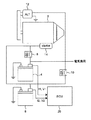
図1は、本発明の一実施形態に係る自動車のエンジンの制御装置を示す概略図である。本実施形態に係る自動車は、自動車の駆動源であるエンジン2と、エンジン2のスタータ14と車両用電気負荷とに電力を供給可能なメインバッテリ(第1のバッテリ)4及びサブバッテリ(第2のバッテリ)6と、自動車に搭載された種々の装置の動作を制御するECU(Electronic Control Unit)20とを備えている。
FIG. 1 is a schematic diagram showing an automobile engine control apparatus according to an embodiment of the present invention. The automobile according to the present embodiment includes an
また、本実施形態に係る自動車は、アイドルストップシステムを装備しており、駆動中のエンジン2は所定の停止条件が成立すると自動的に停止するように制御され、自動停止中のエンジン2は所定の復帰条件が成立すると自動的に再始動するように制御される。復帰条件は、発進操作に伴いエンジンを再始動させるための第1の復帰条件と、発進操作とは無関係にエンジンを再始動させるための第2の復帰条件とからなる。エンジン2の自動停止及び再始動に関する具体的な構成は後述する。
Further, the automobile according to the present embodiment is equipped with an idle stop system, and the
メインバッテリ4とサブバッテリ6は、図1に示すようにエンジン2のスタータ14、車両用電気負荷、及び発電機12に対して、所定箇所においては第1のリレー8又は/及び第2のリレー10を介して電気的に接続されている。
As shown in FIG. 1, the
例えばイグニッションキーの操作による通常のエンジン2の始動時は、第1のリレー8がオンで且つ第2のリレー10がオフになるように制御され、メインバッテリ4とサブバッテリ6の両者からエンジン2のスタータ14に電力が供給され、これによりスタータ14が駆動されてエンジン2が始動される。エンジン2の駆動中は、第1のリレー8と第2のリレー10が共にオフになるように制御され、メインバッテリ4のみから車両用電気負荷に電力が供給される。なお、エンジン2の駆動中においては、発電機12から供給される電力によりメインバッテリ4が充電される。エンジン2の自動停止中においても、エンジン2の駆動中と同様、第1のリレー8と第2のリレー10が共にオフになるように制御され、メインバッテリ4のみから車両用電気負荷に電力が供給される。自動停止中のエンジン2の再始動時は、第1のリレー8と第2のリレーが共にオフになるように制御され、サブバッテリ6のみからエンジン2のスタータ14に電力が供給され、これによりスタータ14が駆動されてエンジン2が再始動される。なお、エンジン2が再始動された後の所定時間、第2のリレー10がオンにされて、発電機12から供給される電力によりサブバッテリ6が充電される。
For example, when the
図2に示すように、ECU20には、自動車に搭載された種々の装置が電気的に接続されている。
As shown in FIG. 2, various devices mounted on the automobile are electrically connected to the
具体的に、ECU20に接続された装置のうち、ECU20へ向けて検出信号を出力する装置として、エンジン2の回転速度(単位時間当たりの回転数)Neを検出するエンジン回転速度センサ41、自動車の走行速度Sを検出する車速センサ42、アクセル開度θを検出するアクセル開度センサ43、車両用ブレーキのオン又はオフを検出するブレーキスイッチ44、メインバッテリ4から供給される電力の電圧V1を検出する電圧センサ45、メインバッテリ4から供給される電力の電流I1を検出する電流センサ46、サブバッテリ6から供給される電力の電圧V2を検出する電圧センサ47、サブバッテリ6から供給される電力の電流I2を検出する電流センサ48、及び自動変速機49が自動車に搭載されている。なお、電圧センサ45と電流センサ46はメインバッテリ4に内蔵され、電圧センサ47と電流センサ48はサブバッテリ6に内蔵されている。
Specifically, among the devices connected to the
一方、ECU20に接続された装置のうち、ECU20から送られる信号により制御される装置として、運転者に対して種々の報知を行う報知手段36、エンジン2の点火プラグ32、エンジン2への燃料供給を調整する燃料噴射弁34、及びエンジン2のスタータ14が含まれる。なお、報知手段36は、音声及び/又は表示により報知を行うように構成されている。
On the other hand, among the devices connected to the
ECU20は、エンジン2の自動停止中において発進操作とは無関係の第2の復帰条件が成立したとき、エンジン2を再始動するには安全上好ましくない状況にあるか否かを判定する状況判定部21と、状況判定部21により安全上好ましくない状況にあると判定されたとき、安全上好ましい状況になるまでエンジン2の再始動を禁止する再始動禁止部22と、自動変速機49から送られる信号に基づき自動変速機49の変速レンジを検出する変速レンジ検出部23と、エンジン2における燃料の燃焼を制御する燃焼制御部24と、エンジン2のスタータ14の駆動を制御するスタータ制御部26とを備えている。本実施形態において、安全上好ましくない状況とは、エンジン2が再始動したときに運転者の意思に反して自動車が発進し得る状況を指す。自動車が発進し得る状況とは、例えば、自動変速機49の変速レンジが走行レンジであり、且つ、車両用ブレーキがオフである状況を指す。
The
以下、アイドルストップシステムを用いた制御の具体例を説明する。 Hereinafter, a specific example of control using the idle stop system will be described.
[エンジンの自動停止制御]
図3を参照しながら、駆動中のエンジン2を自動的に停止させる制御の各処理の流れについて説明する。
[Automatic engine stop control]
With reference to FIG. 3, the flow of each process of control for automatically stopping the
図3に示すように、先ずステップS1〜ステップS3において、自動車の走行速度Sが車速センサ42により検出され、アクセル開度θがアクセル開度センサ43により検出され、車両用ブレーキのオン又はオフがブレーキスイッチ44により検出される。
As shown in FIG. 3, first, in step S1 to step S3, the traveling speed S of the automobile is detected by the
続くステップS4〜ステップS6では、エンジン2を自動的に停止させるための停止条件が成立しているか否かを確認するための処理が行われる。
In subsequent steps S4 to S6, processing for confirming whether or not a stop condition for automatically stopping the
具体的に、ステップS4では、ステップS1の検出に基づき、自動車の走行速度Sが0m/sであるか否かが判断される。ステップS4において走行速度Sが0m/sであると判断されると、ステップS5に進む。一方、ステップS4において走行速度Sが0m/sでないと判断され、停止条件が成立していないことが確認されると、エンジン2の燃料供給と点火がオンに維持された状態で(ステップS8)、図示しないメインルーチンに戻る。
Specifically, in step S4, based on the detection in step S1, it is determined whether or not the traveling speed S of the automobile is 0 m / s. If it is determined in step S4 that the traveling speed S is 0 m / s, the process proceeds to step S5. On the other hand, when it is determined in step S4 that the traveling speed S is not 0 m / s and it is confirmed that the stop condition is not satisfied, the fuel supply and ignition of the
ステップS5では、ステップS2の検出に基づき、アクセル開度θが0%であるか否か、すなわち、アクセルが全閉であるか否かが判断される。ステップS5においてアクセルが全閉であると判断されると、ステップS6に進む。一方、ステップS5においてアクセルが全閉でないと判断され、停止条件が成立していないことが確認されると、エンジン2の燃料供給と点火がオンに維持された状態で(ステップS8)、図示しないメインルーチンに戻る。
In step S5, based on the detection in step S2, it is determined whether or not the accelerator opening θ is 0%, that is, whether or not the accelerator is fully closed. If it is determined in step S5 that the accelerator is fully closed, the process proceeds to step S6. On the other hand, if it is determined in step S5 that the accelerator is not fully closed and it is confirmed that the stop condition is not satisfied, the fuel supply and ignition of the
ステップS6では、ステップS3の検出に基づき、車両用ブレーキがオンであるか否かが判断される。ステップS6においてブレーキがオンであると判断され、停止条件が成立したことが確認されると、ステップS7に進む。一方、ステップS6においてブレーキがオフであると判断され、停止条件が成立していないことが確認されると、エンジン2の燃料供給と点火がオンに維持された状態で(ステップS8)、図示しないメインルーチンに戻る。
In step S6, it is determined whether or not the vehicle brake is on based on the detection in step S3. If it is determined in step S6 that the brake is on and it is confirmed that the stop condition is satisfied, the process proceeds to step S7. On the other hand, if it is determined in step S6 that the brake is off and it is confirmed that the stop condition is not satisfied, the fuel supply and ignition of the
停止条件が成立すると、ステップS7において、エンジン2への燃料供給が停止されるように燃料噴射弁34が制御されるとともに、エンジン2の点火が停止されるように点火プラグ32が制御されて、これによりエンジン2が停止される。
When the stop condition is satisfied, in step S7, the
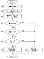
[エンジンの再始動制御]
続いて、図4を参照しながら、自動停止中のエンジン2を再始動させる制御の各処理の流れについて説明する。
[Engine restart control]
Next, the flow of each process of control for restarting the
図4に示すように、先ず、車両用ブレーキのオン又はオフがブレーキスイッチ44により検出され(ステップS11)、自動変速機49の変速レンジが変速レンジ検出部23により検出され(ステップS12)、車両用電気負荷へ電力供給中であるメインバッテリ4の電圧V1が検出される(ステップS13)。
As shown in FIG. 4, first, whether the vehicle brake is on or off is detected by the brake switch 44 (step S11), and the shift range of the
続くステップS14では、発進操作(運転者の発車意思)とは無関係にエンジン2を再始動させるための第2の復帰条件が成立したか否かを確認するため、ステップS13の検出に基づき、メインバッテリ4の電圧V1が所定電圧P以下に低下したか否かが判断される。ステップS14において、メインバッテリ4の電圧V1が所定電圧P以下であると判断され、第2の復帰条件が成立したことが確認されると、ステップS15に進む。一方、ステップS14において、メインバッテリ4の電圧V1が所定電圧Pよりも高いと判断され、第2の復帰条件が成立していないことが確認されると、ステップS19に進む。
In the following step S14, in order to confirm whether or not the second return condition for restarting the
第2の復帰条件が成立すると、ステップS15において、第1のリレー8がオンにされ、これにより、メインバッテリ4に加えてサブバッテリ6も車両用電気負荷に接続されて、ステップS16に進む。ステップS15の処理が行われると、メインバッテリ4とサブバッテリ6の両者から車両用電気負荷に電力が供給されるため、サブバッテリ6からの電力供給によりメインバッテリ4による電力供給量の低下を補うことができる。また、メインバッテリ4の過放電を回避することができる。
When the second return condition is satisfied, the
ステップS16とステップS17では、エンジン2を再始動するには安全上好ましくない状況にあるか否かが判定される。
In step S16 and step S17, it is determined whether or not it is in a situation unfavorable for safety to restart the
具体的に、ステップS16では、ステップS12の検出に基づき、自動変速機49の変速レンジが走行レンジであるか否かが判断される。ステップS16において、変速レンジが走行レンジ(例えばDレンジ)であると判断されると、安全上好ましくない状況にあるか否かの判定を引き続き行うため、ステップS17に進む。一方、ステップS16において、変速レンジが非走行レンジ(例えばNレンジ又はPレンジ)であると判断され、安全上好ましい状況にあることが確認されるとステップS20に進む。
Specifically, in step S16, based on the detection in step S12, it is determined whether or not the shift range of the
ステップS17では、ステップS11の検出に基づき、車両用ブレーキがオンであるか否かが判断される。ステップS17において、車両用ブレーキがオフであると判断されると、安全上好ましくない状況にあることが確認され、ステップS18に進む。一方、ステップS17において、車両用ブレーキがオンであると判断され、安全上好ましい状況にあることが確認されるとステップS20に進む。 In step S17, it is determined whether or not the vehicle brake is on based on the detection in step S11. If it is determined in step S17 that the vehicle brake is off, it is confirmed that the vehicle is in an unfavorable situation for safety, and the process proceeds to step S18. On the other hand, if it is determined in step S17 that the vehicle brake is on and it is confirmed that the vehicle is in a favorable situation for safety, the process proceeds to step S20.
ステップS18では、報知手段36により、安全上好ましい状況にするための操作を促す報知が運転者に対してなされる。具体的には、例えば、ブレーキペダルを踏み込む操作を促す報知が、音声及び/又は警告ランプの点灯によりなされる。かかる報知が行われることにより、運転者が速やかに適切な操作を行えば、エンジン2が再始動したときに運転者の意思に反して自動車が発進することを回避できる。
In step S18, the notification means 36 notifies the driver of an operation prompting an operation for obtaining a safety-preferred situation. Specifically, for example, notification that prompts the user to depress the brake pedal is made by sound and / or lighting of a warning lamp. By performing such notification, if the driver performs an appropriate operation promptly, it is possible to avoid starting the car against the driver's intention when the
ステップS18の報知が行われると、図示しないメインルーチンに戻り、安全上好ましい状況になるまで、上記判定(ステップS16及びステップS17)が繰り返し行われることでエンジン2の再始動が禁止される。よって、運転者の意思に反した自動車の発進を確実に防止することができる。
When the notification in step S18 is performed, the process returns to the main routine (not shown), and the above determination (step S16 and step S17) is repeatedly performed until the safety is favorable, thereby prohibiting restart of the
一方、第2の復帰条件が成立していない場合、発進操作に伴う第1の復帰条件が成立しているか否かを確認するため、ステップS19において、車両用ブレーキがオンであるか否かが判断される。ステップS19において、車両用ブレーキがオフであると判断され、第1の復帰条件が成立したことが確認されるとステップS20に進む。一方、ステップS19において、車両用ブレーキがオンであると判断され、第1の復帰条件も成立していないと判断されると、エンジン2が再始動されることなく、図示しないメインルーチンに戻る。
On the other hand, if the second return condition is not satisfied, whether or not the vehicle brake is on is determined in step S19 in order to confirm whether or not the first return condition associated with the start operation is satisfied. To be judged. In step S19, when it is determined that the vehicle brake is off and it is confirmed that the first return condition is satisfied, the process proceeds to step S20. On the other hand, if it is determined in step S19 that the vehicle brake is on and it is determined that the first return condition is not satisfied, the
第1の復帰条件が成立したことが確認された場合、又は、第2の復帰条件が成立し且つ安全上好ましい状況にあることが確認された場合、ステップS20において、エンジン2のスタータ14が駆動されるとともに、続くステップS21において、エンジン2の燃料供給及び点火が開始されるように燃料噴射弁34と点火プラグ32が制御される。これにより、安全が確実に確保された状態でエンジン2が再始動され、処理が終了する。
When it is confirmed that the first return condition is satisfied, or when it is confirmed that the second return condition is satisfied and the safety is favorable, in step S20, the
以上、上述の実施形態を挙げて本発明を説明したが、本発明は上述の実施形態に限定されるものではない。 While the present invention has been described with reference to the above-described embodiment, the present invention is not limited to the above-described embodiment.
例えば、上述の実施形態では、エンジンの再始動制御のステップS14(図4参照)において、メインバッテリ4の電圧V1が所定電圧P以下であるか否かを判断することで、第2の復帰条件が成立したか否かを確認する構成について説明したが、第2の復帰条件の成立の有無を確認するための構成は、これに限定されるものではない。具体的には、例えば、上述のステップS14において、自動車に搭載された空調装置の冷房機能が低下した否かを判断することで、第2の復帰条件の成立の有無を確認するようにしてもよい。この場合、空調装置の冷房機能が低下したか否かは、例えば、実際の車室内温度が空調装置の設定温度(目標の車室内温度)よりも所定温度以上高いか否かにより判断することが考えられる。
For example, in the above-described embodiment, the second return condition is determined by determining whether or not the voltage V1 of the
2:エンジン、4:メインバッテリ、6:サブバッテリ、14:スタータ、20:ECU、21:状況判定部、22:再始動禁止部、23:変速レンジ検出部、24:燃焼制御部、26:スタータ制御部、32:点火プラグ、34:燃料噴射弁、36:報知手段、41:エンジン回転速度センサ、42:車速センサ、43:アクセル開度センサ、44:ブレーキスイッチ、45:メインバッテリの電圧センサ、46:メインバッテリの電流センサ、47:サブバッテリの電圧センサ、48:サブバッテリの電流センサ、49:自動変速機。 2: engine, 4: main battery, 6: sub-battery, 14: starter, 20: ECU, 21: status determination unit, 22: restart prohibition unit, 23: shift range detection unit, 24: combustion control unit, 26: Starter control unit, 32: spark plug, 34: fuel injection valve, 36: notification means, 41: engine speed sensor, 42: vehicle speed sensor, 43: accelerator opening sensor, 44: brake switch, 45: voltage of main battery Sensor: 46: Current sensor of main battery, 47: Voltage sensor of sub battery, 48: Current sensor of sub battery, 49: Automatic transmission.
Claims (5)
エンジンの自動停止中において第2の復帰条件が成立したとき、エンジンを再始動するには安全上好ましくない状況にあるか否かを判定する状況判定手段と、
前記状況判定手段により安全上好ましくない状況にあると判定されたとき、安全上好ましい状況にするための操作を促す報知を運転者に対して行う報知手段と、
前記状況判定手段により安全上好ましくない状況にあると判定されたとき、安全上好ましい状況になるまでエンジンの再始動を禁止する再始動禁止手段と、を備えたことを特徴とするエンジンの制御装置。 When the vehicle engine is automatically stopped, the first return condition for restarting the engine with the start operation or the second return condition for restarting the engine irrespective of the start operation An engine control device that automatically restarts the engine when either of the above is established,
A condition determination means for determining whether or not the engine is in a situation unfavorable for safety when the second return condition is satisfied while the engine is automatically stopped;
When it is determined by the situation determination means that the situation is unfavorable for safety, an informing means for informing the driver of an operation for making a situation desirable for safety; and
And a restart prohibiting means for prohibiting restarting of the engine until the safety is favorable when it is determined by the situation determination means that the safety is not preferable. .
第2の復帰条件は、前記バッテリの電圧が所定電圧以下になることであることを特徴とする請求項1に記載のエンジンの制御装置。 The vehicle includes a battery that supplies power to the vehicle electrical load when the engine is automatically stopped,
The engine control apparatus according to claim 1, wherein the second return condition is that the voltage of the battery is equal to or lower than a predetermined voltage.
第2の復帰条件は、第1のバッテリの電圧が所定電圧以下になることであり、
第2の復帰条件が成立したとき、第2のバッテリから車両用電気負荷への電力供給を可能にすることを特徴とする請求項1に記載のエンジンの制御装置。 The vehicle supplies power to a first battery that supplies power to the vehicle electrical load when the engine is automatically stopped, and to the engine starter to restart the engine that is automatically stopped. A second battery to supply,
The second return condition is that the voltage of the first battery is equal to or lower than a predetermined voltage,
The engine control device according to claim 1, wherein when the second return condition is satisfied, electric power can be supplied from the second battery to the electric load for the vehicle.
車両用ブレーキの作動状態を検出するブレーキ検出手段とを備え、
前記状況判定手段は、前記レンジ検出手段により前記変速レンジが走行レンジであることが検出され、且つ、前記ブレーキ検出手段により車両用ブレーキが作動していないことが検出されたときに、安全上好ましくない状況にあると判定することを特徴とする請求項1〜3のいずれかに記載のエンジンの制御装置。 Range detecting means for detecting a shift range of the transmission;
Brake detecting means for detecting the operating state of the vehicle brake,
The situation determination means is preferable for safety when the range detection means detects that the shift range is a travel range and the brake detection means detects that the vehicle brake is not operating. The engine control apparatus according to claim 1, wherein it is determined that the engine is not in a situation.
Priority Applications (1)
| Application Number | Priority Date | Filing Date | Title |
|---|---|---|---|
| JP2008247387A JP5181975B2 (en) | 2008-09-26 | 2008-09-26 | Engine control device |
Applications Claiming Priority (1)
| Application Number | Priority Date | Filing Date | Title |
|---|---|---|---|
| JP2008247387A JP5181975B2 (en) | 2008-09-26 | 2008-09-26 | Engine control device |
Publications (2)
| Publication Number | Publication Date |
|---|---|
| JP2010077904A true JP2010077904A (en) | 2010-04-08 |
| JP5181975B2 JP5181975B2 (en) | 2013-04-10 |
Family
ID=42208611
Family Applications (1)
| Application Number | Title | Priority Date | Filing Date |
|---|---|---|---|
| JP2008247387A Expired - Fee Related JP5181975B2 (en) | 2008-09-26 | 2008-09-26 | Engine control device |
Country Status (1)
| Country | Link |
|---|---|
| JP (1) | JP5181975B2 (en) |
Cited By (6)
| Publication number | Priority date | Publication date | Assignee | Title |
|---|---|---|---|---|
| JP2012102664A (en) * | 2010-11-10 | 2012-05-31 | Mitsubishi Motors Corp | Vehicle control device |
| GB2489499A (en) * | 2011-03-31 | 2012-10-03 | Ford Global Tech Llc | A method and system for controlling restart of an engine |
| US8690729B2 (en) | 2010-12-07 | 2014-04-08 | Hyundai Motor Company | Method and device for controlling ISG logic |
| US8712673B2 (en) | 2010-12-06 | 2014-04-29 | Hyundai Motor Company | Idle stop and go system and method for controlling thereof |
| US8858396B2 (en) | 2010-12-07 | 2014-10-14 | Hyundai Motor Company | Device and method for controlling ISG logic |
| CN104295428A (en) * | 2013-07-18 | 2015-01-21 | 大陆汽车有限公司 | Method and apparatus for driving a starter motor |
Citations (4)
| Publication number | Priority date | Publication date | Assignee | Title |
|---|---|---|---|---|
| JPH06320989A (en) * | 1993-05-13 | 1994-11-22 | Iseki & Co Ltd | Liquid crystal display device for agricultural machinery |
| JP2000234538A (en) * | 1999-02-12 | 2000-08-29 | Mitsubishi Electric Corp | Engine stop and start controller |
| JP2003254208A (en) * | 2002-02-26 | 2003-09-10 | Toyota Motor Corp | Electric power control system for vehicle |
| JP2004169692A (en) * | 2002-10-28 | 2004-06-17 | Nissan Motor Co Ltd | Controlling device for vehicle |
-
2008
- 2008-09-26 JP JP2008247387A patent/JP5181975B2/en not_active Expired - Fee Related
Patent Citations (4)
| Publication number | Priority date | Publication date | Assignee | Title |
|---|---|---|---|---|
| JPH06320989A (en) * | 1993-05-13 | 1994-11-22 | Iseki & Co Ltd | Liquid crystal display device for agricultural machinery |
| JP2000234538A (en) * | 1999-02-12 | 2000-08-29 | Mitsubishi Electric Corp | Engine stop and start controller |
| JP2003254208A (en) * | 2002-02-26 | 2003-09-10 | Toyota Motor Corp | Electric power control system for vehicle |
| JP2004169692A (en) * | 2002-10-28 | 2004-06-17 | Nissan Motor Co Ltd | Controlling device for vehicle |
Cited By (9)
| Publication number | Priority date | Publication date | Assignee | Title |
|---|---|---|---|---|
| JP2012102664A (en) * | 2010-11-10 | 2012-05-31 | Mitsubishi Motors Corp | Vehicle control device |
| US8798894B2 (en) | 2010-11-10 | 2014-08-05 | Mitsubishi Jidosha Kogyo Kabushiki Kaisha | Vehicle control unit |
| US8712673B2 (en) | 2010-12-06 | 2014-04-29 | Hyundai Motor Company | Idle stop and go system and method for controlling thereof |
| US8690729B2 (en) | 2010-12-07 | 2014-04-08 | Hyundai Motor Company | Method and device for controlling ISG logic |
| US8858396B2 (en) | 2010-12-07 | 2014-10-14 | Hyundai Motor Company | Device and method for controlling ISG logic |
| GB2489499A (en) * | 2011-03-31 | 2012-10-03 | Ford Global Tech Llc | A method and system for controlling restart of an engine |
| US9366217B2 (en) | 2011-03-31 | 2016-06-14 | Ford Global Technologies, Llc | System and method for controlling engine restart operation to reduce resonance |
| GB2489499B (en) * | 2011-03-31 | 2016-08-24 | Ford Global Tech Llc | A method and system for controlling an engine |
| CN104295428A (en) * | 2013-07-18 | 2015-01-21 | 大陆汽车有限公司 | Method and apparatus for driving a starter motor |
Also Published As
| Publication number | Publication date |
|---|---|
| JP5181975B2 (en) | 2013-04-10 |
Similar Documents
| Publication | Publication Date | Title |
|---|---|---|
| US9764702B2 (en) | System and method for managing the electrical powering of at least one piece of equipment during the automatic restarting of an internal combustion engine of a vehicle | |
| JP4114666B2 (en) | Automatic stop control device for hybrid vehicle | |
| JP4437496B2 (en) | In-vehicle display controller | |
| US9234470B2 (en) | Idling stop device, power control method, deterioration notification method and battery charging method | |
| JP5181975B2 (en) | Engine control device | |
| JP2008137543A (en) | Vehicle, and its control method | |
| JP4983785B2 (en) | Electronic control device | |
| JP2007152983A (en) | Power control device for vehicle | |
| EP3333004B1 (en) | Power source control device and power source control method | |
| JP2015120462A (en) | Device for controlling vehicle | |
| JP2006220113A (en) | Engine controller | |
| JP2006217765A (en) | Vehicular dynamo controlling device | |
| JP3870903B2 (en) | Vehicle power supply control device | |
| JP4074629B2 (en) | Engine stop / start control device | |
| JP6054723B2 (en) | Engine start control device | |
| JP2015031270A (en) | Engine automatic stop/start control device | |
| JP2005120878A (en) | Idle stop vehicle | |
| JP2004222475A (en) | Power controller for vehicle | |
| JP5262518B2 (en) | Engine control device | |
| JP2008279854A (en) | Vehicle control device | |
| JP2003151600A (en) | Moving body using fuel cell as drive source | |
| JP2017008738A (en) | Engine starting device | |
| JP2006336521A (en) | Start determination device for vehicle and remote control device provided with same | |
| JP2006262552A (en) | Power unit | |
| JP2007100565A (en) | Engine starting control device |
Legal Events
| Date | Code | Title | Description |
|---|---|---|---|
| A621 | Written request for application examination |
Free format text: JAPANESE INTERMEDIATE CODE: A621 Effective date: 20110802 |
|
| A521 | Written amendment |
Free format text: JAPANESE INTERMEDIATE CODE: A523 Effective date: 20120329 |
|
| A131 | Notification of reasons for refusal |
Free format text: JAPANESE INTERMEDIATE CODE: A131 Effective date: 20120717 |
|
| A977 | Report on retrieval |
Free format text: JAPANESE INTERMEDIATE CODE: A971007 Effective date: 20120719 |
|
| A521 | Written amendment |
Free format text: JAPANESE INTERMEDIATE CODE: A523 Effective date: 20120906 |
|
| A131 | Notification of reasons for refusal |
Free format text: JAPANESE INTERMEDIATE CODE: A131 Effective date: 20120925 |
|
| A521 | Written amendment |
Free format text: JAPANESE INTERMEDIATE CODE: A523 Effective date: 20121126 |
|
| TRDD | Decision of grant or rejection written | ||
| A01 | Written decision to grant a patent or to grant a registration (utility model) |
Free format text: JAPANESE INTERMEDIATE CODE: A01 Effective date: 20121218 |
|
| A61 | First payment of annual fees (during grant procedure) |
Free format text: JAPANESE INTERMEDIATE CODE: A61 Effective date: 20121231 |
|
| R150 | Certificate of patent or registration of utility model |
Ref document number: 5181975 Country of ref document: JP Free format text: JAPANESE INTERMEDIATE CODE: R150 Free format text: JAPANESE INTERMEDIATE CODE: R150 |
|
| FPAY | Renewal fee payment (event date is renewal date of database) |
Free format text: PAYMENT UNTIL: 20160125 Year of fee payment: 3 |
|
| LAPS | Cancellation because of no payment of annual fees |