EP2500488A2 - Profilanordnung für ein Oberlicht - Google Patents
Profilanordnung für ein Oberlicht Download PDFInfo
- Publication number
- EP2500488A2 EP2500488A2 EP12159560A EP12159560A EP2500488A2 EP 2500488 A2 EP2500488 A2 EP 2500488A2 EP 12159560 A EP12159560 A EP 12159560A EP 12159560 A EP12159560 A EP 12159560A EP 2500488 A2 EP2500488 A2 EP 2500488A2
- Authority
- EP
- European Patent Office
- Prior art keywords
- profile
- motor
- assembly
- edge
- light
- Prior art date
- Legal status (The legal status is an assumption and is not a legal conclusion. Google has not performed a legal analysis and makes no representation as to the accuracy of the status listed.)
- Granted
Links
- 238000003780 insertion Methods 0.000 claims description 2
- 230000037431 insertion Effects 0.000 claims description 2
- 239000011521 glass Substances 0.000 description 4
- 239000004800 polyvinyl chloride Substances 0.000 description 4
- 229920000915 polyvinyl chloride Polymers 0.000 description 4
- XLYOFNOQVPJJNP-UHFFFAOYSA-N water Substances O XLYOFNOQVPJJNP-UHFFFAOYSA-N 0.000 description 4
- 229920003229 poly(methyl methacrylate) Polymers 0.000 description 3
- 239000004926 polymethyl methacrylate Substances 0.000 description 3
- 230000005611 electricity Effects 0.000 description 2
- 238000009434 installation Methods 0.000 description 2
- 239000000463 material Substances 0.000 description 2
- 239000004417 polycarbonate Substances 0.000 description 2
- 229920000515 polycarbonate Polymers 0.000 description 2
- 230000000712 assembly Effects 0.000 description 1
- 238000000429 assembly Methods 0.000 description 1
- 238000005452 bending Methods 0.000 description 1
- 239000002131 composite material Substances 0.000 description 1
- 238000001514 detection method Methods 0.000 description 1
- 238000009413 insulation Methods 0.000 description 1
- 238000012986 modification Methods 0.000 description 1
- 230000004048 modification Effects 0.000 description 1
- 230000002093 peripheral effect Effects 0.000 description 1
- 229920003023 plastic Polymers 0.000 description 1
- 239000004033 plastic Substances 0.000 description 1
- 229920000728 polyester Polymers 0.000 description 1
- -1 polyethylene terephthalate Polymers 0.000 description 1
- 239000005020 polyethylene terephthalate Substances 0.000 description 1
- 229920000139 polyethylene terephthalate Polymers 0.000 description 1
- SCUZVMOVTVSBLE-UHFFFAOYSA-N prop-2-enenitrile;styrene Chemical compound C=CC#N.C=CC1=CC=CC=C1 SCUZVMOVTVSBLE-UHFFFAOYSA-N 0.000 description 1
- 238000007789 sealing Methods 0.000 description 1
- 125000006850 spacer group Chemical group 0.000 description 1
- 229920000638 styrene acrylonitrile Polymers 0.000 description 1
- 210000002105 tongue Anatomy 0.000 description 1
Images


Classifications
-
- E—FIXED CONSTRUCTIONS
- E04—BUILDING
- E04D—ROOF COVERINGS; SKY-LIGHTS; GUTTERS; ROOF-WORKING TOOLS
- E04D13/00—Special arrangements or devices in connection with roof coverings; Protection against birds; Roof drainage ; Sky-lights
- E04D13/03—Sky-lights; Domes; Ventilating sky-lights
- E04D13/035—Sky-lights; Domes; Ventilating sky-lights characterised by having movable parts
- E04D13/0351—Sky-lights; Domes; Ventilating sky-lights characterised by having movable parts the parts pivoting about a fixed axis
- E04D13/0352—Sky-lights; Domes; Ventilating sky-lights characterised by having movable parts the parts pivoting about a fixed axis the parts being of domed or pyramidal shape
-
- E—FIXED CONSTRUCTIONS
- E04—BUILDING
- E04D—ROOF COVERINGS; SKY-LIGHTS; GUTTERS; ROOF-WORKING TOOLS
- E04D13/00—Special arrangements or devices in connection with roof coverings; Protection against birds; Roof drainage ; Sky-lights
- E04D13/03—Sky-lights; Domes; Ventilating sky-lights
- E04D13/0305—Supports or connecting means for sky-lights of flat or domed shape
- E04D13/0315—Supports or connecting means for sky-lights of flat or domed shape characterised by a curb frame
-
- E—FIXED CONSTRUCTIONS
- E04—BUILDING
- E04D—ROOF COVERINGS; SKY-LIGHTS; GUTTERS; ROOF-WORKING TOOLS
- E04D15/00—Apparatus or tools for roof working
- E04D15/04—Apparatus or tools for roof working for roof coverings comprising slabs, sheets or flexible material
-
- E—FIXED CONSTRUCTIONS
- E05—LOCKS; KEYS; WINDOW OR DOOR FITTINGS; SAFES
- E05F—DEVICES FOR MOVING WINGS INTO OPEN OR CLOSED POSITION; CHECKS FOR WINGS; WING FITTINGS NOT OTHERWISE PROVIDED FOR, CONCERNED WITH THE FUNCTIONING OF THE WING
- E05F11/00—Man-operated mechanisms for operating wings, including those which also operate the fastening
- E05F11/02—Man-operated mechanisms for operating wings, including those which also operate the fastening for wings in general, e.g. fanlights
- E05F11/04—Man-operated mechanisms for operating wings, including those which also operate the fastening for wings in general, e.g. fanlights with cords, chains or cables
- E05F11/06—Man-operated mechanisms for operating wings, including those which also operate the fastening for wings in general, e.g. fanlights with cords, chains or cables in guide-channels
-
- E—FIXED CONSTRUCTIONS
- E05—LOCKS; KEYS; WINDOW OR DOOR FITTINGS; SAFES
- E05F—DEVICES FOR MOVING WINGS INTO OPEN OR CLOSED POSITION; CHECKS FOR WINGS; WING FITTINGS NOT OTHERWISE PROVIDED FOR, CONCERNED WITH THE FUNCTIONING OF THE WING
- E05F15/00—Power-operated mechanisms for wings
- E05F15/60—Power-operated mechanisms for wings using electrical actuators
- E05F15/603—Power-operated mechanisms for wings using electrical actuators using rotary electromotors
- E05F15/611—Power-operated mechanisms for wings using electrical actuators using rotary electromotors for swinging wings
- E05F15/616—Power-operated mechanisms for wings using electrical actuators using rotary electromotors for swinging wings operated by push-pull mechanisms
- E05F15/619—Power-operated mechanisms for wings using electrical actuators using rotary electromotors for swinging wings operated by push-pull mechanisms using flexible or rigid rack-and-pinion arrangements
-
- E—FIXED CONSTRUCTIONS
- E05—LOCKS; KEYS; WINDOW OR DOOR FITTINGS; SAFES
- E05Y—INDEXING SCHEME ASSOCIATED WITH SUBCLASSES E05D AND E05F, RELATING TO CONSTRUCTION ELEMENTS, ELECTRIC CONTROL, POWER SUPPLY, POWER SIGNAL OR TRANSMISSION, USER INTERFACES, MOUNTING OR COUPLING, DETAILS, ACCESSORIES, AUXILIARY OPERATIONS NOT OTHERWISE PROVIDED FOR, APPLICATION THEREOF
- E05Y2201/00—Constructional elements; Accessories therefor
- E05Y2201/60—Suspension or transmission members; Accessories therefor
- E05Y2201/622—Suspension or transmission members elements
- E05Y2201/644—Flexible elongated pulling elements
- E05Y2201/656—Chains
-
- E—FIXED CONSTRUCTIONS
- E05—LOCKS; KEYS; WINDOW OR DOOR FITTINGS; SAFES
- E05Y—INDEXING SCHEME ASSOCIATED WITH SUBCLASSES E05D AND E05F, RELATING TO CONSTRUCTION ELEMENTS, ELECTRIC CONTROL, POWER SUPPLY, POWER SIGNAL OR TRANSMISSION, USER INTERFACES, MOUNTING OR COUPLING, DETAILS, ACCESSORIES, AUXILIARY OPERATIONS NOT OTHERWISE PROVIDED FOR, APPLICATION THEREOF
- E05Y2900/00—Application of doors, windows, wings or fittings thereof
- E05Y2900/10—Application of doors, windows, wings or fittings thereof for buildings or parts thereof
- E05Y2900/13—Type of wing
- E05Y2900/148—Windows
- E05Y2900/152—Roof windows
- E05Y2900/154—Skylights
Definitions
- the present invention relates to a profile assembly for use in a roof light element, such as a roof window or a dome skylight.
- a profile assembly typically comprises a number of mutually connecting edge profiles intended to extend along the periphery of at least one light-transmitting element such as a panel and/or a dome element. These edge profiles are further adapted to be connected to this at least one light-transmitting element.
- Such profile assemblies are used in opening roof light elements. It is known to build a motor into an upstand. Using such a motor built into the upstand the profile assembly can be raised from the upstand in order to open the roof light element. Such an embodiment in which the motor is built into the upstand has the drawback that a recess has to be cut into the upstand, and that in the open position of the roof light element water and/or dirt can enter the chamber in which the motor is situated.
- the object of the present invention is to provide a profile assembly and roof light assembly of the type stated in the preamble which can better withstand rain and enable a simple installation and/or replacement of a roof light element.
- the profile assembly according to the invention is distinguished for this purpose in that a first edge profile of the number of mutually connecting edge profiles is provided with a hollow chamber, and that a motor or a cylinder is received in the hollow chamber.
- An elongate support element movable by the motor or the cylinder protrudes through an underside of the edge profile and has an end intended for connection to the upstand.
- the motor or the cylinder can raise the profile assembly with the at least one light-transmitting element from the upstand by moving the elongate support element outward such that the roof light element is opened.
- the motor or cylinder is thus built into a frame which bears the at least one light-transmitting element and is consequently invisible when the roof light element is open or closed.
- the motor or cylinder is thus placed as it were upside down and is raised together with the frame formed by the edge profiles and the at least one light-transmitting element.
- the motor or cylinder can for instance be inserted into the first edge profile before joining the mutually connecting edge profiles to each other.
- the motor or cylinder is in this way not exposed to driving rain and there is consequently no danger of short-circuit.
- the profile assembly with the at least one light-transmitting element can further be wholly assembled in the factory such that no cutting work is required during placing of the roof light element. Installation will therefore be quite simple.
- existing roof light elements can easily be replaced by a roof light element with a profile assembly according to the invention without breaking work being necessary.
- a motor typically an electric motor
- the elongate support element is a chain, a gear rack or a spindle.
- a cylinder typically a pneumatic cylinder
- the elongate support element is a piston rod or a stiff element coupled thereto.
- the elongate support element is a chain which is flexible in one plane but stiff in any other plane. Motors with such a chain have the advantage of being quite compact and inexpensive.
- the motor is preferably mounted in the edge profile such that the plane in which the chain is to some extent flexible is parallel to the edge profile.
- the hollow chamber has dimensions which are larger than the dimensions of the motor. More particularly, the first edge profile is preferably adapted such that the motor is tiltable to limited extent relative to the first edge profile.
- the first edge profile has a longitudinal direction and the hollow chamber is bounded by two side walls extending in the longitudinal direction, wherein a support flange extending in the longitudinal direction is provided at a distance from the side walls at the bottom of the hollow chamber. The distance between the side walls is preferably greater than the width of the motor. In this way the motor will, in the closed position of the roof light element, be tiltable to limited extent around the support flange, which is preferably a relatively narrow flange.
- the hollow chamber preferably further has an inclining upper wall which extends between the two side walls and which runs inclining upward from an outer wall of the first edge profile to an inner wall thereof.
- the motor will in this way be able to tilt relative to the upper wall during the movement from the open to the closed position.
- a second edge profile intended for placing opposite the first edge profile is adapted to be connected hingedly to the upstand.
- a profile assembly is provided with four edge profiles, each provided at the underside thereof with a cable duct extending in the lengthwise direction thereof for receiving a power supply cable, for instance an electrical cable for powering the motor, or a pneumatic cable for powering a pneumatic cylinder.
- a power supply cable for instance an electrical cable for powering the motor, or a pneumatic cable for powering a pneumatic cylinder.
- Such a cable duct can be provided with a longitudinal opening bounded by a flexible flange. This flexible flange is dimensioned such that a power supply cable can be introduced and held in the cable duct. It will in this way be possible to carry a power supply cable from the motor or cylinder via the cable duct to a second edge profile connected hingedly to the upstand and connect the cable from here to a power source, for instance the mains electricity in the case of an electrical cable.
- the invention further relates to a roof light assembly comprising an embodiment of a profile assembly as described above and at least one light-transmitting element such as a panel or a dome element.
- each edge profile is provided with a support flange for a light-transmitting plate.
- This support flange preferably extends from the inner wall of the edge profile, still more preferably substantially in line with the upper wall of the edge profile.
- a light-transmitting plate can then be fixed against the underside of this support flange.
- the inner wall of an edge profile can further be adapted for connection to a clamping profile.
- One or more light-transmitting plates can in this way be received between such a clamping profile and the support flange.
- each edge profile a clamping profile which is connectable to the inner wall of the edge profile, wherein at least one light-transmitting plate is received between this clamping profile and the support flange.
- At least one light-transmitting dome element is mounted on the upper walls of the mutually connecting edge profiles.
- the light-transmitting dome element is provided at its periphery with a peripheral flange directed inclining downward and extending along the outer wall of each edge profile.
- one or more light-transmitting dome elements can be mounted on the upper walls of the edge profiles. Note that such light-transmitting dome elements can be used in combination with light-transmitting plates, but can also be arranged on the edge profiles without the light-transmitting plates.
- a light-transmitting element as stated above can be a light-transmitting plate-like element or a light-transmitting dome element.
- a light-transmitting element can for instance be manufactured from glass or from plastic.
- the light-transmitting element can more particularly be manufactured from for instance polycarbonate, polymethyl methacrylate, styrene acrylonitrile, glass fibre-reinforced polyester, polyethylene terephthalate, polyvinyl chloride or the like.
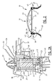
- Figure 1 shows a dome assembly 1 with a light-transmitting dome element 3 mounted on a profile assembly 2 extending along the periphery of the light-transmitting dome element 3.
- a light-transmitting plate can also be used instead of a light-transmitting dome element 3 such that a roof window is formed.
- a single or multi-walled light-transmitting dome element 3 can further be combined with one or more light-transmitting plate elements, see for instance the embodiment of figure 2 .
- the profile assembly 2 forms a frame which is connected on one side to upstand 4 for pivoting around an axis A. Note that the term upstand should be interpreted broadly as being any possible support for frame 2.
- One or more motors or cylinders 5 are received in frame 2.
- Each motor or cylinder is provided with an elongate support element 6 which is movable by the motor and which protrudes outward through an underside of frame 2 and is connected to upstand 4.
- the motors or cylinders 5 can in this way raise the profile assembly 2 with dome element 3 and/or light-transmitting plate from upstand 4 by moving outward from frame 2 the elongate support elements 6 connected at their outer end to upstand 4.
- FIG. 2 illustrates in cross-section a dome assembly 10 with a frame 20 consisting of four mutually connected edge profiles, of which a first edge profile 21 and a second edge profile 27 are shown.
- Frame 20 supports on the one hand the dome 30 consisting of a first dome wall 33 and a second dome wall 34 and on the other a two-walled light-transmitting plate 31, 32.
- the same frame 20 can be used with only one or more dome walls without the light-transmitting plates 31, 32.
- Frame 20 can also be used with only one or more light-transmitting plates 31, 32 without dome elements 33, 34.
- Frame 20 is supported on an upstand 40 and is connected hingedly on one side 41 to upstand 40.
- a motor 5 is received in frame 20 on the other side 41.
- the cross-section shown in figures 2, 2A , 3 and 3A is taken at the position of a motor built into frame 20. Note that, in accordance with the dimensions of dome assembly 10, one or more motors can be built into frame 20.
- the first edge profile 21 is provided with a hollow chamber 22 in which motor 5 is received.
- An elongate support element 6, here a chain, movable by the motor protrudes through the underside of the first edge profile 21 and is connected to upstand 40, typically by means of a fixing plate 43.
- the motor and the elongate element movable by the motor are embodied here as a chain motor, although the skilled person will appreciate that a similar configuration is possible with a spindle motor or a gear rack motor or with a cylinder.
- Chain 6 is typically a chain which is flexible in one plane and otherwise stiff. Chain 6 is flexible in a plane parallel to the first edge profile.
- the first edge profile 21 on the other side 42 will make a circular movement during opening of the dome.
- Chain 6, which has rigid characteristics in the plane of the circular movement, will require that the motor can tilt to some extent in hollow chamber 22, see figure 3 .
- the first edge profile 21 is after all mounted rigidly in dome assembly 10 and so follows the circular movement.
- hollow chamber 22 dimensions which are larger than the dimensions of motor 5 the motor 5 can take up different positions relative to the first edge profile 21.
- motor 5 When the dome is opened, motor 5 will typically come to lie at less of an incline than the other part of the first edge profile 21.
- a support flange 23 which extends in the longitudinal direction of the first edge profile 21 at a distance from the side walls 24, 25 bounding hollow chamber 22.
- the distance between side walls 24, 25 is preferably slightly greater than the width of motor 5.
- a second edge profile 27 extends parallel to the first edge profile 21 and is provided with connecting means for hinged connection of the second edge profile 27 to upstand 40.
- the first edge profile 21 is typically connected to the second edge profile 27 via a third and a fourth edge profile such that a frame 20 is formed along the periphery of the transmitting panels/dome elements 31-34.
- These first, second, third and fourth edge profiles are preferably embodied in substantially the same manner such that they can be easily welded to each other at the corners.
- the edge profiles are preferably provided with a cable duct for a power supply cable, for instance an electrical cable in the case of a motor or a compressed air cable in the case of a cylinder.
- a cable duct 28 in which power supply cables can be arranged along the underside thereof.
- the underside of cable duct 28 is preferably embodied with a flexible flange 29 which is dimensioned and adapted to enable the insertion and holding of a power supply cable in the cable duct.
- This flexible flange is preferably a flange of a soft PVC material.
- a power supply cable for the electric motor or cylinder 5 can in this way be carried, in a manner which is convenient and invisible from outside, from the electric motor or cylinder to the hinge side 41, where the power supply cable can for instance be connected through upstand 40 to the mains electricity in the case of an electric motor.
- On the underside of the first edge profile 21 a number of flexible sealing tongues 51, 52, 53 can further be provided which can for instance be manufactured from a soft PVC material.
- the first edge profile has a lower wall 64, an upper wall 63, an outer wall 61 and an inner wall 62.
- Outer wall 61 preferably has on its underside a portion bending away outward which provides for a good drainage.
- inner wall 62 is a support flange 65 extending substantially in the line of upper wall 63 and on the other grooves 66, 67 in which a clamping profile 68 can be secured. Glass plates 31, 32 can in this way be received, with interposing of a spacer 35, between support flange 65 and clamping profile 68.
- the use of such a support flange 65 in line with upper wall 63 has particular advantages when the roof assembly is used without dome elements 33, 34. The use of such a support flange will enable easy drainage of water present on glass plate 32 when the roof assembly is placed at a slight incline.
- Dome elements 33, 34 are preferably mounted on the upper wall 63 of the first edge profile 21.
- the outer dome element 33 is preferably further provided with a downward directed inclining portion 36 for the purpose of forming a suitable drainage.
- Dome elements 33, 34 can be mounted against upper wall 63 in known manner using mounting means 37.
- the first, second, third and fourth edge profiles are preferably embodied in similar manner and are preferably provided with a chamber structure between the lower wall 64, upper wall 63, inner wall 62 and outer wall 61 on the one hand and hollow chamber 22 on the other. This imparts the necessary strength to the edge profiles and also provides for good insulation.
- Dome elements 33, 34 can for instance be manufactured from polymethyl methacrylate (PMMA) or polycarbonate or the like.
- Upstand 40 and edge profiles 21 can for instance be manufactured from PVC or from a composite material.
- the light-transmitting panel elements 31, 32 can for instance be a double burglar-proof HE++ security glazing.
- a receiver connected to the motor is preferably further provided in frame 20 for receiving signals from a remote control for operating the motor.
- Frame 20 or the upstand can further be provided with a battery powered by one or more solar cells for the purpose of driving the motor 5. These solar cells can for instance be placed on the roof and connected to the battery.
- the battery need not be accommodated in the frame or the upstand and can also be incorporated in other manner in another structure. Wind and/or rain detection means can also be provided for automatic control of the motor in order to close the dome automatically for instance in the case of heavy rainfall.
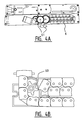
- FIGS. 4A and 4B show a possible embodiment of a chain motor which can be used in a profile assembly according to the invention.
- This is a motor from the Topp Spa company with a chain 6 driven by a toothed wheel 60 which is driven by the motor via a number of toothed wheels 61 (only a few toothed wheels are visible in the figures).
Landscapes
- Engineering & Computer Science (AREA)
- Architecture (AREA)
- Civil Engineering (AREA)
- Structural Engineering (AREA)
- Power-Operated Mechanisms For Wings (AREA)
- Non-Portable Lighting Devices Or Systems Thereof (AREA)
Priority Applications (1)
| Application Number | Priority Date | Filing Date | Title |
|---|---|---|---|
| PL12159560T PL2500488T3 (pl) | 2011-03-18 | 2012-03-15 | Zespół świetlika kopułowego |
Applications Claiming Priority (1)
| Application Number | Priority Date | Filing Date | Title |
|---|---|---|---|
| BE2011/0171A BE1019311A4 (nl) | 2011-03-18 | 2011-03-18 | Profielsamenstel voor een daklichtelement. |
Publications (3)
| Publication Number | Publication Date |
|---|---|
| EP2500488A2 true EP2500488A2 (de) | 2012-09-19 |
| EP2500488A3 EP2500488A3 (de) | 2012-11-07 |
| EP2500488B1 EP2500488B1 (de) | 2014-11-05 |
Family
ID=45808357
Family Applications (1)
| Application Number | Title | Priority Date | Filing Date |
|---|---|---|---|
| EP12159560.7A Not-in-force EP2500488B1 (de) | 2011-03-18 | 2012-03-15 | Kuppelförmige Oberlichtanordnung |
Country Status (6)
| Country | Link |
|---|---|
| EP (1) | EP2500488B1 (de) |
| BE (1) | BE1019311A4 (de) |
| DK (1) | DK2500488T3 (de) |
| ES (1) | ES2528048T3 (de) |
| PL (1) | PL2500488T3 (de) |
| PT (1) | PT2500488E (de) |
Cited By (8)
| Publication number | Priority date | Publication date | Assignee | Title |
|---|---|---|---|---|
| EP2778313A1 (de) * | 2013-03-15 | 2014-09-17 | Zet Yapi Ürünleri Insaat ve Ticaret Anonim Sirketi | Polycarbonat-Dachoberlicht mit Zwickelform |
| EP2868831A1 (de) * | 2013-10-31 | 2015-05-06 | JET Tageslicht und RWA GmbH | Lichtkuppel, Klappe und/oder Rauchabzugseinrichtung |
| JP2015098698A (ja) * | 2013-11-19 | 2015-05-28 | 大日本プラスチックス株式会社 | 採光装置改修方法、および、改修採光装置 |
| DE202016107225U1 (de) | 2016-12-21 | 2017-10-10 | Aumüller Aumatic GmbH | Lichtdurchlässiger Öffnungsverschluss für Gebäude |
| EP3199718B1 (de) | 2016-01-27 | 2018-05-09 | VKR Holding A/S | Flachdach-oberlicht und ein witterungsschutz dafür |
| EP3779088A1 (de) * | 2020-02-03 | 2021-02-17 | VKR Holding A/S | Klappfenster mit einem igu in der nähe des fensterrahmens |
| EP4006254A1 (de) * | 2020-11-27 | 2022-06-01 | VKR Holding A/S | Dachfenster umfassend einen flügel mit äusserem wetterschutzschild |
| EP4006253A1 (de) * | 2020-11-27 | 2022-06-01 | VKR Holding A/S | Dachfenster umfassend einen flügel mit aufklappbarem äusseren wetterschutzschild |
Families Citing this family (8)
| Publication number | Priority date | Publication date | Assignee | Title |
|---|---|---|---|---|
| BE1026397B1 (nl) | 2018-06-19 | 2020-01-30 | Skylux Nv | Verbeterde werkwijze voor het vervaardigen van een meerwandige module, in het bijzonder een meerwandige dakinrichting |
| BE1026789B1 (nl) | 2018-11-16 | 2020-06-18 | Skylux Nv | Werkwijze voor het vervaardigen van een meerwandige inrichting, in het bijzonder een meerwandige dakinrichting |
| BE1027818B1 (nl) | 2019-11-29 | 2021-07-01 | Skylux Nv | Dak- of raamsamenstel met inzetstuk |
| BE1027870B1 (nl) | 2019-12-17 | 2021-07-14 | Skylux Nv | Verbeterde werkwijze voor het vervaardigen van een meerwandige module, in het bijzonder een meerwandige dakinrichting |
| BE1027925B1 (nl) | 2019-12-26 | 2021-08-03 | Skylux Nv | Werkwijze voor het vervaardigen van een meerwandige module |
| BE1027927B1 (nl) | 2019-12-27 | 2021-08-03 | Skylux Nv | Vacuum koepelinrichting en werkwijze voor het vervaardigen daarvan |
| EP3779095B1 (de) | 2020-02-03 | 2022-06-29 | VKR Holding A/S | Ein dachfenster |
| BE1029229B1 (nl) | 2021-03-22 | 2022-10-18 | Skylux N V | Dak- of raamsamenstel met inzetstuk |
Family Cites Families (7)
| Publication number | Priority date | Publication date | Assignee | Title |
|---|---|---|---|---|
| DE4131762C2 (de) * | 1991-09-24 | 1997-05-22 | Winkhaus Fa August | Betätigungsvorrichtung für einen Flügel eines Fensters, einer Tür, einer Lüftungsklappe oder dergleichen |
| DE19534614A1 (de) * | 1995-09-18 | 1997-03-20 | Winkhaus Fa August | Sicherheitssperreinrichtung für eine Betätigungsvorrichtung zum Öffnen und Schließen eines Flügels eines Fensters, einer Tür, einer Lüftungsklappe oder dergleichen |
| DE29604692U1 (de) * | 1996-03-15 | 1996-05-02 | Aug. Winkhaus GmbH & Co. KG, 48291 Telgte | Vorrichtung zum Auslenken einer drehbeweglich angeordneten Baueinheit, insbesondere eines Fensters |
| WO2001094732A1 (en) * | 2000-06-09 | 2001-12-13 | Vkr Holding A/S | A window operator |
| EP1813757B1 (de) * | 2006-01-25 | 2012-02-22 | VKR Holding A/S | Kettenschubantrieb für Fenster |
| US8191317B2 (en) * | 2008-07-25 | 2012-06-05 | Vkr Holding A/S | Ventilated curb-mount skylight with separable hinge |
| DE102009024409B4 (de) * | 2009-06-09 | 2018-06-21 | Heinrich Strunz Gmbh | Faserverstärktes Kunststoffbauteil mit mikroverkapseltem Phasenwechselmaterial |
-
2011
- 2011-03-18 BE BE2011/0171A patent/BE1019311A4/nl active
-
2012
- 2012-03-15 DK DK12159560.7T patent/DK2500488T3/en active
- 2012-03-15 PT PT121595607T patent/PT2500488E/pt unknown
- 2012-03-15 PL PL12159560T patent/PL2500488T3/pl unknown
- 2012-03-15 ES ES12159560.7T patent/ES2528048T3/es active Active
- 2012-03-15 EP EP12159560.7A patent/EP2500488B1/de not_active Not-in-force
Non-Patent Citations (1)
| Title |
|---|
| None |
Cited By (8)
| Publication number | Priority date | Publication date | Assignee | Title |
|---|---|---|---|---|
| EP2778313A1 (de) * | 2013-03-15 | 2014-09-17 | Zet Yapi Ürünleri Insaat ve Ticaret Anonim Sirketi | Polycarbonat-Dachoberlicht mit Zwickelform |
| EP2868831A1 (de) * | 2013-10-31 | 2015-05-06 | JET Tageslicht und RWA GmbH | Lichtkuppel, Klappe und/oder Rauchabzugseinrichtung |
| JP2015098698A (ja) * | 2013-11-19 | 2015-05-28 | 大日本プラスチックス株式会社 | 採光装置改修方法、および、改修採光装置 |
| EP3199718B1 (de) | 2016-01-27 | 2018-05-09 | VKR Holding A/S | Flachdach-oberlicht und ein witterungsschutz dafür |
| DE202016107225U1 (de) | 2016-12-21 | 2017-10-10 | Aumüller Aumatic GmbH | Lichtdurchlässiger Öffnungsverschluss für Gebäude |
| EP3779088A1 (de) * | 2020-02-03 | 2021-02-17 | VKR Holding A/S | Klappfenster mit einem igu in der nähe des fensterrahmens |
| EP4006254A1 (de) * | 2020-11-27 | 2022-06-01 | VKR Holding A/S | Dachfenster umfassend einen flügel mit äusserem wetterschutzschild |
| EP4006253A1 (de) * | 2020-11-27 | 2022-06-01 | VKR Holding A/S | Dachfenster umfassend einen flügel mit aufklappbarem äusseren wetterschutzschild |
Also Published As
| Publication number | Publication date |
|---|---|
| PT2500488E (pt) | 2015-02-06 |
| EP2500488A3 (de) | 2012-11-07 |
| ES2528048T3 (es) | 2015-02-03 |
| BE1019311A4 (nl) | 2012-05-08 |
| EP2500488B1 (de) | 2014-11-05 |
| DK2500488T3 (en) | 2015-02-16 |
| PL2500488T3 (pl) | 2015-04-30 |
Similar Documents
| Publication | Publication Date | Title |
|---|---|---|
| EP2500488B1 (de) | Kuppelförmige Oberlichtanordnung | |
| EP3348737A1 (de) | Dachfenster insbesondere für flachdächer | |
| US20140021903A1 (en) | Windows and doors having integrated solar powered charging devices | |
| FR2776023B1 (fr) | Inverseur de poussee de turboreacteur a portes formant ecopes associees a une grille mobile | |
| WO2007092027A3 (en) | An illuminated window blind assembly | |
| JP2010203156A (ja) | 天窓装置 | |
| EP3384117A1 (de) | System zur automatisierung einer jalousie mit schiebepaneelen und verfahren zur nachrüstung davon | |
| JP2018048525A (ja) | 建築用開閉装置における防水構造 | |
| EP2597245B1 (de) | Anbringungselemente für ein Fenster und die zugehörige Verdunkelungseinrichtung | |
| KR200462893Y1 (ko) | 건축물 지붕용 아치형 채광기 | |
| CN204899055U (zh) | 自动天窗 | |
| KR20170049947A (ko) | 창문과 출입문을 갖는 돔하우스 | |
| KR101209773B1 (ko) | 층방용 태양전지 플레이트구조 | |
| KR102819310B1 (ko) | 썬룸 | |
| JPH054548Y2 (de) | ||
| WO2012001540A2 (en) | Building window structure | |
| JP2021165474A (ja) | 太陽光パネルユニットおよび建築部材 | |
| JP2018048524A (ja) | 建築用開閉装置における防水パネルおよび該防水パネルの組立て方法 | |
| CN217897045U (zh) | 一种天窗组件 | |
| CN214785444U (zh) | 一种防水屋面用铺设装置 | |
| CN219281173U (zh) | 一种地下建筑通风采光井 | |
| CN221236627U (zh) | 一种可遥控的智能窗 | |
| CN116838035B (zh) | 一种四边均可外部转动开启的采光顶构造 | |
| CN214090542U (zh) | 一种可智能开合的移动采光顶 | |
| EP2154327B1 (de) | Verbessertes Tor |
Legal Events
| Date | Code | Title | Description |
|---|---|---|---|
| PUAI | Public reference made under article 153(3) epc to a published international application that has entered the european phase |
Free format text: ORIGINAL CODE: 0009012 |
|
| AK | Designated contracting states |
Kind code of ref document: A2 Designated state(s): AL AT BE BG CH CY CZ DE DK EE ES FI FR GB GR HR HU IE IS IT LI LT LU LV MC MK MT NL NO PL PT RO RS SE SI SK SM TR |
|
| AX | Request for extension of the european patent |
Extension state: BA ME |
|
| PUAL | Search report despatched |
Free format text: ORIGINAL CODE: 0009013 |
|
| AK | Designated contracting states |
Kind code of ref document: A3 Designated state(s): AL AT BE BG CH CY CZ DE DK EE ES FI FR GB GR HR HU IE IS IT LI LT LU LV MC MK MT NL NO PL PT RO RS SE SI SK SM TR |
|
| AX | Request for extension of the european patent |
Extension state: BA ME |
|
| RIC1 | Information provided on ipc code assigned before grant |
Ipc: E05F 15/12 20060101ALI20120928BHEP Ipc: E04D 15/04 20060101ALI20120928BHEP Ipc: E05F 11/06 20060101ALI20120928BHEP Ipc: E04D 13/035 20060101AFI20120928BHEP |
|
| 17P | Request for examination filed |
Effective date: 20130506 |
|
| 17Q | First examination report despatched |
Effective date: 20130813 |
|
| GRAP | Despatch of communication of intention to grant a patent |
Free format text: ORIGINAL CODE: EPIDOSNIGR1 |
|
| GRAJ | Information related to disapproval of communication of intention to grant by the applicant or resumption of examination proceedings by the epo deleted |
Free format text: ORIGINAL CODE: EPIDOSDIGR1 |
|
| GRAP | Despatch of communication of intention to grant a patent |
Free format text: ORIGINAL CODE: EPIDOSNIGR1 |
|
| INTG | Intention to grant announced |
Effective date: 20140507 |
|
| INTG | Intention to grant announced |
Effective date: 20140528 |
|
| GRAS | Grant fee paid |
Free format text: ORIGINAL CODE: EPIDOSNIGR3 |
|
| GRAA | (expected) grant |
Free format text: ORIGINAL CODE: 0009210 |
|
| AK | Designated contracting states |
Kind code of ref document: B1 Designated state(s): AL AT BE BG CH CY CZ DE DK EE ES FI FR GB GR HR HU IE IS IT LI LT LU LV MC MK MT NL NO PL PT RO RS SE SI SK SM TR |
|
| REG | Reference to a national code |
Ref country code: GB Ref legal event code: FG4D |
|
| REG | Reference to a national code |
Ref country code: CH Ref legal event code: EP |
|
| REG | Reference to a national code |
Ref country code: AT Ref legal event code: REF Ref document number: 694753 Country of ref document: AT Kind code of ref document: T Effective date: 20141115 |
|
| REG | Reference to a national code |
Ref country code: IE Ref legal event code: FG4D |
|
| REG | Reference to a national code |
Ref country code: DE Ref legal event code: R096 Ref document number: 602012003623 Country of ref document: DE Effective date: 20141224 |
|
| REG | Reference to a national code |
Ref country code: CH Ref legal event code: NV Representative=s name: ARNOLD AND SIEDSMA AG, CH |
|
| REG | Reference to a national code |
Ref country code: RO Ref legal event code: EPE |
|
| REG | Reference to a national code |
Ref country code: ES Ref legal event code: FG2A Ref document number: 2528048 Country of ref document: ES Kind code of ref document: T3 Effective date: 20150203 |
|
| REG | Reference to a national code |
Ref country code: PT Ref legal event code: SC4A Free format text: AVAILABILITY OF NATIONAL TRANSLATION Effective date: 20150126 |
|
| REG | Reference to a national code |
Ref country code: NL Ref legal event code: T3 |
|
| REG | Reference to a national code |
Ref country code: DK Ref legal event code: T3 Effective date: 20150209 |
|
| REG | Reference to a national code |
Ref country code: SE Ref legal event code: TRGR |
|
| REG | Reference to a national code |
Ref country code: EE Ref legal event code: FG4A Ref document number: E010197 Country of ref document: EE Effective date: 20150114 |
|
| REG | Reference to a national code |
Ref country code: FR Ref legal event code: PLFP Year of fee payment: 4 |
|
| REG | Reference to a national code |
Ref country code: SK Ref legal event code: T3 Ref document number: E 17928 Country of ref document: SK |
|
| PG25 | Lapsed in a contracting state [announced via postgrant information from national office to epo] |
Ref country code: IS Free format text: LAPSE BECAUSE OF FAILURE TO SUBMIT A TRANSLATION OF THE DESCRIPTION OR TO PAY THE FEE WITHIN THE PRESCRIBED TIME-LIMIT Effective date: 20150305 Ref country code: FI Free format text: LAPSE BECAUSE OF FAILURE TO SUBMIT A TRANSLATION OF THE DESCRIPTION OR TO PAY THE FEE WITHIN THE PRESCRIBED TIME-LIMIT Effective date: 20141105 Ref country code: NO Free format text: LAPSE BECAUSE OF FAILURE TO SUBMIT A TRANSLATION OF THE DESCRIPTION OR TO PAY THE FEE WITHIN THE PRESCRIBED TIME-LIMIT Effective date: 20150205 |
|
| PGFP | Annual fee paid to national office [announced via postgrant information from national office to epo] |
Ref country code: EE Payment date: 20150325 Year of fee payment: 4 Ref country code: BG Payment date: 20150326 Year of fee payment: 4 Ref country code: IT Payment date: 20150331 Year of fee payment: 4 Ref country code: CH Payment date: 20150327 Year of fee payment: 4 Ref country code: DK Payment date: 20150331 Year of fee payment: 4 Ref country code: IE Payment date: 20150326 Year of fee payment: 4 Ref country code: ES Payment date: 20150325 Year of fee payment: 4 Ref country code: LU Payment date: 20150325 Year of fee payment: 4 |
|
| REG | Reference to a national code |
Ref country code: PL Ref legal event code: T3 |
|
| PG25 | Lapsed in a contracting state [announced via postgrant information from national office to epo] |
Ref country code: CY Free format text: LAPSE BECAUSE OF FAILURE TO SUBMIT A TRANSLATION OF THE DESCRIPTION OR TO PAY THE FEE WITHIN THE PRESCRIBED TIME-LIMIT Effective date: 20141105 Ref country code: HR Free format text: LAPSE BECAUSE OF FAILURE TO SUBMIT A TRANSLATION OF THE DESCRIPTION OR TO PAY THE FEE WITHIN THE PRESCRIBED TIME-LIMIT Effective date: 20141105 Ref country code: GR Free format text: LAPSE BECAUSE OF FAILURE TO SUBMIT A TRANSLATION OF THE DESCRIPTION OR TO PAY THE FEE WITHIN THE PRESCRIBED TIME-LIMIT Effective date: 20150206 Ref country code: RS Free format text: LAPSE BECAUSE OF FAILURE TO SUBMIT A TRANSLATION OF THE DESCRIPTION OR TO PAY THE FEE WITHIN THE PRESCRIBED TIME-LIMIT Effective date: 20141105 |
|
| PGFP | Annual fee paid to national office [announced via postgrant information from national office to epo] |
Ref country code: SE Payment date: 20150327 Year of fee payment: 4 |
|
| PGFP | Annual fee paid to national office [announced via postgrant information from national office to epo] |
Ref country code: NL Payment date: 20150331 Year of fee payment: 4 |
|
| PGFP | Annual fee paid to national office [announced via postgrant information from national office to epo] |
Ref country code: DE Payment date: 20150331 Year of fee payment: 4 |
|
| REG | Reference to a national code |
Ref country code: DE Ref legal event code: R097 Ref document number: 602012003623 Country of ref document: DE |
|
| REG | Reference to a national code |
Ref country code: HU Ref legal event code: AG4A Ref document number: E023703 Country of ref document: HU |
|
| PGFP | Annual fee paid to national office [announced via postgrant information from national office to epo] |
Ref country code: BE Payment date: 20150331 Year of fee payment: 4 Ref country code: FR Payment date: 20150330 Year of fee payment: 4 |
|
| PLBE | No opposition filed within time limit |
Free format text: ORIGINAL CODE: 0009261 |
|
| STAA | Information on the status of an ep patent application or granted ep patent |
Free format text: STATUS: NO OPPOSITION FILED WITHIN TIME LIMIT |
|
| 26N | No opposition filed |
Effective date: 20150806 |
|
| PG25 | Lapsed in a contracting state [announced via postgrant information from national office to epo] |
Ref country code: MC Free format text: LAPSE BECAUSE OF FAILURE TO SUBMIT A TRANSLATION OF THE DESCRIPTION OR TO PAY THE FEE WITHIN THE PRESCRIBED TIME-LIMIT Effective date: 20141105 |
|
| PG25 | Lapsed in a contracting state [announced via postgrant information from national office to epo] |
Ref country code: SI Free format text: LAPSE BECAUSE OF FAILURE TO SUBMIT A TRANSLATION OF THE DESCRIPTION OR TO PAY THE FEE WITHIN THE PRESCRIBED TIME-LIMIT Effective date: 20141105 |
|
| REG | Reference to a national code |
Ref country code: AT Ref legal event code: UEP Ref document number: 694753 Country of ref document: AT Kind code of ref document: T Effective date: 20141105 |
|
| PG25 | Lapsed in a contracting state [announced via postgrant information from national office to epo] |
Ref country code: BE Free format text: LAPSE BECAUSE OF NON-PAYMENT OF DUE FEES Effective date: 20160331 |
|
| REG | Reference to a national code |
Ref country code: DE Ref legal event code: R119 Ref document number: 602012003623 Country of ref document: DE |
|
| REG | Reference to a national code |
Ref country code: EE Ref legal event code: MM4A Ref document number: E010197 Country of ref document: EE Effective date: 20160331 |
|
| REG | Reference to a national code |
Ref country code: DK Ref legal event code: EBP Effective date: 20160331 |
|
| PG25 | Lapsed in a contracting state [announced via postgrant information from national office to epo] |
Ref country code: LU Free format text: LAPSE BECAUSE OF NON-PAYMENT OF DUE FEES Effective date: 20160315 |
|
| REG | Reference to a national code |
Ref country code: CH Ref legal event code: PL |
|
| REG | Reference to a national code |
Ref country code: SE Ref legal event code: EUG |
|
| REG | Reference to a national code |
Ref country code: NL Ref legal event code: MM Effective date: 20160401 |
|
| GBPC | Gb: european patent ceased through non-payment of renewal fee |
Effective date: 20160315 |
|
| PG25 | Lapsed in a contracting state [announced via postgrant information from national office to epo] |
Ref country code: SE Free format text: LAPSE BECAUSE OF NON-PAYMENT OF DUE FEES Effective date: 20160316 |
|
| REG | Reference to a national code |
Ref country code: IE Ref legal event code: MM4A |
|
| PG25 | Lapsed in a contracting state [announced via postgrant information from national office to epo] |
Ref country code: MT Free format text: LAPSE BECAUSE OF FAILURE TO SUBMIT A TRANSLATION OF THE DESCRIPTION OR TO PAY THE FEE WITHIN THE PRESCRIBED TIME-LIMIT Effective date: 20141105 |
|
| REG | Reference to a national code |
Ref country code: FR Ref legal event code: ST Effective date: 20161130 |
|
| PG25 | Lapsed in a contracting state [announced via postgrant information from national office to epo] |
Ref country code: IE Free format text: LAPSE BECAUSE OF NON-PAYMENT OF DUE FEES Effective date: 20160315 Ref country code: CH Free format text: LAPSE BECAUSE OF NON-PAYMENT OF DUE FEES Effective date: 20160331 Ref country code: DE Free format text: LAPSE BECAUSE OF NON-PAYMENT OF DUE FEES Effective date: 20161001 Ref country code: FR Free format text: LAPSE BECAUSE OF NON-PAYMENT OF DUE FEES Effective date: 20160331 Ref country code: GB Free format text: LAPSE BECAUSE OF NON-PAYMENT OF DUE FEES Effective date: 20160315 Ref country code: EE Free format text: LAPSE BECAUSE OF NON-PAYMENT OF DUE FEES Effective date: 20160331 Ref country code: NL Free format text: LAPSE BECAUSE OF NON-PAYMENT OF DUE FEES Effective date: 20160401 Ref country code: LI Free format text: LAPSE BECAUSE OF NON-PAYMENT OF DUE FEES Effective date: 20160331 |
|
| PG25 | Lapsed in a contracting state [announced via postgrant information from national office to epo] |
Ref country code: IT Free format text: LAPSE BECAUSE OF NON-PAYMENT OF DUE FEES Effective date: 20160315 Ref country code: BG Free format text: LAPSE BECAUSE OF NON-PAYMENT OF DUE FEES Effective date: 20160930 |
|
| REG | Reference to a national code |
Ref country code: ES Ref legal event code: FD2A Effective date: 20170426 |
|
| PG25 | Lapsed in a contracting state [announced via postgrant information from national office to epo] |
Ref country code: DK Free format text: LAPSE BECAUSE OF NON-PAYMENT OF DUE FEES Effective date: 20160331 Ref country code: SM Free format text: LAPSE BECAUSE OF FAILURE TO SUBMIT A TRANSLATION OF THE DESCRIPTION OR TO PAY THE FEE WITHIN THE PRESCRIBED TIME-LIMIT Effective date: 20141105 |
|
| PG25 | Lapsed in a contracting state [announced via postgrant information from national office to epo] |
Ref country code: ES Free format text: LAPSE BECAUSE OF NON-PAYMENT OF DUE FEES Effective date: 20160316 Ref country code: TR Free format text: LAPSE BECAUSE OF FAILURE TO SUBMIT A TRANSLATION OF THE DESCRIPTION OR TO PAY THE FEE WITHIN THE PRESCRIBED TIME-LIMIT Effective date: 20141105 |
|
| PG25 | Lapsed in a contracting state [announced via postgrant information from national office to epo] |
Ref country code: MK Free format text: LAPSE BECAUSE OF FAILURE TO SUBMIT A TRANSLATION OF THE DESCRIPTION OR TO PAY THE FEE WITHIN THE PRESCRIBED TIME-LIMIT Effective date: 20141105 |
|
| REG | Reference to a national code |
Ref country code: HU Ref legal event code: HC9C Owner name: SKYLUX N.V., BE Free format text: FORMER OWNER(S): AG PLASTICS NV, BE |
|
| PG25 | Lapsed in a contracting state [announced via postgrant information from national office to epo] |
Ref country code: AL Free format text: LAPSE BECAUSE OF FAILURE TO SUBMIT A TRANSLATION OF THE DESCRIPTION OR TO PAY THE FEE WITHIN THE PRESCRIBED TIME-LIMIT Effective date: 20141105 |
|
| PGFP | Annual fee paid to national office [announced via postgrant information from national office to epo] |
Ref country code: LT Payment date: 20220221 Year of fee payment: 11 Ref country code: HU Payment date: 20220228 Year of fee payment: 11 Ref country code: AT Payment date: 20220321 Year of fee payment: 11 |
|
| PGFP | Annual fee paid to national office [announced via postgrant information from national office to epo] |
Ref country code: SK Payment date: 20220218 Year of fee payment: 11 Ref country code: RO Payment date: 20220224 Year of fee payment: 11 Ref country code: PT Payment date: 20220221 Year of fee payment: 11 Ref country code: PL Payment date: 20220221 Year of fee payment: 11 Ref country code: LV Payment date: 20220321 Year of fee payment: 11 Ref country code: CZ Payment date: 20220225 Year of fee payment: 11 |
|
| REG | Reference to a national code |
Ref country code: LT Ref legal event code: MM4D Effective date: 20230315 |
|
| PG25 | Lapsed in a contracting state [announced via postgrant information from national office to epo] |
Ref country code: RO Free format text: LAPSE BECAUSE OF NON-PAYMENT OF DUE FEES Effective date: 20230315 Ref country code: PT Free format text: LAPSE BECAUSE OF NON-PAYMENT OF DUE FEES Effective date: 20230915 Ref country code: CZ Free format text: LAPSE BECAUSE OF NON-PAYMENT OF DUE FEES Effective date: 20230315 |
|
| REG | Reference to a national code |
Ref country code: SK Ref legal event code: MM4A Ref document number: E 17928 Country of ref document: SK Effective date: 20230315 |
|
| REG | Reference to a national code |
Ref country code: AT Ref legal event code: MM01 Ref document number: 694753 Country of ref document: AT Kind code of ref document: T Effective date: 20230315 |
|
| PG25 | Lapsed in a contracting state [announced via postgrant information from national office to epo] |
Ref country code: LV Free format text: LAPSE BECAUSE OF NON-PAYMENT OF DUE FEES Effective date: 20230315 |
|
| PG25 | Lapsed in a contracting state [announced via postgrant information from national office to epo] |
Ref country code: SK Free format text: LAPSE BECAUSE OF NON-PAYMENT OF DUE FEES Effective date: 20230315 |
|
| PG25 | Lapsed in a contracting state [announced via postgrant information from national office to epo] |
Ref country code: SK Free format text: LAPSE BECAUSE OF NON-PAYMENT OF DUE FEES Effective date: 20230315 Ref country code: LT Free format text: LAPSE BECAUSE OF NON-PAYMENT OF DUE FEES Effective date: 20230315 Ref country code: HU Free format text: LAPSE BECAUSE OF NON-PAYMENT OF DUE FEES Effective date: 20230316 Ref country code: AT Free format text: LAPSE BECAUSE OF NON-PAYMENT OF DUE FEES Effective date: 20230315 |
|
| PG25 | Lapsed in a contracting state [announced via postgrant information from national office to epo] |
Ref country code: PL Free format text: LAPSE BECAUSE OF NON-PAYMENT OF DUE FEES Effective date: 20230315 |
|
| PG25 | Lapsed in a contracting state [announced via postgrant information from national office to epo] |
Ref country code: PL Free format text: LAPSE BECAUSE OF NON-PAYMENT OF DUE FEES Effective date: 20230315 |