EP2500293B1 - Mikrowellenerhitzungskonstruktion - Google Patents
Mikrowellenerhitzungskonstruktion Download PDFInfo
- Publication number
- EP2500293B1 EP2500293B1 EP12004441.7A EP12004441A EP2500293B1 EP 2500293 B1 EP2500293 B1 EP 2500293B1 EP 12004441 A EP12004441 A EP 12004441A EP 2500293 B1 EP2500293 B1 EP 2500293B1
- Authority
- EP
- European Patent Office
- Prior art keywords
- panel
- construct
- main panel
- minor
- line
- Prior art date
- Legal status (The legal status is an assumption and is not a legal conclusion. Google has not performed a legal analysis and makes no representation as to the accuracy of the status listed.)
- Active
Links
Images


Classifications
-
- B—PERFORMING OPERATIONS; TRANSPORTING
- B65—CONVEYING; PACKING; STORING; HANDLING THIN OR FILAMENTARY MATERIAL
- B65D—CONTAINERS FOR STORAGE OR TRANSPORT OF ARTICLES OR MATERIALS, e.g. BAGS, BARRELS, BOTTLES, BOXES, CANS, CARTONS, CRATES, DRUMS, JARS, TANKS, HOPPERS, FORWARDING CONTAINERS; ACCESSORIES, CLOSURES, OR FITTINGS THEREFOR; PACKAGING ELEMENTS; PACKAGES
- B65D81/00—Containers, packaging elements, or packages, for contents presenting particular transport or storage problems, or adapted to be used for non-packaging purposes after removal of contents
- B65D81/34—Containers, packaging elements, or packages, for contents presenting particular transport or storage problems, or adapted to be used for non-packaging purposes after removal of contents for packaging foodstuffs or other articles intended to be cooked or heated within the package
- B65D81/3446—Containers, packaging elements, or packages, for contents presenting particular transport or storage problems, or adapted to be used for non-packaging purposes after removal of contents for packaging foodstuffs or other articles intended to be cooked or heated within the package specially adapted to be heated by microwaves
- B65D81/3453—Rigid containers, e.g. trays, bottles, boxes, cups
-
- A—HUMAN NECESSITIES
- A23—FOODS OR FOODSTUFFS; TREATMENT THEREOF, NOT COVERED BY OTHER CLASSES
- A23L—FOODS, FOODSTUFFS OR NON-ALCOHOLIC BEVERAGES, NOT OTHERWISE PROVIDED FOR; PREPARATION OR TREATMENT THEREOF
- A23L5/00—Preparation or treatment of foods or foodstuffs, in general; Food or foodstuffs obtained thereby; Materials therefor
- A23L5/10—General methods of cooking foods, e.g. by roasting or frying
- A23L5/15—General methods of cooking foods, e.g. by roasting or frying using wave energy, irradiation, electrical means or magnetic fields, e.g. oven cooking or roasting using radiant dry heat
-
- B—PERFORMING OPERATIONS; TRANSPORTING
- B65—CONVEYING; PACKING; STORING; HANDLING THIN OR FILAMENTARY MATERIAL
- B65D—CONTAINERS FOR STORAGE OR TRANSPORT OF ARTICLES OR MATERIALS, e.g. BAGS, BARRELS, BOTTLES, BOXES, CANS, CARTONS, CRATES, DRUMS, JARS, TANKS, HOPPERS, FORWARDING CONTAINERS; ACCESSORIES, CLOSURES, OR FITTINGS THEREFOR; PACKAGING ELEMENTS; PACKAGES
- B65D5/00—Rigid or semi-rigid containers of polygonal cross-section, e.g. boxes, cartons or trays, formed by folding or erecting one or more blanks made of paper
- B65D5/02—Rigid or semi-rigid containers of polygonal cross-section, e.g. boxes, cartons or trays, formed by folding or erecting one or more blanks made of paper by folding or erecting a single blank to form a tubular body with or without subsequent folding operations, or the addition of separate elements, to close the ends of the body
- B65D5/0209—Rigid or semi-rigid containers of polygonal cross-section, e.g. boxes, cartons or trays, formed by folding or erecting one or more blanks made of paper by folding or erecting a single blank to form a tubular body with or without subsequent folding operations, or the addition of separate elements, to close the ends of the body the tubular body having a curved or partially curved cross-section
-
- B—PERFORMING OPERATIONS; TRANSPORTING
- B65—CONVEYING; PACKING; STORING; HANDLING THIN OR FILAMENTARY MATERIAL
- B65D—CONTAINERS FOR STORAGE OR TRANSPORT OF ARTICLES OR MATERIALS, e.g. BAGS, BARRELS, BOTTLES, BOXES, CANS, CARTONS, CRATES, DRUMS, JARS, TANKS, HOPPERS, FORWARDING CONTAINERS; ACCESSORIES, CLOSURES, OR FITTINGS THEREFOR; PACKAGING ELEMENTS; PACKAGES
- B65D5/00—Rigid or semi-rigid containers of polygonal cross-section, e.g. boxes, cartons or trays, formed by folding or erecting one or more blanks made of paper
- B65D5/42—Details of containers or of foldable or erectable container blanks
- B65D5/54—Lines of weakness to facilitate opening of container or dividing it into separate parts by cutting or tearing
- B65D5/5405—Lines of weakness to facilitate opening of container or dividing it into separate parts by cutting or tearing for opening containers formed by erecting a blank in tubular form
- B65D5/542—Lines of weakness to facilitate opening of container or dividing it into separate parts by cutting or tearing for opening containers formed by erecting a blank in tubular form the lines of weakness being provided in the container body
-
- A—HUMAN NECESSITIES
- A23—FOODS OR FOODSTUFFS; TREATMENT THEREOF, NOT COVERED BY OTHER CLASSES
- A23V—INDEXING SCHEME RELATING TO FOODS, FOODSTUFFS OR NON-ALCOHOLIC BEVERAGES AND LACTIC OR PROPIONIC ACID BACTERIA USED IN FOODSTUFFS OR FOOD PREPARATION
- A23V2002/00—Food compositions, function of food ingredients or processes for food or foodstuffs
-
- B—PERFORMING OPERATIONS; TRANSPORTING
- B65—CONVEYING; PACKING; STORING; HANDLING THIN OR FILAMENTARY MATERIAL
- B65D—CONTAINERS FOR STORAGE OR TRANSPORT OF ARTICLES OR MATERIALS, e.g. BAGS, BARRELS, BOTTLES, BOXES, CANS, CARTONS, CRATES, DRUMS, JARS, TANKS, HOPPERS, FORWARDING CONTAINERS; ACCESSORIES, CLOSURES, OR FITTINGS THEREFOR; PACKAGING ELEMENTS; PACKAGES
- B65D2581/00—Containers, packaging elements, or packages, for contents presenting particular transport or storage problems, or adapted to be used for non-packaging purposes after removal of contents
- B65D2581/34—Containers, packaging elements, or packages, for contents presenting particular transport or storage problems, or adapted to be used for non-packaging purposes after removal of contents for packaging foodstuffs or other articles intended to be cooked or heated within
- B65D2581/3437—Containers, packaging elements, or packages, for contents presenting particular transport or storage problems, or adapted to be used for non-packaging purposes after removal of contents for packaging foodstuffs or other articles intended to be cooked or heated within specially adapted to be heated by microwaves
- B65D2581/3471—Microwave reactive substances present in the packaging material
- B65D2581/3472—Aluminium or compounds thereof
-
- B—PERFORMING OPERATIONS; TRANSPORTING
- B65—CONVEYING; PACKING; STORING; HANDLING THIN OR FILAMENTARY MATERIAL
- B65D—CONTAINERS FOR STORAGE OR TRANSPORT OF ARTICLES OR MATERIALS, e.g. BAGS, BARRELS, BOTTLES, BOXES, CANS, CARTONS, CRATES, DRUMS, JARS, TANKS, HOPPERS, FORWARDING CONTAINERS; ACCESSORIES, CLOSURES, OR FITTINGS THEREFOR; PACKAGING ELEMENTS; PACKAGES
- B65D2581/00—Containers, packaging elements, or packages, for contents presenting particular transport or storage problems, or adapted to be used for non-packaging purposes after removal of contents
- B65D2581/34—Containers, packaging elements, or packages, for contents presenting particular transport or storage problems, or adapted to be used for non-packaging purposes after removal of contents for packaging foodstuffs or other articles intended to be cooked or heated within
- B65D2581/3437—Containers, packaging elements, or packages, for contents presenting particular transport or storage problems, or adapted to be used for non-packaging purposes after removal of contents for packaging foodstuffs or other articles intended to be cooked or heated within specially adapted to be heated by microwaves
- B65D2581/3471—Microwave reactive substances present in the packaging material
- B65D2581/3474—Titanium or compounds thereof
-
- B—PERFORMING OPERATIONS; TRANSPORTING
- B65—CONVEYING; PACKING; STORING; HANDLING THIN OR FILAMENTARY MATERIAL
- B65D—CONTAINERS FOR STORAGE OR TRANSPORT OF ARTICLES OR MATERIALS, e.g. BAGS, BARRELS, BOTTLES, BOXES, CANS, CARTONS, CRATES, DRUMS, JARS, TANKS, HOPPERS, FORWARDING CONTAINERS; ACCESSORIES, CLOSURES, OR FITTINGS THEREFOR; PACKAGING ELEMENTS; PACKAGES
- B65D2581/00—Containers, packaging elements, or packages, for contents presenting particular transport or storage problems, or adapted to be used for non-packaging purposes after removal of contents
- B65D2581/34—Containers, packaging elements, or packages, for contents presenting particular transport or storage problems, or adapted to be used for non-packaging purposes after removal of contents for packaging foodstuffs or other articles intended to be cooked or heated within
- B65D2581/3437—Containers, packaging elements, or packages, for contents presenting particular transport or storage problems, or adapted to be used for non-packaging purposes after removal of contents for packaging foodstuffs or other articles intended to be cooked or heated within specially adapted to be heated by microwaves
- B65D2581/3471—Microwave reactive substances present in the packaging material
- B65D2581/3477—Iron or compounds thereof
- B65D2581/3478—Stainless steel
-
- B—PERFORMING OPERATIONS; TRANSPORTING
- B65—CONVEYING; PACKING; STORING; HANDLING THIN OR FILAMENTARY MATERIAL
- B65D—CONTAINERS FOR STORAGE OR TRANSPORT OF ARTICLES OR MATERIALS, e.g. BAGS, BARRELS, BOTTLES, BOXES, CANS, CARTONS, CRATES, DRUMS, JARS, TANKS, HOPPERS, FORWARDING CONTAINERS; ACCESSORIES, CLOSURES, OR FITTINGS THEREFOR; PACKAGING ELEMENTS; PACKAGES
- B65D2581/00—Containers, packaging elements, or packages, for contents presenting particular transport or storage problems, or adapted to be used for non-packaging purposes after removal of contents
- B65D2581/34—Containers, packaging elements, or packages, for contents presenting particular transport or storage problems, or adapted to be used for non-packaging purposes after removal of contents for packaging foodstuffs or other articles intended to be cooked or heated within
- B65D2581/3437—Containers, packaging elements, or packages, for contents presenting particular transport or storage problems, or adapted to be used for non-packaging purposes after removal of contents for packaging foodstuffs or other articles intended to be cooked or heated within specially adapted to be heated by microwaves
- B65D2581/3471—Microwave reactive substances present in the packaging material
- B65D2581/3479—Other metallic compounds, e.g. silver, gold, copper, nickel
-
- B—PERFORMING OPERATIONS; TRANSPORTING
- B65—CONVEYING; PACKING; STORING; HANDLING THIN OR FILAMENTARY MATERIAL
- B65D—CONTAINERS FOR STORAGE OR TRANSPORT OF ARTICLES OR MATERIALS, e.g. BAGS, BARRELS, BOTTLES, BOXES, CANS, CARTONS, CRATES, DRUMS, JARS, TANKS, HOPPERS, FORWARDING CONTAINERS; ACCESSORIES, CLOSURES, OR FITTINGS THEREFOR; PACKAGING ELEMENTS; PACKAGES
- B65D2581/00—Containers, packaging elements, or packages, for contents presenting particular transport or storage problems, or adapted to be used for non-packaging purposes after removal of contents
- B65D2581/34—Containers, packaging elements, or packages, for contents presenting particular transport or storage problems, or adapted to be used for non-packaging purposes after removal of contents for packaging foodstuffs or other articles intended to be cooked or heated within
- B65D2581/3437—Containers, packaging elements, or packages, for contents presenting particular transport or storage problems, or adapted to be used for non-packaging purposes after removal of contents for packaging foodstuffs or other articles intended to be cooked or heated within specially adapted to be heated by microwaves
- B65D2581/3486—Dielectric characteristics of microwave reactive packaging
- B65D2581/3494—Microwave susceptor
Definitions
- the present invention relates to a construct for heating, browning, and/or crisping a food item, and particularly relates to a construct for heating, browning, and/or crisping a food item in a microwave oven.
- the present invention relates to a microwave heating construct as defined in the preamble of claim 1.
- the present disclosure generally is directed to various sleeves, pouches, packages, and other constructs (collectively “constructs") formed from blanks.
- the various constructs formed from the blanks feature an enlarged or widened base that may provide stability for handling a food item within the construct.
- the constructs may include one or more features that allow a consumer to access various portions of the food item therein as the food item is consumed. Additionally, any of the constructs of the disclosure may include features that enhance the browning and crisping of the food item heated therein.
- Each blank generally comprises a plurality of adjoined panels.
- Each panel has a first dimension extending in a first direction and a second dimension extending in a second direction, where the first direction is substantially perpendicular to the second direction.
- the plurality of adjoined panels includes a main panel (first main panel), a first minor panel joined to the main panel, a second minor panel joined to the main panel, a major panel (second main panel) joined to the first minor panel, and an end panel.
- the main panel, the first minor panel, the second minor panel, and the major panel may be joined respectively to one another along a plurality of respective substantially parallel fold lines extending in the first direction.
- the end panel is joined to the main panel along a substantially arcuate fold line extending generally in the second direction.
- the end panel has an end edge opposite the arcuate fold line.
- the second dimension of the end panel generally increases from the arcuate fold line to the end edge, such that the end panel has a generally flared shape.
- a microwave energy interactive element overlies at least a portion of at least one of the adjoined panels.
- the end panel includes a pair of opposed side edges that extend divergently from the arcuate fold line to the end edge.
- the end edge of the end panel is arcuate in shape, and in some example, the end edge may be outwardly arcuate in shape.
- the major panel is a first major panel
- the plurality of adjoined panels further includes a second major panel joined to the second minor panel along a fold line extending in the first direction, a first partial end panel joined to the first major panel along a first curved fold line extending generally in the second direction, and a second partial end panel joined to the second major panel along a second curved fold line extending generally in the second direction.
- the various blanks typically include a pair of opposed surfaces.
- a microwave energy interactive element may overlie at least a portion of at least one of the adjoined panels on at least one of the opposed surfaces.
- the microwave energy interactive element may comprise a susceptor, a foil, a segmented foil (i.e., a plurality of metal foil segments), or any combination thereof.
- the microwave energy interactive element converts at least a portion of impinging microwave energy into thermal energy.
- any of the various blanks include a removable portion defined at least partially by a line of disruption.
- the removable portion may include at least a portion of at least one of the first main panel, the second main panel, the first minor panel, and the second minor panel.
- the removable portion is defined at least partially by a transverse tear line that may extend in the second direction substantially across the adjoined panels, an oblique tear line substantially abutting the transverse tear line, and a cutout adjacent to the oblique tear line.
- the cutout extends inwardly from a first peripheral edge of the blank extending in the second direction and at least partially defines a tab adjacent to the first peripheral edge.
- the oblique tear line may extend substantially between the tab and the transverse tear line.
- the cutout is disposed distal from the first peripheral edge within at least one panel of the plurality of adjoined panels, and a pair of oblique tear lines may extend convergently towards the cutout.
- a first oblique tear line extends substantially between the cutout and the transverse tear line
- a second oblique tear line extends substantially between the cutout and the first peripheral edge of the blank.
- the removable portion is defined at least partially by a tear line extending in the second direction substantially across the adjoined panels.
- the removable portion may include a grasping feature extending from a first peripheral edge of the blank extending in the first direction, and a cutout along a second peripheral edge extending in the first direction opposite the first peripheral edge, such that the cutout is substantially opposite the grasping feature.
- the blank includes a second removable portion defined at least partially by a second tear line extending in the second direction substantially across the adjoined panels.
- the second removable portion may include a grasping feature extending from the first peripheral edge of the blank and a cutout along the second peripheral edge opposite the grasping feature.
- the removable portion is defined at least partially by a tear line extending in the second direction substantially across the adjoined panels, and the removable portion includes a grasping feature defined at least partially by a line of disruption in the second minor panel.
- the line of disruption is a substantially arcuate slit including a pair of ends disposed substantially along the fold line adjoining the main panel and the second minor panel.
- the blank further may include a pair of tear lines in the main panel extending divergently from respective ends of the slit.
- a first tear line substantially abuts the transverse tear line and a second tear line substantially abuts an edge of the main panel extending in the second direction.
- the removable portion is a first removable portion of a plurality of removable portions defined by a plurality of tear lines extending obliquely across at least a portion of least one of the plurality of adjoined panels.
- Each tear line has a first end and a second end, at least one of which substantially abuts a peripheral edge of the blank.
- the peripheral edge includes a first edge and a second edge extending in the first direction opposite one another, and at least one tear line of the plurality of tear lines extends substantially between the first edge and the second edge.
- each tear line of the plurality of tear lines is substantially parallel to each other tear line of the plurality of tear lines.
- the plurality of tear lines includes at least a first tear line, a second tear line, and a third tear line, and the first tear line is spaced from the second tear line a distance that is approximately equal to a distance between the second tear line and the third tear line.
- the removable portion is defined at least partially by a first tear line that adjoins a first pair of adjacent panels and a second tear line that adjoins a second pair of adjacent panels.
- the removable portion may include at least one of the first minor panel, the second minor panel, the first major panel, the second major panel, and the main panel.
- a tab extends from an end of at least one of the first minor panel and the second minor panel.
- the blank may include a foldable portion defined a least partially by a fold line extending in the second direction substantially across at least one of the plurality of adjoined panels.
- the removable portion is defined at least partially by a line of disruption initiating and terminating proximate a first peripheral edge of the blank opposite the arcuate end edge.
- the line of disruption may comprise a cut line, a score line, a kiss cut line, a perforated line, a zigzag cut line, a zipper cut line, or any combination thereof.
- the removable portion includes at least a portion of the main panel.
- the line of disruption initiates and terminates along the first peripheral edge of the blank adjacent to the main panel. At least a portion of the line of disruption may extend into the end panel. The portion of the line of disruption that extends into the end panel may define a tab.
- any of the various blanks may be formed into a construct (e.g., a sleeve) for heating, browning, and/or crisping a food item in a microwave oven.
- the construct comprises a first main panel and a second main panel in an opposed configuration, and a first minor panel and a second minor panel in an opposed configuration.
- the first main panel, the second main panel, the first minor panel, and the second minor panel are joined to the first main panel and the second main panel along respective fold lines to define at least partially an interior surface.
- a microwave energy interactive element overlies at least a portion of the interior surface.
- the microwave energy interactive element may comprise a susceptor, a foil, a segmented foil, or any combination thereof.
- the construct also includes a first end panel foldably joined to the first main panel.
- the first end panel includes a pair of opposed side edges that extend divergently from the first main panel.
- the construct also may include a second end panel foldably joined to the second main panel.
- the second end panel includes a pair of opposed side edges that may extend convergently (i.e., taper inwardly) from the second main panel.
- the first end panel and the second end panel are in a substantially opposed, facing relationship.
- the construct resembles a sleeve with a pair of opposed, open ends.
- the first end panel and the second panel may be adapted to be folded toward the interior space in a generally superposed configuration. In doing so, the sleeve may be transformed into a container for holding the food item in an upright configuration, with the superposed end panels serving as the base of the container.
- the first end panel includes an arcuate end edge that extends between the pair of opposed side edges of the first end panel.
- the second end panel includes a substantially linear end edge that extends between the pair of opposed side edges of the second end panel.
- a locking feature extends from the substantially linear edge of the second end panel, and the locking feature is adapted to be received within a slot in the first end panel. In this manner, the end panels are locked into position to support the food item more securely.
- the construct includes a removable portion defined at least partially by a line of disruption.
- the removable portion comprises at least a portion of at least one of the first main panel, the second main panel, the first minor panel, and the second minor panel.
- the removable portion may comprise a removable portion of a blank from which the construct is formed, for example, the blanks described above and others described herein and/or contemplated hereby.
- the removable portion is defined at least partially by a transverse tear line extending substantially across at least one of the adjoined panels, an oblique tear line substantially abutting the transverse tear line, and a cutout adjacent to the oblique tear line.
- the cutout extends inwardly from a first end of the construct and at least partially defines a tab.
- the tab may be disposed adjacent to the first end of the construct, and the oblique tear line may extend substantially between the tab and the transverse tear line.
- the cutout is disposed within at least one of the first main panel, second main panel, first minor panel, and second minor panel distal from a first end of the construct.
- the removable portion is defined at least partially by a transverse tear line extending substantially across each of the first main panel, the second main panel, first minor panel, and second minor panel.
- the removable portion may include a grasping feature projecting from at least one of the first main panel and the second main panel distal from the fold lines adjoining the respective main panel to the first minor panel and the second minor panel.
- the construct further includes a second removable portion adjacent to the first removable portion.
- the removable portion is defined at least partially by a transverse tear line extending substantially across at least the first main panel and the second main panel.
- the removable portion includes a grasping feature defined by a line of disruption in the second minor panel.
- the line of disruption is a slit, and the slit defines a tab comprising a portion of the second minor panel.
- the removable portion is defined at least partially by a line of disruption extending obliquely across at least one of the first main panel, the second main panel, the first minor panel, and the second minor panel.
- At least one of the fold lines adjoining the first main panel, the second main panel, the first minor panel, and the second minor panel is a tear line
- the removable portion is defined by at least one tear line that adjoins at least one of the first main panel and the second main panel to at least one of the first minor panel and the second minor panel.
- the removable portion is defined by a line of disruption initiating and terminating proximate a first end of at least one of the adjoined panels.
- the line of disruption initiates and terminates proximate the first end of the first main panel.
- the line of disruption may extend into the end panel and may define a tab.
- the sleeve may be transformed into a container in which the food item can be positioned in an upright configuration for transportation and/or consumption.
- the container generally may include a pair of opposed main panels, a pair of opposed minor panels joined to the main panels along respective fold lines, and a pair of end panels collectively defining an interior space.
- the end panels may be folded toward the interior space in a superposed configuration.
- the container may be positioned in an upright configuration with the food item being supported by the end panels.
- the end panels may be configured to provide a base for the container that is larger than the opening, thereby providing greater stability of the container and the food item or items therein.
- the container may include one or more removable portions that allow a user to reduce the size of, or alter the shape of, the container.
- the removable portion may be separated from the remainder of the construct as the food item is consumed to allow greater access to the food item.
- the removable portion may comprise the removable portion of the sleeve from which the container is formed, for example, as described herein or otherwise contemplated hereby.
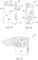
- FIG. 1A depicts an exemplary blank 100.
- the blank 100 includes a plurality of adjoined panels.
- each of the various panels and the blank generally has a first dimension, for example, a length, extending in a first direction, for example, a longitudinal direction, D1, and a second dimension, for example, a width, extending in a second direction, for example, a transverse direction, D2. It will be understood that such designations are made only for convenience and do not necessarily refer to or limit the manner in which the blank is manufactured or erected into a construct.
- the blank 100 includes a plurality of adjoined panels including a main panel 102, a first major panel 104a, a second major panel 104b, a first minor panel 106, and a second minor panel 108.
- the first minor panel 106 is joined to first major panel 104a along a longitudinal fold line 110.
- the main panel 102 is joined to the first minor panel 106 along a longitudinal fold line 112.
- the second minor panel 108 is joined to the main panel 102 along a longitudinal fold line 114.
- the second major panel 104b is joined to the second minor panel 108 along a longitudinal fold line 116.
- Fold lines 110, 112, 116 are substantially parallel and substantially equal in length, as indicated by L1.
- Fold line 114 is substantially parallel to fold lines 110, 112, and 116, but is somewhat shorter in length, as indicated by L2.
- the blank 100 includes partial end panels 118a, 118b respectively joined to panels 104a, 104b along respective curved fold line segments 120a, 120b.
- Each partial end panel 118a, 118b includes a respective end edge 122, 124 that extends in the second direction, a respective exterior edge 126, 128 that extends in the first direction between the respective fold line segment 120a, 120b and the respective end edge 122, 124, and a respective interior edge 130, 132 that extends obliquely between the respective fold line segment 120a, 120b and the respective end edge 122, 124.
- Edges 130, 132 form respective angles A1, A2 with respect to theoretical extensions of fold lines 110, 116 (shown with dashed lines in FIG.
- partial end panel 118a includes a tab or other locking feature 134 extending from end edge 122.
- the blank 100 also includes an end panel 136 joined to the main panel 102 along a substantially arcuate fold line 138.
- the end panel 136 is somewhat lentiform in shape (i.e., shaped like a biconvex lens), with an outwardly arcuate end edge 140 opposite arcuate fold line 138.
- the end panel 136 is asymmetrical or flared in shape, with a pair of side edges 142, 144 that extend divergently and obliquely from the endpoints of fold line 138 to the endpoints of end edge 140. Edges 142, 144 form respective angles A3, A4 with respect to theoretical extensions of fold lines 112, 114 (shown with dashed lines in FIG.
- the end panel 136 includes a somewhat T-shaped slit 146 substantially centered between side edges 142, 144.
- the slit 146 is generally configured to receive the locking feature 134.
- the first minor panel 106 and the second minor panel 108 include respective longitudinal fold lines 148, 150.
- Fold line 148 divides minor panel 106 into two sections or segments, each having a length L1.
- Fold line 150 divides minor panel 108 into two sections or segments having differing lengths, L1 and L2, thereby defining a cutout 152.
- the length of minor panel 106 is approximately equal to the length of the portion of minor panel 108 that lies between fold line 150 and fold line 116.
- longitudinal fold lines 148, 150 are slightly offset from the longitudinal centerline of respective panels 106, 108. Specifically, fold line 148 is slightly closer to fold line 112 and fold line 150 is slightly closer to fold line 114.
- fold lines 148, 150 are slightly closer to fold line 112 and fold line 150 is slightly closer to fold line 114.
- the endpoints of edge 140 do not extend beyond fold lines 110 and 116 (best seen in FIGS. 1D and IE).
- tab 162 does not extend beyond fold line 116. This allows for more efficient cutting of the blank 100 and more efficient packaging and shipping of the construct 174. It will be understood that the precise positioning of fold lines 148 and 150 will vary depending on the shape of end panel 136, the length of edges 142, 144, 140, and angles A3, A4.
- first minor panel 106 and the second minor panel 108 optionally include one or more respective apertures 154, 156.
- aperture 154 is substantially circular in shape and is substantially centered between fold lines 110, 112.
- aperture 156 is substantially circular in shape and is substantially centered between longitudinal fold lines 114, 116.
- the number, shape, size, and positioning of such apertures may vary for a particular application depending on type of construct being formed from the blank, the food item to be heated therein or thereon, the desired degree of browning and/or crisping, whether direct exposure to microwave energy is needed or desired to attain uniform heating of the food item, the need for regulating the change in temperature of the food item through direct heating, and whether and to what extent there is a need for venting.
- the blank 100 includes a removable portion 158 defined at least partially by a tear line or other line of disruption 160 extending in the transverse direction across at least a portion of panels 102, 104a, 104b, 106, 108.
- the removable portion 158 includes an extension or tab 162 extending from the main panel 102 adjacent to peripheral edge 164 of the blank 100.
- An oblique tear line 166 extends from the tab 162 towards, and may abut, tear line 160.
- the tab 162 is somewhat rounded in shape.
- the tab or extension may have any shape as needed or desired.
- the extension may be oval, rectangular, square, diamond-shaped, trapezoidal, polygonal, or any other regular or irregular shape.
- the tear lines 160, 166, cutout 152, and tab 162 may be omitted.
- a microwave energy interactive element 168 overlies at least a portion of blank 100, as shown schematically by stippling in FIG. 1B .
- the microwave energy interactive element may define at least a portion of the interior surface of a construct 174, 182 formed from the blank 100, as shown schematically by stippling in FIGS. 1C-1H .
- the microwave energy interactive element comprises a susceptor.
- other microwave energy interactive elements such as those described below, are contemplated for use with the invention.
- FIGS. 1C-1E numerous sequences of steps may be used to form a sleeve or other construct according to the invention.
- the blank 100 may be folded along longitudinal fold lines 110, 112, 114, 116 and edges 170, 172 brought towards each other to form a sleeve 174 having two open ends 176, 178 with a cavity or interior space 180 therebetween.
- FIG. 1C the blank 100 may be folded along longitudinal fold lines 110, 112, 114, 116 and edges 170, 172 brought towards each other to form a sleeve 174 having two open ends 176, 178 with a cavity or interior space 180 therebetween.
- the first and second major panels 104a, 104b may be overlapped as needed to form a second main panel 104
- partial end panels 118a, 118b may be overlapped as needed to form end panel 118
- fold line segments 120a, 120b may be overlapped as needed to form fold line 120.
- the overlapped panels may be joined to one another using an adhesive or other suitable material or technique.
- the panels 118, 136 are in a substantially opposed, facing relationship with the opposed side edges 142, 144 of end panel 136 extending divergently from the first main panel 102 and opposed side edges 130, 132 of end panel 118 extending convergently from the second main panel 104.
- the first major panel 104a may be dimensioned so that no additional major panel (e.g., the second major panel 104b) is needed to form the second main panel 104.
- the major panel 104a may be folded over and glued to the respective minor panel using a glue flap or otherwise, such that the major panel 104a would serve as the second main panel 104.
- numerous other blanks may be used to form a construct according to the invention.
- the disclosure is not limited to blanks with the left-to-right arrangement of panels illustrated in the figures. Instead, a blank may have "leftmost" and "rightmost" panel (as viewed, for example, in the figures) comprising a main panel, a major panel, a minor panel, a glue flap, or any combination thereof.
- the first minor panel 106 and second minor panel 108 form opposed side walls for the construct 174 , which may be flattened partially ( FIG. 1C ) or substantially ( FIGS. 1D and 1E ) by folding inwardly along fold lines 148, 150.
- the sleeve 174 includes a removable portion 158 comprising the removable portion 158 of the blank 100.
- a food item (not shown) may be inserted through an open end 176 or 178, and the construct with the food item inside may be placed into a microwave oven (not shown). As the food item is heated, the susceptor 168 converts microwave energy to thermal energy, which generally enhances the browning and/or crisping of the surface of the food item.
- any of the panels may include one or more fold lines, score lines, cut lines, cut crease lines, or other lines of disruption along all or a portion of the length or width thereof to accommodate the contours of the particular food item heated therein and to bring the susceptor 168 into closer proximity with the surface of the food item. Any steam generated during heating may be released through the open ends 176, 178 of the sleeve 174 and/or through apertures 154, 156.
- the user may remove the food item and discard the construct 174.
- the user may fold end panels 118 and 136 towards the interior 180 of the sleeve 174 to form a container or construct 182 having an open end 176 and a closed end 178, as shown in FIGS. IF and 1G.
- the closed end 178 may be formed at other times.
- the container 182 may be used to support the food item in an upright configuration with the food item resting on the overlapped panels 118, 136, which collectively serve as a base for the container 182. This provides a convenient means for comfortably handling the heated food item.
- Tab 134 may be inserted into slit 146 to secure the end panels 118, 136 in a locked configuration.
- the closed end or base 178 of the container 182 is somewhat enlarged or widened relative to the open end 176, causing the sides 102, 104 (comprising panels 102a, 102b, 104 of blank 100) to bulge somewhat outwardly from the interior space 180.
- the construct 182 may be able to accommodate various irregular shaped food items, for example, croissant sandwiches, baguettes, calzones, or any other item.
- the container 182 may be more stable when seated in an upright configuration on a surface. Such a shape also might be easier to grasp for some users.
- the construct 182 may begin to interfere with accessing the food item. If desired, the user may insert a finger or other implement into cutout 152, grasp tab 162, and begin to separate the removable portion 158 from the remainder of the construct 182 along tear lines 160, 166, as shown in FIG. 1H . Further pulling results in complete separation of the removable portion 158 from the construct 182, thereby allowing greater access to the food item therein.
- the exemplary blank 100 of FIGS. 1A and 1B and the exemplary constructs 174, 182 of FIGS. 1C-1H include only one removable portion 158, any number and configuration of removable portions may be used in accordance with the invention. Additionally, it will be understood that any type of tear line or other line of disruption may be used to define the removable portion.
- the line of disruption may include a score line, a cut line, a perforated line, kiss cut line, zigzag cut line, zipper cut line, any other suitable line of disruption, or any combination thereof.
- FIGS. 2-7 illustrate examples of blanks including other arrangements of tear lines, cutouts, and other features that define removable portions. Such arrangements of tear lines may be used with other blanks, as illustrated in U.S. Patent Application Publication No. US 2007/0131742A1 , U.S. Patent Application Publication No. US 2007/0131743A1 , U.S. Patent Application Publication No. US 2007/0131744A1 , U.S. Patent Application Publication No. US 2007/0131745A1 , U.S. Patent Application Publication No. US 2007/0138247A1 , and PCT Publication No. WO/2007/067705 .
- the various blanks 200, 300, 400, 500, 600, 700 include features that are similar to blank 100 shown in FIGS. 1A and 1B , except for variations noted and variations that will be understood by those of skill in the art.
- the reference numerals of similar features are preceded in the figures with a "2" ( FIG. 2 ), “3” ( FIG. 3 ), “4" ( FIG. 4 ), “5" ( FIG. 5 ), “6” ( FIG. 6 ), “7” ( FIG. 7 ), instead of a "1".
- Such blanks may be used to form sleeves, containers, and other constructs according to the invention, as described in connection with FIGS. 1A- 1H.
- the blank 200 is similar to the blank 100 of FIG. 1 . except that cutout 252 extends substantially between tab 262 and fold line 216.
- minor panel 208 has an overall length L3 that is less than the length L4 of minor panel 206.
- fold line 250 has a length L3 that is less than the length L4 of fold line 248.
- the larger cutout 252 may facilitate separation of the removable portion 258 along tear lines 260, 266.
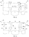
- FIG. 3 schematically depicts another blank 300.
- the blank 300 includes a removable portion 358 at least partially defined by a transverse line of disruption or tear line 360 extending across at least a portion of each of panels 302, 304a, 304b, 306, 308.
- the removable portion 358 includes an extension or tab 362 that partially defines edge 372.
- the tab 362 is somewhat arcuate in shape.
- Tear lines 366a, 366b extend from tab 362 and terminate proximate edge 364 and transverse tear line 360, respectively. Tear lines 366a, 366b cooperate with tab 362 to facilitate removal of the removable portion 358.
- the tab and tear lines may have any suitable shape and configuration.
- the removable portion 358 also includes a cutout 384 that partially defines edge 370.
- cutout 384 is somewhat arcuate in shape.
- the cutout may have any suitable shape as needed or desired, which may or may not correspond to the shape or dimensions of the tab.
- the removable portion 358 also includes a gluing area 386 adjacent the cutout 384. In the blank 300 shown in FIG. 3 , the gluing area 386 is shaped somewhat like an arch or bridge. However, it will be understood that the gluing area may have any suitable shape as needed or desired.
- FIG. 4 schematically depicts another blank 400.
- the blank 400 includes a first removable portion 458a and a second removable portion 458b, each extending in the transverse direction.
- Each removable portion 458a, 458b includes at least a portion of each of panels 402, 404a, 404b, 406, 408.
- the first removable portion 458a is joined to the second removable portion 458b along a transverse tear line 460a.
- the second removable portion 458b is joined to the remainder of panels 402, 404a, 404b, 406, 408 along a transverse tear line 460b.
- the first and second removable portions 458a, 458b each include respective extensions or tabs 462a, 462b that partially define a peripheral edge 472 extending in the longitudinal direction.
- tabs 462a, 462b are substantially arcuate in shape.
- the extension may have any shape as needed or desired, such as those described above.
- Tear lines 466a, 466b extend from and may cooperate with tab 462a to facilitate removal of removable portion 458a.
- tear lines 466c, 466d extend from and may cooperate with tab 462b to facilitate removal of removable portion 458b.
- the first and second removable portions 458a, 458b each include a respective cutout 484a, 484b that partially define peripheral edge 470 extending in the longitudinal direction.
- cutouts 484a, 484b are substantially semi-circular or arcuate in shape.
- cutouts 484a, 484b may have any suitable shape as needed or desired, and may or may not correspond to the shape or dimensions of tabs 462a , 462b.
- the removable portions 458a , 458b also include respective gluing areas 486a, 486b adjacent to cutouts 484a, 484b.
- gluing areas 486a, 486b are shaped somewhat like an arch or bridge. However, the gluing areas may have any suitable shape as needed or desired.
- FIG. 5 schematically depicts another blank 500.
- the blank 500 includes a removable portion 558 defined at least partially by a transverse tear line 560 extending across a portion of each of panels 502, 504a, 504b, 506, 508.
- the removable portion 558 includes a somewhat triangular tab 562 extending from the main panel 502.
- tab 562 comprises at least a portion of minor panel 508 and is defined by a somewhat arcuate or V-shaped cut line 588.
- Tear lines 566a, 566b extend from cut line 588 towards, and may abut, edge 564 and transverse tear line 560, respectively, and may cooperate with tab 562 to facilitate removal of the removable portion 558.
- FIG. 6 schematically depicts another blank 600.
- the blank 600 includes a removable portion 658 defined at least partially by a transverse tear line 660 extending across at least a portion of panels 602, 604a, 604b, 606, 608.
- the removable portion 658 includes a somewhat elongate cutout 652 in the first main panel 602 and the second minor panel 608 terminating proximate to fold line 650.
- the portion of cutout 652 in the first main panel 602 is somewhat semi-circular in shape with an arcuate grasping edge 688.
- the portion of the cutout 652 in the second minor panel 608 is generally rectangular or square in shape.
- Tear lines 666a, 666b extend from edge 688 towards, and may abut, edge 664 and transverse tear line 660, respectively, and cooperate with grasping edge 688 to facilitate removal of the removable portion 658.
- FIG. 7 schematically depicts another blank 700.
- the blank of FIG. 7 is similar to the blank of FIG. 6 , except that cutout 752 lies within the second minor panel 708 and extends substantially between fold lines 714 and 750.
- the cutout 752 is somewhat square or rectangular in shape with a substantially straight grasping edge 788 substantially aligned with fold line 714.
- Numerous materials may be suitable for use in forming the various blanks and constructs of the invention, provided that the materials are resistant to softening, scorching, combusting, or degrading at typical microwave oven heating temperatures, for example, at from about 121°C to about 218°C (250°F to about 425°F).
- the particular materials used may include microwave energy interactive materials and microwave energy transparent or inactive materials.
- any of the various blanks or constructs of the present invention may include one or more features that alter the effect of microwave energy during the heating or cooking of the food item.
- the blank or construct may be formed at least partially from one or more microwave energy interactive elements (hereinafter sometimes referred to as "microwave interactive elements") that promote browning and/or crisping of a particular area of the food item, shield a particular area of the food item from microwave energy to prevent overcooking thereof, or transmit microwave energy toward or away from a particular area of the food item.
- microwave interactive elements comprises one or more microwave energy interactive materials or segments arranged in a particular configuration to absorb microwave energy, transmit microwave energy, reflect microwave energy, or direct microwave energy, as needed or desired for a particular microwave heating construct and food item.
- the microwave interactive element may be supported on a microwave inactive or transparent substrate for ease of handling and/or to prevent contact between the microwave energy interactive material and the food item.
- a microwave interactive element supported on a microwave transparent substrate includes both microwave interactive and microwave inactive elements or components, such constructs are referred to herein as "microwave interactive webs".
- the microwave energy interactive material may be an electroconductive or semiconductive material, for example, a metal or a metal alloy provided as a metal foil; a vacuum deposited metal or metal alloy; or a metallic ink, an organic ink, an inorganic ink, a metallic paste, an organic paste, an inorganic paste, or any combination thereof.
- metals and metal alloys that may be suitable for use with the present invention include, but are not limited to, aluminum, chromium, copper, inconel alloys (nickel-chromium-molybdenum alloy with niobium), iron, magnesium, nickel, stainless steel, tin, titanium, tungsten, and any combination or alloy thereof.
- the microwave energy interactive material may comprise a metal oxide.
- metal oxides that may be suitable for use with the present invention include, but are not limited to, oxides of aluminum, iron, and tin, used in conjunction with an electrically conductive material where needed.
- ITO indium tin oxide
- ITO can be used as a microwave energy interactive material to provide a heating effect, a shielding effect, a browning and/or crisping effect, or a combination thereof.
- ITO may be sputtered onto a clear polymer film. The sputtering process typically occurs at a lower temperature than the evaporative deposition process used for metal deposition.
- ITO has a more uniform crystal structure and, therefore, is clear at most coating thicknesses. Additionally, ITO can be used for either heating or field management effects. ITO also may have fewer defects than metals, thereby making thick coatings of ITO more suitable for field management than thick coatings of metals, such as aluminum.
- the microwave energy interactive material may comprise a suitable electroconductive, semiconductive, or non-conductive artificial dielectric or ferroelectric.
- Artificial dielectrics comprise conductive, subdivided material in a polymeric or other suitable matrix or binder, and may include flakes of an electroconductive metal, for example, aluminum.
- the microwave interactive element may comprise a thin layer of microwave interactive material (generally less than about 10 nm (100 angstroms) in thickness, for example, from about 6 to about 10 nm (60 to about 100 angstroms) in thickness) that tends to absorb at least a portion of impinging microwave energy and convert it to thermal energy (i.e., heat) at the interface with a food item.
- microwave interactive material generally less than about 10 nm (100 angstroms) in thickness, for example, from about 6 to about 10 nm (60 to about 100 angstroms) in thickness
- thermal energy i.e., heat
- a susceptor may overlie all or a portion of one or more of the panels, as illustrated schematically in FIG. 1B , and may form at least a portion of the surface proximate the food item, as illustrated schematically in FIGS. 1C-1H .
- FIGS. 1C-1H illustrates that other microwave energy interactive elements, such as those described herein, are contemplated for use with the invention.
- the microwave interactive element may comprise a foil having a thickness sufficient to shield one or more selected portions of the food item from microwave energy (sometimes referred to as a "shielding element").
- shielding elements may be used where the food item is prone to scorching or drying out during heating.
- the shielding element may be formed from various materials and may have various configurations, depending on the particular application for which the shielding element is used.
- the shielding element is formed from a conductive, reflective metal or metal alloy, for example, aluminum, copper, or stainless steel.
- the shielding element generally may have a thickness of from about 0.00724 mm to about 1.27 mm (0.000285 inches to about 0.05 inches).
- the shielding element has a thickness of from about 0.00762 mm to about 0.762 mm (0.0003 inches to about 0.03 inches). In another aspect, the shielding element has a thickness of from about 0.00889 mm to about 0.508 mm (0.00035 inches to about 0.020 inches), for example, 0.406 mm (0.016 inches).
- the microwave interactive element may comprise a segmented foil, such as, but not limited to, those described in U.S. Patent Nos. 6,204,492 , 6,433,322 , 6,552,315 , and 6,677,563 .
- segmented foils are not continuous, appropriately spaced groupings of such segments may act as a transmitting element to direct microwave energy to specific areas of the food item.
- Such foils also may be used in combination with browning and/or crisping elements, for example, susceptors.
- any of the numerous microwave interactive elements described herein or contemplated hereby may be substantially continuous, that is, without substantial breaks or interruptions, or may be discontinuous, for example, by including one or more breaks or apertures that transmit microwave energy therethrough.
- the breaks or apertures may be sized and/or positioned to heat particular areas of the food item selectively.
- the number, shape, size, and positioning of such breaks or apertures may vary for a particular application depending on type of construct being formed, the food item to be heated therein or thereon, the desired degree of shielding, browning, and/or crisping, whether direct exposure to microwave energy is needed or desired to attain uniform heating of the food item, the need for regulating the change in temperature of the food item through direct heating, whether and to what extent there is a need for venting, and numerous other factors.
- the aperture may be a physical aperture or void in the material used to form the construct, or may be a non-physical "aperture".
- a non-physical aperture may be a portion of the construct that is microwave energy inactive by deactivation or otherwise, or one that is otherwise transparent to microwave energy.
- the aperture may be a portion of the construct formed without a microwave energy interactive material or, alternatively, may be a portion of the construct formed with a microwave energy interactive material that has been deactivated. While both physical and non-physical apertures allow the food item to be heated directly by the microwave energy, a physical aperture also provides a venting function to allow steam or other vapors to be released from the food item.
- panels 104a and 104b are overlapped to form the second main panel 104.
- the concentration of heat generated by the overlapped panels may be sufficient to cause the underlying support, in this case, paperboard, to become scorched.
- the overlapping portions of one or both of panels 104a and 104b may be designed to be microwave inactive, for example, by forming these areas without a microwave energy interactive material or by deactivating the microwave energy interactive material in these areas.
- one or more panels, portions of panels, or portions of the construct may be designed to be microwave energy inactive to ensure that the microwave energy is focused efficiently on the areas to be browned and/or crisped, rather than being lost to portions of the food item not intended to be browned and/or crisped or to the heating environment.
- any of the above elements and numerous others contemplated hereby may be supported on a substrate.
- the substrate typically comprises an electrical insulator, for example, a polymer film or other polymeric material.
- polymer polymer film or other polymeric material
- polymeric material include, but are not limited to, homopolymers, copolymers, such as for example, block, graft, random, and alternating copolymers, terpolymers, etc. and blends and modifications thereof.
- the term "polymer” shall include all possible geometrical configurations of the molecule. These configurations include, but are not limited to isotactic, syndiotactic, and random symmetries.
- the thickness of the film typically may be from about 8.89 ⁇ m to about 0.254 mm (35 gauge to about 10 mil). In one aspect, the thickness of the film is from about 10.16 to about 20.32 ⁇ m (40 to about 80 gauge). In another aspect, the thickness of the film is from about 11.43 to about 12.7 ⁇ m (45 to about 50 gauge). In still another aspect, the thickness of the film is about 12.19 ⁇ m (48 gauge).
- polymer films that may be suitable include, but are not limited to, polyolefins, polyesters, polyamides, polyimides, polysulfones, polyether ketones, cellophanes, or any combination thereof. Other non-conducting substrate materials such as paper and paper laminates, metal oxides, silicates, cellulosics, or any combination thereof, also may be used.
- the polymer film comprises polyethylene terephthalate (PET).
- PET polyethylene terephthalate
- Polyethylene terephthalate films are used in commercially available susceptors, for example, the QWIKWAVE ® Focus susceptor and the MICRORITE ® susceptor, both available from Graphic Packaging International (Marietta, Georgia).
- Examples of polyethylene terephthalate films that may be suitable for use as the substrate include, but are not limited to, MELINEX ® , commercially available from DuPont Teijan Films (Hopewell, Virginia), SKYROL, commercially available from SKC, Inc. (Covington, Georgia), and BARRIALOX PET, available from Toray Films (Front Royal, VA), and QU50 High Barrier Coated PET, available from Toray Films (Front Royal, VA).
- the polymer film may be selected to impart various properties to the microwave interactive web, for example, printability, heat resistance, or any other property.
- the polymer film may be selected to provide a water barrier, oxygen barrier, or a combination thereof.
- barrier film layers may be formed from a polymer film having barrier properties or from any other barrier layer or coating as desired.
- Suitable polymer films may include, but are not limited to, ethylene vinyl alcohol, barrier nylon, polyvinylidene chloride, barrier fluoropolymer, nylon 6, nylon 6,6, coextruded nylon 6/EVOH/nylon 6, silicon oxide coated film, harrier polyethylene terephthalate, or any combination thereof.
- Another example of a barrier film that may be suitable is CAPRAN® OXYSHIELD OBS monoaxially oriented coextruded nylon 6/ethylene vinyl alcohol (EVOH)/nylon 6, also commercially available from Honeywell International.
- Yet another example of a barrier film that may be suitable for use with the present invention is DARTEK® N-201 nylon 6,6, commercially available from Enhance Packaging Technologies (Webster, New York). Additional examples include BARRIALOX PET, available from Toray Films (Front Royal, VA) and QU50 High Barrier Coated PET, available from Toray Films (Front Royal, VA), referred to above.
- a susceptor may have a structure including a film, for example, polyethylene terephthalate, with a layer of silicon oxide coated onto the film, and ITO or other material deposited over the silicon oxide. If needed or desired, additional layers or coatings may be provided to shield the individual layers from damage during processing.
- the barrier film may have an oxygen transmission rate (OTR) as measured using ASTM D3985 of less than about 20 cc/m 2 /day.
- OTR oxygen transmission rate
- the barrier film has an OTR of less than about 10 cc/m 2 /day.
- the barrier film has an OTR of less than about 1 cc/m 2 /day.
- the barrier film has an OTR of less than about 0.5 cc/m 2 /day.
- the barrier film has an OTR of less than about 0.1 cc/m 2 /day.
- the barrier film may have a water vapor transmission rate (WVTR) of less than about 100 g/m 2 /day as measured using ASTM F1249. In one aspect, the barrier film has a water vapor transmission rate of less than about 50 g/m 2 /day. In another aspect, the barrier film has a WVTR of less than about 15 g/m 2 /day. In yet another aspect, the barrier film has a WVTR of less than about 1 g/m 2 /day. In still another aspect, the barrier film has a WVTR of less than about 0.1 g/m 2 /day. In a still further aspect, the barrier film has a WVTR of less than about 0.05 g/m 2 /day.
- WVTR water vapor transmission rate
- non-conducting substrate materials such as metal oxides, silicates, cellulosics, or any combination thereof, also may be used in accordance with the present invention.
- the microwave energy interactive material may be applied to the substrate in any suitable manner, and in some instances, the microwave energy interactive material is printed on, extruded onto, sputtered onto, evaporated on, or laminated to the substrate.
- the microwave energy interactive material may be applied to the substrate in any pattern, and using any technique, to achieve the desired heating effect of the food item.
- the microwave energy interactive material may be provided as a continuous or discontinuous layer or coating including circles, loops, hexagons, islands, squares, rectangles, octagons, and so forth. Examples of various patterns and methods that may be suitable for use with the present invention are provided in U.S. Patent Nos.
- microwave interactive element or microwave interactive web may be joined to or overlie a dimensionally stable, microwave energy transparent support (also referred to as "microwave transparent support”, “microwave inactive support” or “support”) to form at least a portion of the construct.
- microwave transparent support also referred to as "microwave transparent support”, “microwave inactive support” or “support”
- all or a portion of the support may be formed at least partially from a paperboard material, which may be cut into a blank prior to use in the construct.
- the support may be formed from paperboard having a basis weight of from about 97.65 g/m 2 to about 537.08 g/m 2 (60 to about 330 lbs/ream), for example, from about 130.2 g/m 2 to about 227.85 g/m 2 (80 to about 140 lbs/ream).
- the paperboard generally may have a thickness of from about 0.1524 mm to about 0.762 mm (6 to about 30 mils), for example, from about 0.3048 mm to about 0.711 mm (12 to about 28 mils). In one particular example, the paperboard has a thickness of about 0.3048 mm (12 mils). Any suitable paperboard may be used, for example, a solid bleached or solid unbleached sulfate board, such as SUS® board, commercially available from Graphic Packaging International.
- the support may comprise a paper or paper-based material generally having a basis weight of from about 24.41 g/m 2 to about 97.65 g/m 2 (15 to about 60 lbs/ream), for example, from about 32.55 g/m 2 to about 65.1 g/m 2 (20 to about 40 lbs/ream).
- the paper has a basis weight of about 40.69 g/m 2 (25 lbs/ream).
- one or more portions or sides of the various blanks or other constructs described herein or contemplated hereby may be coated with varnish, clay, or other materials, either alone or in combination.
- at least the side of the support that will form an exterior surface of a construct erected therefrom may be coated with a clay coating or other base coating.
- the coating may then be printed over with product advertising, images, price coding, any other information or indicia, or any combination thereof.
- the blank or construct may then be overcoated with a varnish to protect any information printed thereon.
- the blanks or other constructs may be coated with, for example, a moisture and/or oxygen barrier layer, on either or both sides, such as those described above.
- a moisture and/or oxygen barrier layer on either or both sides, such as those described above.
- Any suitable moisture and/or oxygen barrier material may be used in accordance with the present invention. Examples of materials that may be suitable include, but are not limited to, polyvinylidene chloride, ethylene vinyl alcohol, DuPont DARTEKTM nylon 6,6, and others referred to above.
- any of the blanks or other constructs of the present invention may be coated or laminated with other materials to impart other properties, such as absorbency, repellency, opacity, color, printability, stiffness, or cushioning.
- absorbent susceptors are described in U.S. Provisional Application No. 60/604,637, filed August 25, 2004 , and U.S. Patent Application Publication No. US 2006/0049190 A1, published March 9, 2006 .
- the blanks or other constructs may include graphics or indicia printed thereon.
- the microwave interactive element may have a grey or silver color that is visually distinguishable from the substrate or the support.
- the present invention contemplates using a silver or grey toned adhesive to join the microwave interactive elements to the substrate, using a silver or grey toned substrate to mask the presence of the silver or grey toned microwave interactive element, using a dark toned substrate, for example, a black toned substrate, to conceal the presence of the silver or grey toned microwave interactive element, overprinting the metallized side of the web with a silver or grey toned ink to obscure the color variation, printing the non-metallized side of the web with a silver or grey ink or other concealing color in a suitable pattern or as a solid color layer to mask or conceal the presence of the microwave interactive element, or any other suitable technique or combination thereof.
- the construct is somewhat rectangular in shape, suitable, for example, for heating a sandwich or breakfast pastry therein.
- numerous suitable shapes and configurations may be used to form the various panels and, therefore, constructs. Examples of other shapes encompassed hereby include, but are not limited to, polygons, circles, ovals, cylinders, prisms, spheres, polyhedrons, and ellipsoids.
- the shape of each panel may be determined largely by the shape of the food item, and it should be understood that different packages are contemplated for different food items, for example, sandwiches, pizzas, French fries, soft pretzels, pizza bites, cheese sticks, pastries, doughs, and so forth.
- the construct may be flexible, semi-rigid, rigid, or may include a variety of components having different degrees of flexibility. Likewise, the construct may include gussets, pleats, or any other feature needed or desired to accommodate a particular food item and/or portion size. Additionally, it will be understood that the present invention contemplates blanks and constructs for single-serving portions and for multiple-serving portions.
- a fold line can be any substantially linear, although not necessarily straight, form of weakening that facilitates folding therealong. More specifically, but not for the purpose of narrowing the scope of the present invention, a fold line may be a score line, such as lines formed with a blunt scoring knife, or the like, which creates a crushed portion in the material along the desired line of weakness, a cut that extends partially into a material along the desired line of weakness, and/or a series of cuts that extend partially into and/or completely through the material along the desired line of weakness; or any combination of these features.
- one type of conventional tear line is in the form of a series of cuts that extend completely through the material, with adjacent cuts being spaced apart slightly so that a nick (e.g., a small somewhat bridging-like piece of the material) is defined between the adjacent cuts for typically temporarily connecting the material across the tear line.
- the nicks are broken during tearing along the tear line.
- Such a tear line that includes nicks can also be referred to as a cut line, since the nicks typically are a relatively small percentage of the subject line, and alternatively the nicks can be omitted from such a cut line.
- various exemplary blanks and constructs are shown and described herein as having fold lines, tear lines, score lines, cut lines, kiss cut lines, and other lines as extending from a particular feature to another particular feature, for example from one particular panel to another, from one particular edge to another, or any combination thereof.
- such lines need not necessarily extend between such features in a precise manner. Instead, such lines may generally extend between the various features as needed to achieve the objective of such line. For instance, where a particular tear line is shown as extending from a first edge of a blank to another edge of the blank, the tear line need not extend completely to one or both of such edges. Rather, the tear line need only extend to a location sufficiently proximate to the edge so that the removable strip, panel, or portion can be manually separated from the blank or construct without causing undesirable damage thereto.
Landscapes
- Engineering & Computer Science (AREA)
- Mechanical Engineering (AREA)
- Life Sciences & Earth Sciences (AREA)
- Food Science & Technology (AREA)
- Health & Medical Sciences (AREA)
- Nutrition Science (AREA)
- Chemical & Material Sciences (AREA)
- Polymers & Plastics (AREA)
- Cartons (AREA)
- Cookers (AREA)
- Package Specialized In Special Use (AREA)
- Packages (AREA)
Claims (14)
- Mikrowellenerwärmungskonstrukt (174), umfassend:ein erstes Hauptfeld (102; 202; 602) und ein zweites Hauptfeld (104), die einander gegenüberliegen;ein erstes Nebenfeld (106; 206; 606) und ein zweites Nebenfeld (108; 208; 608; 708), die einander gegenüberliegen, wobei das erste Nebenfeld und das zweite Nebenfeld faltbar mit dem ersten Hauptfeld und dem zweiten Hauptfeld entlang jeweiliger Faltlinien (110, 112, 114, 116) verbunden sind, um wenigstens teilweise einen Innenraum (180) zu definieren, wobei ein Mikrowellenenergie interaktives Material (168) über wenigstens einem Abschnitt von wenigstens einem aus dem ersten Hauptfeld (102; 202; 602), dem zweiten Hauptfeld (104), dem ersten Nebenfeld (106; 206; 606) und dem zweiten Nebenfeld (108; 208; 608; 708) auf einer dem Innenraum zugewandten Seite des jeweiligen Felds liegt;wobei das erste Hauptfeld und das zweite Hauptfeld jeweils eine Breite aufweisen, die sich zwischen einem jeweiligen Paar der Faltlinien (110, 112, 114, 116) erstreckt undwobei ein erstes Endfeld (136) faltbar mit dem ersten Hauptfeld entlang einer bogenförmigen Faltlinie (138) verbunden ist, wobei die bogenförmige Faltlinie ein Paar von Endpunkten aufweist, die entlang der Faltlinien (112, 114) des ersten Hauptfelds positioniert sind, wobei das erste Endfeld ein Paar gegenüberliegender Seitenkanten (142, 144) umfasst, die sich von den Endpunkten der bogenförmigen Faltlinie zu Endpunkten einer bogenförmigen Endkante (140) gegenüber der bogenförmigen Faltlinie erstrecken;wobei das Konstrukt einen entfernbaren Abschnitt (158; 258; 658) umfasst, der wenigstens einen Abschnitt von wenigstens einem aus dem ersten Hauptfeld, dem zweiten Hauptfeld, dem ersten Nebenfeld und dem zweiten Nebenfeld umfasst, wobei der entfernbare Abschnitt wenigstens teilweise definiert ist durcheine querverlaufende Reißlinie (160; 260; 660), die sich wenigstens teilweise über das jeweilige Feld erstreckt,eine schräge Reißlinie (166; 266; 666b), die im Wesentlichen an der querverlaufenden Reißlinie anstößt, undeinen Ausschnitt (152; 252; 652; 752) in der Nähe der schrägen Reißlinie,dadurch gekennzeichnet, dassdas erste und das zweite Nebenfeld (106, 108) jeweilige Längsfaltlinien (148, 150) umfassen, die geringfügig gegenüber der Längsmittellinie der jeweiligen Felder (106, 108) versetzt sind und die jeweils geringfügig näher an der Faltlinie (112) liegen, die das erste Hauptfeld mit dem ersten Nebenfeld verbindet, und die geringfügig näher an der Faltlinie (114) liegen, die das erste Hauptfeld mit dem zweiten Nebenfeld verbindet,wobei die Breite des zweiten Hauptfelds (104) größer ist als die Breite des ersten Hauptfelds (102; 202; 602), wenn das Konstrukt aus einem Zuschnitt ausgebildet wird, und im Wesentlichen entlang der Längsfaltlinien (148, 150) des ersten und zweiten Nebenfelds (106, 108) abgeflacht ist,wobei die gegenüberliegenden Seitenkanten (142, 144) des ersten Endfelds sich divergent von den Endpunkten der bogenförmigen Faltlinie (138) zu den Endpunkten der bogenförmigen Endkante (140) erstrecken.
- Konstrukt nach Anspruch 1, des Weiteren umfassend
ein zweites Endfeld (118), das faltbar mit dem zweiten Hauptfeld verbunden ist, wobei das zweite Endfeld ein Paar gegenüberliegende Seitenkanten (130, 132) aufweist, die sich konvergent vom zweiten Hauptfeld aus erstrecken. - Konstrukt nach Anspruch 2, wobei das zweite Endfeld (118) mit dem zweiten Hauptfeld (104) entlang einer bogenförmigen Faltlinie (120) faltbar verbunden ist.
- Konstrukt nach Anspruch 2 oder 3, wobei
in einer ersten Konfiguration sich das erste Endfeld (136) und das zweite Endfeld (118) in einer im Wesentlichen gegenüberliegenden zugewandten Beziehung befinden und
in einer zweiten Konfiguration das erste Endfeld und das zweite Endfeld in Richtung des Innenraums gefaltet und übereinander gelegt sind. - Konstrukt nach einem der Ansprüche 2 bis 4, wobei das zweite Endfeld (118) eine im Wesentlichen lineare Endkante (122, 124) aufweist, die sich zwischen dem Paar von Seitenkanten (130; 132) des zweiten Endfelds erstreckt.
- Konstrukt nach Anspruch 5, wobei
ein Verriegelungsmerkmal (134) sich von der im Wesentlichen linearen Endkante des zweiten Endfelds (118) aus erstreckt und
das Verriegelungsmerkmal ausgelegt ist, um in einem Schlitz (146) im ersten Endfeld (136) aufgenommen zu werden. - Konstrukt nach einem der Ansprüche 1 bis 6, wobei sich der Ausschnitt (152; 252; 652; 752) von einem Ende des Konstrukts nach innen erstreckt.
- Konstrukt nach Anspruch 7, wobei der Ausschnitt (152; 252; 652; 752) wenigstens teilweise eine Lasche (162, 262) definiert.
- Konstrukt nach Anspruch 8, wobei sich die schräge Reißlinie (166; 266; 666b) im Wesentlichen zwischen der Lasche (162; 262) und der querverlaufenden Reißlinie (160; 260; 660) erstreckt.
- Konstrukt nach einem der Ansprüche 1 bis 6, wobei der Ausschnitt (152; 252; 652; 752) in wenigstens einem aus dem ersten Hauptfeld (102; 202; 602), dem zweiten Hauptfeld (104), dem ersten Nebenfeld (106; 206; 606) und dem zweiten Nebenfeld (108; 208; 608; 708) entfernt von einem Ende des Konstrukts angeordnet ist.
- Konstrukt nach Anspruch 10, wobei
der Ausschnitt (152; 252; 652; 752) im zweiten Nebenfeld (108; 208; 608; 708) angeordnet ist und
der Ausschnitt sich im Wesentlichen zwischen dem ersten Hauptfeld und dem zweiten Hauptfeld (104) erstreckt. - Konstrukt des Anspruchs 10, wobei
der Ausschnitt (152; 252; 652; 752) im zweiten Nebenfeld (108; 208; 608; 708) angeordnet ist und
der Ausschnitt sich teilweise zwischen dem ersten Hauptfeld (102; 202; 602) und dem zweiten Hauptfeld (104) erstreckt. - Konstrukt nach Anspruch 11 oder 12, wobei der Ausschnitt (152; 252; 652; 752) des Weiteren im ersten Hauptfeld (102; 202; 602) angeordnet ist.
- Konstrukt nach einem der Ansprüche 1 bis 13, wobei das Mikrowellenenergie interaktive Material (168) zum Umwandeln wenigstens eines Teils der auftreffenden Mikrowellenenergie in Wärmeenergie wirksam ist.
Applications Claiming Priority (2)
| Application Number | Priority Date | Filing Date | Title |
|---|---|---|---|
| US96465507P | 2007-08-13 | 2007-08-13 | |
| EP08727453.6A EP2176139B1 (de) | 2007-08-13 | 2008-01-09 | Zuschnitt zur herstellung einer struktur zur mikrowellenbeheizung |
Related Parent Applications (2)
| Application Number | Title | Priority Date | Filing Date |
|---|---|---|---|
| EP08727453.6A Division EP2176139B1 (de) | 2007-08-13 | 2008-01-09 | Zuschnitt zur herstellung einer struktur zur mikrowellenbeheizung |
| EP08727453.6A Division-Into EP2176139B1 (de) | 2007-08-13 | 2008-01-09 | Zuschnitt zur herstellung einer struktur zur mikrowellenbeheizung |
Publications (2)
| Publication Number | Publication Date |
|---|---|
| EP2500293A1 EP2500293A1 (de) | 2012-09-19 |
| EP2500293B1 true EP2500293B1 (de) | 2017-08-23 |
Family
ID=39361281
Family Applications (3)
| Application Number | Title | Priority Date | Filing Date |
|---|---|---|---|
| EP12004441.7A Active EP2500293B1 (de) | 2007-08-13 | 2008-01-09 | Mikrowellenerhitzungskonstruktion |
| EP08727453.6A Active EP2176139B1 (de) | 2007-08-13 | 2008-01-09 | Zuschnitt zur herstellung einer struktur zur mikrowellenbeheizung |
| EP10004338.9A Active EP2208689B1 (de) | 2007-08-13 | 2008-01-09 | Behälter, um Lebensmittel in einem Mikrowellenofen zu erwärmen, knusprig werden zu lassen und zu bräunen |
Family Applications After (2)
| Application Number | Title | Priority Date | Filing Date |
|---|---|---|---|
| EP08727453.6A Active EP2176139B1 (de) | 2007-08-13 | 2008-01-09 | Zuschnitt zur herstellung einer struktur zur mikrowellenbeheizung |
| EP10004338.9A Active EP2208689B1 (de) | 2007-08-13 | 2008-01-09 | Behälter, um Lebensmittel in einem Mikrowellenofen zu erwärmen, knusprig werden zu lassen und zu bräunen |
Country Status (5)
| Country | Link |
|---|---|
| US (3) | US8309896B2 (de) |
| EP (3) | EP2500293B1 (de) |
| CA (1) | CA2694535C (de) |
| ES (3) | ES2532859T3 (de) |
| WO (1) | WO2009023286A1 (de) |
Families Citing this family (51)
| Publication number | Priority date | Publication date | Assignee | Title |
|---|---|---|---|---|
| US7667167B2 (en) | 2005-12-08 | 2010-02-23 | Graphic Packaging International, Inc. | Microwave food heating package with removable portion |
| EP2500293B1 (de) | 2007-08-13 | 2017-08-23 | Graphic Packaging International, Inc. | Mikrowellenerhitzungskonstruktion |
| EP2286151B1 (de) * | 2008-06-09 | 2016-05-04 | Graphic Packaging International, Inc. | Interaktive mikrowellenenergiestruktur mit mikroöffnungen |
| CA2757009C (en) * | 2009-04-28 | 2015-08-25 | Graphic Packaging International, Inc. | Vented susceptor structure |
| WO2011091339A2 (en) * | 2010-01-25 | 2011-07-28 | Graphic Packaging International, Inc. | Package for multiple food items |
| WO2011126751A2 (en) * | 2010-03-29 | 2011-10-13 | Graphic Packaging International, Inc. | Microwave heating apparatus with food supporting cradle |
| MX2013012408A (es) * | 2011-04-25 | 2013-12-06 | Graphic Packaging Int Inc | Bolsas interactivas con energia de microondas. |
| US9078296B2 (en) * | 2011-06-08 | 2015-07-07 | Graphic Packaging International, Inc. | Tray with curved bottom surface |
| US20130105471A1 (en) * | 2011-10-27 | 2013-05-02 | Maik Hach | System and apparatus for a flexible moisture absorbent microwave package |
| US9334100B2 (en) | 2012-07-18 | 2016-05-10 | Sfc Global Supply Chain, Inc. | Patterned dual susceptor |
| ITRM20130034U1 (it) | 2013-02-14 | 2014-08-15 | Seda Suisse A G | Contenitore con apertura facilitata |
| EP3024747B1 (de) | 2013-07-25 | 2022-05-04 | Graphic Packaging International, LLC | Karton für lebensmittelprodukt |
| US9771176B2 (en) | 2013-09-25 | 2017-09-26 | Graphic Packaging International, Inc. | Reinforced package |
| US9957080B2 (en) | 2013-09-25 | 2018-05-01 | Graphic Packaging International, Llc | Reinforced package |
| WO2015048242A1 (en) | 2013-09-25 | 2015-04-02 | Graphic Packaging International, Inc. | Reinforced package |
| WO2016064975A1 (en) | 2014-10-21 | 2016-04-28 | Graphic Packaging International, Inc. | Package for a product |
| US10232973B2 (en) | 2014-11-07 | 2019-03-19 | Graphic Packaging International, Llc | Tray for holding a food product |
| US10336500B2 (en) | 2014-11-07 | 2019-07-02 | Graphic Packaging International, Llc | Tray for holding a food product |
| CA2980192C (en) | 2015-04-29 | 2019-05-07 | Graphic Packaging International, Inc. | Method and system for forming packages |
| EP3288834B1 (de) | 2015-04-29 | 2020-02-26 | Graphic Packaging International, LLC | Verfahren und system zur formung von verpackungen |
| CN107848723B (zh) | 2015-07-14 | 2020-09-22 | 印刷包装国际有限责任公司 | 用于形成包装的方法和系统 |
| AU2016313403B2 (en) | 2015-08-21 | 2019-10-10 | Graphic Packaging International, Llc | Reinforced package |
| DE102016120615A1 (de) * | 2016-01-27 | 2017-07-27 | Lidl Stiftung & Co. Kg | Verfahren zum Herstellen, Garen und Präsentieren eines Lebensmittelprodukts sowie Verpackung zur Verwendung in diesem Verfahren |
| US11040798B2 (en) | 2017-08-09 | 2021-06-22 | Graphie Packaging International, LLC | Method and system for forming packages |
| US10661940B2 (en) | 2017-09-06 | 2020-05-26 | Graphic Packaging International, Llc | Carton with at least one holder |
| USD842095S1 (en) | 2017-10-10 | 2019-03-05 | Graphic Packaging International, Llc | Carton |
| DK179991B1 (da) * | 2018-06-04 | 2020-01-14 | Trykkeriet Friheden Aps | Pudeæske |
| WO2020014104A1 (en) | 2018-07-09 | 2020-01-16 | Graphic Packaging International, Llc | Method and system for forming packages |
| NZ771747A (en) | 2018-08-06 | 2023-03-31 | Graphic Packaging Int Llc | Container with at least one compartment |
| US12344445B2 (en) | 2018-11-20 | 2025-07-01 | Graphic Packaging International, Llc | Adjustable tray |
| WO2020159818A1 (en) | 2019-01-28 | 2020-08-06 | Graphic Packaging International, Llc | Reinforced package |
| ES2990243T3 (es) | 2019-02-28 | 2024-11-29 | Graphic Packaging Int Llc | Caja de cartón para un producto alimenticio |
| USD899246S1 (en) | 2019-04-24 | 2020-10-20 | Graphic Packaging International, Llc | Carton |
| WO2021054499A1 (ko) * | 2019-09-19 | 2021-03-25 | 씨제이제일제당 (주) | 냉동식품, 냉동식품 포장 용기 및 냉동식품의 포장재 |
| USD1042113S1 (en) | 2020-01-24 | 2024-09-17 | Graphic Packaging International, Llc | Reinforcing carton |
| USD999055S1 (en) | 2020-10-29 | 2023-09-19 | Graphic Packaging International, Llc | Carton |
| MX2023005267A (es) | 2020-11-06 | 2023-07-26 | Graphic Packaging Int Llc | Bandeja para productos alimenticios. |
| EP4267385A4 (de) | 2020-12-22 | 2024-12-18 | Graphic Packaging International, LLC | Endklappeneingriffsanordnung zum aufrichten von kartons und zugehörige systeme und verfahren |
| USD1042121S1 (en) | 2021-05-27 | 2024-09-17 | Graphic Packaging International, Llc | Tray |
| USD1042119S1 (en) | 2021-05-27 | 2024-09-17 | Graphic Pachaging International, LLC | Tray |
| USD1044494S1 (en) | 2021-05-27 | 2024-10-01 | Graphic Packaging International, Llc | Tray |
| USD1042116S1 (en) | 2021-05-27 | 2024-09-17 | Graphic Packaging International, Llc | Carton |
| USD1062459S1 (en) | 2021-05-27 | 2025-02-18 | Graphic Packaging International, Llc | Tray |
| USD1042117S1 (en) | 2021-05-27 | 2024-09-17 | Graphic Packaging International, Llc | Tray |
| USD1042118S1 (en) | 2021-05-27 | 2024-09-17 | Graphic Packaging International, Llc | Tray |
| USD1042122S1 (en) | 2021-05-27 | 2024-09-17 | Graphic Packaging International, Llc | Tray |
| USD1042120S1 (en) | 2021-05-27 | 2024-09-17 | Graphic Packaging International, Llc | Tray |
| EP4384448A4 (de) | 2021-08-11 | 2025-06-18 | Graphic Packaging International, LLC | Karton für lebensmittel |
| USD1029629S1 (en) | 2022-05-31 | 2024-06-04 | Graphic Packaging International, Llc | Carton |
| DE102022213560A1 (de) * | 2022-12-13 | 2024-06-13 | Robert Bosch Gesellschaft mit beschränkter Haftung | Werkzeugzubehörverpackung und Werkzeugzubehörprodukt |
| USD1091334S1 (en) | 2023-05-11 | 2025-09-02 | Graphic Packaging International, Llc | Tray with divider features |
Family Cites Families (100)
| Publication number | Priority date | Publication date | Assignee | Title |
|---|---|---|---|---|
| US359435A (en) | 1887-03-15 | Paper box | ||
| US1516090A (en) * | 1923-03-28 | 1924-11-18 | Benjamin L Gary | Carton |
| US2132966A (en) * | 1937-03-19 | 1938-10-11 | Edson A O'brien | Contection |
| US3240419A (en) * | 1964-09-15 | 1966-03-15 | American Can Co | Carton with integral tear-strip sealing means |
| US3324998A (en) * | 1965-10-23 | 1967-06-13 | Reynolds Metals Co | Container and blanks for making same |
| US3637130A (en) * | 1970-08-10 | 1972-01-25 | Reynolds Metals Co | Container and blanks for making same |
| US4190757A (en) | 1976-10-08 | 1980-02-26 | The Pillsbury Company | Microwave heating package and method |
| US4267420A (en) | 1978-05-30 | 1981-05-12 | General Mills, Inc. | Packaged food item and method for achieving microwave browning thereof |
| US4228945A (en) * | 1979-03-05 | 1980-10-21 | Champion International Corporation | Food carton for microwave heating |
| US4398636A (en) | 1981-11-13 | 1983-08-16 | The Mead Corporation | Article case and blank therefor |
| US4502623A (en) * | 1982-08-04 | 1985-03-05 | Moore Jr Franklin | Precise volume, disposable food container |
| US4626641A (en) | 1984-12-04 | 1986-12-02 | James River Corporation | Fruit and meat pie microwave container and method |
| FR2598713B1 (fr) | 1986-05-16 | 1988-11-10 | Inst Francais Du Petrole | Nouveau materiau de remplissage et de flottabilite. procede de fabrication et ensembles tubulaires incorporant ce materiau |
| US4865921A (en) | 1987-03-10 | 1989-09-12 | James Riker Corporation Of Virginia | Microwave interactive laminate |
| USRE34683E (en) | 1987-03-10 | 1994-08-02 | James River Corporation Of Virginia | Control of microwave interactive heating by patterned deactivation |
| US4780587A (en) | 1987-07-30 | 1988-10-25 | James River Corporation | Overlap seam for microwave interactive package insert |
| US4775771A (en) | 1987-07-30 | 1988-10-04 | James River Corporation | Sleeve for crisping and browning of foods in a microwave oven and package and method utilizing same |
| US5034234A (en) * | 1988-03-15 | 1991-07-23 | Golden Valley Microwave Foods Inc. | Microwave heating and serving package |
| US5175404A (en) * | 1988-03-15 | 1992-12-29 | Golden Valley Microwave Foods Inc. | Microwave receptive heating sheets and packages containing them |
| US4948932A (en) | 1988-04-26 | 1990-08-14 | James River Corporation | Apertured microwave reactive package |
| US4919785A (en) * | 1988-04-28 | 1990-04-24 | Kraft General Foods, Inc. | Microwave carton |
| CA1292934C (en) * | 1988-05-20 | 1991-12-10 | Donald G. Beckett | Microwave heating material |
| GB8820129D0 (en) | 1988-08-24 | 1988-09-28 | Schering Agrochemicals Ltd | Fungicides |
| US5410135A (en) | 1988-09-01 | 1995-04-25 | James River Paper Company, Inc. | Self limiting microwave heaters |
| US4890439A (en) | 1988-11-09 | 1990-01-02 | James River Corporation | Flexible disposable material for forming a food container for microwave cooking |
| GB8827759D0 (en) | 1988-11-28 | 1988-12-29 | Beckett D E | Selective microwave heating material-ii |
| US5519195A (en) | 1989-02-09 | 1996-05-21 | Beckett Technologies Corp. | Methods and devices used in the microwave heating of foods and other materials |
| CA2009207A1 (en) | 1990-02-02 | 1991-08-02 | D. Gregory Beckett | Controlled heating of foodstuffs by microwave energy |
| FR2665882A1 (fr) | 1990-03-14 | 1992-02-21 | Vataire Fabienne | Etui d'emballage et d'hygiene pour la consommation de sandwich en restauration rapide. |
| US5096723A (en) * | 1990-07-23 | 1992-03-17 | Golden Valley Microwave Foods Inc. | Microwave food heating package with serving tray |
| US4989735A (en) * | 1990-08-13 | 1991-02-05 | Container Corporation Of America | Dispensing carton |
| US5071062A (en) * | 1991-01-28 | 1991-12-10 | Bradley David E | Reducible carton for pizza pies and the like |
| US5078273A (en) * | 1991-02-12 | 1992-01-07 | James River Corporation Of Virginia | Microwave carton and blank for forming the same |
| US5628921A (en) | 1991-02-14 | 1997-05-13 | Beckett Technologies Corp. | Demetallizing procedure |
| CA2041062C (en) | 1991-02-14 | 2000-11-28 | D. Gregory Beckett | Demetallizing procedure |
| US5266386A (en) | 1991-02-14 | 1993-11-30 | Beckett Industries Inc. | Demetallizing procedure |
| US5221419A (en) | 1991-02-19 | 1993-06-22 | Beckett Industries Inc. | Method for forming laminate for microwave oven package |
| US5213902A (en) | 1991-02-19 | 1993-05-25 | Beckett Industries Inc. | Microwave oven package |
| US5260537A (en) | 1991-06-17 | 1993-11-09 | Beckett Industries Inc. | Microwave heating structure |
| GB9201932D0 (en) | 1992-01-29 | 1992-03-18 | Beckett Ind Inc | Novel microwave heating structure |
| FR2687384B1 (fr) | 1992-02-17 | 1997-01-24 | Socar | Emballage en carton ondule, equipe d'un croisillon definissant des logements paralleles pour des objets tels que des bouteilles. |
| US5420517A (en) | 1992-03-23 | 1995-05-30 | Soilmoisture Equipment Corp. | Probe for measuring moisture in soil and other mediums |
| US5424517A (en) * | 1993-10-27 | 1995-06-13 | James River Paper Company, Inc. | Microwave impedance matching film for microwave cooking |
| US5510132A (en) * | 1994-06-07 | 1996-04-23 | Conagra, Inc. | Method for cooking a food item in microwave heating package having end flaps for elevating and venting the package |
| US5585027A (en) * | 1994-06-10 | 1996-12-17 | Young; Robert C. | Microwave susceptive reheating support with perforations enabling change of size and/or shape of the substrate |
| US5484100A (en) * | 1995-03-24 | 1996-01-16 | Westvaco Corporation | Tapered, hexagonal paperboard carton |
| USD369972S (en) | 1995-06-15 | 1996-05-21 | Karsten Manufacturing Corporation | Golf ball carton |
| US5759422A (en) * | 1996-02-14 | 1998-06-02 | Fort James Corporation | Patterned metal foil laminate and method for making same |
| US5800724A (en) | 1996-02-14 | 1998-09-01 | Fort James Corporation | Patterned metal foil laminate and method for making same |
| US5759418A (en) | 1996-06-14 | 1998-06-02 | International Business Machines Corporation | Adhesively attached hard disk head suspension and etching process |
| US5939300A (en) | 1996-07-03 | 1999-08-17 | Diversa Corporation | Catalases |
| DE69735004T2 (de) | 1996-08-26 | 2006-08-31 | Graphic Packaging International, Inc. | Mikrowellenerhitzbarer behälter |
| EP0921992B1 (de) | 1996-08-26 | 2001-11-21 | Graphic Packaging Corporation | Mikrowellenerhitzbarer behälter |
| DE69819419T2 (de) | 1997-01-29 | 2004-10-07 | Graphic Packaging Corp | Mikrowellenofen mit mehreren in einer schleife angeordneten heizelementen |
| US5938110A (en) * | 1997-07-14 | 1999-08-17 | International Paper Company | Modular interlockable packaging |
| US6414290B1 (en) | 1998-03-19 | 2002-07-02 | Graphic Packaging Corporation | Patterned microwave susceptor |
| US6063415A (en) * | 1999-01-21 | 2000-05-16 | Kraft Foods, Inc. | Microwaveable food container and method of using same |
| US6204492B1 (en) | 1999-09-20 | 2001-03-20 | Graphic Packaging Corporation | Abuse-tolerant metallic packaging materials for microwave cooking |
| US6433322B2 (en) | 1999-09-20 | 2002-08-13 | Graphic Packaging Corporation | Abuse-tolerant metallic packaging materials for microwave cooking |
| GB2365000B (en) * | 2000-07-24 | 2004-06-23 | Rye Dev Ltd | A package |
| USD450578S1 (en) | 2000-09-12 | 2001-11-20 | Vieri Tomaselli | Undergarment window packaging |
| JP2002347756A (ja) | 2001-05-24 | 2002-12-04 | Katokichi Co Ltd | 塊状食品用の個食容器 |
| JP4842465B2 (ja) | 2001-08-24 | 2011-12-21 | テーブルマーク株式会社 | 塊状食品用の個食容器 |
| US6717121B2 (en) | 2001-09-28 | 2004-04-06 | Graphic Packaging International, Inc. | Patterned microwave susceptor element and microwave container incorporating same |
| US6683289B2 (en) * | 2001-10-29 | 2004-01-27 | Mars Incorporated | Hand-held food package |
| US6744028B2 (en) * | 2001-10-29 | 2004-06-01 | Mars Incorporated | Semi-rigid hand-held food package |
| AU2002350309A1 (en) | 2001-12-12 | 2003-07-09 | Revopop Inc. | Container for microwave popcorn, and method and apparatus for making the same |
| US6677563B2 (en) | 2001-12-14 | 2004-01-13 | Graphic Packaging Corporation | Abuse-tolerant metallic pattern arrays for microwave packaging materials |
| AT6091U1 (de) | 2002-01-25 | 2003-04-25 | Pos Hauer Marketing Gmbh | Faltschachtel |
| EP2181937B1 (de) * | 2002-02-08 | 2013-01-02 | Graphic Packaging International, Inc. | Isolierende mikrowelleninteraktive Verpackung |
| US20030206997A1 (en) * | 2002-05-01 | 2003-11-06 | Schwan's Sales Enterprises, Inc. | Susceptor sleeve for food products |
| US7601408B2 (en) | 2002-08-02 | 2009-10-13 | Robert C. Young | Microwave susceptor with fluid absorbent structure |
| USD484798S1 (en) | 2002-08-26 | 2004-01-06 | Kraft Foods Holdings, Inc. | Tray sleeve |
| US20040101605A1 (en) * | 2002-11-25 | 2004-05-27 | Sigel Lloyd M. | Handheld sandwich package |
| US6877634B2 (en) | 2002-12-31 | 2005-04-12 | Kimberly-Clark Worldwide, Inc. | High capacity dispensing carton |
| JP4200771B2 (ja) | 2003-01-23 | 2008-12-24 | 凸版印刷株式会社 | 電子レンジ加熱食品容器用包装箱 |
| GB0304347D0 (en) | 2003-02-26 | 2003-04-02 | Polestar Jowetts Ltd | Food carton |
| US8178823B2 (en) * | 2004-06-23 | 2012-05-15 | Graphic Packaging International, Inc. | Protective wrap for microwavable container |
| CA2577150C (en) | 2004-08-25 | 2010-02-23 | Graphic Packaging International, Inc. | Absorbent microwave interactive packaging |
| US20060096978A1 (en) * | 2004-11-10 | 2006-05-11 | Graphic Packaging International, Inc | Insulated packages for microwaveable foods |
| CA2586472A1 (en) | 2004-11-10 | 2006-05-18 | Graphic Packaging International, Inc. | Insulated packages for microwaveable foods |
| US7667167B2 (en) * | 2005-12-08 | 2010-02-23 | Graphic Packaging International, Inc. | Microwave food heating package with removable portion |
| US8063344B2 (en) | 2006-04-27 | 2011-11-22 | Graphic Packaging International, Inc. | Microwave energy interactive food package |
| USD573458S1 (en) | 2007-05-09 | 2008-07-22 | Kraft Foods Holdings, Inc. | Carton |
| EP2500293B1 (de) | 2007-08-13 | 2017-08-23 | Graphic Packaging International, Inc. | Mikrowellenerhitzungskonstruktion |
| USD600940S1 (en) | 2007-10-22 | 2009-09-29 | Eset, Spol. S.R.O. | Disc container cover |
| USD615418S1 (en) | 2008-03-17 | 2010-05-11 | The Procter & Gamble Company | Packaging container with surface ornamentation |
| USD604607S1 (en) | 2008-07-17 | 2009-11-24 | Michael Joseph Elias | Box blank |
| USD608194S1 (en) | 2009-04-28 | 2010-01-19 | Luis F Gajardo | Gift wrapping box |
| USD621282S1 (en) | 2009-11-16 | 2010-08-10 | Western Digital Technologies, Inc. | Packaging sleeve |
| USD652295S1 (en) | 2010-07-01 | 2012-01-17 | Robert Hipperson | Blank for packaging |
| USD635469S1 (en) | 2010-07-27 | 2011-04-05 | Cadbury Adams Usa Llc | Beveled blister sleeve |
| USD642934S1 (en) | 2010-10-12 | 2011-08-09 | Kraft Foods Global Brands Llc | Sleeve for containers |
| USD662428S1 (en) | 2011-03-22 | 2012-06-26 | Grupo Bimbo S.A.B. De C.V. | Packaging blank |
| USD662412S1 (en) | 2011-04-01 | 2012-06-26 | The Quaker Oats Company | Carton blank |
| USD668964S1 (en) | 2011-04-18 | 2012-10-16 | The Procter & Gamble Company | Package for stain treatment device |
| USD664444S1 (en) | 2011-04-22 | 2012-07-31 | The Quaker Oats Company | Carton blank portion |
| USD657261S1 (en) | 2011-08-01 | 2012-04-10 | Mandarin Associates Ltd. | Container with cover |
| USD670557S1 (en) | 2011-10-17 | 2012-11-13 | Tarek Lakhdar Hamina | Blank for paper-tissue packaging box |
| USD719443S1 (en) | 2014-03-18 | 2014-12-16 | Ethicon, Inc. | Dispensing package |
-
2008
- 2008-01-09 EP EP12004441.7A patent/EP2500293B1/de active Active
- 2008-01-09 ES ES10004338.9T patent/ES2532859T3/es active Active
- 2008-01-09 CA CA2694535A patent/CA2694535C/en active Active
- 2008-01-09 ES ES08727453.6T patent/ES2567071T3/es active Active
- 2008-01-09 ES ES12004441.7T patent/ES2644114T3/es active Active
- 2008-01-09 EP EP08727453.6A patent/EP2176139B1/de active Active
- 2008-01-09 EP EP10004338.9A patent/EP2208689B1/de active Active
- 2008-01-09 WO PCT/US2008/050578 patent/WO2009023286A1/en not_active Ceased
-
2010
- 2010-02-11 US US12/658,556 patent/US8309896B2/en active Active
-
2012
- 2012-10-04 US US13/644,649 patent/US9254952B2/en active Active
-
2016
- 2016-01-15 US US14/996,742 patent/US9637299B2/en active Active
Non-Patent Citations (1)
| Title |
|---|
| None * |
Also Published As
| Publication number | Publication date |
|---|---|
| US9637299B2 (en) | 2017-05-02 |
| EP2500293A1 (de) | 2012-09-19 |
| EP2176139B1 (de) | 2016-03-23 |
| ES2644114T3 (es) | 2017-11-27 |
| EP2176139A1 (de) | 2010-04-21 |
| US8309896B2 (en) | 2012-11-13 |
| US20100193509A1 (en) | 2010-08-05 |
| CA2694535A1 (en) | 2009-02-19 |
| EP2208689A1 (de) | 2010-07-21 |
| US20130026158A1 (en) | 2013-01-31 |
| US20160130065A1 (en) | 2016-05-12 |
| CA2694535C (en) | 2013-05-07 |
| EP2208689B1 (de) | 2015-03-11 |
| WO2009023286A1 (en) | 2009-02-19 |
| US9254952B2 (en) | 2016-02-09 |
| ES2567071T3 (es) | 2016-04-19 |
| ES2532859T3 (es) | 2015-04-01 |
Similar Documents
| Publication | Publication Date | Title |
|---|---|---|
| EP2500293B1 (de) | Mikrowellenerhitzungskonstruktion | |
| US11524830B2 (en) | Microwave heating construct | |
| EP2189378B1 (de) | Erhöhte Schale für Mikrowellenerwärmung | |
| EP2150091B1 (de) | Mikrowellenwärmungsvorrichtung | |
| US20090200364A1 (en) | Carton with integrated tray |
Legal Events
| Date | Code | Title | Description |
|---|---|---|---|
| PUAI | Public reference made under article 153(3) epc to a published international application that has entered the european phase |
Free format text: ORIGINAL CODE: 0009012 |
|
| AC | Divisional application: reference to earlier application |
Ref document number: 2176139 Country of ref document: EP Kind code of ref document: P |
|
| AK | Designated contracting states |
Kind code of ref document: A1 Designated state(s): AT BE BG CH CY CZ DE DK EE ES FI FR GB GR HR HU IE IS IT LI LT LU LV MC MT NL NO PL PT RO SE SI SK TR |
|
| 17P | Request for examination filed |
Effective date: 20130319 |
|
| 17Q | First examination report despatched |
Effective date: 20140908 |
|
| GRAP | Despatch of communication of intention to grant a patent |
Free format text: ORIGINAL CODE: EPIDOSNIGR1 |
|
| INTG | Intention to grant announced |
Effective date: 20170330 |
|
| GRAS | Grant fee paid |
Free format text: ORIGINAL CODE: EPIDOSNIGR3 |
|
| GRAA | (expected) grant |
Free format text: ORIGINAL CODE: 0009210 |
|
| AC | Divisional application: reference to earlier application |
Ref document number: 2176139 Country of ref document: EP Kind code of ref document: P |
|
| AK | Designated contracting states |
Kind code of ref document: B1 Designated state(s): AT BE BG CH CY CZ DE DK EE ES FI FR GB GR HR HU IE IS IT LI LT LU LV MC MT NL NO PL PT RO SE SI SK TR |
|
| REG | Reference to a national code |
Ref country code: GB Ref legal event code: FG4D |
|
| REG | Reference to a national code |
Ref country code: CH Ref legal event code: EP |
|
| REG | Reference to a national code |
Ref country code: AT Ref legal event code: REF Ref document number: 921070 Country of ref document: AT Kind code of ref document: T Effective date: 20170915 |
|
| REG | Reference to a national code |
Ref country code: IE Ref legal event code: FG4D |
|
| REG | Reference to a national code |
Ref country code: DE Ref legal event code: R096 Ref document number: 602008051829 Country of ref document: DE |
|
| REG | Reference to a national code |
Ref country code: ES Ref legal event code: FG2A Ref document number: 2644114 Country of ref document: ES Kind code of ref document: T3 Effective date: 20171127 |
|
| REG | Reference to a national code |
Ref country code: NL Ref legal event code: MP Effective date: 20170823 |
|
| REG | Reference to a national code |
Ref country code: LT Ref legal event code: MG4D |
|
| REG | Reference to a national code |
Ref country code: AT Ref legal event code: MK05 Ref document number: 921070 Country of ref document: AT Kind code of ref document: T Effective date: 20170823 |
|
| REG | Reference to a national code |
Ref country code: FR Ref legal event code: PLFP Year of fee payment: 11 |
|
| PG25 | Lapsed in a contracting state [announced via postgrant information from national office to epo] |
Ref country code: NO Free format text: LAPSE BECAUSE OF FAILURE TO SUBMIT A TRANSLATION OF THE DESCRIPTION OR TO PAY THE FEE WITHIN THE PRESCRIBED TIME-LIMIT Effective date: 20171123 Ref country code: FI Free format text: LAPSE BECAUSE OF FAILURE TO SUBMIT A TRANSLATION OF THE DESCRIPTION OR TO PAY THE FEE WITHIN THE PRESCRIBED TIME-LIMIT Effective date: 20170823 Ref country code: LT Free format text: LAPSE BECAUSE OF FAILURE TO SUBMIT A TRANSLATION OF THE DESCRIPTION OR TO PAY THE FEE WITHIN THE PRESCRIBED TIME-LIMIT Effective date: 20170823 Ref country code: NL Free format text: LAPSE BECAUSE OF FAILURE TO SUBMIT A TRANSLATION OF THE DESCRIPTION OR TO PAY THE FEE WITHIN THE PRESCRIBED TIME-LIMIT Effective date: 20170823 Ref country code: AT Free format text: LAPSE BECAUSE OF FAILURE TO SUBMIT A TRANSLATION OF THE DESCRIPTION OR TO PAY THE FEE WITHIN THE PRESCRIBED TIME-LIMIT Effective date: 20170823 Ref country code: HR Free format text: LAPSE BECAUSE OF FAILURE TO SUBMIT A TRANSLATION OF THE DESCRIPTION OR TO PAY THE FEE WITHIN THE PRESCRIBED TIME-LIMIT Effective date: 20170823 Ref country code: SE Free format text: LAPSE BECAUSE OF FAILURE TO SUBMIT A TRANSLATION OF THE DESCRIPTION OR TO PAY THE FEE WITHIN THE PRESCRIBED TIME-LIMIT Effective date: 20170823 |
|
| PG25 | Lapsed in a contracting state [announced via postgrant information from national office to epo] |
Ref country code: BG Free format text: LAPSE BECAUSE OF FAILURE TO SUBMIT A TRANSLATION OF THE DESCRIPTION OR TO PAY THE FEE WITHIN THE PRESCRIBED TIME-LIMIT Effective date: 20171123 Ref country code: PL Free format text: LAPSE BECAUSE OF FAILURE TO SUBMIT A TRANSLATION OF THE DESCRIPTION OR TO PAY THE FEE WITHIN THE PRESCRIBED TIME-LIMIT Effective date: 20170823 Ref country code: IS Free format text: LAPSE BECAUSE OF FAILURE TO SUBMIT A TRANSLATION OF THE DESCRIPTION OR TO PAY THE FEE WITHIN THE PRESCRIBED TIME-LIMIT Effective date: 20171223 Ref country code: LV Free format text: LAPSE BECAUSE OF FAILURE TO SUBMIT A TRANSLATION OF THE DESCRIPTION OR TO PAY THE FEE WITHIN THE PRESCRIBED TIME-LIMIT Effective date: 20170823 Ref country code: GR Free format text: LAPSE BECAUSE OF FAILURE TO SUBMIT A TRANSLATION OF THE DESCRIPTION OR TO PAY THE FEE WITHIN THE PRESCRIBED TIME-LIMIT Effective date: 20171124 |
|
| PG25 | Lapsed in a contracting state [announced via postgrant information from national office to epo] |
Ref country code: CZ Free format text: LAPSE BECAUSE OF FAILURE TO SUBMIT A TRANSLATION OF THE DESCRIPTION OR TO PAY THE FEE WITHIN THE PRESCRIBED TIME-LIMIT Effective date: 20170823 Ref country code: DK Free format text: LAPSE BECAUSE OF FAILURE TO SUBMIT A TRANSLATION OF THE DESCRIPTION OR TO PAY THE FEE WITHIN THE PRESCRIBED TIME-LIMIT Effective date: 20170823 Ref country code: RO Free format text: LAPSE BECAUSE OF FAILURE TO SUBMIT A TRANSLATION OF THE DESCRIPTION OR TO PAY THE FEE WITHIN THE PRESCRIBED TIME-LIMIT Effective date: 20170823 |
|
| REG | Reference to a national code |
Ref country code: DE Ref legal event code: R097 Ref document number: 602008051829 Country of ref document: DE |
|
| PG25 | Lapsed in a contracting state [announced via postgrant information from national office to epo] |
Ref country code: SK Free format text: LAPSE BECAUSE OF FAILURE TO SUBMIT A TRANSLATION OF THE DESCRIPTION OR TO PAY THE FEE WITHIN THE PRESCRIBED TIME-LIMIT Effective date: 20170823 Ref country code: EE Free format text: LAPSE BECAUSE OF FAILURE TO SUBMIT A TRANSLATION OF THE DESCRIPTION OR TO PAY THE FEE WITHIN THE PRESCRIBED TIME-LIMIT Effective date: 20170823 Ref country code: IT Free format text: LAPSE BECAUSE OF FAILURE TO SUBMIT A TRANSLATION OF THE DESCRIPTION OR TO PAY THE FEE WITHIN THE PRESCRIBED TIME-LIMIT Effective date: 20170823 |
|
| PLBE | No opposition filed within time limit |
Free format text: ORIGINAL CODE: 0009261 |
|
| STAA | Information on the status of an ep patent application or granted ep patent |
Free format text: STATUS: NO OPPOSITION FILED WITHIN TIME LIMIT |
|
| REG | Reference to a national code |
Ref country code: DE Ref legal event code: R082 Ref document number: 602008051829 Country of ref document: DE Representative=s name: GRAETTINGER MOEHRING VON POSCHINGER PATENTANWA, DE Ref country code: DE Ref legal event code: R081 Ref document number: 602008051829 Country of ref document: DE Owner name: GRAPHIC PACKAGING INTERNATIONAL, LLC, ATLANTA, US Free format text: FORMER OWNER: GRAPHIC PACKAGING INTERNATIONAL, INC., MARIETTA, GA., US |
|
| 26N | No opposition filed |
Effective date: 20180524 |
|
| PG25 | Lapsed in a contracting state [announced via postgrant information from national office to epo] |
Ref country code: SI Free format text: LAPSE BECAUSE OF FAILURE TO SUBMIT A TRANSLATION OF THE DESCRIPTION OR TO PAY THE FEE WITHIN THE PRESCRIBED TIME-LIMIT Effective date: 20170823 |
|
| REG | Reference to a national code |
Ref country code: CH Ref legal event code: PL |
|
| REG | Reference to a national code |
Ref country code: ES Ref legal event code: PC2A Owner name: GRAPHIC PACKAGING INTERNATIONAL, LLC Effective date: 20180928 |
|
| PG25 | Lapsed in a contracting state [announced via postgrant information from national office to epo] |
Ref country code: LU Free format text: LAPSE BECAUSE OF NON-PAYMENT OF DUE FEES Effective date: 20180109 |
|
| REG | Reference to a national code |
Ref country code: IE Ref legal event code: MM4A |
|
| REG | Reference to a national code |
Ref country code: BE Ref legal event code: MM Effective date: 20180131 |
|
| PG25 | Lapsed in a contracting state [announced via postgrant information from national office to epo] |
Ref country code: CH Free format text: LAPSE BECAUSE OF NON-PAYMENT OF DUE FEES Effective date: 20180131 Ref country code: BE Free format text: LAPSE BECAUSE OF NON-PAYMENT OF DUE FEES Effective date: 20180131 Ref country code: LI Free format text: LAPSE BECAUSE OF NON-PAYMENT OF DUE FEES Effective date: 20180131 |
|
| PG25 | Lapsed in a contracting state [announced via postgrant information from national office to epo] |
Ref country code: IE Free format text: LAPSE BECAUSE OF NON-PAYMENT OF DUE FEES Effective date: 20180109 |
|
| PG25 | Lapsed in a contracting state [announced via postgrant information from national office to epo] |
Ref country code: MC Free format text: LAPSE BECAUSE OF FAILURE TO SUBMIT A TRANSLATION OF THE DESCRIPTION OR TO PAY THE FEE WITHIN THE PRESCRIBED TIME-LIMIT Effective date: 20170823 |
|
| PG25 | Lapsed in a contracting state [announced via postgrant information from national office to epo] |
Ref country code: MT Free format text: LAPSE BECAUSE OF NON-PAYMENT OF DUE FEES Effective date: 20180109 |
|
| PG25 | Lapsed in a contracting state [announced via postgrant information from national office to epo] |
Ref country code: TR Free format text: LAPSE BECAUSE OF FAILURE TO SUBMIT A TRANSLATION OF THE DESCRIPTION OR TO PAY THE FEE WITHIN THE PRESCRIBED TIME-LIMIT Effective date: 20170823 |
|
| PG25 | Lapsed in a contracting state [announced via postgrant information from national office to epo] |
Ref country code: PT Free format text: LAPSE BECAUSE OF FAILURE TO SUBMIT A TRANSLATION OF THE DESCRIPTION OR TO PAY THE FEE WITHIN THE PRESCRIBED TIME-LIMIT Effective date: 20170823 Ref country code: HU Free format text: LAPSE BECAUSE OF FAILURE TO SUBMIT A TRANSLATION OF THE DESCRIPTION OR TO PAY THE FEE WITHIN THE PRESCRIBED TIME-LIMIT; INVALID AB INITIO Effective date: 20080109 |
|
| PG25 | Lapsed in a contracting state [announced via postgrant information from national office to epo] |
Ref country code: CY Free format text: LAPSE BECAUSE OF FAILURE TO SUBMIT A TRANSLATION OF THE DESCRIPTION OR TO PAY THE FEE WITHIN THE PRESCRIBED TIME-LIMIT Effective date: 20170823 |
|
| PGFP | Annual fee paid to national office [announced via postgrant information from national office to epo] |
Ref country code: DE Payment date: 20250129 Year of fee payment: 18 |
|
| PGFP | Annual fee paid to national office [announced via postgrant information from national office to epo] |
Ref country code: ES Payment date: 20250203 Year of fee payment: 18 |
|
| PGFP | Annual fee paid to national office [announced via postgrant information from national office to epo] |
Ref country code: FR Payment date: 20250127 Year of fee payment: 18 |
|
| PGFP | Annual fee paid to national office [announced via postgrant information from national office to epo] |
Ref country code: GB Payment date: 20250127 Year of fee payment: 18 |