EP2500270A2 - Avion capable de vol stationnaire - Google Patents
Avion capable de vol stationnaire Download PDFInfo
- Publication number
- EP2500270A2 EP2500270A2 EP12160021A EP12160021A EP2500270A2 EP 2500270 A2 EP2500270 A2 EP 2500270A2 EP 12160021 A EP12160021 A EP 12160021A EP 12160021 A EP12160021 A EP 12160021A EP 2500270 A2 EP2500270 A2 EP 2500270A2
- Authority
- EP
- European Patent Office
- Prior art keywords
- aircraft
- thermoelectric
- exhaust duct
- exhaust gas
- thermoelectric modules
- Prior art date
- Legal status (The legal status is an assumption and is not a legal conclusion. Google has not performed a legal analysis and makes no representation as to the accuracy of the status listed.)
- Granted
Links
- 238000006243 chemical reaction Methods 0.000 claims abstract description 12
- 239000000446 fuel Substances 0.000 claims abstract description 9
- 230000005678 Seebeck effect Effects 0.000 claims abstract description 5
- 238000002485 combustion reaction Methods 0.000 claims abstract description 4
- 239000011810 insulating material Substances 0.000 claims description 6
- 239000004065 semiconductor Substances 0.000 claims description 2
- 239000000758 substrate Substances 0.000 claims description 2
- 238000011144 upstream manufacturing Methods 0.000 claims description 2
- 239000000919 ceramic Substances 0.000 description 2
- 238000001816 cooling Methods 0.000 description 2
- 229910000838 Al alloy Inorganic materials 0.000 description 1
- OKTJSMMVPCPJKN-UHFFFAOYSA-N Carbon Chemical compound [C] OKTJSMMVPCPJKN-UHFFFAOYSA-N 0.000 description 1
- 230000001133 acceleration Effects 0.000 description 1
- 230000005540 biological transmission Effects 0.000 description 1
- 229910052797 bismuth Inorganic materials 0.000 description 1
- JCXGWMGPZLAOME-UHFFFAOYSA-N bismuth atom Chemical compound [Bi] JCXGWMGPZLAOME-UHFFFAOYSA-N 0.000 description 1
- 238000001514 detection method Methods 0.000 description 1
- 238000010586 diagram Methods 0.000 description 1
- 229910021389 graphene Inorganic materials 0.000 description 1
- 238000012423 maintenance Methods 0.000 description 1
- 230000007257 malfunction Effects 0.000 description 1
- 239000000463 material Substances 0.000 description 1
- 238000012544 monitoring process Methods 0.000 description 1
- 230000001681 protective effect Effects 0.000 description 1
- XSOKHXFFCGXDJZ-UHFFFAOYSA-N telluride(2-) Chemical compound [Te-2] XSOKHXFFCGXDJZ-UHFFFAOYSA-N 0.000 description 1
- 230000008646 thermal stress Effects 0.000 description 1
- 208000016261 weight loss Diseases 0.000 description 1
Images


Classifications
-
- B—PERFORMING OPERATIONS; TRANSPORTING
- B64—AIRCRAFT; AVIATION; COSMONAUTICS
- B64D—EQUIPMENT FOR FITTING IN OR TO AIRCRAFT; FLIGHT SUITS; PARACHUTES; ARRANGEMENTS OR MOUNTING OF POWER PLANTS OR PROPULSION TRANSMISSIONS IN AIRCRAFT
- B64D33/00—Arrangements in aircraft of power plant parts or auxiliaries not otherwise provided for
- B64D33/04—Arrangements in aircraft of power plant parts or auxiliaries not otherwise provided for of exhaust outlets or jet pipes
-
- B—PERFORMING OPERATIONS; TRANSPORTING
- B64—AIRCRAFT; AVIATION; COSMONAUTICS
- B64D—EQUIPMENT FOR FITTING IN OR TO AIRCRAFT; FLIGHT SUITS; PARACHUTES; ARRANGEMENTS OR MOUNTING OF POWER PLANTS OR PROPULSION TRANSMISSIONS IN AIRCRAFT
- B64D41/00—Power installations for auxiliary purposes
-
- F—MECHANICAL ENGINEERING; LIGHTING; HEATING; WEAPONS; BLASTING
- F01—MACHINES OR ENGINES IN GENERAL; ENGINE PLANTS IN GENERAL; STEAM ENGINES
- F01D—NON-POSITIVE DISPLACEMENT MACHINES OR ENGINES, e.g. STEAM TURBINES
- F01D25/00—Component parts, details, or accessories, not provided for in, or of interest apart from, other groups
- F01D25/30—Exhaust heads, chambers, or the like
-
- F—MECHANICAL ENGINEERING; LIGHTING; HEATING; WEAPONS; BLASTING
- F02—COMBUSTION ENGINES; HOT-GAS OR COMBUSTION-PRODUCT ENGINE PLANTS
- F02K—JET-PROPULSION PLANTS
- F02K1/00—Plants characterised by the form or arrangement of the jet pipe or nozzle; Jet pipes or nozzles peculiar thereto
- F02K1/78—Other construction of jet pipes
- F02K1/82—Jet pipe walls, e.g. liners
-
- H—ELECTRICITY
- H10—SEMICONDUCTOR DEVICES; ELECTRIC SOLID-STATE DEVICES NOT OTHERWISE PROVIDED FOR
- H10N—ELECTRIC SOLID-STATE DEVICES NOT OTHERWISE PROVIDED FOR
- H10N10/00—Thermoelectric devices comprising a junction of dissimilar materials, i.e. devices exhibiting Seebeck or Peltier effects
- H10N10/10—Thermoelectric devices comprising a junction of dissimilar materials, i.e. devices exhibiting Seebeck or Peltier effects operating with only the Peltier or Seebeck effects
- H10N10/13—Thermoelectric devices comprising a junction of dissimilar materials, i.e. devices exhibiting Seebeck or Peltier effects operating with only the Peltier or Seebeck effects characterised by the heat-exchanging means at the junction
-
- H—ELECTRICITY
- H10—SEMICONDUCTOR DEVICES; ELECTRIC SOLID-STATE DEVICES NOT OTHERWISE PROVIDED FOR
- H10N—ELECTRIC SOLID-STATE DEVICES NOT OTHERWISE PROVIDED FOR
- H10N10/00—Thermoelectric devices comprising a junction of dissimilar materials, i.e. devices exhibiting Seebeck or Peltier effects
- H10N10/10—Thermoelectric devices comprising a junction of dissimilar materials, i.e. devices exhibiting Seebeck or Peltier effects operating with only the Peltier or Seebeck effects
- H10N10/17—Thermoelectric devices comprising a junction of dissimilar materials, i.e. devices exhibiting Seebeck or Peltier effects operating with only the Peltier or Seebeck effects characterised by the structure or configuration of the cell or thermocouple forming the device
-
- B—PERFORMING OPERATIONS; TRANSPORTING
- B64—AIRCRAFT; AVIATION; COSMONAUTICS
- B64D—EQUIPMENT FOR FITTING IN OR TO AIRCRAFT; FLIGHT SUITS; PARACHUTES; ARRANGEMENTS OR MOUNTING OF POWER PLANTS OR PROPULSION TRANSMISSIONS IN AIRCRAFT
- B64D33/00—Arrangements in aircraft of power plant parts or auxiliaries not otherwise provided for
- B64D33/04—Arrangements in aircraft of power plant parts or auxiliaries not otherwise provided for of exhaust outlets or jet pipes
- B64D2033/045—Arrangements in aircraft of power plant parts or auxiliaries not otherwise provided for of exhaust outlets or jet pipes comprising infrared suppressors
-
- F—MECHANICAL ENGINEERING; LIGHTING; HEATING; WEAPONS; BLASTING
- F05—INDEXING SCHEMES RELATING TO ENGINES OR PUMPS IN VARIOUS SUBCLASSES OF CLASSES F01-F04
- F05D—INDEXING SCHEME FOR ASPECTS RELATING TO NON-POSITIVE-DISPLACEMENT MACHINES OR ENGINES, GAS-TURBINES OR JET-PROPULSION PLANTS
- F05D2220/00—Application
- F05D2220/30—Application in turbines
- F05D2220/32—Application in turbines in gas turbines
- F05D2220/329—Application in turbines in gas turbines in helicopters
-
- F—MECHANICAL ENGINEERING; LIGHTING; HEATING; WEAPONS; BLASTING
- F05—INDEXING SCHEMES RELATING TO ENGINES OR PUMPS IN VARIOUS SUBCLASSES OF CLASSES F01-F04
- F05D—INDEXING SCHEME FOR ASPECTS RELATING TO NON-POSITIVE-DISPLACEMENT MACHINES OR ENGINES, GAS-TURBINES OR JET-PROPULSION PLANTS
- F05D2220/00—Application
- F05D2220/60—Application making use of surplus or waste energy
-
- Y—GENERAL TAGGING OF NEW TECHNOLOGICAL DEVELOPMENTS; GENERAL TAGGING OF CROSS-SECTIONAL TECHNOLOGIES SPANNING OVER SEVERAL SECTIONS OF THE IPC; TECHNICAL SUBJECTS COVERED BY FORMER USPC CROSS-REFERENCE ART COLLECTIONS [XRACs] AND DIGESTS
- Y02—TECHNOLOGIES OR APPLICATIONS FOR MITIGATION OR ADAPTATION AGAINST CLIMATE CHANGE
- Y02T—CLIMATE CHANGE MITIGATION TECHNOLOGIES RELATED TO TRANSPORTATION
- Y02T50/00—Aeronautics or air transport
- Y02T50/50—On board measures aiming to increase energy efficiency
-
- Y—GENERAL TAGGING OF NEW TECHNOLOGICAL DEVELOPMENTS; GENERAL TAGGING OF CROSS-SECTIONAL TECHNOLOGIES SPANNING OVER SEVERAL SECTIONS OF THE IPC; TECHNICAL SUBJECTS COVERED BY FORMER USPC CROSS-REFERENCE ART COLLECTIONS [XRACs] AND DIGESTS
- Y02—TECHNOLOGIES OR APPLICATIONS FOR MITIGATION OR ADAPTATION AGAINST CLIMATE CHANGE
- Y02T—CLIMATE CHANGE MITIGATION TECHNOLOGIES RELATED TO TRANSPORTATION
- Y02T50/00—Aeronautics or air transport
- Y02T50/60—Efficient propulsion technologies, e.g. for aircraft
Definitions
- the present invention relates to an aircraft capable of hovering, in particular a helicopter, to which the following description refers purely by way of example, or a convertiplane.
- an aircraft capable of hovering, comprising drive means; and at least one exhaust duct connected to an outlet of said drive means to expel the exhaust gas, produced by fuel combustion, from the aircraft; the aircraft being characterized in that at least part of said exhaust duct comprises a thermoelectric conversion circuit for Seebeck-effect converting to electric energy the thermal gradient produced between the inside and outside of the exhaust duct by flow of said exhaust gas.
- Number 1 in Figure 1 indicates as a whole a helicopter substantially comprising a fuselage 2 housing the crew and on-board equipment; a main rotor 3 mounted on the top 4 of a central portion of fuselage 2, and which rotates about an axis A to sustain helicopter 1; and a tail rotor 5, which is fitted to a tail fin 6 projecting from a rear end portion of fuselage 2, and rotates about an axis B crosswise to axis A.
- Helicopter 1 also comprises, in the top centre portion of fuselage 2, known drive means 7 (only shown schematically) for driving main rotor 3 and tail rotor 5 via respective known transmissions not shown.
- Helicopter 1 comprises two exhaust ducts 8 (only one shown in Figure 1 ) connected to respective outlets of drive means 7 to expel the exhaust gas, produced by fuel combustion, from helicopter 1.
- exhaust ducts 8 extend inside respective bays 9 (only one shown in Figure 1 ) formed in top 4 of fuselage 2 and ventilated by outside airflow produced by forward flight, or even simply by movement of main rotor 3.
- exhaust duct 8 has a longitudinal axis E and comprises an intake portion 10 connected to the respective outlet of drive means 7; an intermediate portion 11 where the first exhaust gas cooling stage takes place; and an exhaust portion 12 from which fully cooled exhaust gas is expelled into the atmosphere.
- At least intermediate portion 11 of exhaust duct 8 advantageously comprises a thermoelectric conversion circuit 15 for Seebeck-effect converting to electric energy the thermal gradient produced between the inside and outside of exhaust duct 8 by flow of the exhaust gas.
- Exhaust duct 8 comprises two air intakes 13 for conducting outside airflow partly into duct 8.
- Air intakes 13 are formed at the inlet to intermediate portion 11 of exhaust duct 8, close to intake portion 10; in particular, air intakes 13 are arranged upstream of thermoelectric circuit 15 with reference to the direction in which exhaust gas flows inside the exhaust duct 8.
- Air intakes 13 are inclined with respect to axis E of exhaust duct 8 and converge towards said axis E along the flow direction of the exhaust gas so that the outside airflow mixes with the exhaust gas and locally lowers the temperature of such exhaust gas at the thermoelectric circuit 15.
- air intakes 13 convey the outside airflow into the exhaust duct 8 along the same flow direction of the exhaust gas so as to mix with the latter without hampering advancing thereof and locally lowering its temperature.
- air intakes 13 permit, in a low-cost and straightforward manner, an effective control of the thermal gradient acting on thermoelectric circuit 15 and also prevent the maximum operating temperature of thermoelectric circuit 15 from being exceeded.
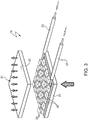
- thermoelectric circuit 15 comprises a series-parallel network of thermoelectric modules 16 subjected to said thermal gradient when drive means 7 are run.
- each thermoelectric module 16 comprises a number of semiconductor junction cells 20 fixed to a preferably ceramic substrate 21.
- cells 20 are P and N types, are fixed between two ceramic plates 22, and may, for example, be made of bismuth telluride.
- Each thermoelectric module 16 also comprises electric connecting means 23 for connection to other thermoelectric modules 16 and to the electric system of helicopter 1.
- thermoelectric modules 16 are fixed to the outside of a portion of the wall 24 of exhaust duct 8 corresponding to intermediate portion 11.
- wall 24 is lagged with a layer 25 of heat-insulating material, on which thermoelectric modules 16 are fixed, e.g. glued.
- layer 25 of heat-insulating material is interposed between wall 24 and thermoelectric modules 16.
- the thickness and thermal conductivity of the heat-insulating material of layer 25 are selected so that, when helicopter 1 is running, the temperature to which thermoelectric modules 16 are subjected from inside exhaust duct 8 never exceeds the maximum operating temperature of modules 16.
- thermoelectric modules 16 are covered on the outside, i.e. the opposite side to that contacting layer 25 of heat-insulating material, with heat-dissipating means 26 made, for example, of aluminium alloys or graphene-based materials.
- thermoelectric modules 16 are subjected to the desired thermal gradient, i.e. the desired difference in temperature between the outer side of modules 16 contacting dissipating means 26, and the inner side of modules 16 contacting layer 25 of heat-insulating material.
- thermoelectric modules 16 are divided into groups, each comprising a given number of series-connected modules 16; and the number of modules 16 to connect in series is calculated by dividing the voltage level V 0 of the electric system of helicopter 1 - normally 28Vdc - by the voltage supply V M of each module 16.
- thermoelectric circuit 15 The groups of modules 16 so calculated are then parallel-connected to one another to minimize the total resistance of thermoelectric circuit 15.
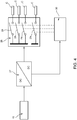
- the Figure 4 schematic shows how thermoelectric modules 16 are employed on helicopter 1.
- thermoelectric modules 16 are connected to a number of electric loads C on helicopter 1 by a DC/DC conversion unit 27 and a distribution unit 28.
- electric loads C are defined by the main battery and auxiliary battery of helicopter 1, and by non-safety-critical mission loads, such as auxiliary radios, video downlinks, video-cameras, auxiliary displays, searchlights, winches, etc.
- Conversion unit 27 stabilizes the voltage applied to electric loads C, to safeguard against significant fluctuations in the voltage of thermoelectric modules 16 caused by changes in temperature.
- the input impedance of conversion unit 27 is preferably adjustable, for example, as a function of the temperature of thermoelectric modules 16, i.e. by applying a thermocouple to thermoelectric modules 16; and conversion unit 27 maximizes power transfer from thermoelectric modules 16 to electric loads C, and ensures a minimum output voltage compatible with loads C.
- Distribution unit 28 comprises a number of switches 29 for selectively connecting respective electric loads C to conversion unit 27.
- Power supply to electric loads C by distribution unit 28, i.e. opening/closing of switches 29, is controlled by a control unit 30 as a function of available electric power and the operating status of helicopter 1.
- Available power can be calculated by control unit 30 on the basis of a related signal from conversion unit 27, or an internal algorithm, with no detection required.
- Control unit 30 provides for :
- Number 8' in Figure 6 indicates as a whole an exhaust duct in accordance with a variation of the present invention, and the component parts of which are indicated, where possible, using the same reference numbers as for corresponding or equivalent parts of exhaust duct 8 already described.
- thermoelectric modules 16 integrally define at least part of wall 24 of duct 8' at intermediate portion 11.
- Thermoelectric modules 16 are connected mechanically to one another and to the rest of wall 24.
- the solution described provides for converting part of the thermal energy lost in the exhaust gas directly into electric energy.
- the electric energy recovered from the exhaust gas is used directly to charge the main and auxiliary batteries and other electric loads C of the helicopter, and so reduces the power draw from drive means 7.
- the main and auxiliary batteries and electric loads C of helicopter 1 were powered by respective generators connected to drive means 7.
- thermoelectric modules 16 Direct connection of thermoelectric modules 16 to the batteries and other electric loads C of helicopter 1 obviously provides for significant fuel saving, increasing fuel range, and so reducing harmful emissions, particularly CO 2 .
- the generators normally installed on helicopter 1 may be downsized to reduce weight and volume.
- the batteries may be downsized, with respect to conventional solutions, and are no longer subject to certification regulations requiring a sufficient reserve to power essential electric loads for at least 30 minutes in emergency conditions.
- the additional Seebeck-effect electric energy supplied in all flying conditions also provides a solution to the electric power limitations at high altitude or in low-pitch ground conditions.
- thermoelectric circuit 15 forming an additional electric power source by which to battery-power essential electric loads on helicopter 1, in the event both generators fail.
- the innovative solution described also has the advantage of increasing the cooling margin and so reducing thermal stress of exhaust ducts 8, 8'.
- the solution described and illustrated also has a long working life, no rotating parts, and requires no particular maintenance.
- thermoelectric modules 16 may advantageously be in the form of 'macromodules', each defining an electric subnetwork, to increase the power output of each module.
- heat-dissipating means 26 may be integrated in the structural mounts of exhaust ducts 8, 8'.
Priority Applications (1)
| Application Number | Priority Date | Filing Date | Title |
|---|---|---|---|
| EP12160021.7A EP2500270B1 (fr) | 2011-03-18 | 2012-03-17 | Avion capable de vol stationnaire |
Applications Claiming Priority (2)
| Application Number | Priority Date | Filing Date | Title |
|---|---|---|---|
| EP11425066A EP2500269A1 (fr) | 2011-03-18 | 2011-03-18 | Avion capable de vol stationnaire |
| EP12160021.7A EP2500270B1 (fr) | 2011-03-18 | 2012-03-17 | Avion capable de vol stationnaire |
Publications (4)
| Publication Number | Publication Date |
|---|---|
| EP2500270A2 true EP2500270A2 (fr) | 2012-09-19 |
| EP2500270A8 EP2500270A8 (fr) | 2012-12-12 |
| EP2500270A3 EP2500270A3 (fr) | 2013-10-23 |
| EP2500270B1 EP2500270B1 (fr) | 2015-08-26 |
Family
ID=45814428
Family Applications (2)
| Application Number | Title | Priority Date | Filing Date |
|---|---|---|---|
| EP11425066A Withdrawn EP2500269A1 (fr) | 2011-03-18 | 2011-03-18 | Avion capable de vol stationnaire |
| EP12160021.7A Active EP2500270B1 (fr) | 2011-03-18 | 2012-03-17 | Avion capable de vol stationnaire |
Family Applications Before (1)
| Application Number | Title | Priority Date | Filing Date |
|---|---|---|---|
| EP11425066A Withdrawn EP2500269A1 (fr) | 2011-03-18 | 2011-03-18 | Avion capable de vol stationnaire |
Country Status (7)
| Country | Link |
|---|---|
| US (1) | US8939397B2 (fr) |
| EP (2) | EP2500269A1 (fr) |
| JP (1) | JP2012197073A (fr) |
| KR (1) | KR101872867B1 (fr) |
| CN (1) | CN102689691B (fr) |
| IN (1) | IN2012DE00783A (fr) |
| RU (1) | RU2595735C2 (fr) |
Families Citing this family (11)
| Publication number | Priority date | Publication date | Assignee | Title |
|---|---|---|---|---|
| US9666781B2 (en) * | 2013-08-19 | 2017-05-30 | The Boeing Company | Methods for recovering waste energy from bleed air ducts |
| JP2015039925A (ja) * | 2013-08-21 | 2015-03-02 | 株式会社Ihiエアロスペース | スラスタ用熱エネルギ回収装置 |
| EP2868896A1 (fr) * | 2013-11-05 | 2015-05-06 | Rolls-Royce Deutschland Ltd & Co KG | Turbomachine avec dispositif de récupération d'énergie, dispositif de récupération d'énergie et procédé de récupération d'énergie |
| CN105217046B (zh) * | 2015-09-28 | 2017-08-29 | 易瓦特科技股份公司 | 具有柔性排气管的排气通道 |
| FR3042539B1 (fr) * | 2015-10-16 | 2017-11-24 | Labinal Power Systems | Systeme anti-flexion pour turbomachine d'aeronef |
| US10291156B2 (en) | 2015-10-30 | 2019-05-14 | Ge Aviation Systems Llc | Combined hybrid thermionic and thermoelectric generator |
| GB2559956B (en) * | 2017-02-15 | 2020-09-16 | Ge Aviat Systems Ltd | Power distribution node for a power architecture |
| US10366909B2 (en) * | 2017-07-27 | 2019-07-30 | Taiwan Semiconductor Manufacturing Company, Ltd. | Thermal chamber exhaust structure and method |
| CN109606709A (zh) * | 2018-11-14 | 2019-04-12 | 中国直升机设计研究所 | 一种用于直升机的排气管安装结构 |
| KR102407759B1 (ko) * | 2020-10-13 | 2022-06-13 | 현대오토에버 주식회사 | 비행체용 전력 분배 시스템 및 방법 |
| WO2022095008A1 (fr) * | 2020-11-09 | 2022-05-12 | 常州机电职业技术学院 | Dispositif de recyclage de chaleur perdue pour système d'échappement d'automobile et procédé de recyclage |
Family Cites Families (29)
| Publication number | Priority date | Publication date | Assignee | Title |
|---|---|---|---|---|
| US3879229A (en) * | 1972-04-19 | 1975-04-22 | William W Gilbert | Tubular thermopile |
| DE2433591A1 (de) * | 1974-07-12 | 1976-01-22 | Otto Pulch | Thermoelektrischer generator |
| US4018046A (en) * | 1975-07-17 | 1977-04-19 | Avco Corporation | Infrared radiation suppressor for gas turbine engine |
| GB2044359B (en) * | 1979-03-16 | 1982-10-27 | Rolls Royce | Gas turbine engine air intakes |
| GB2114229B (en) * | 1981-11-03 | 1984-11-21 | Rolls Royce | Gas turbine engine infra-red radiation suppressor |
| SU1285168A1 (ru) * | 1985-08-01 | 1987-01-23 | Институт технической теплофизики АН УССР | Глушитель шума выхлопа двигател внутреннего сгорани |
| US5699965A (en) * | 1989-06-30 | 1997-12-23 | Sikorsky Aircraft Corporation | Infrared suppressor for a gas turbine engine |
| US6134879A (en) * | 1989-12-21 | 2000-10-24 | United Technologies Corporation | Suppression system for a gas turbine engine |
| JP2691051B2 (ja) * | 1990-05-28 | 1997-12-17 | 三菱重工業株式会社 | 航空機用ガスタービンエンジン |
| US5554819A (en) * | 1992-01-22 | 1996-09-10 | Baghai-Kermani; A. | Method and apparatus for the thermoelectric generation of electricity |
| WO2001061768A1 (fr) * | 2000-02-18 | 2001-08-23 | Motorola Inc. | Generateur de puissance thermoelectrique destine un aeronef |
| CN1330083C (zh) * | 2003-05-16 | 2007-08-01 | 浙江大学 | 一种热电式微型电源 |
| CN100397671C (zh) * | 2003-10-29 | 2008-06-25 | 京瓷株式会社 | 热电换能模块 |
| JP2005269713A (ja) * | 2004-03-16 | 2005-09-29 | Toyota Motor Corp | 熱発電装置 |
| JP2005295725A (ja) * | 2004-04-01 | 2005-10-20 | Toyota Motor Corp | 熱電発電装置 |
| JP2006062439A (ja) * | 2004-08-25 | 2006-03-09 | Ishikawajima Harima Heavy Ind Co Ltd | 熱気球の電源装置 |
| US20060118157A1 (en) * | 2004-12-03 | 2006-06-08 | Caterpillar Inc | Thermoelectric generator and control system |
| JP2009087955A (ja) * | 2005-01-12 | 2009-04-23 | Showa Denko Kk | 熱電変換システムを有する廃熱回収システム |
| FR2900386B1 (fr) * | 2006-04-28 | 2008-06-20 | Eurocopter France | Installation motrice pour aeronef a voilure tournante |
| KR20090020685A (ko) * | 2006-06-09 | 2009-02-26 | 벨 헬리콥터 텍스트론 인크. | 방향성 노즐을 갖는 엔진 배기 시스템 |
| US7985918B2 (en) * | 2006-12-14 | 2011-07-26 | Thermohex, Llc | Thermoelectric module |
| US8100216B2 (en) * | 2006-12-19 | 2012-01-24 | Bradley Wayne Bartilson | Hybrid drivetrain with waste heat energy conversion into electricity |
| US9018512B2 (en) * | 2007-12-21 | 2015-04-28 | The Boeing Company | Thermoelectric generation system |
| JP2009293390A (ja) * | 2008-06-02 | 2009-12-17 | Honda Motor Co Ltd | ガスタービンエンジン |
| FR2942077B1 (fr) * | 2009-02-06 | 2013-08-16 | Turbomeca | Generation thermoelectrique pour turbine a gaz |
| FR2945268B1 (fr) * | 2009-05-05 | 2013-05-17 | Airbus France | Generateur electrique sur une partie tournante de turbopropulseur |
| US8484983B2 (en) * | 2009-12-07 | 2013-07-16 | The Boeing Company | Thermoelectric generator on an aircraft bleed system |
| US8578696B2 (en) * | 2010-08-03 | 2013-11-12 | General Electric Company | Turbulated arrangement of thermoelectric elements for utilizing waste heat generated from turbine engine |
| US20120118345A1 (en) * | 2010-11-15 | 2012-05-17 | The Boeing Company | Thermal integration of thermoelectronic device |
-
2011
- 2011-03-18 EP EP11425066A patent/EP2500269A1/fr not_active Withdrawn
-
2012
- 2012-03-16 US US13/422,855 patent/US8939397B2/en active Active
- 2012-03-16 JP JP2012059546A patent/JP2012197073A/ja not_active Ceased
- 2012-03-16 IN IN783DE2012 patent/IN2012DE00783A/en unknown
- 2012-03-16 RU RU2012110189/11A patent/RU2595735C2/ru active
- 2012-03-17 EP EP12160021.7A patent/EP2500270B1/fr active Active
- 2012-03-19 KR KR1020120027872A patent/KR101872867B1/ko active IP Right Grant
- 2012-03-19 CN CN201210073379.XA patent/CN102689691B/zh active Active
Non-Patent Citations (1)
| Title |
|---|
| None |
Also Published As
| Publication number | Publication date |
|---|---|
| EP2500270A8 (fr) | 2012-12-12 |
| KR20120106660A (ko) | 2012-09-26 |
| RU2595735C2 (ru) | 2016-08-27 |
| EP2500270B1 (fr) | 2015-08-26 |
| CN102689691B (zh) | 2016-02-17 |
| CN102689691A (zh) | 2012-09-26 |
| RU2012110189A (ru) | 2013-09-27 |
| KR101872867B1 (ko) | 2018-07-02 |
| EP2500270A3 (fr) | 2013-10-23 |
| US20120233988A1 (en) | 2012-09-20 |
| EP2500269A1 (fr) | 2012-09-19 |
| US8939397B2 (en) | 2015-01-27 |
| IN2012DE00783A (fr) | 2015-08-21 |
| JP2012197073A (ja) | 2012-10-18 |
Similar Documents
| Publication | Publication Date | Title |
|---|---|---|
| EP2500270B1 (fr) | Avion capable de vol stationnaire | |
| US20210039798A1 (en) | Propulsion system and methods of use thereof | |
| US10138899B2 (en) | Electric propulsion assembly for an aircraft | |
| EP4058360A2 (fr) | Systèmes et procédés pour aéronef | |
| EP2509869B1 (fr) | Générateur thermoélectrique sur un système de prélèvement d'air à bord d'un avion | |
| US11738874B2 (en) | Aircraft having hybrid-electric propulsion system with electric storage located in fuselage | |
| CN110521106A (zh) | 电驱动机构和用于向电驱动机构馈电的方法 | |
| US10562641B2 (en) | AFT exhaust system for rotary wing aircraft | |
| US20210031934A1 (en) | Aircraft having hybrid-electric propulsion system with electric storage located in fuselage | |
| GB2538982A (en) | Self-contained, electric contra rotating propeller propulsion apparatus for aircraft | |
| US20240116627A1 (en) | System and Methods for Lifter Motor Cooling in EVTOL Aircraft | |
| US11866169B2 (en) | System and method for supplying passively filtered ram air to a hydrogen fuel cell of a UAV | |
| CN205022878U (zh) | 无人直升机 | |
| RU2677741C1 (ru) | Летательный аппарат |
Legal Events
| Date | Code | Title | Description |
|---|---|---|---|
| PUAI | Public reference made under article 153(3) epc to a published international application that has entered the european phase |
Free format text: ORIGINAL CODE: 0009012 |
|
| AK | Designated contracting states |
Kind code of ref document: A2 Designated state(s): AL AT BE BG CH CY CZ DE DK EE ES FI FR GB GR HR HU IE IS IT LI LT LU LV MC MK MT NL NO PL PT RO RS SE SI SK SM TR |
|
| AX | Request for extension of the european patent |
Extension state: BA ME |
|
| RIN1 | Information on inventor provided before grant (corrected) |
Inventor name: SCANDROGLIO, ALESSANDRO Inventor name: COGLIATI, ANDREA Inventor name: IANNUCCI, DARIO Inventor name: BRUNETTI, MASSIMO |
|
| PUAL | Search report despatched |
Free format text: ORIGINAL CODE: 0009013 |
|
| AK | Designated contracting states |
Kind code of ref document: A3 Designated state(s): AL AT BE BG CH CY CZ DE DK EE ES FI FR GB GR HR HU IE IS IT LI LT LU LV MC MK MT NL NO PL PT RO RS SE SI SK SM TR |
|
| AX | Request for extension of the european patent |
Extension state: BA ME |
|
| RIC1 | Information provided on ipc code assigned before grant |
Ipc: H01L 35/28 20060101ALI20130919BHEP Ipc: F01D 25/30 20060101ALI20130919BHEP Ipc: B64D 33/04 20060101AFI20130919BHEP Ipc: F02K 1/82 20060101ALI20130919BHEP Ipc: H01L 35/30 20060101ALI20130919BHEP |
|
| 17P | Request for examination filed |
Effective date: 20140423 |
|
| RBV | Designated contracting states (corrected) |
Designated state(s): AL AT BE BG CH CY CZ DE DK EE ES FI FR GB GR HR HU IE IS IT LI LT LU LV MC MK MT NL NO PL PT RO RS SE SI SK SM TR |
|
| RAP1 | Party data changed (applicant data changed or rights of an application transferred) |
Owner name: AGUSTAWESTLAND S.P.A. |
|
| GRAP | Despatch of communication of intention to grant a patent |
Free format text: ORIGINAL CODE: EPIDOSNIGR1 |
|
| INTG | Intention to grant announced |
Effective date: 20150306 |
|
| RAP1 | Party data changed (applicant data changed or rights of an application transferred) |
Owner name: AGUSTAWESTLAND S.P.A. |
|
| GRAS | Grant fee paid |
Free format text: ORIGINAL CODE: EPIDOSNIGR3 |
|
| GRAA | (expected) grant |
Free format text: ORIGINAL CODE: 0009210 |
|
| AK | Designated contracting states |
Kind code of ref document: B1 Designated state(s): AL AT BE BG CH CY CZ DE DK EE ES FI FR GB GR HR HU IE IS IT LI LT LU LV MC MK MT NL NO PL PT RO RS SE SI SK SM TR |
|
| REG | Reference to a national code |
Ref country code: GB Ref legal event code: FG4D |
|
| RIN1 | Information on inventor provided before grant (corrected) |
Inventor name: IANNUCCI, DARIO Inventor name: SCANDROGLIO, ALESSANDRO Inventor name: BRUNETTI, MASSIMO Inventor name: COGLIATI, ANDREA |
|
| REG | Reference to a national code |
Ref country code: CH Ref legal event code: EP |
|
| REG | Reference to a national code |
Ref country code: AT Ref legal event code: REF Ref document number: 745022 Country of ref document: AT Kind code of ref document: T Effective date: 20150915 |
|
| REG | Reference to a national code |
Ref country code: IE Ref legal event code: FG4D |
|
| REG | Reference to a national code |
Ref country code: DE Ref legal event code: R096 Ref document number: 602012009920 Country of ref document: DE |
|
| REG | Reference to a national code |
Ref country code: AT Ref legal event code: MK05 Ref document number: 745022 Country of ref document: AT Kind code of ref document: T Effective date: 20150826 |
|
| REG | Reference to a national code |
Ref country code: LT Ref legal event code: MG4D |
|
| PG25 | Lapsed in a contracting state [announced via postgrant information from national office to epo] |
Ref country code: LV Free format text: LAPSE BECAUSE OF FAILURE TO SUBMIT A TRANSLATION OF THE DESCRIPTION OR TO PAY THE FEE WITHIN THE PRESCRIBED TIME-LIMIT Effective date: 20150826 Ref country code: FI Free format text: LAPSE BECAUSE OF FAILURE TO SUBMIT A TRANSLATION OF THE DESCRIPTION OR TO PAY THE FEE WITHIN THE PRESCRIBED TIME-LIMIT Effective date: 20150826 Ref country code: NO Free format text: LAPSE BECAUSE OF FAILURE TO SUBMIT A TRANSLATION OF THE DESCRIPTION OR TO PAY THE FEE WITHIN THE PRESCRIBED TIME-LIMIT Effective date: 20151126 Ref country code: LT Free format text: LAPSE BECAUSE OF FAILURE TO SUBMIT A TRANSLATION OF THE DESCRIPTION OR TO PAY THE FEE WITHIN THE PRESCRIBED TIME-LIMIT Effective date: 20150826 Ref country code: GR Free format text: LAPSE BECAUSE OF FAILURE TO SUBMIT A TRANSLATION OF THE DESCRIPTION OR TO PAY THE FEE WITHIN THE PRESCRIBED TIME-LIMIT Effective date: 20151127 |
|
| REG | Reference to a national code |
Ref country code: NL Ref legal event code: MP Effective date: 20150826 |
|
| REG | Reference to a national code |
Ref country code: FR Ref legal event code: PLFP Year of fee payment: 5 |
|
| PG25 | Lapsed in a contracting state [announced via postgrant information from national office to epo] |
Ref country code: ES Free format text: LAPSE BECAUSE OF FAILURE TO SUBMIT A TRANSLATION OF THE DESCRIPTION OR TO PAY THE FEE WITHIN THE PRESCRIBED TIME-LIMIT Effective date: 20150826 Ref country code: PT Free format text: LAPSE BECAUSE OF FAILURE TO SUBMIT A TRANSLATION OF THE DESCRIPTION OR TO PAY THE FEE WITHIN THE PRESCRIBED TIME-LIMIT Effective date: 20151228 Ref country code: RS Free format text: LAPSE BECAUSE OF FAILURE TO SUBMIT A TRANSLATION OF THE DESCRIPTION OR TO PAY THE FEE WITHIN THE PRESCRIBED TIME-LIMIT Effective date: 20150826 Ref country code: AT Free format text: LAPSE BECAUSE OF FAILURE TO SUBMIT A TRANSLATION OF THE DESCRIPTION OR TO PAY THE FEE WITHIN THE PRESCRIBED TIME-LIMIT Effective date: 20150826 Ref country code: IS Free format text: LAPSE BECAUSE OF FAILURE TO SUBMIT A TRANSLATION OF THE DESCRIPTION OR TO PAY THE FEE WITHIN THE PRESCRIBED TIME-LIMIT Effective date: 20151226 Ref country code: SE Free format text: LAPSE BECAUSE OF FAILURE TO SUBMIT A TRANSLATION OF THE DESCRIPTION OR TO PAY THE FEE WITHIN THE PRESCRIBED TIME-LIMIT Effective date: 20150826 Ref country code: HR Free format text: LAPSE BECAUSE OF FAILURE TO SUBMIT A TRANSLATION OF THE DESCRIPTION OR TO PAY THE FEE WITHIN THE PRESCRIBED TIME-LIMIT Effective date: 20150826 Ref country code: PL Free format text: LAPSE BECAUSE OF FAILURE TO SUBMIT A TRANSLATION OF THE DESCRIPTION OR TO PAY THE FEE WITHIN THE PRESCRIBED TIME-LIMIT Effective date: 20150826 |
|
| PG25 | Lapsed in a contracting state [announced via postgrant information from national office to epo] |
Ref country code: NL Free format text: LAPSE BECAUSE OF FAILURE TO SUBMIT A TRANSLATION OF THE DESCRIPTION OR TO PAY THE FEE WITHIN THE PRESCRIBED TIME-LIMIT Effective date: 20150826 |
|
| PG25 | Lapsed in a contracting state [announced via postgrant information from national office to epo] |
Ref country code: SK Free format text: LAPSE BECAUSE OF FAILURE TO SUBMIT A TRANSLATION OF THE DESCRIPTION OR TO PAY THE FEE WITHIN THE PRESCRIBED TIME-LIMIT Effective date: 20150826 Ref country code: CZ Free format text: LAPSE BECAUSE OF FAILURE TO SUBMIT A TRANSLATION OF THE DESCRIPTION OR TO PAY THE FEE WITHIN THE PRESCRIBED TIME-LIMIT Effective date: 20150826 Ref country code: EE Free format text: LAPSE BECAUSE OF FAILURE TO SUBMIT A TRANSLATION OF THE DESCRIPTION OR TO PAY THE FEE WITHIN THE PRESCRIBED TIME-LIMIT Effective date: 20150826 Ref country code: DK Free format text: LAPSE BECAUSE OF FAILURE TO SUBMIT A TRANSLATION OF THE DESCRIPTION OR TO PAY THE FEE WITHIN THE PRESCRIBED TIME-LIMIT Effective date: 20150826 |
|
| REG | Reference to a national code |
Ref country code: DE Ref legal event code: R097 Ref document number: 602012009920 Country of ref document: DE |
|
| PG25 | Lapsed in a contracting state [announced via postgrant information from national office to epo] |
Ref country code: RO Free format text: LAPSE BECAUSE OF FAILURE TO SUBMIT A TRANSLATION OF THE DESCRIPTION OR TO PAY THE FEE WITHIN THE PRESCRIBED TIME-LIMIT Effective date: 20150826 |
|
| PLBE | No opposition filed within time limit |
Free format text: ORIGINAL CODE: 0009261 |
|
| STAA | Information on the status of an ep patent application or granted ep patent |
Free format text: STATUS: NO OPPOSITION FILED WITHIN TIME LIMIT |
|
| 26N | No opposition filed |
Effective date: 20160530 |
|
| PG25 | Lapsed in a contracting state [announced via postgrant information from national office to epo] |
Ref country code: SI Free format text: LAPSE BECAUSE OF FAILURE TO SUBMIT A TRANSLATION OF THE DESCRIPTION OR TO PAY THE FEE WITHIN THE PRESCRIBED TIME-LIMIT Effective date: 20150826 Ref country code: BE Free format text: LAPSE BECAUSE OF NON-PAYMENT OF DUE FEES Effective date: 20160331 |
|
| PG25 | Lapsed in a contracting state [announced via postgrant information from national office to epo] |
Ref country code: MC Free format text: LAPSE BECAUSE OF FAILURE TO SUBMIT A TRANSLATION OF THE DESCRIPTION OR TO PAY THE FEE WITHIN THE PRESCRIBED TIME-LIMIT Effective date: 20150826 Ref country code: LU Free format text: LAPSE BECAUSE OF FAILURE TO SUBMIT A TRANSLATION OF THE DESCRIPTION OR TO PAY THE FEE WITHIN THE PRESCRIBED TIME-LIMIT Effective date: 20160317 |
|
| REG | Reference to a national code |
Ref country code: CH Ref legal event code: PL |
|
| REG | Reference to a national code |
Ref country code: IE Ref legal event code: MM4A |
|
| PG25 | Lapsed in a contracting state [announced via postgrant information from national office to epo] |
Ref country code: BE Free format text: LAPSE BECAUSE OF FAILURE TO SUBMIT A TRANSLATION OF THE DESCRIPTION OR TO PAY THE FEE WITHIN THE PRESCRIBED TIME-LIMIT Effective date: 20150826 |
|
| PG25 | Lapsed in a contracting state [announced via postgrant information from national office to epo] |
Ref country code: LI Free format text: LAPSE BECAUSE OF NON-PAYMENT OF DUE FEES Effective date: 20160331 Ref country code: CH Free format text: LAPSE BECAUSE OF NON-PAYMENT OF DUE FEES Effective date: 20160331 Ref country code: IE Free format text: LAPSE BECAUSE OF NON-PAYMENT OF DUE FEES Effective date: 20160317 |
|
| REG | Reference to a national code |
Ref country code: FR Ref legal event code: PLFP Year of fee payment: 6 |
|
| PG25 | Lapsed in a contracting state [announced via postgrant information from national office to epo] |
Ref country code: MT Free format text: LAPSE BECAUSE OF FAILURE TO SUBMIT A TRANSLATION OF THE DESCRIPTION OR TO PAY THE FEE WITHIN THE PRESCRIBED TIME-LIMIT Effective date: 20150826 |
|
| REG | Reference to a national code |
Ref country code: FR Ref legal event code: PLFP Year of fee payment: 7 |
|
| PG25 | Lapsed in a contracting state [announced via postgrant information from national office to epo] |
Ref country code: CY Free format text: LAPSE BECAUSE OF FAILURE TO SUBMIT A TRANSLATION OF THE DESCRIPTION OR TO PAY THE FEE WITHIN THE PRESCRIBED TIME-LIMIT Effective date: 20150826 Ref country code: SM Free format text: LAPSE BECAUSE OF FAILURE TO SUBMIT A TRANSLATION OF THE DESCRIPTION OR TO PAY THE FEE WITHIN THE PRESCRIBED TIME-LIMIT Effective date: 20150826 Ref country code: HU Free format text: LAPSE BECAUSE OF FAILURE TO SUBMIT A TRANSLATION OF THE DESCRIPTION OR TO PAY THE FEE WITHIN THE PRESCRIBED TIME-LIMIT; INVALID AB INITIO Effective date: 20120317 |
|
| PG25 | Lapsed in a contracting state [announced via postgrant information from national office to epo] |
Ref country code: MK Free format text: LAPSE BECAUSE OF FAILURE TO SUBMIT A TRANSLATION OF THE DESCRIPTION OR TO PAY THE FEE WITHIN THE PRESCRIBED TIME-LIMIT Effective date: 20150826 Ref country code: TR Free format text: LAPSE BECAUSE OF FAILURE TO SUBMIT A TRANSLATION OF THE DESCRIPTION OR TO PAY THE FEE WITHIN THE PRESCRIBED TIME-LIMIT Effective date: 20150826 Ref country code: MT Free format text: LAPSE BECAUSE OF FAILURE TO SUBMIT A TRANSLATION OF THE DESCRIPTION OR TO PAY THE FEE WITHIN THE PRESCRIBED TIME-LIMIT Effective date: 20160331 |
|
| PG25 | Lapsed in a contracting state [announced via postgrant information from national office to epo] |
Ref country code: BG Free format text: LAPSE BECAUSE OF FAILURE TO SUBMIT A TRANSLATION OF THE DESCRIPTION OR TO PAY THE FEE WITHIN THE PRESCRIBED TIME-LIMIT Effective date: 20150826 |
|
| PG25 | Lapsed in a contracting state [announced via postgrant information from national office to epo] |
Ref country code: AL Free format text: LAPSE BECAUSE OF FAILURE TO SUBMIT A TRANSLATION OF THE DESCRIPTION OR TO PAY THE FEE WITHIN THE PRESCRIBED TIME-LIMIT Effective date: 20150826 |
|
| REG | Reference to a national code |
Ref country code: DE Ref legal event code: R082 Ref document number: 602012009920 Country of ref document: DE Representative=s name: TER MEER STEINMEISTER & PARTNER PATENTANWAELTE, DE Ref country code: DE Ref legal event code: R081 Ref document number: 602012009920 Country of ref document: DE Owner name: LEONARDO S.P.A., IT Free format text: FORMER OWNER: AGUSTAWESTLAND S.P.A, ROM, IT |
|
| PGFP | Annual fee paid to national office [announced via postgrant information from national office to epo] |
Ref country code: FR Payment date: 20230323 Year of fee payment: 12 |
|
| PGFP | Annual fee paid to national office [announced via postgrant information from national office to epo] |
Ref country code: IT Payment date: 20230306 Year of fee payment: 12 |
|
| P01 | Opt-out of the competence of the unified patent court (upc) registered |
Effective date: 20231005 |
|
| PGFP | Annual fee paid to national office [announced via postgrant information from national office to epo] |
Ref country code: DE Payment date: 20240328 Year of fee payment: 13 Ref country code: GB Payment date: 20240319 Year of fee payment: 13 |