EP2500122A1 - Rohrentgrater, insbesondere für Rohre von Pressfitting-Systemen, sowie Entgrareinrichtung mit einem solchen Rohrengrater - Google Patents
Rohrentgrater, insbesondere für Rohre von Pressfitting-Systemen, sowie Entgrareinrichtung mit einem solchen Rohrengrater Download PDFInfo
- Publication number
- EP2500122A1 EP2500122A1 EP12001116A EP12001116A EP2500122A1 EP 2500122 A1 EP2500122 A1 EP 2500122A1 EP 12001116 A EP12001116 A EP 12001116A EP 12001116 A EP12001116 A EP 12001116A EP 2500122 A1 EP2500122 A1 EP 2500122A1
- Authority
- EP
- European Patent Office
- Prior art keywords
- deburring
- pipe
- housing
- friction
- deburring device
- Prior art date
- Legal status (The legal status is an assumption and is not a legal conclusion. Google has not performed a legal analysis and makes no representation as to the accuracy of the status listed.)
- Granted
Links
- 238000005520 cutting process Methods 0.000 claims description 45
- 230000002093 peripheral effect Effects 0.000 claims description 8
- 230000005540 biological transmission Effects 0.000 claims description 4
- 238000000034 method Methods 0.000 description 7
- 238000000926 separation method Methods 0.000 description 6
- RYGMFSIKBFXOCR-UHFFFAOYSA-N Copper Chemical compound [Cu] RYGMFSIKBFXOCR-UHFFFAOYSA-N 0.000 description 3
- 229910052802 copper Inorganic materials 0.000 description 3
- 239000010949 copper Substances 0.000 description 3
- 239000004033 plastic Substances 0.000 description 3
- 229910001220 stainless steel Inorganic materials 0.000 description 3
- 239000010935 stainless steel Substances 0.000 description 3
- 238000004026 adhesive bonding Methods 0.000 description 2
- 239000002783 friction material Substances 0.000 description 2
- 230000000284 resting effect Effects 0.000 description 2
- 238000005476 soldering Methods 0.000 description 2
- 238000003466 welding Methods 0.000 description 2
- 229910000831 Steel Inorganic materials 0.000 description 1
- 238000010276 construction Methods 0.000 description 1
- 238000005516 engineering process Methods 0.000 description 1
- 238000009434 installation Methods 0.000 description 1
- 238000004519 manufacturing process Methods 0.000 description 1
- 239000007769 metal material Substances 0.000 description 1
- 238000010079 rubber tapping Methods 0.000 description 1
- 238000007789 sealing Methods 0.000 description 1
- 239000010959 steel Substances 0.000 description 1
- 230000008719 thickening Effects 0.000 description 1
- 230000007704 transition Effects 0.000 description 1
Images
Classifications
-
- B—PERFORMING OPERATIONS; TRANSPORTING
- B23—MACHINE TOOLS; METAL-WORKING NOT OTHERWISE PROVIDED FOR
- B23B—TURNING; BORING
- B23B5/00—Turning-machines or devices specially adapted for particular work; Accessories specially adapted therefor
- B23B5/16—Turning-machines or devices specially adapted for particular work; Accessories specially adapted therefor for bevelling, chamfering, or deburring the ends of bars or tubes
- B23B5/165—Workpieces clamped on a bench, e.g. a vice
-
- B—PERFORMING OPERATIONS; TRANSPORTING
- B23—MACHINE TOOLS; METAL-WORKING NOT OTHERWISE PROVIDED FOR
- B23B—TURNING; BORING
- B23B5/00—Turning-machines or devices specially adapted for particular work; Accessories specially adapted therefor
- B23B5/16—Turning-machines or devices specially adapted for particular work; Accessories specially adapted therefor for bevelling, chamfering, or deburring the ends of bars or tubes
- B23B5/167—Tools for chamfering the ends of bars or tubes
- B23B5/168—Tools for chamfering the ends of bars or tubes with guiding devices
-
- B—PERFORMING OPERATIONS; TRANSPORTING
- B23—MACHINE TOOLS; METAL-WORKING NOT OTHERWISE PROVIDED FOR
- B23B—TURNING; BORING
- B23B51/00—Tools for drilling machines
- B23B51/10—Bits for countersinking
- B23B51/103—Deburring or chamfering tools for the ends of tubes or rods
-
- B—PERFORMING OPERATIONS; TRANSPORTING
- B23—MACHINE TOOLS; METAL-WORKING NOT OTHERWISE PROVIDED FOR
- B23D—PLANING; SLOTTING; SHEARING; BROACHING; SAWING; FILING; SCRAPING; LIKE OPERATIONS FOR WORKING METAL BY REMOVING MATERIAL, NOT OTHERWISE PROVIDED FOR
- B23D21/00—Machines or devices for shearing or cutting tubes
- B23D21/006—Machines or devices for shearing or cutting tubes and sealing, crushing or chamfering the tubes
Definitions
- the invention relates to a pipe deburrer, in particular for pipes of press fitting systems, according to the preamble of claim 1 and a deburring device with such a pipe deburrer according to the preamble of claim 6.
- pipes of stainless steel, copper and plastic for the installation of press fitting systems are advantageously separated with tools with a cutting wheel. This creates only a minimal outer ridge.
- a more or less strong inner burr is produced by the non-cutting separation process with the cutting wheel.
- multi-tooth pipe deburrers are used, which are pressed by hand, possibly driven by a drill, against the severed pipe.
- the pipe section to be deburred is usually held by hand. For pipes with a larger diameter up to about 108 mm this is However, technology is not possible because neither the pipe sections nor a correspondingly heavy, large and thus unwieldy pipe deburrer can be held with one hand.
- the invention is therefore the object of the generic deburring device and the generic deburring device in such a way that the pipes, especially of press fitting systems, can be easily and inexpensively deburred even with large pipe diameter.
- the pipe deburrer according to the invention has a housing which is provided on its cylindrical outer side with at least one peripheral friction element. With its help, it is possible to rotatably drive the Rohrentgrater about its axis, so that the pipe to be deburred, even if it should have a large diameter, can be held by hand. On circumferentially provided on the housing friction element can engage a friction wheel, which sets the Rohrentgrater in rotation.
- the pipe to be deburred does not have to be turned around its axis so that the deburring process can be carried out without problems.
- the friction element is attached to the housing of the Rohrentgraters Reibkranz. It can be provided at least on its upper side with a corresponding friction lining or be made entirely from a corresponding friction material.
- the friction element is provided with a circumferential recess.
- a deburring blade is advantageously used, which projects with at least one blade part either outwardly over the housing and / or inwardly over the inner wall of the housing.
- a mecanical gulft With the outwardly projecting blade part a mecanical gulfung can be made while with the on the inside of the housing projecting blade part, the tube can be deburred on the outside.
- the deburring blade is a simple and inexpensive to manufacture component that can be easily installed in the housing.
- the deburring part is advantageously fastened in the housing by at least one securing element.
- the securing element is provided so that it presses the deburring in its mounting position within the housing.
- the roller support is provided, which has at least two spaced-apart, freely rotatable rollers. They form the support for the pipe deburrer, which is placed on the parallel freely rotating rollers.
- the deburring device is provided with a rotatably driven friction wheel, which is brought to the rotary drive of the Rohrentgraters in frictional engagement with the friction element of the Rohrentgraters. The friction wheel abuts with its lateral surface on the lateral surface of the friction element. Since the friction wheel is rotatably driven, by the frictional engagement of the Rohrentgrater on the rollers driven in rotation about its axis.
- the friction wheel can advantageously be adjusted transversely to its axis of rotation. In this way, the contact pressure of the friction wheel can be adjusted on the friction element.
- the friction wheel is adjusted along a stand.
- a threaded spindle is accommodated in the stator. It is provided parallel to a straight guide in the stator for the adjustment of the friction wheel.
- a spindle nut On the threaded spindle sits a spindle nut which is connected to a motor / gear housing. Depending on the direction of rotation of the threaded spindle, the motor / gearbox housing is adjusted upwards or downwards via the spindle nut.
- the threaded spindle allows a stepless adjustment of the motor / gear housing.
- a motor / gearbox is provided for the friction wheel, which is thus adjusted by adjusting the engine / transmission housing in the respective position.
- the friction wheel is a cutting wheel for severing the tube.
- a deburring on the pipe can be performed with the deburring. It is placed on the freely rotating rollers.
- the cutting wheel is moved against the pipe to be separated. Since the cutting wheel is rotatably driven, and the tube lying on the freely rotatable rollers in rotation offset around its axis as soon as the cutting wheel engages the pipe. In this way, the tube is rotated about its axis and severed by means of the rotatably driven cutting wheel.
- This cutting wheel is used as a friction wheel during the deburring process. So that the cutting wheel does not damage or even destroy the friction element of the pipe deburrer with its peripheral cutting edge, the peripheral cutting edge engages in the circumferential depression of the friction element of the pipe deburrer.
- the recess is formed so that the peripheral edge does not come into contact with the bottom of the recess.
- the cylindrical lateral surface can be used in the area adjacent to the peripheral cutting edge of the cutting wheel for the frictional engagement with the friction element in order to rotate the tube deburrer resting on the rollers for the deburring process about its axis.
- the pipe deburrer and the friction wheel advantageously have mutually parallel axes of rotation. As a result, a simple rotation of the Rohrentgraters is ensured by the frictional engagement with the friction wheel.
- the deburring device described below is used for the internal de-sealing of pipes of pressfitting systems.
- Such pipes in press fitting systems are usually made of stainless steel, copper or plastic.
- tubes are deburred inside, which have larger diameters, for example in the range from 28 to 108 mm.
- the deburring device has a pipe deburrer with a deburrer housing 1 ( Fig. 1 and 5 to 8 ), which advantageously consists of metallic material.
- the deburrer housing 1 has a cylindrical part 2 and a cone part 3, which adjoins the one end of the cylindrical part 2.
- the two parts 2, 3 are separate parts which are firmly connected to each other, for example by gluing, soldering or welding.
- a friction ring 4 is connected, which is annular and projects radially inwardly over the inner wall of the cylinder part 2 ( Fig. 4 and 8th ).
- the friction ring 4 has an axial annular projection 5, with which it engages in an open towards the front side annular recess 6 in the outer side of the cylinder part 2.
- the friction ring 4 has in its outer side. 7 a circumferential groove-shaped recess 8, in which a cutting wheel 9 (FIG. Fig. 4 ) intervenes.
- the cutting wheel 9 is rotatably driven in a manner to be described about its axis and pressed radially against the friction ring 4. Due to the friction between the cutting wheel 9 and the friction ring 4, the deburring housing 1 is rotatably driven about its axis.
- the cone part 3 of the Entgratergeophuses 1 also has an annular projection 10 which engages in a provided on the outside of the cylindrical part 2 of the Entgratergeophuses 1 circumferential recess 11. It is like the recess 6 open to the front side of the cylindrical part 2.
- the projection 10 of the cone part 3 is firmly connected to the cylindrical part 2, for example by gluing, soldering, welding or the like.
- the cone part 3 tapers steadily from the cylindrical part 2.
- the cone part 3 is provided with two diametrically opposed slots 12 ( Fig. 6 ), which extend from a central center 13 at the free end of the cone part 3 to close to the transition to the cylindrical part 2.
- the middle piece 13 closes off the cone part 3 and is provided on the inside with a receptacle 14 (FIG. Fig. 8 ) for a deburring blade 15. It has approximately triangular outline with a truncated triangle tip 16, which projects into the receptacle 14 of the central piece 13.
- the deburring blade 15 is designed such that it protrudes with a triangle side 17 through one of the two slots 12 (FIG. Fig. 5 ).
- This protruding part 17 of the deburring blade 15 removes the inner ridge on the tube.
- the projecting blade portion 17 extends over the entire length of the corresponding slot 12.
- the outer side of the cone part 3 is provided in the area adjacent to the slot 12 with a flattening 18 ( Fig. 6 ), so that the pipe deburring can be performed reliably.
- the deburring blade 15 can also be designed such that through the other slot 12 the other triangular side forming a blade part protrudes. Then the Entgratergepuruse 1 with two diametrically opposed Blade parts 17 provided, the cutting edges 19 remove the burr on the inside of the tube.
- the deburring blade 15 is secured in the cone part 13 by at least one securing element 20, preferably a tensioning pin.
- the securing element 20 is secured with its two ends in receptacles 21, 22 which are provided on the inside of the cone part 3 and are open to the outside. So that the securing element 20 is reliably held in the cone part 3, two thickenings are respectively provided on the inside of the cone part 3, which are respectively penetrated by an opening which is open to the outside of the cone part 3 and can be used by the securing element 20 from the outside ,
- the deburring blade 15 is provided with a passage opening 23 for the securing element 20.
- the securing element 20 is preferably a tensioning pin, it can be kept perfectly in the two receptacles 21, 22, so that the deburring blade 15 is held properly.
- the two ends of the securing element 20 are recessed, so that they do not protrude beyond the outside of the cone part 3 and thus can not affect the deburring process.
- the deburring blade 15 is pressed by the securing element 20 with its truncated triangle tip into the receptacle 14 of the middle piece 13.
- the deburring blade 15 is advantageously designed so that it is supported on the inside of the cone part 3. As a result, unwanted movements of the deburring blade 15 are avoided relative to the cone part 3, so that a clean deburring process is ensured.
- the cutting wheel 9 is part of a drive 24.
- the deburring device has a bed 25 (FIG. Fig. 1 and 2 ), on whose upper side a plurality of support rollers 26 to 29 are freely rotatably mounted. They advantageously have the same diameter and are advantageously provided with a friction lining.
- the rollers 26 to 29 are arranged so that they project slightly above V-shaped walls 30, 31 of a V-shaped recess 32.
- Wie out Fig. 1 shows the Entgratergephase 1 with its cylindrical part 2 on the two outer rollers 26, 29.
- the parallel rollers 26 to 29 are arranged by way of example so that the two outer rollers 26, 29 are at the same height, while the inner rollers 27, 28 are lower, but are also arranged at the same level.
- a vertical stand 33 On one side of the bed 25, a vertical stand 33 is provided, in which a vertical threaded spindle 34 rotatable about its axis (FIG. Fig. 2 ) is rotatably mounted. On it sits a (not shown) spindle nut, which can be moved by turning the threaded spindle 34 upwards and downwards.
- the threaded nut is connected to a motor / gear housing 35, in which a gear and a drive, preferably an electric motor, housed to rotatably drive the cutting wheel 9 about its axis.
- a lever 36 is provided on the side opposite the stand 33 of the bed 25, which is non-rotatably mounted on a shaft 37. It passes through the bed 25 near its support side perpendicular to the rollers 26 to 29. About a bevel gear, the shaft 37 is drivingly connected to the threaded spindle 34. By turning the lever 36 and thus the shaft 37 thus the threaded spindle 34 can be rotated to adjust the cutting wheel 9 with the motor / gear housing 35 up or down.
- the rotating cutting wheel 9 With the cutting wheel 9, it is possible to cut through a freely resting on the rollers 26 to 29 pipe by the rotating cutting wheel 9 is adjusted by means of the lever 36 against the pipe to be cut through.
- the driven cutting wheel 9 comes into contact with the tube, which is driven by the cutting wheel 9 about its axis rotating.
- the rollers on which the workpiece rests in each case are also rotated about their parallel axes by the rotating tube. In this way the pipe is completely severed.
- the motor / gear housing 35 with the cutting wheel 9 is moved upward until the cutting wheel 9 is above the cut-through tube.
- the tube is provided on the inside with a distinct ridge on the cut end, which is now removed.
- the pipe deburrer 1 is placed on the corresponding support rollers.
- the cutting wheel 9 is moved by means of the lever 36 back down, wherein the cutting wheel 9 engages in the groove-shaped recess 8 of the Entgratergephases 1 ( Fig. 4 ).
- the recess 8 is so deep and so wide that the peripheral cutting edge 38 of the cutting wheel 9 is not damaged, but has a distance from both the side walls and the bottom of the recess 8.
- the cutting wheel 9 is provided with a cylindrical jacket surface 39 which, when the motor / gear housing 35 is adjusted in the region of the groove-shaped recess 8, comes into contact with the outside 7 of the friction collar 4.
- the Entgratergezzause 1 is rotatably driven in this manner by frictional engagement about its axis.
- the support rollers 26, 29, on which the Entgratergeophuse 1 rests with its cylindrical part 2 are freely rotatable and also ensure proper positional securing the Entgratergephaseuses 1 in the radial direction.
- the severed piece of pipe is short, it can still be carried by hand even with a large diameter and pressed against the rotating pipe deburrer.
- the rotating deburring blade 15 removes with the cutting edge 19 the inside ridge of the pipe section. If the pipe has a greater length and can no longer be carried by hand, it is deposited, for example, on a height-adjustable bearing block and pressed by hand against the rotating pipe deburrer.
- the cone part 3 with the blade part 17 protrudes sufficiently far beyond the bed 25, so that the internal deburring process can be carried out without difficulty.
- the pipe deburrer is a réellerohrentgrater.
- the cylindrical part 2 of the Entgratergeophuses 1 is extended and formed instead of the cone part 3 on the inside of this elongated cylindrical housing part 2, an inner cone. It tapers in the direction of the cylindrical part 2 and is provided on the inside with at least one réelleentgratteil whose Entgratschneide lies on the mantle of an imaginary cone, which tapers in the direction of the cylindrical part 2.
- the drive of such beideentgraters done in the same manner as in the described réelleentgrater.
- the tube is inserted into the extended cylindrical part 2, with the deburring cutting edge located on the cone sheath removing the outer edge of the tube.
- the drive 24 is easy to transport and can therefore be easily used by the installer directly on the construction site.
- the drive 24 is compact and allows not only the cutting of pipes, but also the deburring.
- the deburring device described in particular, pipes with a large diameter can be easily deburred without the need for heavy, structurally large and hence unwieldy pipe deburrers.
- the deburring device is used for pipes of press fitting systems, but of course can also be used for other pipes.
- a conventional friction wheel can be used, which abuts with its cylindrical surface on the outside 7 of the friction ring 4 under pressure.
- the rotatably driven friction wheel offset due to the frictional engagement of the Rohrentgrater in rotation about its longitudinal axis.
- the friction ring 4 in this case need not have a groove-shaped recess 8, since the friction wheel is not provided with a peripheral cutting edge such as a cutting wheel. But even if the friction ring 4 is provided with the groove-shaped recess 8, the Rohrentgrater can also be reliably rotated by means of such a friction wheel.
- the friction wheel consists at least on its cylindrical surface of a corresponding friction material, which ensures the high frictional engagement with the friction ring 4.
- the contact pressure of the friction wheel on the friction ring 4 can in turn be optimally adjusted by means of the lever 36, so that the pipe deburrer is reliably rotatably driven. Due to the height adjustability of the motor / gear housing 35, the cutting wheel 9 and the friction wheel can be adjusted quickly and easily to the outer diameter of the friction ring 4. On the rollers 26 to 29 can be placed in diameter different Rohrentgrater, depending on the diameter of the pipe to be deburred.
Landscapes
- Engineering & Computer Science (AREA)
- Mechanical Engineering (AREA)
- Milling Processes (AREA)
- Milling, Broaching, Filing, Reaming, And Others (AREA)
- Vaporization, Distillation, Condensation, Sublimation, And Cold Traps (AREA)
Abstract
Description
- Die Erfindung betrifft einen Rohrentgrater, insbesondere für Rohre von Pressfitting-Systemen, nach dem Oberbegriff des Anspruches 1 sowie eine Entgrateinrichtung mit einem solchen Rohrentgrater nach dem Oberbegriff des Anspruches 6.
- Bei der Rohrverlegung werden Rohre aus Stahl, nichtrostendem Stahl, Kupfer und Kunststoff verwendet. Die Rohre werden üblicherweise auf der Baustelle auf Maß abgelängt. Zum Trennen der Rohre werden Handwerkzeuge, zum Beispiel Rohrabschneider, Sägen oder elektrische Maschinen eingesetzt. Beim Trennen entsteht je nach Trennverfahren am Rohr ein Außen- und/oder ein Innengrat, der nach dem Trennvorgang fachgerecht entfernt werden muss. Hierfür werden manuelle und maschinelle Entgrateinrichtungen eingesetzt.
- Insbesondere Rohre aus nichtrostendem Stahl, Kupfer und Kunststoff für die Verlegung von Pressfitting-Systemen werden vorteilhafterweise mit Werkzeugen mit einem Schneidrad getrennt. Dabei entsteht nur ein minimaler Außengrat. Durch das spanlose Trennverfahren mit dem Schneidrad entsteht jedoch, abhängig vom Vorschubdruck, ein mehr oder weniger starker Innengrat. Bis zu einem Rohrdurchmesser von etwa 54 mm werden mehrzahnige Rohrentgrater eingesetzt, die von Hand, gegebenenfalls durch einen Bohrschrauber angetrieben, gegen das abgetrennte Rohr gedrückt werden. Dabei wird das zu entgratende Rohrstück in der Regel mit der Hand gehalten. Bei Rohren mit größerem Durchmesser bis etwa 108 mm ist diese Technik jedoch nicht möglich, da weder die Rohrstücke noch ein entsprechend schwerer, großer und damit unhandlicher Rohrentgrater jeweils mit einer Hand gehalten werden können.
- Bei Gewindeschneidmaschinen ist es üblich, zum Rohrentgraten eine Entgraterklinge einzusetzen, die in das eingespannte und drehbar angetriebene Rohr gedrückt wird und den Innengrat entfernt. Für Rohre von Pressfitting-Systemen sind Gewindeschneidmaschinen jedoch ungeeignet und unwirtschaftlich, da für die Verlegung der Rohre der Pressfitting-Systeme keine Gewinde geschnitten werden dürfen und sie nur zum Trennen und Entgraten der Rohre für Pressfitting-Systeme zu voluminös, zu schwer und zu teuer sind.
- Der Erfindung liegt darum die Aufgabe zugrunde, den gattungsgemäßen Rohrentgrater und die gattungsgemäße Entgrateinrichtung so auszubilden, dass die Rohre, insbesondere von Pressfitting-Systemen, einfach und kostengünstig auch bei großem Rohrdurchmesser entgratet werden können.
- Diese Aufgabe wird beim gattungsgemäßen Rohrentgrater erfindungsgemäß mit den kennzeichnenden Merkmalen des Anspruches 1 und bei der gattungsgemäßen Entgrateinrichtung erfindungsgemäß mit den kennzeichnenden Merkmalen des Anspruches 6 gelöst.
- Der erfindungsgemäße Rohrentgrater hat ein Gehäuse, das an seiner zylindrischen Außenseite mit wenigstens einem umlaufenden Reibelement versehen ist. Mit dessen Hilfe ist es möglich, den Rohrentgrater um seine Achse drehbar anzutreiben, so dass das zu entgratende Rohr, auch wenn es einen großen Durchmesser haben sollte, von Hand gehalten werden kann. Am umlaufend am Gehäuse vorgesehenen Reibelement kann ein Reibrad angreifen, das den Rohrentgrater in Drehung versetzt. Das zu entgratende Rohr muss hierbei nicht um seine Achse gedreht werden, so dass der Entgratvorgang problemlos durchgeführt werden kann.
- Vorteilhaft ist das Reibelement ein am Gehäuse des Rohrentgraters befestigter Reibkranz. Er kann zumindest an seiner Oberseite mit einem entsprechenden Reibbelag versehen sein oder auch vollständig aus einem entsprechenden Reibmaterial gefertigt sein.
- Bei einer bevorzugten Ausführungsform ist das Reibelement mit einer umlaufenden Vertiefung versehen.
- Als Entgratteil wird vorteilhaft eine Entgraterklinge eingesetzt, die mit wenigstens einem Klingenteil entweder nach außen über das Gehäuse und/ oder nach innen über die Innenwand des Gehäuses ragt. Mit dem nach außen ragenden Klingenteil kann eine Innenentgratung vorgenommen werden, während mit dem über die Innenseite des Gehäuses vorstehenden Klingenteil das Rohr außenseitig entgratet werden kann. Die Entgraterklinge ist ein einfach und kostengünstig herzustellendes Bauteil, das sich problemlos im Gehäuse einbauen lässt.
- Vorteilhaft wird das Entgratteil durch wenigstens ein Sicherungselement im Gehäuse befestigt. Hierbei ist das Sicherungselement so vorgesehen, dass es das Entgratteil in seine Einbaulage innerhalb des Gehäuses drückt. Dadurch wird eine Art Vorspannung erreicht, durch die erreicht wird, dass das Entgratteil keine Relativbewegungen zum Gehäuse beim Entgratvorgang ausführen kann.
- Bei der erfindungsgemäßen Entgrateinrichtung ist die Rollenauflage vorgesehen, die wenigstens zwei mit Abstand nebeneinander liegende, frei drehbare Rollen aufweist. Sie bilden die Auflage für den Rohrentgrater, der auf den parallel zueinander liegenden frei drehbaren Rollen aufgelegt wird. Die Entgrateinrichtung ist mit einem drehbar angetriebenen Reibrad versehen, das zum Drehantrieb des Rohrentgraters in Reibeingriff mit dem Reibelement des Rohrentgraters gebracht wird. Das Reibrad liegt mit seiner Mantelfläche an der Mantelfläche des Reibelementes an. Da das Reibrad drehbar angetrieben wird, wird durch den Reibeingriff der Rohrentgrater auf den Rollen aufliegend um seine Achse drehbar angetrieben. Zum Drehantrieb des Rohrentgraters ist somit kein eigener Antrieb notwendig, so dass die Entgrateinrichtung einen kompakten Aufbau hat und dennoch zuverlässig beim Rohrentgraten arbeitet. Das zu entgratende Rohr kann, selbst bei großem Durchmesser, von Hand gehalten und gegen den drehenden Rohrentgrater gedrückt werden.
- Damit der Reibdruck zwischen dem Reibrad und dem Reibelement an die jeweiligen Verhältnisse angepasst werden kann, lässt sich das Reibrad vorteilhaft quer zu seiner Drehachse verstellen. Auf diese Weise kann der Anpressdruck des Reibrades am Reibelement eingestellt werden.
- Damit eine sichere Führung bei der Verstellung möglich ist, wird das Reibrad längs eines Ständers verstellt.
- Bei einer vorteilhaften Ausführungsform ist im Ständer eine Gewindespindel untergebracht. Sie ist parallel zu einer Geradführung im Ständer für die Verstellung des Reibrades vorgesehen. Auf der Gewindespindel sitzt eine Spindelmutter, die mit einem Motor/Getriebegehäuse verbunden ist. Je nach Drehrichtung der Gewindespindel wird das Motor/Getriebegehäuse über die Spindelmutter nach oben oder nach unten verstellt. Die Gewindespindel erlaubt hierbei eine stufenlose Verstellung des Motor/Getriebegehäuses.
- Im Motor/Getriebegehäuse ist ein Motor/Getriebe für das Reibrad vorgesehen, das somit durch Verstellen des Motor/Getriebegehäuses in die jeweilige Position verstellt wird.
- Bei einer besonders vorteilhaften Ausführungsform ist das Reibrad ein Schneidrad zum Durchtrennen des Rohres. In diesem Falle kann mit der Entgrateinrichtung auch ein Trennvorgang am Rohr durchgeführt werden. Es wird auf den frei drehbaren Rollen aufgelegt. Das Schneidrad wird gegen das zu trennende Rohr bewegt. Da das Schneidrad drehbar angetrieben wird, wird auch das auf den frei drehbaren Rollen liegende Rohr in Drehung um seine Achse versetzt, sobald das Schneidrad am Rohr angreift. Auf diese Weise wird das Rohr um seine Achse gedreht und mit Hilfe des drehbar angetriebenen Schneidrades durchtrennt.
- Dieses Schneidrad wird als Reibrad beim Entgratvorgang eingesetzt. Damit das Schneidrad mit seiner Umfangsschneide hierbei das Reibelement des Rohrentgraters nicht beschädigt oder gar zerstört, greift die Umfangsschneide in die umlaufende Vertiefung des Reibelementes des Rohrentgraters ein. Die Vertiefung ist so ausgebildet, dass die Umfangsschneide nicht in Berührung mit dem Boden der Vertiefung kommt. Dadurch kann die zylindrische Mantelfläche im Bereich neben der Umfangsschneide des Schneidrades für den Reibeingriff mit dem Reibelement herangezogen werden, um den auf den Rollen aufliegenden Rohrentgrater für den Entgratvorgang um seine Achse zu drehen.
- Vorteilhaft haben der Rohrentgrater und das Reibrad zueinander parallele Drehachsen. Dadurch ist eine einfache Drehung des Rohrentgraters durch den Reibeingriff mit dem Reibrad gewährleistet.
- Weitere Merkmale der Erfindung ergeben sich aus den weiteren Ansprüchen, der Beschreibung und den Zeichnungen.
- Die Erfindung wird anhand eines in den Zeichnungen dargestellten Ausführungsbeispieles näher erläutert. Es zeigen
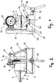
- Fig. 1
- in Vorderansicht eine erfindungsgemäße Entgratvorrichtung,
- Fig. 2
- die Entgratvorrichtung gemäß
Fig. 1 in Seitenansicht, - Fig. 3
- die Einzelheit X in
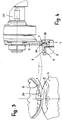
Fig. 1 in vergrößerter Darstellung, - Fig. 4
- in vergrößerter Darstellung und teilweise im Schnitt den Antrieb eines Entgratergehäuses eines erfindungsgemäßen Rohrentgraters,
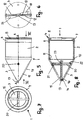
- Fig. 5
- in Seitenansicht und in vergrößerter Darstellung den erfindungsgemäßen Rohrentgrater,
- Fig. 6
- eine Ansicht in Richtung des Pfeiles VI in
Fig. 5 , - Fig. 7
- eine Ansicht in Richtung des Pfeiles VII in
Fig. 5 , - Fig. 8
- einen Schnitt längs der Linie A-A in
Fig. 5 . - Die im Folgenden beschriebene Entgratvorrichtung dient zum Innenentgra-ten von Rohren von Pressfitting-Systemen. Solche Rohre bei Pressfitting-Systemen werden üblicherweise aus nichtrostendem Stahl, Kupfer oder Kunststoff gefertigt. Mit der Entgratvorrichtung werden insbesondere Rohre innenentgratet, die größere Durchmesser haben, beispielsweise im Bereich von 28 bis 108 mm.
- Die Entgratvorrichtung hat einen Rohrentgrater mit einem Entgratergehäuse 1 (
Fig. 1 und5 bis 8 ), das vorteilhaft aus metallischem Werkstoff besteht. Das Entgratergehäuse 1 hat einen zylindrischen Teil 2 und einen Konusteil 3, der an das eine Ende des zylindrischen Teiles 2 anschließt. Im Ausführungsbeispiel sind die beiden Teile 2, 3 getrennte Teile, die fest miteinander verbunden sind, beispielsweise durch Kleben, Löten oder Schweißen. An das andere Ende des zylindrischen Teiles 2 ist ein Reibkranz 4 angeschlossen, der ringförmig ausgebildet ist und radial nach innen über die Innenwand des Zylinderteiles 2 ragt (Fig. 4 und8 ). Der Reibkranz 4 hat einen axialen ringförmigen Vorsprung 5, mit dem er in eine zur Stirnseite hin offene ringförmige Vertiefung 6 in der Außenseite des Zylinderteiles 2 eingreift. Über den ringförmigen Vorsprung 5 wird der Reibkranz 4 fest mit dem zylindrischen Teil 2 verbunden. Der Reibkranz 4 weist in seiner Außenseite 7 eine umlaufende rillenförmige Vertiefung 8 auf, in die ein Schneidrad 9 (Fig. 4 ) eingreift. Das Schneidrad 9 wird in noch zu beschreibender Weise um seine Achse drehbar angetrieben und radial gegen den Reibkranz 4 gedrückt. Infolge der Reibung zwischen dem Schneidrad 9 und dem Reibkranz 4 wird das Entgratergehäuse 1 um seine Achse drehbar angetrieben. - Der Konusteil 3 des Entgratergehäuses 1 hat ebenfalls einen ringförmigen Vorsprung 10, der in eine an der Außenseite des zylindrischen Teiles 2 des Entgratergehäuses 1 vorgesehene umlaufende Vertiefung 11 eingreift. Sie ist wie die Vertiefung 6 zur Stirnseite des zylindrischen Teiles 2 offen. Über den Vorsprung 10 wird der Konusteil 3 fest mit dem zylindrischen Teil 2 verbunden, beispielsweise durch Kleben, Löten, Schweißen oder dergleichen.
- Der Konusteil 3 verjüngt sich vom zylindrischen Teil 2 aus stetig. Der Konusteil 3 ist mit zwei diametral einander gegenüberliegenden Schlitzen 12 versehen (
Fig. 6 ), die sich von einem zentralen Mittelstück 13 am freien Ende des Konusteiles 3 aus bis nahe an den Übergang zum zylindrischen Teil 2 erstrecken. Das Mittelstück 13 schließt den Konusteil 3 ab und ist innenseitig mit einer Aufnahme 14 (Fig. 8 ) für eine Entgraterklinge 15 versehen. Sie hat etwa dreieckförmigen Umriss mit einer abgeschnittenen Dreieckspitze 16, die in die Aufnahme 14 des Mittelstückes 13 ragt. Die Entgraterklinge 15 ist so ausgebildet, dass sie mit einer Dreieckseite 17 durch einen der beiden Schlitze 12 ragt (Fig. 5 ). Dieser vorstehende Teil 17 der Entgraterklinge 15 entfernt den Innengrat am Rohr. Der überstehende Klingenteil 17 erstreckt sich über die gesamte Länge des entsprechenden Schlitzes 12. Die Außenseite des Konusteiles 3 ist im Bereich neben dem Schlitz 12 mit einer Abflachung 18 versehen (Fig. 6 ), so dass die Rohrentgratung zuverlässig durchgeführt werden kann. - Die Entgraterklinge 15 kann auch so ausgebildet sein, dass durch den anderen Schlitz 12 die andere, ein Klingenteil bildende Dreieckseite ragt. Dann ist das Entgratergehäuse 1 mit zwei diametral einander gegenüberliegenden Klingenteilen 17 versehen, deren Schneiden 19 den Grat an der Innenseite des Rohres entfernen.
- Die Entgraterklinge 15 wird durch wenigstens ein Sicherungselement 20, vorzugsweise einen Spannstift, im Konusteil 13 gesichert. Das Sicherungselement 20 ist mit seinen beiden Enden in Aufnahmen 21, 22 befestigt, die an der Innenseite des Konusteils 3 vorgesehen und nach außen offen sind. Damit das Sicherungselement 20 zuverlässig im Konusteil 3 gehalten wird, sind an der Innenseite des Konusteils 3 jeweils zwei Verdickungen vorgesehen, die jeweils von einer Öffnung durchsetzt sind, die zur Außenseite des Konusteiles 3 offen ist und durch die von außen das Sicherungselement 20 eingesetzt werden kann. Die Entgraterklinge 15 ist mit einer Durchtrittsöffnung 23 für das Sicherungselement 20 versehen. Wenn das Sicherungselement 20 in bevorzugter Weise ein Spannstift ist, kann er in den beiden Aufnahmen 21, 22 einwandfrei gehalten werden, so dass die Entgraterklinge 15 einwandfrei gehalten wird. Die beiden Enden des Sicherungselementes 20 liegen vertieft, so dass sie nicht über die Außenseite des Konusteiles 3 überstehen und den Entgratvorgang somit nicht beeinträchtigen können. Die Entgraterklinge 15 wird durch das Sicherungselement 20 mit seiner abgeschnittenen Dreieckspitze in die Aufnahme 14 des Mittelstückes 13 gedrückt. Zudem ist die Entgraterklinge 15 vorteilhaft so ausgebildet, dass sie an der Innenseite des Konusteils 3 abgestützt wird. Dadurch werden unerwünschte Bewegungen der Entgraterklinge 15 relativ zum Konusteil 3 vermieden, so dass ein sauberer Entgratvorgang gewährleistet ist.
- Das Schneidrad 9 ist Teil eines Antriebes 24. Die Entgratervorrichtung hat ein Bett 25 (
Fig. 1 und 2 ), an dessen Oberseite mehrere Auflagerollen 26 bis 29 frei drehbar gelagert sind. Sie haben vorteilhaft gleichen Durchmesser und sind vorteilhaft mit einem Reibbelag versehen. Die Rollen 26 bis 29 sind so angeordnet, dass sie geringfügig über V-förmig zueinander liegende Wände 30, 31 einer V-förmigen Vertiefung 32 vorstehen. Je nach Durchmesser des Entgratergehäuses 1 bzw. seines zylindrischen Teils 2 dienen unterschiedliche Auflagerollen als Auflage für das Entgratergehäuse 1. Wie ausFig. 1 hervorgeht, liegt das Entgratergehäuse 1 mit seinem zylindrischen Teil 2 auf den beiden äußeren Rollen 26, 29 auf. - Die parallel zueinander liegenden Rollen 26 bis 29 sind beispielhaft so angeordnet, dass die beiden äußeren Rollen 26, 29 auf gleicher Höhe liegen, während die inneren Rollen 27, 28 tiefer liegen, jedoch untereinander ebenfalls auf gleicher Höhe angeordnet sind.
- An einer Seite des Bettes 25 ist ein vertikaler Ständer 33 vorgesehen, in dem eine um ihre Achse drehbare vertikale Gewindespindel 34 (
Fig. 2 ) drehbar gelagert ist. Auf ihr sitzt eine (nicht dargestellte) Spindelmutter, die durch Drehen der Gewindespindel 34 nach oben und nach unten bewegt werden kann. Die Gewindemutter ist mit einem Motor/Getriebegehäuse 35 verbunden, in dem ein Getriebe sowie ein Antrieb, vorzugsweise ein Elektromotor, untergebracht sind, um das Schneidrad 9 um seine Achse drehbar anzutreiben. - Um die Gewindespindel 34 zu drehen ist an der dem Ständer 33 gegenüberliegenden Seite des Bettes 25 ein Hebel 36 vorgesehen, der drehfest auf einer Welle 37 sitzt. Sie durchsetzt das Bett 25 nahe seiner Auflageseite senkrecht zu den Rollen 26 bis 29. Über ein Kegelgetriebe ist die Welle 37 mit der Gewindespindel 34 antriebsverbunden. Durch Drehen des Hebels 36 und damit der Welle 37 kann somit die Gewindespindel 34 gedreht werden, um das Schneidrad 9 mit dem Motor/Getriebegehäuse 35 nach oben oder nach unten zu verstellen.
- Mit dem Schneidrad 9 ist es möglich, ein auf den Rollen 26 bis 29 frei aufliegendes Rohr zu durchtrennen, indem das drehende Schneidrad 9 mittels des Hebels 36 gegen das durchzutrennende Rohr verstellt wird. Das angetriebene Schneidrad 9 kommt in Berührung mit dem Rohr, das durch das Schneidrad 9 um seine Achse drehend angetrieben wird. Die Rollen, auf denen das Werkstück jeweils aufliegt, werden durch das drehende Rohr ebenfalls um ihre zueinander parallelen Achsen gedreht. Auf diese Weise wird das Rohr vollständig durchtrennt. Anschließend wird durch entsprechendes Drehen des Hebels 36 das Motor/Getriebegehäuse 35 mit dem Schneidrad 9 nach oben bewegt, bis das Schneidrad 9 oberhalb des durchgetrennten Rohres liegt.
- Nach diesem Trennvorgang ist das Rohr am durchgetrennten Ende innenseitig mit einem ausgeprägten Grat versehen, der nunmehr entfernt wird. Der Rohrentgrater 1 wird auf die entsprechenden Auflagerollen gelegt. Das Schneidrad 9 wird mit Hilfe des Hebels 36 wieder nach unten bewegt, wobei das Schneidrad 9 in die rillenförmige Vertiefung 8 des Entgratergehäuses 1 eingreift (
Fig. 4 ). Die Vertiefung 8 ist so tief und so breit, dass die Umfangsschneide 38 des Schneidrades 9 nicht beschädigt wird, sondern Abstand sowohl von den Seitenwänden als auch vom Boden der Vertiefung 8 hat. Das Schneidrad 9 ist mit einer zylindrischen Mantelfläche 39 versehen, die beim Verstellen des Motor/Getriebegehäuses 35 im Bereich der rillenförmigen Vertiefung 8 zur Anlage an der Außenseite 7 des Reibkranzes 4 gelangt. Mit Hilfe des Hebels 36 kann sehr einfach die Kraft eingestellt werden, mit der die Mantelfläche 39 an der Außenfläche 7 des Reibkranzes 4 des Entgratergehäuses 1 anliegt. Das Entgratergehäuse 1 wird auf diese Weise durch Reibschluss um seine Achse drehbar angetrieben. Die Auflagerollen 26, 29, auf denen das Entgratergehäuse 1 mit seinem zylindrischen Teil 2 aufliegt, sind frei drehbar und gewährleisten außerdem eine einwandfreie Lagesicherung des Entgratergehäuses 1 in Radialrichtung. - Ist das abgetrennte Rohrstück kurz, kann es auch bei großem Durchmesser von Hand noch getragen und gegen den sich drehenden Rohrentgrater gedrückt werden. Die drehende Entgraterklinge 15 entfernt mit der Schneide 19 den innenseitigen Grat des Rohrstückes. Hat das Rohr größere Länge und kann nicht mehr von Hand getragen werden, wird es beispielsweise auf einem höhenverstellbaren Lagerblock abgelegt und von Hand gegen den sich drehenden Rohrentgrater gedrückt. Der Konusteil 3 mit dem Klingenteil 17 steht ausreichend weit über das Bett 25 vor, so dass der Innenentgrat-vorgang problemlos durchgeführt werden kann.
- Aufgrund der beschriebenen Ausbildung des Rohrentgraters kann zum Antrieb sowohl des durchzutrennenden Rohres als auch des Rohrentgraters ein und derselbe Antrieb 24 eingesetzt werden. Dadurch gestalten sich der Trennvorgang sowie der anschließende Entgratvorgang sehr einfach und zeitsparend. Der Rohrentgrater muss lediglich auf die Auflagerollen aufgelegt werden. Der Drehantrieb erfolgt durch das Schneidrad 9 in der beschriebenen Weise, so dass eine zusätzliche Antriebseinheit zum Drehen des Rohrentgraters 1 nicht erforderlich ist.
- Im beschriebenen und dargestellten Ausführungsbeispiel ist der Rohrentgrater ein Innenrohrentgrater. In gleicher Weise ist es möglich, den Rohrentgrater auch als Außenrohrentgrater auszubilden. In diesem Falle wird der zylindrische Teil 2 des Entgratergehäuses 1 verlängert und anstelle des Konusteiles 3 an der Innenseite dieses verlängerten zylindrischen Gehäuseteiles 2 ein Innenkonus ausgebildet. Er verjüngt sich in Richtung auf den zylindrischen Teil 2 und ist innenseitig mit wenigstens einem Innenentgratteil versehen, dessen Entgratschneide auf dem Mantel eines gedachten Konus liegt, der sich in Richtung auf den zylindrischen Teil 2 verjüngt. Der Antrieb eines solchen Außenentgraters erfolgt in gleicher Weise wie beim beschriebenen Innenentgrater. Das Rohr wird in diesem Falle in den verlängerten zylindrischen Teil 2 eingesetzt, wobei die auf dem Konusmantel liegende Entgraterschneide den Außengrat am Rohr entfernt.
- Der Antrieb 24 ist leicht transportierbar und kann somit vom Installateur direkt auf der Baustelle einfach eingesetzt werden. Dabei ist der Antrieb 24 kompakt ausgebildet und erlaubt nicht nur das Durchtrennen von Rohren, sondern auch das Entgraten. Mit der beschriebenen Entgratvorrichtung lassen sich insbesondere Rohre mit großem Durchmesser problemlos entgraten, ohne dass hierzu schwere, baulich große und damit unhandliche Rohrentgrater eingesetzt werden müssen. Bevorzugt wird die Entgratvorrichtung für Rohre von Pressfitting-Systemen eingesetzt, kann aber selbstverständlich auch für andere Rohre verwendet werden.
- Anstelle des Schneidrades 3 kann auch ein übliches Reibrad eingesetzt werden, das mit seiner zylindrischen Mantelfläche an der Außenseite 7 des Reibkranzes 4 unter Druck anliegt. Das drehbar angetriebene Reibrad versetzt infolge des Reibschlusses den Rohrentgrater in Drehung um seine Längsachse. Der Reibkranz 4 muss in diesem Falle keine rillenförmige Vertiefung 8 aufweisen, da das Reibrad nicht mit einer Umfangsschneide wie ein Schneidrad versehen ist. Aber auch wenn der Reibkranz 4 mit der rillenförmigen Vertiefung 8 versehen ist, kann der Rohrentgrater mit Hilfe eines solchen Reibrades ebenfalls zuverlässig in Drehung versetzt werden. Das Reibrad besteht zumindest an seiner zylindrischen Mantelfläche aus einem entsprechenden Reibmaterial, das den hohen Reibschluss mit dem Reibkranz 4 gewährleistet. Der Anpressdruck des Reibrades auf den Reibkranz 4 kann wiederum mit Hilfe des Hebels 36 optimal eingestellt werden, so dass der Rohrentgrater zuverlässig drehbar angetrieben wird. Aufgrund der Höhenverstellbarkeit des Motor/Getriebegehäuses 35 lässt sich das Schneidrad 9 bzw. das Reibrad rasch und einfach auf den Außendurchmesser des Reibkranzes 4 einstellen. Auf den Rollen 26 bis 29 können im Durchmesser unterschiedliche Rohrentgrater aufgelegt werden, je nach Durchmesser des zu entgratenden Rohres.
Claims (13)
- Rohrentgrater, insbesondere für Rohre von Pressfitting-Systemen, mit einem Gehäuse, das über wenigstens einen Teil seiner Länge eine zylindrische Außenseite hat und das mit wenigstens einem Entgratteil versehen ist,
dadurch gekennzeichnet, dass das Gehäuse (1) an seiner zylindrischen Außenseite (7) mit wenigstens einem umlaufenden Reibelement (4) versehen ist. - Rohrentgrater nach Anspruch 1,
dadurch gekennzeichnet, dass das Reibelement (4) ein am Gehäuse (1) befestigter Reibkranz ist. - Rohrentgrater nach Anspruch 1 oder 2,
dadurch gekennzeichnet, dass das Reibelement (4) mit einer umlaufenden Vertiefung (8) versehen ist. - Rohrentgrater nach einem der Ansprüche 1 bis 3,
dadurch gekennzeichnet, dass das Entgratteil (15) eine Entgraterklinge ist, die mit wenigstens einem Klingenteil (17) nach außen über das Gehäuse (1) und/oder nach innen über die Innenseite des Gehäuses (1) ragt. - Rohrentgrater nach einem der Ansprüche 1 bis 4,
dadurch gekennzeichnet, dass das Entgratteil (15) durch wenigstens ein Sicherungselement (20) im Gehäuse (1) befestigt ist. - Entgrateinrichtung mit einem Rohrentgrater nach einem der Ansprüche 1 bis 5,
dadurch gekennzeichnet, dass die Entgrateinrichtung für den Rohrentgrater eine Rollenauflage (26 bis 29) aufweist, die mit wenigstens zwei mit Abstand nebeneinander liegenden, frei drehbaren Rollen versehen ist, auf denen der Rohrentgrater mit seiner zylindrischen Außenseite (7) aufliegt, und dass dem Reibelement (4) des Rohrentgraters wenigstens ein drehbar angetriebenes Reibrad (9) zugeordnet ist, das in Reibeingriff mit dem Reibelement (4) gebracht wird, wodurch der Rohrentgrater auf den Rollen aufliegend um seine Achse drehbar angetrieben wird. - Entgrateinrichtung nach Anspruch 6,
dadurch gekennzeichnet, dass das Reibrad (9) quer zu seiner Drehachse sowie quer zur Drehachse des Rohrentgraters verstellbar ist. - Entgrateinrichtung nach Anspruch 6 oder 7,
dadurch gekennzeichnet, dass das Reibrad (9) längs eines Ständers (33) verstellbar ist. - Entgrateinrichtung nach Anspruch 8,
dadurch gekennzeichnet, dass im Ständer (33) eine Gewindespindel (34) untergebracht ist, auf der eine Spindelmutter sitzt, die mit einem Motor/Getriebegehäuse (35) verbunden ist. - Entgrateinrichtung nach Anspruch 9,
dadurch gekennzeichnet, dass im Motor/Getriebegehäuse (35) ein Motor/Getriebe für das Reibrad (9) vorgesehen ist. - Entgrateinrichtung, insbesondere nach einem der Ansprüche 6 bis 10,
dadurch gekennzeichnet, dass das Reibrad (9) ein Schneidrad zum Durchtrennen des Rohres ist. - Entgrateinrichtung nach Anspruch 11,
dadurch gekennzeichnet, dass das Schneidrad (9) mit einer Umfangsschneide (38) in die umlaufende Vertiefung (8) des Reibelementes (4) eingreift. - Entgrateinrichtung nach einem der Ansprüche 6 bis 12,
dadurch gekennzeichnet, dass der Rohrentgrater und das Reibrad (9) zueinander parallele Drehachsen haben.
Applications Claiming Priority (1)
| Application Number | Priority Date | Filing Date | Title |
|---|---|---|---|
| DE102011014791A DE102011014791A1 (de) | 2011-03-14 | 2011-03-14 | Rohrentgrater, insbesondere für Rohre von Pressfitting-Systemen, sowie Entgrateinrichtung mit einem solchen Rohrentgrater |
Publications (2)
| Publication Number | Publication Date |
|---|---|
| EP2500122A1 true EP2500122A1 (de) | 2012-09-19 |
| EP2500122B1 EP2500122B1 (de) | 2019-04-24 |
Family
ID=45833069
Family Applications (1)
| Application Number | Title | Priority Date | Filing Date |
|---|---|---|---|
| EP12001116.8A Active EP2500122B1 (de) | 2011-03-14 | 2012-02-20 | Rohrentgrater, insbesondere für Rohre von Pressfitting-Systemen, sowie Entgrareinrichtung mit einem solchen Rohrengrater |
Country Status (3)
| Country | Link |
|---|---|
| EP (1) | EP2500122B1 (de) |
| DE (1) | DE102011014791A1 (de) |
| ES (1) | ES2733763T3 (de) |
Cited By (5)
| Publication number | Priority date | Publication date | Assignee | Title |
|---|---|---|---|---|
| CN103008762A (zh) * | 2012-12-31 | 2013-04-03 | 河南六建建筑集团有限公司 | 钢管液压切割机 |
| CN109570628A (zh) * | 2017-09-29 | 2019-04-05 | 上海龙钰电梯配件有限公司 | 一种去除绳轮套管边缘毛刺的装置 |
| CN112916948A (zh) * | 2021-02-26 | 2021-06-08 | 杭州烁林贸易有限公司 | 一种避免摩擦力大造成毛刺多的电动自行车管件切割装置 |
| CN113977004A (zh) * | 2021-11-14 | 2022-01-28 | 申捷科技(苏州)有限公司 | 一种镀锌电线管去毛刺装置及其去毛刺方法 |
| CN115716142A (zh) * | 2022-11-14 | 2023-02-28 | 信尔胜机械(江苏)有限公司 | 一种管状工件自动打孔机 |
Citations (7)
| Publication number | Priority date | Publication date | Assignee | Title |
|---|---|---|---|---|
| US1758521A (en) * | 1927-03-01 | 1930-05-13 | Philip P Kerrigan | Combined pipe-cutting and bur-removing tool |
| US3232145A (en) * | 1963-10-17 | 1966-02-01 | Parker Hannifin Corp | Hand reamer |
| US4229129A (en) * | 1979-03-21 | 1980-10-21 | Schaenzer Gordon N | Chamfer tool |
| JPS606307A (ja) * | 1983-06-24 | 1985-01-14 | Sumitomo Heavy Ind Ltd | 切断・面取り兼用鋸刃を備えた鋼管切断機 |
| US4678380A (en) * | 1986-01-17 | 1987-07-07 | Crawford Fitting Co. | Deburring tool |
| JP2008062313A (ja) * | 2006-09-05 | 2008-03-21 | Mcc Corp | 管材切断装置 |
| EP2058067A1 (de) * | 2007-11-06 | 2009-05-13 | REMS-WERK Christian Föll und Söhne GmbH | Vorrichtung mit einem Antrieb und einem Entgratwerkzeug sowie Entgratwerkzeug |
-
2011
- 2011-03-14 DE DE102011014791A patent/DE102011014791A1/de not_active Withdrawn
-
2012
- 2012-02-20 ES ES12001116T patent/ES2733763T3/es active Active
- 2012-02-20 EP EP12001116.8A patent/EP2500122B1/de active Active
Patent Citations (7)
| Publication number | Priority date | Publication date | Assignee | Title |
|---|---|---|---|---|
| US1758521A (en) * | 1927-03-01 | 1930-05-13 | Philip P Kerrigan | Combined pipe-cutting and bur-removing tool |
| US3232145A (en) * | 1963-10-17 | 1966-02-01 | Parker Hannifin Corp | Hand reamer |
| US4229129A (en) * | 1979-03-21 | 1980-10-21 | Schaenzer Gordon N | Chamfer tool |
| JPS606307A (ja) * | 1983-06-24 | 1985-01-14 | Sumitomo Heavy Ind Ltd | 切断・面取り兼用鋸刃を備えた鋼管切断機 |
| US4678380A (en) * | 1986-01-17 | 1987-07-07 | Crawford Fitting Co. | Deburring tool |
| JP2008062313A (ja) * | 2006-09-05 | 2008-03-21 | Mcc Corp | 管材切断装置 |
| EP2058067A1 (de) * | 2007-11-06 | 2009-05-13 | REMS-WERK Christian Föll und Söhne GmbH | Vorrichtung mit einem Antrieb und einem Entgratwerkzeug sowie Entgratwerkzeug |
Cited By (7)
| Publication number | Priority date | Publication date | Assignee | Title |
|---|---|---|---|---|
| CN103008762A (zh) * | 2012-12-31 | 2013-04-03 | 河南六建建筑集团有限公司 | 钢管液压切割机 |
| CN103008762B (zh) * | 2012-12-31 | 2016-08-31 | 河南六建建筑集团有限公司 | 钢管液压切割机 |
| CN109570628A (zh) * | 2017-09-29 | 2019-04-05 | 上海龙钰电梯配件有限公司 | 一种去除绳轮套管边缘毛刺的装置 |
| CN112916948A (zh) * | 2021-02-26 | 2021-06-08 | 杭州烁林贸易有限公司 | 一种避免摩擦力大造成毛刺多的电动自行车管件切割装置 |
| CN113977004A (zh) * | 2021-11-14 | 2022-01-28 | 申捷科技(苏州)有限公司 | 一种镀锌电线管去毛刺装置及其去毛刺方法 |
| CN115716142A (zh) * | 2022-11-14 | 2023-02-28 | 信尔胜机械(江苏)有限公司 | 一种管状工件自动打孔机 |
| CN115716142B (zh) * | 2022-11-14 | 2023-09-26 | 信尔胜机械(江苏)有限公司 | 一种管状工件自动打孔机 |
Also Published As
| Publication number | Publication date |
|---|---|
| DE102011014791A1 (de) | 2012-09-20 |
| ES2733763T3 (es) | 2019-12-02 |
| EP2500122B1 (de) | 2019-04-24 |
Similar Documents
| Publication | Publication Date | Title |
|---|---|---|
| EP3017909B1 (de) | Verstelleinrichtung mit einer druckrolle einer bearbeitungsmaschine, insbesondere kehlmaschine, sowie bearbeitungsmaschine, insbesondere kehlmaschine, mit einer solchen verstelleinrichtung | |
| EP2788138B1 (de) | Vorrichtung zum ablängen von wellrohren | |
| EP2500122B1 (de) | Rohrentgrater, insbesondere für Rohre von Pressfitting-Systemen, sowie Entgrareinrichtung mit einem solchen Rohrengrater | |
| EP0085770B1 (de) | Vorrichtung zum Einschneiden von Öffnungen in Rohre | |
| DE102019112363A1 (de) | Rohrschneider zum Schneiden eines Rundrohres und Verfahren zum Ablängen eines Rundrohres | |
| EP1459825B1 (de) | Trennvorrichtung für Werkstücke, wie Stangen, Bolzen und dergleichen, insbesondere für Gewindestangen | |
| DE102008021805B4 (de) | Schneid- und Anfasvorrichtung für Rohre | |
| EP0237603B1 (de) | Späneabförderer für Maschinen, die eine spanabhebende Bearbeitung von insbesondere metallischen Werkstücken durchführen | |
| EP1782904B1 (de) | Trennvorrichtung für Werkstücke, wie Rohre, Stangen und dergleichen | |
| DE102016005783B4 (de) | Bearbeitungsvorrichtung für Rohrenden | |
| DE202006002153U1 (de) | Futter- und Tränkvorrichtung für Haustiere | |
| DE102014116388A1 (de) | Rohrschneidevorrichtung und Rohrschneidemaschine mit einer solchen | |
| EP2740556B1 (de) | Trennvorrichtung mit zur Abstützung von Werkstücke, wie Stangen, Rohre und dergleichen, dienenden Rollen | |
| DE102010010894B4 (de) | Stützeinrichtung für Werkstücke, wie Rohre und dergleichen, sowie Trennvorrichtung für solche Werkstücke | |
| DE102013005000B4 (de) | Gerätekopf für ein Werkzeuggerät, insbesondere für eine Ringkreissäge oder einen Winkelschleifer | |
| EP3053680A1 (de) | Verstellbarer anfaskopf für eine rohrendenbearbeitungsstation sowie rohrendenbearbeitungsstation | |
| DE10325375A1 (de) | Trennvorrichtung für Rohre aus Metall | |
| EP2058067A1 (de) | Vorrichtung mit einem Antrieb und einem Entgratwerkzeug sowie Entgratwerkzeug | |
| DE10355144B4 (de) | Rohrtrenngerät für Installationsrohre aus Kunststoff | |
| DE102006006189B3 (de) | Futter- und Tränkvorrichtung für Haustiere | |
| DE102013106545B3 (de) | Fräsvorrichtung mit einem Werkzeugträger | |
| EP2567762A1 (de) | Vorrichtung zum Wellen eines aus Metall bestehenden Rohres | |
| DE102015216720B3 (de) | Werkzeug und Verfahren zum Schälen von Rohren | |
| EP4299202A1 (de) | Bohrmaschinenaufsatz zum bearbeiten von rohrenden | |
| DE102007019893A1 (de) | Rohrtrenngerät und Rohrtrennmaschine |
Legal Events
| Date | Code | Title | Description |
|---|---|---|---|
| PUAI | Public reference made under article 153(3) epc to a published international application that has entered the european phase |
Free format text: ORIGINAL CODE: 0009012 |
|
| AK | Designated contracting states |
Kind code of ref document: A1 Designated state(s): AL AT BE BG CH CY CZ DE DK EE ES FI FR GB GR HR HU IE IS IT LI LT LU LV MC MK MT NL NO PL PT RO RS SE SI SK SM TR |
|
| AX | Request for extension of the european patent |
Extension state: BA ME |
|
| 17P | Request for examination filed |
Effective date: 20130319 |
|
| GRAP | Despatch of communication of intention to grant a patent |
Free format text: ORIGINAL CODE: EPIDOSNIGR1 |
|
| STAA | Information on the status of an ep patent application or granted ep patent |
Free format text: STATUS: GRANT OF PATENT IS INTENDED |
|
| INTG | Intention to grant announced |
Effective date: 20181214 |
|
| GRAS | Grant fee paid |
Free format text: ORIGINAL CODE: EPIDOSNIGR3 |
|
| GRAA | (expected) grant |
Free format text: ORIGINAL CODE: 0009210 |
|
| STAA | Information on the status of an ep patent application or granted ep patent |
Free format text: STATUS: THE PATENT HAS BEEN GRANTED |
|
| RAP1 | Party data changed (applicant data changed or rights of an application transferred) |
Owner name: REMS GMBH & CO KG |
|
| AK | Designated contracting states |
Kind code of ref document: B1 Designated state(s): AL AT BE BG CH CY CZ DE DK EE ES FI FR GB GR HR HU IE IS IT LI LT LU LV MC MK MT NL NO PL PT RO RS SE SI SK SM TR |
|
| REG | Reference to a national code |
Ref country code: GB Ref legal event code: FG4D Free format text: NOT ENGLISH |
|
| REG | Reference to a national code |
Ref country code: CH Ref legal event code: EP |
|
| REG | Reference to a national code |
Ref country code: DE Ref legal event code: R096 Ref document number: 502012014642 Country of ref document: DE |
|
| REG | Reference to a national code |
Ref country code: AT Ref legal event code: REF Ref document number: 1123542 Country of ref document: AT Kind code of ref document: T Effective date: 20190515 Ref country code: IE Ref legal event code: FG4D Free format text: LANGUAGE OF EP DOCUMENT: GERMAN |
|
| REG | Reference to a national code |
Ref country code: NL Ref legal event code: MP Effective date: 20190424 |
|
| REG | Reference to a national code |
Ref country code: LT Ref legal event code: MG4D |
|
| PG25 | Lapsed in a contracting state [announced via postgrant information from national office to epo] |
Ref country code: NL Free format text: LAPSE BECAUSE OF FAILURE TO SUBMIT A TRANSLATION OF THE DESCRIPTION OR TO PAY THE FEE WITHIN THE PRESCRIBED TIME-LIMIT Effective date: 20190424 |
|
| PG25 | Lapsed in a contracting state [announced via postgrant information from national office to epo] |
Ref country code: FI Free format text: LAPSE BECAUSE OF FAILURE TO SUBMIT A TRANSLATION OF THE DESCRIPTION OR TO PAY THE FEE WITHIN THE PRESCRIBED TIME-LIMIT Effective date: 20190424 Ref country code: NO Free format text: LAPSE BECAUSE OF FAILURE TO SUBMIT A TRANSLATION OF THE DESCRIPTION OR TO PAY THE FEE WITHIN THE PRESCRIBED TIME-LIMIT Effective date: 20190724 Ref country code: HR Free format text: LAPSE BECAUSE OF FAILURE TO SUBMIT A TRANSLATION OF THE DESCRIPTION OR TO PAY THE FEE WITHIN THE PRESCRIBED TIME-LIMIT Effective date: 20190424 Ref country code: LT Free format text: LAPSE BECAUSE OF FAILURE TO SUBMIT A TRANSLATION OF THE DESCRIPTION OR TO PAY THE FEE WITHIN THE PRESCRIBED TIME-LIMIT Effective date: 20190424 Ref country code: PT Free format text: LAPSE BECAUSE OF FAILURE TO SUBMIT A TRANSLATION OF THE DESCRIPTION OR TO PAY THE FEE WITHIN THE PRESCRIBED TIME-LIMIT Effective date: 20190824 Ref country code: SE Free format text: LAPSE BECAUSE OF FAILURE TO SUBMIT A TRANSLATION OF THE DESCRIPTION OR TO PAY THE FEE WITHIN THE PRESCRIBED TIME-LIMIT Effective date: 20190424 Ref country code: AL Free format text: LAPSE BECAUSE OF FAILURE TO SUBMIT A TRANSLATION OF THE DESCRIPTION OR TO PAY THE FEE WITHIN THE PRESCRIBED TIME-LIMIT Effective date: 20190424 |
|
| PG25 | Lapsed in a contracting state [announced via postgrant information from national office to epo] |
Ref country code: LV Free format text: LAPSE BECAUSE OF FAILURE TO SUBMIT A TRANSLATION OF THE DESCRIPTION OR TO PAY THE FEE WITHIN THE PRESCRIBED TIME-LIMIT Effective date: 20190424 Ref country code: PL Free format text: LAPSE BECAUSE OF FAILURE TO SUBMIT A TRANSLATION OF THE DESCRIPTION OR TO PAY THE FEE WITHIN THE PRESCRIBED TIME-LIMIT Effective date: 20190424 Ref country code: RS Free format text: LAPSE BECAUSE OF FAILURE TO SUBMIT A TRANSLATION OF THE DESCRIPTION OR TO PAY THE FEE WITHIN THE PRESCRIBED TIME-LIMIT Effective date: 20190424 Ref country code: BG Free format text: LAPSE BECAUSE OF FAILURE TO SUBMIT A TRANSLATION OF THE DESCRIPTION OR TO PAY THE FEE WITHIN THE PRESCRIBED TIME-LIMIT Effective date: 20190724 |
|
| REG | Reference to a national code |
Ref country code: ES Ref legal event code: FG2A Ref document number: 2733763 Country of ref document: ES Kind code of ref document: T3 Effective date: 20191202 |
|
| PG25 | Lapsed in a contracting state [announced via postgrant information from national office to epo] |
Ref country code: IS Free format text: LAPSE BECAUSE OF FAILURE TO SUBMIT A TRANSLATION OF THE DESCRIPTION OR TO PAY THE FEE WITHIN THE PRESCRIBED TIME-LIMIT Effective date: 20190824 |
|
| REG | Reference to a national code |
Ref country code: DE Ref legal event code: R097 Ref document number: 502012014642 Country of ref document: DE |
|
| PG25 | Lapsed in a contracting state [announced via postgrant information from national office to epo] |
Ref country code: SK Free format text: LAPSE BECAUSE OF FAILURE TO SUBMIT A TRANSLATION OF THE DESCRIPTION OR TO PAY THE FEE WITHIN THE PRESCRIBED TIME-LIMIT Effective date: 20190424 Ref country code: CZ Free format text: LAPSE BECAUSE OF FAILURE TO SUBMIT A TRANSLATION OF THE DESCRIPTION OR TO PAY THE FEE WITHIN THE PRESCRIBED TIME-LIMIT Effective date: 20190424 Ref country code: RO Free format text: LAPSE BECAUSE OF FAILURE TO SUBMIT A TRANSLATION OF THE DESCRIPTION OR TO PAY THE FEE WITHIN THE PRESCRIBED TIME-LIMIT Effective date: 20190424 Ref country code: EE Free format text: LAPSE BECAUSE OF FAILURE TO SUBMIT A TRANSLATION OF THE DESCRIPTION OR TO PAY THE FEE WITHIN THE PRESCRIBED TIME-LIMIT Effective date: 20190424 Ref country code: DK Free format text: LAPSE BECAUSE OF FAILURE TO SUBMIT A TRANSLATION OF THE DESCRIPTION OR TO PAY THE FEE WITHIN THE PRESCRIBED TIME-LIMIT Effective date: 20190424 |
|
| PG25 | Lapsed in a contracting state [announced via postgrant information from national office to epo] |
Ref country code: SM Free format text: LAPSE BECAUSE OF FAILURE TO SUBMIT A TRANSLATION OF THE DESCRIPTION OR TO PAY THE FEE WITHIN THE PRESCRIBED TIME-LIMIT Effective date: 20190424 |
|
| PLBE | No opposition filed within time limit |
Free format text: ORIGINAL CODE: 0009261 |
|
| STAA | Information on the status of an ep patent application or granted ep patent |
Free format text: STATUS: NO OPPOSITION FILED WITHIN TIME LIMIT |
|
| PG25 | Lapsed in a contracting state [announced via postgrant information from national office to epo] |
Ref country code: TR Free format text: LAPSE BECAUSE OF FAILURE TO SUBMIT A TRANSLATION OF THE DESCRIPTION OR TO PAY THE FEE WITHIN THE PRESCRIBED TIME-LIMIT Effective date: 20190424 |
|
| 26N | No opposition filed |
Effective date: 20200127 |
|
| PG25 | Lapsed in a contracting state [announced via postgrant information from national office to epo] |
Ref country code: SI Free format text: LAPSE BECAUSE OF FAILURE TO SUBMIT A TRANSLATION OF THE DESCRIPTION OR TO PAY THE FEE WITHIN THE PRESCRIBED TIME-LIMIT Effective date: 20190424 |
|
| REG | Reference to a national code |
Ref country code: CH Ref legal event code: PL |
|
| GBPC | Gb: european patent ceased through non-payment of renewal fee |
Effective date: 20200220 |
|
| REG | Reference to a national code |
Ref country code: BE Ref legal event code: MM Effective date: 20200229 |
|
| PG25 | Lapsed in a contracting state [announced via postgrant information from national office to epo] |
Ref country code: MC Free format text: LAPSE BECAUSE OF FAILURE TO SUBMIT A TRANSLATION OF THE DESCRIPTION OR TO PAY THE FEE WITHIN THE PRESCRIBED TIME-LIMIT Effective date: 20190424 Ref country code: LU Free format text: LAPSE BECAUSE OF NON-PAYMENT OF DUE FEES Effective date: 20200220 |
|
| PG25 | Lapsed in a contracting state [announced via postgrant information from national office to epo] |
Ref country code: LI Free format text: LAPSE BECAUSE OF NON-PAYMENT OF DUE FEES Effective date: 20200229 Ref country code: CH Free format text: LAPSE BECAUSE OF NON-PAYMENT OF DUE FEES Effective date: 20200229 |
|
| PG25 | Lapsed in a contracting state [announced via postgrant information from national office to epo] |
Ref country code: GB Free format text: LAPSE BECAUSE OF NON-PAYMENT OF DUE FEES Effective date: 20200220 Ref country code: IE Free format text: LAPSE BECAUSE OF NON-PAYMENT OF DUE FEES Effective date: 20200220 |
|
| PG25 | Lapsed in a contracting state [announced via postgrant information from national office to epo] |
Ref country code: BE Free format text: LAPSE BECAUSE OF NON-PAYMENT OF DUE FEES Effective date: 20200229 |
|
| REG | Reference to a national code |
Ref country code: AT Ref legal event code: MM01 Ref document number: 1123542 Country of ref document: AT Kind code of ref document: T Effective date: 20200220 |
|
| PG25 | Lapsed in a contracting state [announced via postgrant information from national office to epo] |
Ref country code: AT Free format text: LAPSE BECAUSE OF NON-PAYMENT OF DUE FEES Effective date: 20200220 |
|
| PG25 | Lapsed in a contracting state [announced via postgrant information from national office to epo] |
Ref country code: MT Free format text: LAPSE BECAUSE OF FAILURE TO SUBMIT A TRANSLATION OF THE DESCRIPTION OR TO PAY THE FEE WITHIN THE PRESCRIBED TIME-LIMIT Effective date: 20190424 Ref country code: CY Free format text: LAPSE BECAUSE OF FAILURE TO SUBMIT A TRANSLATION OF THE DESCRIPTION OR TO PAY THE FEE WITHIN THE PRESCRIBED TIME-LIMIT Effective date: 20190424 |
|
| PG25 | Lapsed in a contracting state [announced via postgrant information from national office to epo] |
Ref country code: MK Free format text: LAPSE BECAUSE OF FAILURE TO SUBMIT A TRANSLATION OF THE DESCRIPTION OR TO PAY THE FEE WITHIN THE PRESCRIBED TIME-LIMIT Effective date: 20190424 |
|
| PG25 | Lapsed in a contracting state [announced via postgrant information from national office to epo] |
Ref country code: GR Free format text: LAPSE BECAUSE OF FAILURE TO SUBMIT A TRANSLATION OF THE DESCRIPTION OR TO PAY THE FEE WITHIN THE PRESCRIBED TIME-LIMIT Effective date: 20190424 |
|
| PGFP | Annual fee paid to national office [announced via postgrant information from national office to epo] |
Ref country code: IT Payment date: 20230206 Year of fee payment: 12 |
|
| PGFP | Annual fee paid to national office [announced via postgrant information from national office to epo] |
Ref country code: DE Payment date: 20230426 Year of fee payment: 12 |
|
| P01 | Opt-out of the competence of the unified patent court (upc) registered |
Effective date: 20231115 |
|
| PGFP | Annual fee paid to national office [announced via postgrant information from national office to epo] |
Ref country code: FR Payment date: 20231212 Year of fee payment: 13 |
|
| PGFP | Annual fee paid to national office [announced via postgrant information from national office to epo] |
Ref country code: ES Payment date: 20240305 Year of fee payment: 13 |