EP2500107A1 - Df-beschichter - Google Patents
Df-beschichter Download PDFInfo
- Publication number
- EP2500107A1 EP2500107A1 EP09851247A EP09851247A EP2500107A1 EP 2500107 A1 EP2500107 A1 EP 2500107A1 EP 09851247 A EP09851247 A EP 09851247A EP 09851247 A EP09851247 A EP 09851247A EP 2500107 A1 EP2500107 A1 EP 2500107A1
- Authority
- EP
- European Patent Office
- Prior art keywords
- coating material
- material chamber
- diluent
- coater
- coating
- Prior art date
- Legal status (The legal status is an assumption and is not a legal conclusion. Google has not performed a legal analysis and makes no representation as to the accuracy of the status listed.)
- Withdrawn
Links
Images


Classifications
-
- B—PERFORMING OPERATIONS; TRANSPORTING
- B05—SPRAYING OR ATOMISING IN GENERAL; APPLYING FLUENT MATERIALS TO SURFACES, IN GENERAL
- B05C—APPARATUS FOR APPLYING FLUENT MATERIALS TO SURFACES, IN GENERAL
- B05C5/00—Apparatus in which liquid or other fluent material is projected, poured or allowed to flow on to the surface of the work
- B05C5/02—Apparatus in which liquid or other fluent material is projected, poured or allowed to flow on to the surface of the work the liquid or other fluent material being discharged through an outlet orifice by pressure, e.g. from an outlet device in contact or almost in contact, with the work
- B05C5/0254—Coating heads with slot-shaped outlet
- B05C5/0262—Coating heads with slot-shaped outlet adjustable in width, i.e. having lips movable relative to each other in order to modify the slot width, e.g. to close it
-
- B—PERFORMING OPERATIONS; TRANSPORTING
- B05—SPRAYING OR ATOMISING IN GENERAL; APPLYING FLUENT MATERIALS TO SURFACES, IN GENERAL
- B05C—APPARATUS FOR APPLYING FLUENT MATERIALS TO SURFACES, IN GENERAL
- B05C5/00—Apparatus in which liquid or other fluent material is projected, poured or allowed to flow on to the surface of the work
- B05C5/005—Curtain coaters
-
- D—TEXTILES; PAPER
- D21—PAPER-MAKING; PRODUCTION OF CELLULOSE
- D21H—PULP COMPOSITIONS; PREPARATION THEREOF NOT COVERED BY SUBCLASSES D21C OR D21D; IMPREGNATING OR COATING OF PAPER; TREATMENT OF FINISHED PAPER NOT COVERED BY CLASS B31 OR SUBCLASS D21G; PAPER NOT OTHERWISE PROVIDED FOR
- D21H23/00—Processes or apparatus for adding material to the pulp or to the paper
- D21H23/02—Processes or apparatus for adding material to the pulp or to the paper characterised by the manner in which substances are added
- D21H23/22—Addition to the formed paper
- D21H23/46—Pouring or allowing the fluid to flow in a continuous stream on to the surface, the entire stream being carried away by the paper
Definitions
- the present invention relates to a direct fountain coater for applying a coating material to a substrate by allowing the coating material to fall in a curtain-like manner.
- a direct fountain coater also known as curtain coater
- the DF coater guides a deaerated coating material, which is supplied to a DF coater head, to a nozzle portion at a lower part smoothly and without causing retention, and forms a coating liquid curtain having a uniform and stable flow rate by adjusting a flow of the coating material to be uniform in the width direction by means of the nozzle portion and allowing it to flow out from a nozzle tip.
- the coating liquid curtain is applied uniformly onto the substrate by being stretched at the same speed as the substrate at an instant of impingement to the substrate (see for example Japanese Laid-Open Patent Application No. 2000-210607 ).
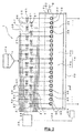
- Fig. 6 is a cross-sectional view of a DF coater head of the related art.
- a DF coater head 50 is formed in an elongated manner across a width direction of a substrate 51 (a direction perpendicular to the plane of paper of Fig. 6 ) and is provided with a coating material chamber 52 therein which extends along a longitudinal direction thereof.
- a deaerated coating material 53 is injected through a coating material injecting port (not shown), which is located at an end portion in the longitudinal-direction of the DF coater head, and supplied into the chamber.
- a nozzle portion 54 that allows the coating material to fall in a curtain-like manner is formed at a lower side of the coating material chamber 52.
- the nozzle portion 54 is configured in such a manner that a slit-like gap is adjustable by moving a lip portion 55 that extends along the width direction.
- the lip portion 55 is pushed and pulled by a plurality of stepping motors 56 provided at intervals along the width direction (a differential screw 57 is provided along an axis of rotation of the stepping motor 56 and a lower portion of the lip portion 55 is moved in a right-left direction in the plane of paper of Fig. 6 by the differential screw 57. See Fig. 6 for the lip portion 55 shown by a solid line (before movement) and a double dot dash line (after movement)), so as to adjust the gap in the nozzle portion 54.
- the aforementioned coating material chamber is configured to extend along a longitudinal direction, a difference in the flow rate of the coating material may arise throughout the longitudinal direction.
- a thickness (the flow rate) of the coating liquid curtain falling from the nozzle portion will not be uniform and there will be a density variation (unevenness) in a coated surface of the substrate, and thus a well-coated surface cannot be obtained.
- a large difference in the flow rate produced locally may cause a split in the coating liquid curtain.
- one or more of the aforementioned plurality of stepping motors are operated, and the gap in the width direction is partially adjusted by pushing and pulling the lip portion.
- the flow rate of the coating material falling from the nozzle portion 54 is partially adjusted and the thickness (flow rate) of the curtain of coating material is adjusted to become uniform.
- the density variation is prevented from being produced in the coated surface of the substrate.
- An object of the present invention is to provide a DF coater which can suppress an occurrence of the density variation or unevenness in the coated surface of the substrate without adjusting the thickness of the coating liquid curtain.
- a direct fountain coater includes a DF coater head formed in an elongated manner along a width direction of a substrate to be coated, the DF coater head having a coating material chamber formed therein which extends along a longitudinal direction thereof, a coating material for coating being supplied into the coating material chamber, wherein the DF coater head includes a plurality of supply ports disposed at intervals along the longitudinal direction and providing communication between an outer side of the DF coater head and an inner side of the coating material chamber, the plurality of supply ports being configured to supply, into the coating material chamber, a diluent that dilutes a density of the coating material retained in the coating material chamber.
- each of the plurality of supply ports or a duct connected to each of the plurality of supply ports may be provided with a valve which can adjust a supply amount of the diluent.
- each of the plurality of supply ports may be formed in a slit shape elongated along the longitudinal direction.
- each of the plurality of supply ports may be formed in a flat surface portion outside the DF coater head and in the vicinity of the coating material chamber.
- valve may be capable of adjusting the supply amount of the diluent at each of the supply ports.
- each of the valves may be a control valve that operates in accordance with a signal from a control unit.
- a scanner that detects one of a coat thickness and a coating amount in a width direction of a coated substrate may be provided, wherein the control unit performs a feedback control for each of the control valves based on information sent from the scanner.
- the DF coater head since the DF coater head includes a plurality of supply ports disposed at intervals along the longitudinal direction and providing communication between an outer side of the DF coater head and an inner side of the coating material chamber, the supply ports being configured to supply, into the coating material chamber, a diluent that dilutes a density of the coating material retained in the coating material chamber, concentration of the coating material at a portion where the flow rate is high in the coating material chamber can be reduced by supplying a diluent at a portion where the flow rate of the coating material is high.
- a substantive amount of the coating material coated on the substrate (the actual coating material that remains on the coating surface after having evaporated the moisture by drying the coated substrate) can be made substantially uniform by diluting, with the diluent, the portion where the thickness of the coating liquid curtain is thick and the portion where the flow speed is high. Therefore, after the drying of the substrate, the amount of the coating material remaining on the substrate will be substantially uniform, and an occurrence of the density variation or unevenness in the coated surface can be suppressed. Therefore, without having to adjust the thickness of the coating liquid curtain by pushing and pulling a lip portion, an occurrence of the density variation or unevenness in the coated surface of the substrate can be suppressed.
- Fig. 1 is a schematic view illustrating a DF coater 1 of the aspect of the present invention.
- the DF coater 1 includes a supply tank 10 that supplies a coating material 2 into a system of the DF coater 1, a deaerator 12 disposed downstream of the supply tank 10 and removes air bubbles produced in the coating material 2, and a DF coater head 14 disposed downstream of the deaerator 12.
- the coating material 2 in the supply tank 10 is delivered to the deaerator 12 by a first circulation pump 11.
- the coating material 2 that has been deaerated in the deaerator 12 is delivered to the DF coater head 14 by a second circulation pump 13.
- the DF coater 1 includes a return tank 16 that is situated downstream of the DF coater head 14 and reserves the coating material 2 which has fallen from the DF coater head 14 and thereafter collected by the drain pan 15.
- the coating material 2 in the return tank 16 is returned to the aforementioned supply tank 10 by a third circulation pump 17.
- the DF coater 1 includes a diluent tank 18 whereto a diluent 3 to be delivered to the DF coater head 14 is supplied, a plurality of control valves 21 disposed in ducts 20 connecting the diluent tank 18 and the DF coater head 14, a control unit 22 for controlling the control valves 21, and a scanner 23 situated on a downstream side in a direction of travel of a substrate delivered for a coating process (situated downstream of the DF coater head 14) and detects a thickness and a basis weight (or, an coating amount) of a coat in a width direction of the substrate after being coated on the substrate.
- the diluent 3 in the diluent tank 18 is delivered to the DF coater head 14 by a fourth circulation pump 19.
- the scanner 23 is electrically connected to the control unit 22 via a wiring 25 and is capable of sending information detected with the scanner 23 to the control unit 22.
- the control unit 22 is electrically connected to the plurality of control valves 21 via respective wirings 24, and the respective control valves 21 are individually controlled to open and close based on a flow rate adjustment signal sent from the control unit 22.
- the aforementioned control valve 21 can adjust the flow rate of the diluent 3 by opening and closing a valve in accordance with a control signal, and, for example, may be an electromagnetically-operated open/close valve or a motor-operated open/close valve. Also, a pinch valve that adjusts the flow rate by pressing a rubber tube may be used to adjust a small amount of flow rate.
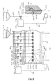
- Fig. 2 is a simplified schematic view illustrating a structure of supplying the diluent 3 to the DF coater head 14, and Fig. 3 is a cross-sectional view taken along line A-A in the DF coater head 14 illustrated in Fig. 2 .
- the DF coater head 14 is formed in an elongated manner along a right-left direction in the plane of paper (a width direction of the substrate that is being delivered, i.e., the substrate is fed from a front side of the plane of paper into a rear side of the plane of paper) and its length is greater than a width-direction length of the substrate.
- the DF coater head 14 is constituted by assembling two members (members 14a and 14b).
- the member 14b has a groove portion extending in a longitudinal direction and formed in a surface which comes into contact with the member 14a, and in a state where the members 14a and 14b are assembled (a state shown in Fig. 3 ), the groove portion is closed and forms a coating material chamber 31.
- the coating material 2 is injected through a coating material inlet 32 provided at an end portion on right hand side in the plane of paper in the longitudinal direction.
- the coating material 2 deaerated in the aforementioned deaerator 12 see Fig. 1
- the second circulation pump 13 is injected. It is to be noted that both end portions of the coating material chamber 31 are closed with respective closing members, not shown, so that the coating material 2 does not leak.
- a gap extending downwardly from the coating material chamber 31 is formed in the DF coater head 14, and a nozzle portion 33 is constituted by this gap.
- the nozzle portion 33 is formed as a slit that continues along the longitudinal direction in the same manner as the coating material chamber 31.
- the DF coater head 14 is formed in such a manner that a plurality of supply ports 30 that are formed in the member 14a and communicate from an outer side of the member 14a to an inside of the coating material chamber 31 are lying in a substantially horizontal direction.
- the supply ports 30 are formed at substantially equal intervals (in the present aspect, at a pitch of approximately 50 mm) linearly along the longitudinal direction.
- respective openings of the supply ports 30 are located in an outer flat surface portion of the member 14a and in the vicinity of the coating material chamber 31.
- the supply ports 30 need not be arranged linearly, but may be provided in a staggered manner in the vertical direction so as to correspond to a shape of a flat surface portion on an outer side of the member 14a. However, in the width direction of the DF coater head 14, it is necessary to arrange at a substantially equal interval.
- the supply ports 30 are formed so as to lie along the horizontal direction, but may lie along the vertical direction as long as processing can be easily performed in such a direction.
- the ducts 20 branching from and connected to the diluent tank 18 are connected to the plurality of supply ports 30 via the control valves 21, respectively. It is to be noted that the supply ports 30 and the ducts 20 are respectively connected via connecting nuts, not shown, providing a watertight structure in which the diluent 3 does not leak from the supply ports 30.
- control unit 22 and the control valves 21 corresponding to the respective supply ports 30 are wired by the wirings 24, respectively, so as to individually control open/close operations of the respective control valves 21 by the control unit 22.
- the diluent 3 can be supplied into the coating material chamber 31 individually, or the flow rate can be adjusted.
- these supply ports 30 are each formed in a circular shape. This shape is to facilitate the processing of the supply port 30 by a drill or the like, and to facilitate a process of forming an internal threading for attaching the aforementioned connecting nut.
- the aforementioned diluent 3 is capable of changing a coating amount on a coated surface after the drying by changing a concentration of the coating material 2, and, for example, water or a low-concentration coating material (the concentration of the coating material 2 is decreased) may be used.
- a coating material of a concentration that is a little lower than that of the coating material 2 is used as the diluent 3.
- a low-concentration coating material is used as the diluent
- water 103 is supplied to the diluent tank 18, and a duct 120, a pump 113 and a static mixer 125 for branching off and drawing in the coating material 3 flowing between the deaerator 12 and the DF coater head 14 into the duct 20 are provided.
- the pump 113 provides a function of delivering the coating material 3 into the static mixer 125
- the static mixer 125 provides a function of mixing the water 103 and the coating material 3 delivered from the diluent tank 18 via the fourth circulation pump 19 and sending out to the duct 21.
- a valve 130 (which may be a manual-type or a controlled type) may be provided upstream of the pump 113 to adjust a flow-in rate of the coating material 2 and to adjust the concentration of the diluent.
- a substrate before being subjected to a coating process and wound up in a roll (reference numeral 51 in Fig. 6 ) is unwound by an unwinding apparatus (not shown), and then wound up in a roll again by a winding apparatus (not shown). During this, the unwound substrate passes through the coating liquid curtain while traveling at a high speed below the DF coater head 14, and a surface of the substrate is coated.
- the coating material 2 is supplied to the supply tank 10 (see Fig. 1 ), and after having removed the air bubbles from the coating material 2 with the deaerator 12 (see Fig. 1 ), the deaerated coating material 2 is delivered to the coating material chamber 31 in the DF coater head 14.
- the coating material 2 is injected through the coating material inlet 32 at the end portion in the longitudinal direction of the coating material chamber 31 (see Fig. 2 ).
- a difference in the flow rate occurs in the coating material 2 in the coating material chamber 31 at each position in the longitudinal direction of the coating material chamber 31 (for example, the flow rate is higher at the end portion of the coating material chamber 31 at which the coating material 2 is injected, and the flow rate decreases as a distance from the end portion becomes greater).
- an irregularity may be produced in the shape of the coating liquid curtain due to the difference in the flow rate (for example, a thickness of the coating liquid curtain directly beneath a portion of greater flow rate is thick and a thickness of the coating liquid curtain directly beneath a portion of less flow rate is thin).
- a coating-unevenness or a density variation may be produced in the coated surface of the substrate surface (for example, a color of a portion with a higher flow rate is dark and a color of a portion with a lower flow rate is pale).
- the concentration of the coating material at a portion where the flow rate is high is reduced by supplying the diluent 3 into the coating material chamber 31 through the supply port 30 at the portion where the flow rate is high.
- a coating material is diluted with the diluent 3.
- the substantive amount of coating material that is coated on the substrate is reduced. Therefore, it becomes approximately the same amount (uniform) as the substantive amount of coating material at a portion where the flow rate is low. Therefore, the coating amount on the entire coated surface after having been dried in the dry chamber can be adjusted to be uniform.
- a method of supplying the diluent 3 can be performed by a manual operation or supplying can be performed by opening and closing the control valve 21 based on a control signal from the control unit 22.
- a determination of the portion where the flow rate is high i.e., the supply port 30 that requires the diluent 3 to be supplied, can be performed by measuring the flow rate per unit time for each pitch (each position of the supply port 30) by means of the flow rate meter or the like which is not shown, obtaining a flow rate profile in the width direction of the substrate, and determining the best supply position by repeating the adjustment and measurement based on the profile.
- the supply position of the diluent 3 can be determined based on an empirical knowledge or determined based on a detection signal from the scanner 23.
- the case of empirical knowledge means a case in which the portion where the flow rate is high can be empirically obtained in advance based on, for example, a length in the longitudinal direction of the coating material chamber 31, a type of coating material 2 supplied into the coating material chamber 31, and the like.
- the supply port 30 whereto the diluent 3 is to be supplied can be determined without using the control unit 22 or the scanner 23.
- the operator may supply the diluent 3 with a manual operation.
- the information empirically obtained in advance may be used to create a program and the control valves 21 can be automatically opened and closed by being controlled using a CPU in the control unit 22.
- a feed back control using the scanner 23 or the control unit 22 can be performed.
- the film thickness or the coating amount (or basis weight) of the coating film coated on the surface of the substrate can be detected in the width direction of the substrate (the longitudinal direction of the DF coater head 14) and the supply port 30 corresponding to the uneven portion can be determined. Accordingly, based on the condition of the coating film, etc., on the surface of the substrate, the feedback control of the opening and closing of the supply port 30 can be performed.
- the DF coater head 14 includes a plurality of supply ports 30 disposed at intervals along the longitudinal direction and providing communication between an outer side of the DF coater head 14 and an inner side of the coating material chamber 31, the supply ports 30 being configured to supply, into the coating material chamber 31, a diluent 3 that dilutes a density of the coating material 2 retained in the coating material chamber 31, the concentration of the coating material 2 at the portion where the flow rate is high in the coating material chamber 13 can be reduced by supplying the diluent 3 at the portion where the flow rate of the coating material 2 is high.
- the substantive amount of coating material coated on the substrate can be made substantially uniform (the actual coating material that remains on the coating surface after having evaporated the moisture by drying the coated substrate) can be reduced. Therefore, after having dried the substrate, the coating material remaining on the substrate is substantially uniform and thus an occurrence of the density variation or unevenness in the coated surface can be suppressed. Therefore, without having to adjust the thickness of the coating liquid curtain by pushing and pulling a lip portion 55 (see Fig. 6 ), an occurrence of the density variation or unevenness in the coated surface of the substrate can be suppressed.
- the ducts 20 connected to the supply ports 30 are provide with control valves 21, respectively, that can adjust a supply amount of the diluent 3 based on the signal from the control unit 22, the diluent 3 can be appropriately supplied at the portion in the coating material chamber 31 where the flow rate of the coating material 2 is high. Thereby, without adjusting the thickness of the coating liquid curtain, an occurrence of the density variation or unevenness in the coated surface of the substrate can be suppressed.
- each of the supply ports 30 is formed in a flat surface portion outside the DF coater head 14 and in the vicinity of the coating material chamber 31, the processing of the supply ports 30 can be performed in a facilitated manner. Also, since they are formed in the vicinity of the coating material chamber 31, respectively, the supply ports 30 can be fabricated so as to communicate from the flat surface portion to the coating material chamber 31 in a facilitated manner.
- the control unit 22 performs a feedback control of each of the control valves 21 based on information sent from the scanner 23, even if an unevenness (irregularity) is produced in the surface of the coating liquid curtain, the unevenness can be automatically corrected by the control unit 22. As a result, occurrence of the density variation or unevenness on a coating surface of an substrate can be suppressed without adjusting the thickness of the coating liquid curtain.
- the direct fountain coater 1 (DF coater or as curtain coater drawable) of the present aspect has been described above, but the present invention is not limited to the aforementioned aspect and rather various variants and modifications are conceivable based on the technical idea of the present invention.
- the supply port 30 has a circular shape, but, as shown in Figs. 4A and 4B, the shape of the supply port 300 may be an elongated hole 301 (slot-like elongated hole).
- the supply port 300 may be configured such that a portion whereto the connecting nut (not shown) is attached is formed as a circular hole and a hole on a side facing the coating material chamber 31 is formed as an elongated hole 301.
- This elongated hole 301 is formed in such a manner that its major axis direction substantially coincides with the longitudinal direction of the DF coater head 14, and its shape may be an elliptic shape or may be a rectangular shape having a longitudinal direction.
- the diluent 3 supplied to the supply port 300 when delivered into the coating material chamber 31, the diluent 3 supplied to the supply port 300 will be supplied in such a manner that it spreads in the longitudinal direction of the DF coater head 140 (constituted by members 140a and 140b) in accordance with the shape of the elongated hole 301, and the concentration of the coating material 2 in a large region can be diluted for the coating material 2 reserved in the coating material chamber 31. Also, by employing the elongated hole shape, a distance between the neighboring elongated holes becomes shorter and a region in which the diluent 3 is supplied can be enlarged. Further, it is will not be necessary to reduce the pitch of the supply ports 300 more than required.
- control valves 21 are provided in the ducts 20 connecting the diluent tank 18 and the plurality of supply ports 30 and controlled, manually-adjustable open/close valves may be employed. In such a case, the operator checks the condition of the coating film or the like which is coated on the substrate, determines through which supply port 30 in the width direction of the substrate the diluent 3 is to be supplied, and manually opens and closes the valves at such a portion.
- a ratio of coating material 100%: diluent 0% is taken as a basis, and only an adjustment by diluting the portion where the flow rate is high is performed.
Landscapes
- Coating Apparatus (AREA)
- Paper (AREA)
Applications Claiming Priority (1)
| Application Number | Priority Date | Filing Date | Title |
|---|---|---|---|
| PCT/JP2009/006091 WO2011058613A1 (ja) | 2009-11-13 | 2009-11-13 | Dfコータ |
Publications (2)
| Publication Number | Publication Date |
|---|---|
| EP2500107A1 true EP2500107A1 (de) | 2012-09-19 |
| EP2500107A4 EP2500107A4 (de) | 2014-06-11 |
Family
ID=43991293
Family Applications (1)
| Application Number | Title | Priority Date | Filing Date |
|---|---|---|---|
| EP09851247.8A Withdrawn EP2500107A4 (de) | 2009-11-13 | 2009-11-13 | Df-beschichter |
Country Status (4)
| Country | Link |
|---|---|
| EP (1) | EP2500107A4 (de) |
| JP (1) | JPWO2011058613A1 (de) |
| CN (1) | CN102639254A (de) |
| WO (1) | WO2011058613A1 (de) |
Cited By (2)
| Publication number | Priority date | Publication date | Assignee | Title |
|---|---|---|---|---|
| DE202012104933U1 (de) | 2012-12-18 | 2013-01-14 | Metso Paper, Inc. | Vorrichtung zur Beschichtung einer Faserbahn |
| WO2017085045A1 (de) * | 2015-11-17 | 2017-05-26 | V.I.E. Systems GmbH | Vorhangdüse zum beschichten eines substrats mit verstellbarer spaltbreite |
Families Citing this family (2)
| Publication number | Priority date | Publication date | Assignee | Title |
|---|---|---|---|---|
| CN106087572B (zh) * | 2016-08-05 | 2017-11-07 | 无锡市天龙装饰材料有限公司 | 一种装饰纸浸胶涂抹装置 |
| CN109759284B (zh) * | 2019-03-21 | 2023-12-15 | 泉州市大疆涂布设备有限公司 | 便于垫片快速精准更换的涂布机涂布模头 |
Citations (4)
| Publication number | Priority date | Publication date | Assignee | Title |
|---|---|---|---|---|
| WO1999032721A1 (en) * | 1997-12-23 | 1999-07-01 | Jefferson Smurfit Corporation (U.S.) | Profiling wet end starch applicator |
| JP2000157906A (ja) * | 1998-11-25 | 2000-06-13 | Canon Inc | 枚葉塗工方法及び枚葉塗工装置、カラーフィルタの製造方法 |
| JP2003205262A (ja) * | 2002-01-15 | 2003-07-22 | Tdk Corp | 塗布装置および塗布方法 |
| DE10260593A1 (de) * | 2002-12-23 | 2004-07-01 | Voith Paper Patent Gmbh | Verfahren und Vorrichtung zum Beschichten einer Materialbahn |
Family Cites Families (1)
| Publication number | Priority date | Publication date | Assignee | Title |
|---|---|---|---|---|
| JP2000210607A (ja) | 1999-01-21 | 2000-08-02 | Ishikawajima Harima Heavy Ind Co Ltd | Dfコ―タ装置 |
-
2009
- 2009-11-13 WO PCT/JP2009/006091 patent/WO2011058613A1/ja active Application Filing
- 2009-11-13 CN CN2009801624029A patent/CN102639254A/zh active Pending
- 2009-11-13 JP JP2011540342A patent/JPWO2011058613A1/ja active Pending
- 2009-11-13 EP EP09851247.8A patent/EP2500107A4/de not_active Withdrawn
Patent Citations (4)
| Publication number | Priority date | Publication date | Assignee | Title |
|---|---|---|---|---|
| WO1999032721A1 (en) * | 1997-12-23 | 1999-07-01 | Jefferson Smurfit Corporation (U.S.) | Profiling wet end starch applicator |
| JP2000157906A (ja) * | 1998-11-25 | 2000-06-13 | Canon Inc | 枚葉塗工方法及び枚葉塗工装置、カラーフィルタの製造方法 |
| JP2003205262A (ja) * | 2002-01-15 | 2003-07-22 | Tdk Corp | 塗布装置および塗布方法 |
| DE10260593A1 (de) * | 2002-12-23 | 2004-07-01 | Voith Paper Patent Gmbh | Verfahren und Vorrichtung zum Beschichten einer Materialbahn |
Non-Patent Citations (1)
| Title |
|---|
| See also references of WO2011058613A1 * |
Cited By (2)
| Publication number | Priority date | Publication date | Assignee | Title |
|---|---|---|---|---|
| DE202012104933U1 (de) | 2012-12-18 | 2013-01-14 | Metso Paper, Inc. | Vorrichtung zur Beschichtung einer Faserbahn |
| WO2017085045A1 (de) * | 2015-11-17 | 2017-05-26 | V.I.E. Systems GmbH | Vorhangdüse zum beschichten eines substrats mit verstellbarer spaltbreite |
Also Published As
| Publication number | Publication date |
|---|---|
| WO2011058613A1 (ja) | 2011-05-19 |
| EP2500107A4 (de) | 2014-06-11 |
| CN102639254A (zh) | 2012-08-15 |
| JPWO2011058613A1 (ja) | 2013-03-28 |
Similar Documents
| Publication | Publication Date | Title |
|---|---|---|
| EP2500107A1 (de) | Df-beschichter | |
| FI97817C (fi) | Menetelmä ja sovitelma liikkuvan radan päällystämiseksi | |
| US4920913A (en) | Device for coating a web of material | |
| US20110030613A1 (en) | Curtain coater | |
| JPH0779985B2 (ja) | ショートドエルコータ装置 | |
| US7081163B2 (en) | Edge-control system for curtain coater | |
| KR101097525B1 (ko) | 패턴 코팅 장치 | |
| FI109215B (fi) | Menetelmä ja sovitelma liikkuvan paperi- tai kartonkiradan päällystämiseksi | |
| JPH115054A (ja) | 流体またはペースト状の媒体を自走式基材上に塗布する方法と装置 | |
| US20070036904A1 (en) | Method for coating a paper/board web | |
| JP2007504942A (ja) | 紙/板紙ウェブ塗布機 | |
| DE10118631A1 (de) | Auftragsvorrichtung | |
| KR20190019054A (ko) | 도포기 및 도포 장치 | |
| CA2248892C (en) | Reverse feed film applicator | |
| US7820247B2 (en) | Curtain-type coater | |
| JP4174861B2 (ja) | ダイレクトファウンテンコーター | |
| FI105260B (fi) | Menetelmä ja sovitelma päällysteprofiilin säätämiseksi lyhytviipymätyyppisessä päällystyksessä | |
| WO2004027152A1 (en) | A spreading apparatus in a paper machine, with a converging feeding chamber | |
| US9675991B2 (en) | Curtain coating device | |
| FI114558B (fi) | Menetelmä käsittelyaineen syöttämiseksi applikointilaitteelle | |
| JPH09155270A (ja) | 塗布装置の塗布液供給機構 | |
| DE102006019788A1 (de) | Vorhang-Auftragswerk | |
| JP4715001B2 (ja) | 色紙の製造方法及び装置 | |
| JPH05208160A (ja) | 塗布装置 | |
| FI111911B (fi) | Päällystin ja päällystysmenetelmä |
Legal Events
| Date | Code | Title | Description |
|---|---|---|---|
| PUAI | Public reference made under article 153(3) epc to a published international application that has entered the european phase |
Free format text: ORIGINAL CODE: 0009012 |
|
| 17P | Request for examination filed |
Effective date: 20120613 |
|
| AK | Designated contracting states |
Kind code of ref document: A1 Designated state(s): AT BE BG CH CY CZ DE DK EE ES FI FR GB GR HR HU IE IS IT LI LT LU LV MC MK MT NL NO PL PT RO SE SI SK SM TR |
|
| DAX | Request for extension of the european patent (deleted) | ||
| A4 | Supplementary search report drawn up and despatched |
Effective date: 20140512 |
|
| RIC1 | Information provided on ipc code assigned before grant |
Ipc: B05C 5/02 20060101ALI20140502BHEP Ipc: B05C 5/00 20060101AFI20140502BHEP Ipc: D21H 23/46 20060101ALI20140502BHEP |
|
| STAA | Information on the status of an ep patent application or granted ep patent |
Free format text: STATUS: THE APPLICATION IS DEEMED TO BE WITHDRAWN |
|
| 18D | Application deemed to be withdrawn |
Effective date: 20140603 |