EP2499343B1 - Thermodynamische maschine sowie verfahren zu deren betrieb - Google Patents
Thermodynamische maschine sowie verfahren zu deren betrieb Download PDFInfo
- Publication number
- EP2499343B1 EP2499343B1 EP10782537.4A EP10782537A EP2499343B1 EP 2499343 B1 EP2499343 B1 EP 2499343B1 EP 10782537 A EP10782537 A EP 10782537A EP 2499343 B1 EP2499343 B1 EP 2499343B1
- Authority
- EP
- European Patent Office
- Prior art keywords
- working fluid
- machine
- auxiliary gas
- liquid
- pump
- Prior art date
- Legal status (The legal status is an assumption and is not a legal conclusion. Google has not performed a legal analysis and makes no representation as to the accuracy of the status listed.)
- Active
Links
Images

Classifications
-
- F—MECHANICAL ENGINEERING; LIGHTING; HEATING; WEAPONS; BLASTING
- F01—MACHINES OR ENGINES IN GENERAL; ENGINE PLANTS IN GENERAL; STEAM ENGINES
- F01K—STEAM ENGINE PLANTS; STEAM ACCUMULATORS; ENGINE PLANTS NOT OTHERWISE PROVIDED FOR; ENGINES USING SPECIAL WORKING FLUIDS OR CYCLES
- F01K21/00—Steam engine plants not otherwise provided for
- F01K21/04—Steam engine plants not otherwise provided for using mixtures of steam and gas; Plants generating or heating steam by bringing water or steam into direct contact with hot gas
-
- F—MECHANICAL ENGINEERING; LIGHTING; HEATING; WEAPONS; BLASTING
- F01—MACHINES OR ENGINES IN GENERAL; ENGINE PLANTS IN GENERAL; STEAM ENGINES
- F01K—STEAM ENGINE PLANTS; STEAM ACCUMULATORS; ENGINE PLANTS NOT OTHERWISE PROVIDED FOR; ENGINES USING SPECIAL WORKING FLUIDS OR CYCLES
- F01K15/00—Adaptations of plants for special use
- F01K15/02—Adaptations of plants for special use for driving vehicles, e.g. locomotives
-
- F—MECHANICAL ENGINEERING; LIGHTING; HEATING; WEAPONS; BLASTING
- F01—MACHINES OR ENGINES IN GENERAL; ENGINE PLANTS IN GENERAL; STEAM ENGINES
- F01K—STEAM ENGINE PLANTS; STEAM ACCUMULATORS; ENGINE PLANTS NOT OTHERWISE PROVIDED FOR; ENGINES USING SPECIAL WORKING FLUIDS OR CYCLES
- F01K23/00—Plants characterised by more than one engine delivering power external to the plant, the engines being driven by different fluids
- F01K23/02—Plants characterised by more than one engine delivering power external to the plant, the engines being driven by different fluids the engine cycles being thermally coupled
- F01K23/06—Plants characterised by more than one engine delivering power external to the plant, the engines being driven by different fluids the engine cycles being thermally coupled combustion heat from one cycle heating the fluid in another cycle
- F01K23/065—Plants characterised by more than one engine delivering power external to the plant, the engines being driven by different fluids the engine cycles being thermally coupled combustion heat from one cycle heating the fluid in another cycle the combustion taking place in an internal combustion piston engine, e.g. a diesel engine
-
- F—MECHANICAL ENGINEERING; LIGHTING; HEATING; WEAPONS; BLASTING
- F01—MACHINES OR ENGINES IN GENERAL; ENGINE PLANTS IN GENERAL; STEAM ENGINES
- F01K—STEAM ENGINE PLANTS; STEAM ACCUMULATORS; ENGINE PLANTS NOT OTHERWISE PROVIDED FOR; ENGINES USING SPECIAL WORKING FLUIDS OR CYCLES
- F01K25/00—Plants or engines characterised by use of special working fluids, not otherwise provided for; Plants operating in closed cycles and not otherwise provided for
- F01K25/08—Plants or engines characterised by use of special working fluids, not otherwise provided for; Plants operating in closed cycles and not otherwise provided for using special vapours
Definitions
- the invention relates to a thermodynamic machine with a circulation system in which a particularly low-boiling working fluid circulates alternately in gas and liquid phase.
- the machine comprises a heat exchanger, a relaxation machine, a condenser and a liquid pump.
- the invention further relates to a method for operating such a thermodynamic machine, wherein the working fluid is heated in a circuit, relaxed, condensed and conveyed by pumping the liquid working fluid.
- thermodynamic machine Under such a thermodynamic machine is particularly understood a machine that operates on the thermodynamic Rankine cycle.
- the Rankine cycle is characterized by pumping the liquid working medium, evaporating the working medium at high pressure, depressurizing the gaseous working fluid to perform mechanical work, and condensing the gaseous working fluid at low pressure.
- today's conventional steam power plants operate according to the Rankine cycle.
- fossil-fired steam power plants produce water vapor at temperatures above 500 ° C at a pressure of over 200 bar.
- the condensation of the relaxed water vapor takes place at about 25 ° C and a pressure of about 30 mbar.
- thermodynamic machine A working according to the Rankine cycle thermodynamic machine and a method for their operation is for example from the WO 2005/021936 A2 known.
- the working fluid is water.
- ORC machines in which instead of the working fluid water, a low-boiling, in particular organic fluid is used.
- low-boiling is understood to mean that such a fluid boils at lower pressures relative to water or has a higher vapor pressure compared to water.
- An ORC machine operates according to the so-called Organic Rankine Cycle (ORC) cycle, ie essentially with a different, especially organic, low-boiling working fluid from water.
- ORC Organic Rankine Cycle
- working fluids for an ORC machine for example, hydrocarbons, aromatic hydrocarbons, fluorinated hydrocarbons, carbon compounds, especially alkanes, fluoroether, fluoroethane or synthesized silicone oils are known.
- ORC machines or systems for example, the heat sources available in geothermal or solar power plants can be used economically to generate electricity. Also, with an ORC engine so far unused waste heat of an internal combustion engine from exhaust air, cooling circuit, exhaust gas, etc. can be used to perform work or to generate electricity.
- the vapor pressure of a liquid which belongs to a particular temperature, evaporates.
- the undershooting of the vapor pressure can take place in quiescent or in moving liquids. For example, in a flowing liquid due to a sharp deflection or acceleration of the flow locally below the vapor pressure, so that a local evaporation takes place.
- the locally produced vapor bubbles condense at points of higher pressure and collapse. The whole process is called cavitation.
- cavitation occurring in the liquid phase of the working fluid represents a not inconsiderable problem. Because of the small size of the vapor bubbles, the condensation takes place very quickly. A sudden implosion of the vapor bubbles may form a microbeam. Is this directed to a surrounding wall, local pressure peaks of up to 10,000 bar can be achieved. In addition, due to the high pressures, local temperatures of well over 1000 ° C can be reached, which can lead to melting processes in the wall material. Destruction effects from cavitation can occur within hours.
- the occurrence of cavitation undesirably reduces the flow rate of fluid. Since the density of the vapor bubbles is generally clearly different from that of the liquid, even with a small mass fraction of the working fluid, the mass flow which can be conveyed is reduced as steam at a given volume flow. With a strong formation of steam, the mass flow possibly even breaks down. For example, if the work machine is used as a pump in an ORC system, the entire cycle process may possibly come to a standstill. Due to the lack of pump power it comes to the backflow of the liquid working fluid in the condenser, whereby its effect is significantly reduced. As a result, the heat dissipation comes to a standstill. This state of the overall system is difficult to leave. It is necessary to wait until the working fluid undercooled itself by cooling. Next breaks the flow in the evaporator together, so that no heat can be dissipated. If necessary, the working fluid used can then be damaged by exceeding its stability limit.
- the problem of the occurrence of cavitation is, for example, in EP 1 624 269 A2 described.
- a cavitation in the working fluid water within the condenser and the subsequent pump can be prevented by the fact that the condenser, a specific pressure and temperature control is provided.
- appropriate pressure and temperature sensors are included.
- the water level in the condenser is maintained at a predetermined level. This is supported by a drain valve, which discharges water or non-condensing gases to the outside.
- a complex fluid machine which operates according to the Rankine cycle.
- the fluid machine has a pump for pressurizing and pumping out a liquid-phase working fluid and an expansion device connected in series with the pump for generating a driving force by expanding the working fluid which is heated to become a gas-phase working fluid. It is provided to transfer the heat of the working fluid at an outlet side of the expansion device to the working fluid at an outlet side of the fluid pump.
- a transportable drive unit for converting heat is known, which is designed as a thermodynamic machine of the type mentioned and operates according to the Rankine cycle.
- thermodynamic machine of the type mentioned above known.
- a gas / liquid solution in particular an ammonia / water solution, circulates.
- the pressure of gas and liquid is lowered.
- the pressure is increased.
- the object of the invention is to develop a thermodynamic machine of the type mentioned in that the occurrence of cavitation in the liquid or in the liquid working fluid is avoided as possible. Furthermore, it is an object of the invention to provide a corresponding method for operating such a thermodynamic machine, cavitation in the liquid being avoided as far as possible.
- thermodynamic machine of the type mentioned that the liquid working fluid in the flow of the liquid pump by adding a non-condensing auxiliary gas, a system pressure-increasing partial pressure is impressed.
- the invention is based on the recognition that, especially in the design of an ORC machine, the possibility of an occurrence of cavitation in the liquid phase is underestimated. So it happens that in the overall design, for example, a specified for a pump flow height is not met. Such a flow height caused by the fluid column at the intake there is a necessary pressure increase. Because of the upstream condenser namely the fluid is without regard to the flow height of the pump with the saturation or condensation vapor pressure, assuming that no hypothermia takes place. When the pump is switched on, the saturation vapor pressure can then be exceeded without regard to the flow height due to the resulting suction power. It comes to cavitation.
- the flow height for a pump is typically given by the so-called NPSH value.
- the NPSH value (Net Positive Suction Head) is understood to mean the necessary minimum inlet height above the saturation vapor pressure. In other words, the necessary NPSH value expresses the suction power of the pump.
- the NPSH value is given in meters. It is typically a few meters for a pump suitable here. Therefore, if the NPSH value is not met for a given pump in advance, it will happen during the Operation to not insignificant cavitation problems. There is an undesirable formation of vapor bubbles.
- the pump has to be lowered relative to the system level, especially in the design of a small and compact ORC machine, which leads to an undesirable increase in installation space.
- the invention now recognizes that the problem of the formation of cavitations in a thermodynamic machine can be solved by the use of a noncondensing gas. While hitherto in the machines operating in the Rankine cycle, the non-condensing gas in circulation has been undesirably removed since the efficiency has been lowered, the invention now deliberately introduces it.
- the invention recognizes that, in the case of a non-condensing gas in circulation, its partial pressure in the gas phase adds to the condensation pressure.
- the resulting system pressure which has been raised in the desired manner, is impressed on the liquid working fluid, in particular in the supply line of the fluid pump.
- the disadvantages associated with the addition of a non-condensing gas to the circuit in particular an increase in the backpressure for the expansion machine, are eliminated in the case of a low-boiling working fluid by the advantages of avoiding cavitation.
- condensation is made with water at higher pressures. Typically, at room temperature be condensed above atmospheric pressure.
- the partial pressure necessarily generated by the auxiliary gas has less effect on the overall efficiency in the sense of the overall concept and negligible.
- the invention makes it possible to choose the added amount of substance of the auxiliary gas so that the flow height for the pump in the sense of the available space can be reduced accordingly.
- the counterpressure hindering the expansion machine remains at a generally acceptable level.
- the invention offers the distinct advantage that a compact thermodynamic machine for the utilization of low-temperature heat sources can be designed.
- the space is no longer mandatory given by the necessary flow height of the pump. Since, in principle, the non-condensing auxiliary gas can be introduced once during filling of the system, if necessary even no additional structural measures are required.
- the invention offers an extremely cost-effective option for further compaction of a thermodynamic machine.
- the invention is thus outstanding, to design small mobile machines that are used for example on motor vehicles for the use of engine, coolant or exhaust heat.
- auxiliary gas partial pressure is sufficiently large, so that the saturation vapor pressure is not exceeded in the flow during operation of the liquid pump.
- this is the case, for example, when the resulting partial pressure is at least equal to the NPSH value of the liquid pump.
- a flow height of the pump may possibly even be omitted altogether.
- the amount of auxiliary gas supplied must be such that the resulting partial pressure exceeds the suction pressure or the converted NPSH value.
- thermodynamic machine operating on the Rankine cycle.
- a machine which does not comprise any evaporation of the working fluid upstream of the expansion machine but in which a flash evaporation of the working fluid takes place in the expansion machine through a continuously increasing working space.
- continuous phase conversions can be made.
- mixtures of different working media can also be used as the working fluid so as to achieve an ideal mode of operation of the machine adapted to the given conditions.
- auxiliary gas By an added non-condensing auxiliary gas (right part of the image FIG. 2 ) results in a system pressure at the pump, which is added from the saturation vapor pressure p S and the partial pressure p part of the auxiliary gas. After switching on the pump, this system pressure is again reduced by the suction pressure p NPSH specified by the NPSH value. If the partial pressure p part of this noncondensing gas resulting from the introduced auxiliary gas is greater than or at least equal to the suction pressure p NPSH at the intake manifold of the pump, then the inlet pressure p E is at least equal to or greater than the saturation vapor pressure p s . Cavitation is thus prevented.
- the amount of substance x i of the auxiliary gas is then dimensioned such that sufficient auxiliary gas is present even under unfavorable conditions, that is to say with reduced condensation temperatures and thus reduced saturation vapor pressures. It should also be noted that part of the auxiliary gas goes into solution and thus is no longer available for generating a pressure difference. Also, different operating phases of the machine (partial load, full load) can be taken into account in the dimensioning of the supplied amount of material of the auxiliary gas.
- the height can be correspondingly reduced by the fact that the actual flow height of the liquid pump with respect to a necessary flow height, which takes into account the NPSH value and optionally a supercooling of the liquid working fluid is reduced.
- the necessary flow height will decrease due to the reduced vapor pressure.
- further reduction of the actual flow height is given by the partial pressure of the introduced auxiliary gas. In this case, to maintain certain reserves even a low flow height can be maintained despite appropriate supply of the auxiliary gas.
- a reduction of the flow height is compensated insofar by a corresponding amount of substance of the auxiliary gas.
- the introduction point for the auxiliary gas can in principle be provided at any point in the circulation system of the machine.
- the introduction point can be designed here for a single introduction or for a repeated introduction of the auxiliary gas.
- a preferred embodiment is a Einbringstelle provided for the auxiliary gas between the expansion machine and the liquid pump.
- the auxiliary gas is available directly at the required point in the circulation.
- the auxiliary gas is introduced into the liquid phase on the cold side of the cyclic process.
- the auxiliary gas can also be easily removed there, since it can be collected in the condenser.
- the machine can be "cold run", whereby the auxiliary gas flows slowly into the condenser.
- a compressor may be used to add the auxiliary gas.
- a pressure bottle can be connected.
- An addition of the auxiliary gas on the hot side of the cycle is associated with additional expense.
- the non-condensing auxiliary gas is such a gas which does not condense under the conditions prevailing or prevailing in the cycle of the thermodynamic machine.
- auxiliary gas for example, noble gases or nitrogen are suitable as such an auxiliary gas.
- suitable organic gases come into question.
- the non-condensing auxiliary gas will move to some extent with the working fluid in the cycle of the thermodynamic machine.
- water is provided for the condenser, so-called tube bundle heat exchangers.
- the tubes are flowed through by a cooling liquid inside.
- the gaseous working fluid flows along the outside of the tubes, condenses on their surface and drips off as condensate or liquid phase.
- the non-condensing auxiliary gas optionally accumulates in such a condenser depending on its orientation.
- the auxiliary gas remains as an insulating layer around the tubes, thereby reducing the efficiency of the condenser.
- the non-condensing auxiliary gas can only be reduced by a withdrawal against the flow direction of the condensate or by diffusion.
- the condenser is advantageously configured to entrain the auxiliary gas in the flow direction of the condensate or of the liquid working fluid.
- a capacitor is designed, for example, as an air condenser or by means of plate heat exchange elements.
- the gaseous working fluid flows through the interior of pipes, which are flowed around outside, for example, by air, but also by another coolant.
- the auxiliary gas is at least partially pushed by subsequent gaseous working fluid through the tubes in the flow direction.
- capacitors which are formed by means of plate heat exchange elements. Again, the gaseous working fluid flows through the interstices of the plate heat exchange elements and will take part of the auxiliary gas from the condenser. The given for a tube bundle heat exchanger undesirable effect of forming an insulating layer is thereby reduced.
- a sensor for detecting the auxiliary gas concentration is arranged in the reservoir.
- a sensor for detecting the auxiliary gas concentration is arranged in the reservoir.
- substance amount of the auxiliary gas can be measured and when falling below or exceeding a predetermined limit, a warning signal can be output. According to the warning signal then a certain amount of substance of the auxiliary gas can be supplied or withdrawn.
- thermodynamic machine is particularly suitable for a mobile system in a motor vehicle, wherein the heat exchanger is thermally coupled to a waste heat source of the vehicle.
- a waste heat source constitutes, for example, the coolant, other equipment such as e.g. Oil, the engine block itself or the exhaust gas.
- the expansion machine coupled to generate electricity with a corresponding generator is preferably designed as a positive displacement machine.
- a displacement machine is for example a screw or piston expansion machine or a scroll expansion machine.
- a vane machine can be used.
- the object directed to a method according to the invention is achieved by the feature combination according to claim 9. Accordingly, it is provided for a method for operating a thermodynamic machine that the fluid pressure in a pump flow by adding a non-condensing auxiliary gas, a system pressure-increasing partial pressure is impressed.
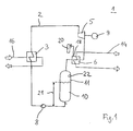
- FIG. 1 is schematically shown an ORC machine 1, as it is particularly suitable as a mobile system for utilizing the waste heat of internal combustion engines.
- the ORC machine 1 comprises, in a circulation system 2 as a heat exchanger 3, an evaporator, an expansion machine 5, a condenser 6 and a liquid pump 8.
- the illustrated ORC machine 1 operates according to the Rankine cycle, wherein the expansion machine 5 Work to drive a generator 9 is performed.
- the generator 9 is designed in particular for feeding in the recovered current into the vehicle's on-board electrical system or connected thereto.
- the working fluid 10 a hydrocarbon is used, which has a significantly higher vapor pressure compared to water.
- the working fluid 10 is in a closed circuit.
- liquid working fluid 10 is evaporated in the evaporator 3 at a high pressure.
- the expansion machine 5 which is designed as a positive displacement machine, the gaseous working fluid 10 relaxes while performing the work.
- the expanded gaseous working fluid 10 is condensed in the condenser 6 at low pressure.
- the saturation vapor pressure in the condenser 6 is about 1.2 bar.
- the condensate or the liquid working fluid 10 is collected in a storage tank 11 before it is again pumped by the pump 8 for evaporation.
- a waste heat removal 14 is provided for cooling the condenser 6, .
- this may be circulating air of a motor vehicle, wherein the heat of condensation of the working fluid of the circulating air is supplied for heating the passenger compartment, for example.
- the condenser 6 is designed as an air condenser in which the working fluid 10 to be cooled flows in the interior of flow-around tubes.
- the heat is supplied to the evaporator 3 via a waste heat supply 16.
- the evaporator 3 is supplied via a suitable heat exchange heat from the exhaust gas of the vehicle engine.
- heat can be supplied from the cooling circuit of the internal combustion engine.
- the waste heat of the internal combustion engine and the exhaust gas generated can be supplied to the evaporator 3 in total via a corresponding third medium.
- a supply point 18 for introducing a non-condensing auxiliary gas 20 into the circuit of the ORC machine 1 is provided on the condenser 6.
- a specific amount of substance x i of the auxiliary gas 20 can be introduced into the circulation of the ORC machine.
- the amount of substance x i is dimensioned so that in the flow of the pump 8, the partial pressure of the auxiliary gas 20 and the saturation vapor pressure of the working fluid 10 (resulting from the condensation in the condenser 6) added to a system pressure such that after switching on the pump, the saturation vapor pressure of Working fluid is not fallen below.
- the amount of substance x i is dimensioned such that the resulting partial pressure of the auxiliary gas is greater than the suction pressure corresponding to the NPSH value of the pump. In this respect, cavitation is prevented in the flow and in particular at the suction nozzle of the liquid pump. Since the saturation vapor pressure of the working fluid 10 does not fall below during operation, there are no vapor bubbles formed there.
- the flow height 21 (shown schematically here) is clearly lowered compared to the NPSH value of the liquid pump 8 to only a few tens of centimeters.
- a sensor 22 for measuring the concentration of the auxiliary gas 20 is arranged in the storage tank 11.
Landscapes
- Engineering & Computer Science (AREA)
- Chemical & Material Sciences (AREA)
- Combustion & Propulsion (AREA)
- Mechanical Engineering (AREA)
- General Engineering & Computer Science (AREA)
- Engine Equipment That Uses Special Cycles (AREA)
Priority Applications (1)
| Application Number | Priority Date | Filing Date | Title |
|---|---|---|---|
| PL10782537T PL2499343T3 (pl) | 2009-11-14 | 2010-10-30 | Maszyna termodynamiczna oraz sposób jej eksploatacji |
Applications Claiming Priority (2)
| Application Number | Priority Date | Filing Date | Title |
|---|---|---|---|
| DE102009053390A DE102009053390B3 (de) | 2009-11-14 | 2009-11-14 | Thermodynamische Maschine sowie Verfahren zu deren Betrieb |
| PCT/EP2010/006640 WO2011057724A2 (de) | 2009-11-14 | 2010-10-30 | Thermodynamische maschine sowie verfahren zu deren betrieb |
Publications (2)
| Publication Number | Publication Date |
|---|---|
| EP2499343A2 EP2499343A2 (de) | 2012-09-19 |
| EP2499343B1 true EP2499343B1 (de) | 2013-12-11 |
Family
ID=43927322
Family Applications (1)
| Application Number | Title | Priority Date | Filing Date |
|---|---|---|---|
| EP10782537.4A Active EP2499343B1 (de) | 2009-11-14 | 2010-10-30 | Thermodynamische maschine sowie verfahren zu deren betrieb |
Country Status (14)
| Country | Link |
|---|---|
| US (1) | US8646273B2 (pl) |
| EP (1) | EP2499343B1 (pl) |
| JP (1) | JP5608755B2 (pl) |
| KR (1) | KR101752160B1 (pl) |
| CN (1) | CN102639818B (pl) |
| BR (1) | BR112012011409B1 (pl) |
| CA (1) | CA2780791C (pl) |
| DE (1) | DE102009053390B3 (pl) |
| ES (1) | ES2447827T3 (pl) |
| IL (1) | IL219426A (pl) |
| MX (1) | MX2012005586A (pl) |
| PL (1) | PL2499343T3 (pl) |
| RU (1) | RU2534330C2 (pl) |
| WO (1) | WO2011057724A2 (pl) |
Families Citing this family (20)
| Publication number | Priority date | Publication date | Assignee | Title |
|---|---|---|---|---|
| DE102012000100A1 (de) * | 2011-01-06 | 2012-07-12 | Cummins Intellectual Property, Inc. | Rankine-kreisprozess-abwärmenutzungssystem |
| DE202012101448U1 (de) * | 2012-04-19 | 2013-07-22 | Gunter Krauss | Stickstoffantriebssystem |
| US9284857B2 (en) * | 2012-06-26 | 2016-03-15 | The Regents Of The University Of California | Organic flash cycles for efficient power production |
| DE102012024017B4 (de) * | 2012-12-08 | 2016-03-10 | Pegasus Energietechnik AG | Vorrichtung zum Umwandeln von thermischer Energie mit einer Druckerhöhungseinrichtung |
| DE202013100814U1 (de) * | 2013-01-11 | 2014-04-14 | Becker Marine Systems Gmbh & Co. Kg | Vorrichtung zur Erzeugung von Energie |
| DE102013202285A1 (de) * | 2013-02-13 | 2014-08-14 | Andrews Nawar | Verfahren und Vorrichtung zur Erzeugung von Energie, insbesondere elektrischer Energie |
| EP2865854B1 (de) | 2013-10-23 | 2021-08-18 | Orcan Energy AG | Vorrichtung und Verfahren zum zuverlässigen Starten von ORC Systemen |
| WO2015099417A1 (ko) * | 2013-12-23 | 2015-07-02 | 김영선 | 전기자동차 발전시스템 |
| DE102014002336A1 (de) * | 2014-02-12 | 2015-08-13 | Nawar Andrews | Verfahren und Vorrichtung zur Erzeugung von Energie, insbesondere elektrischer Energie |
| FR3020090B1 (fr) * | 2014-04-16 | 2019-04-12 | IFP Energies Nouvelles | Dispositif de controle d'un circuit ferme fonctionnant selon un cycle de rankine et procede utilisant un tel dispositif |
| EP2933442B1 (de) | 2014-04-16 | 2016-11-02 | Orcan Energy AG | Vorrichtung und Verfahren zur Erkennung von Leckagen in geschlossenen Kreisprozessen |
| JP6423614B2 (ja) | 2014-05-13 | 2018-11-14 | 株式会社神戸製鋼所 | 熱エネルギー回収装置 |
| US20170130612A1 (en) * | 2014-06-26 | 2017-05-11 | Volvo Truck Corporation | System for a heat energy recovery |
| PL3006682T3 (pl) * | 2014-10-07 | 2023-01-30 | Orcan Energy Ag | Urządzenie i sposób obsługi stacji wymiany ciepła |
| EP3015660B1 (de) | 2014-10-31 | 2018-12-05 | Orcan Energy AG | Verfahren zum betreiben eines thermodynamischen kreisprozesses |
| ES2586425B1 (es) * | 2015-02-19 | 2018-06-08 | Expander Tech, S.L. | Sistema de anti-cavitación eficiente de bombas para ciclos de potencia rankine orgánicos |
| FR3084913B1 (fr) | 2018-08-09 | 2020-07-31 | Faurecia Systemes Dechappement | Systeme thermique a circuit rankine |
| DE102019003744A1 (de) * | 2019-05-23 | 2020-11-26 | Madalin Vinersar | Vorrichtung und Verfahren zur Energieerzeugung, insbesondere zur Erzeugung von elektrischem Strom |
| JP7716288B2 (ja) | 2021-09-17 | 2025-07-31 | 三菱重工マリンマシナリ株式会社 | 動力回収システム |
| SE547323C2 (en) | 2023-02-10 | 2025-07-01 | Climeon Ab | Thermodynamic system comprising a pump assembly |
Family Cites Families (26)
| Publication number | Priority date | Publication date | Assignee | Title |
|---|---|---|---|---|
| DE7225314U (de) * | 1971-07-06 | 1973-11-15 | Sundstrand Corp | Erhitzer-Ekonomiser-Vorrichtung für eine Dampfkraftanlage mit organischem Arbeitsmittel |
| US4291232A (en) * | 1979-07-09 | 1981-09-22 | Cardone Joseph T | Liquid powered, closed loop power generating system and process for using same |
| JPS58144613A (ja) * | 1982-02-22 | 1983-08-29 | Mitsubishi Heavy Ind Ltd | 発電プラントのホツトウエルタンク |
| JPS5951109A (ja) * | 1982-09-17 | 1984-03-24 | Hitachi Ltd | 蒸気原動所の復水器真空保持装置 |
| JPS6020093A (ja) * | 1983-07-14 | 1985-02-01 | Mitsubishi Heavy Ind Ltd | 熱回収系 |
| US4738111A (en) | 1985-12-04 | 1988-04-19 | Edwards Thomas C | Power unit for converting heat to power |
| JPS62210391A (ja) * | 1986-03-10 | 1987-09-16 | Toshiba Corp | 地熱発電システムにおける復水器のガス除去装置 |
| IL101002A (en) * | 1991-02-20 | 2001-01-28 | Ormat Turbines 1965 Ltd | Method of and means for using a two phase fluid for generating power in a rankine cycle power plant |
| RU2148722C1 (ru) * | 1998-09-24 | 2000-05-10 | Научно-исследовательская фирма "Эн-Ал" | Энергетический цикл, в котором используется смесь |
| DE19853206C1 (de) * | 1998-11-18 | 2000-03-23 | Siemens Ag | Verfahren zur Kondensatanwärmung in einem Speisewasserbehälter eines Dampfkraftwerkes |
| JP2004353517A (ja) | 2003-05-28 | 2004-12-16 | Ebara Corp | 発電装置 |
| US6986251B2 (en) | 2003-06-17 | 2006-01-17 | Utc Power, Llc | Organic rankine cycle system for use with a reciprocating engine |
| BRPI0413986A (pt) | 2003-08-27 | 2006-11-07 | Ttl Dynamics Ltd | sistema de recuperação de energia, usos de hfe-7100 ou hexano ou água e de um dos alcanos, sistema de geração de energia elétrica, unidade de turbina de afluxo radial, mancal, acoplamento magnético rotativo, método realizado em um sistema de recuperação de energia para extrair energia a apartir de uma fonte de calor residual, método de controle de um sistema de recuperação de energia, e, sistemas de controle programável e de purificação de fluido de trabalho para um sistema de conversão de energia |
| US7131290B2 (en) | 2003-10-02 | 2006-11-07 | Honda Motor Co., Ltd. | Non-condensing gas discharge device of condenser |
| EP1624269A3 (en) | 2003-10-02 | 2006-03-08 | HONDA MOTOR CO., Ltd. | Cooling control device for condenser |
| US7225621B2 (en) * | 2005-03-01 | 2007-06-05 | Ormat Technologies, Inc. | Organic working fluids |
| JP4493531B2 (ja) * | 2005-03-25 | 2010-06-30 | 株式会社デンソー | 膨張機付き流体ポンプおよびそれを用いたランキンサイクル |
| GB0513463D0 (en) * | 2005-07-01 | 2005-08-10 | Highview Entpr Ltd | Injection apparatus for cryogenic engines |
| US20090320478A1 (en) * | 2006-01-04 | 2009-12-31 | General Electric Company | Reduced boundary layer separation steam jet air ejector assembly and method |
| RU2304722C1 (ru) * | 2006-05-11 | 2007-08-20 | Общество с ограниченной ответственностью "Теплофизика-2Т" | Энергетический цикл а.в. серогодского |
| GB2442743A (en) * | 2006-10-12 | 2008-04-16 | Energetix Group Ltd | A Closed Cycle Heat Transfer Device |
| SE530868C2 (sv) * | 2007-02-09 | 2008-09-30 | Volvo Lastvagnar Ab | Kylsystem |
| JP2008231981A (ja) * | 2007-03-19 | 2008-10-02 | Sanden Corp | 内燃機関の廃熱利用装置 |
| DE102008013545B4 (de) * | 2008-03-11 | 2015-11-05 | Alfred Becker Gmbh | Vorrichtung und Verfahren zur Abwärmenutzung mittels eines ORC-Prozesses |
| US8297355B2 (en) * | 2008-08-22 | 2012-10-30 | Texaco Inc. | Using heat from produced fluids of oil and gas operations to produce energy |
| CN101408115B (zh) * | 2008-11-11 | 2011-04-06 | 西安交通大学 | 一种适用于车用发动机余热回收的热力循环系统 |
-
2009
- 2009-11-14 DE DE102009053390A patent/DE102009053390B3/de not_active Expired - Fee Related
-
2010
- 2010-10-30 CA CA2780791A patent/CA2780791C/en active Active
- 2010-10-30 JP JP2012538221A patent/JP5608755B2/ja active Active
- 2010-10-30 MX MX2012005586A patent/MX2012005586A/es active IP Right Grant
- 2010-10-30 KR KR1020127012300A patent/KR101752160B1/ko active Active
- 2010-10-30 BR BR112012011409-3A patent/BR112012011409B1/pt active IP Right Grant
- 2010-10-30 ES ES10782537.4T patent/ES2447827T3/es active Active
- 2010-10-30 CN CN201080051437.8A patent/CN102639818B/zh active Active
- 2010-10-30 WO PCT/EP2010/006640 patent/WO2011057724A2/de not_active Ceased
- 2010-10-30 PL PL10782537T patent/PL2499343T3/pl unknown
- 2010-10-30 RU RU2012124416/06A patent/RU2534330C2/ru active
- 2010-10-30 EP EP10782537.4A patent/EP2499343B1/de active Active
- 2010-10-30 US US13/508,422 patent/US8646273B2/en active Active
-
2012
- 2012-04-25 IL IL219426A patent/IL219426A/en active IP Right Grant
Also Published As
| Publication number | Publication date |
|---|---|
| PL2499343T3 (pl) | 2014-05-30 |
| IL219426A0 (en) | 2012-06-28 |
| RU2534330C2 (ru) | 2014-11-27 |
| CN102639818A (zh) | 2012-08-15 |
| US8646273B2 (en) | 2014-02-11 |
| JP2013510984A (ja) | 2013-03-28 |
| WO2011057724A3 (de) | 2011-10-13 |
| CA2780791C (en) | 2015-06-02 |
| RU2012124416A (ru) | 2013-12-20 |
| JP5608755B2 (ja) | 2014-10-15 |
| CA2780791A1 (en) | 2011-05-19 |
| BR112012011409A2 (pt) | 2016-05-03 |
| KR20120115225A (ko) | 2012-10-17 |
| KR101752160B1 (ko) | 2017-06-29 |
| EP2499343A2 (de) | 2012-09-19 |
| ES2447827T3 (es) | 2014-03-13 |
| IL219426A (en) | 2016-10-31 |
| MX2012005586A (es) | 2012-05-29 |
| DE102009053390B3 (de) | 2011-06-01 |
| US20120227404A1 (en) | 2012-09-13 |
| BR112012011409B1 (pt) | 2020-02-11 |
| WO2011057724A2 (de) | 2011-05-19 |
| CN102639818B (zh) | 2015-03-25 |
Similar Documents
| Publication | Publication Date | Title |
|---|---|---|
| EP2499343B1 (de) | Thermodynamische maschine sowie verfahren zu deren betrieb | |
| DE68926220T2 (de) | Verfahren und Vorrichtung zur Dampfkrafterzeugung | |
| EP2748434B1 (de) | Anlage zur speicherung thermischer energie | |
| DE102006043139B4 (de) | Vorrichtung zur Gewinnung von mechanischer oder elektrischer Energie aus der Abwärme eines Verbrennungsmotors eines Kraftfahrzeugs | |
| EP2357349B2 (de) | System zur Abwärmenutzung einer Brennkraftmaschine mit Einfrierschutzeinrichtung | |
| EP2900943B1 (de) | Kraft-wärme-kraftwerk und verfahren zum betrieb eines kraft-wärme-kraftwerks | |
| EP3186506B1 (de) | Vorrichtung und verfahren zum speichern von energie | |
| DE102014223626A1 (de) | Vorrichtung und Verfahren zur Rückgewinnung von Abwärmeenergie und ein Nutzkraftfahrzeug | |
| DE102011117054A1 (de) | Vorrichtung zur Energierückgewinnung aus einem Abwärmestrom einer Verbrennungskraftmaschine in einem Fahrzeug mit einem Arbeitsmedium-Kreislauf und Verfahren zur Leckage-Erkennung in einem Arbeitsmedium-Kreislauf | |
| DE3022284A1 (de) | Verfahren und einrichtung zum speichern und hochtransformieren der temperatur von waerme | |
| EP4036382B1 (de) | Nutzung einer wärmequelle zur stromerzeugung und luftfahrzeug mit kühlsystem | |
| EP2653668A1 (de) | Verfahren zum Laden und Entladen eines Wärmespeichers und Anlage zur Speicherung und Abgabe von thermischer Energie, geeignet für dieses Verfahren | |
| DE102009042584A1 (de) | Wärmeübertrager und System zur Nutzung von Abwärme eines Verbrennungsmotors | |
| DE102014212019A1 (de) | Kühl- und Energierückgewinnungsystem | |
| DE112016000565B4 (de) | Einheit zum Umwandeln von Wärme in mechanische Energie | |
| DE102013210425A1 (de) | Anlage und Verfahren zum Aufbereiten von Wasser | |
| DE102010054667B3 (de) | Frostsichere Dampfkreisprozessvorrichtung und Verfahren für deren Betrieb | |
| DE102016215836A1 (de) | Vorrichtung und Verfahren zur Energierückgewinnung | |
| WO2012152602A1 (de) | Leitungskreis und verfahren zum betreiben eines leitungskreises zur abwärmenutzung einer brennkraftmaschine | |
| DE102013016461A1 (de) | Verfahren zum Betrieb eines Niedertemperaturkraftwerkes, sowie Niedertemperaturkraftwerk selbst | |
| WO2017081248A1 (de) | Anordnung und verfahren zur rückgewinnung von energie aus der abwärme mindestens einer brennkraftmaschine | |
| DE102011101665A1 (de) | Wärmeeinheit zum Erzeugen elektrischer Energie | |
| DE102022125604B4 (de) | System und Verfahren zur Energiewandlung und Energiespeicherung | |
| EP2951407A2 (de) | Verfahren zum betrieb eines niedertemperaturkraftwerkes, sowie niedertemperaturkraftwerk selbst | |
| DE102010034229A1 (de) | Brennkraftmaschine mit zumindest zwei Wärmerückgewinnungsvorrichtungen und ein Verfahren zum Betrieb der Brennkraftmaschine |
Legal Events
| Date | Code | Title | Description |
|---|---|---|---|
| PUAI | Public reference made under article 153(3) epc to a published international application that has entered the european phase |
Free format text: ORIGINAL CODE: 0009012 |
|
| 17P | Request for examination filed |
Effective date: 20120502 |
|
| AK | Designated contracting states |
Kind code of ref document: A2 Designated state(s): AL AT BE BG CH CY CZ DE DK EE ES FI FR GB GR HR HU IE IS IT LI LT LU LV MC MK MT NL NO PL PT RO RS SE SI SK SM TR |
|
| DAX | Request for extension of the european patent (deleted) | ||
| GRAP | Despatch of communication of intention to grant a patent |
Free format text: ORIGINAL CODE: EPIDOSNIGR1 |
|
| INTG | Intention to grant announced |
Effective date: 20130620 |
|
| GRAS | Grant fee paid |
Free format text: ORIGINAL CODE: EPIDOSNIGR3 |
|
| GRAA | (expected) grant |
Free format text: ORIGINAL CODE: 0009210 |
|
| AK | Designated contracting states |
Kind code of ref document: B1 Designated state(s): AL AT BE BG CH CY CZ DE DK EE ES FI FR GB GR HR HU IE IS IT LI LT LU LV MC MK MT NL NO PL PT RO RS SE SI SK SM TR |
|
| REG | Reference to a national code |
Ref country code: GB Ref legal event code: FG4D Free format text: NOT ENGLISH |
|
| REG | Reference to a national code |
Ref country code: CH Ref legal event code: EP |
|
| REG | Reference to a national code |
Ref country code: AT Ref legal event code: REF Ref document number: 644736 Country of ref document: AT Kind code of ref document: T Effective date: 20140115 |
|
| REG | Reference to a national code |
Ref country code: IE Ref legal event code: FG4D Free format text: LANGUAGE OF EP DOCUMENT: GERMAN |
|
| REG | Reference to a national code |
Ref country code: DE Ref legal event code: R096 Ref document number: 502010005668 Country of ref document: DE Effective date: 20140206 |
|
| REG | Reference to a national code |
Ref country code: CH Ref legal event code: NV Representative=s name: E. BLUM AND CO. AG PATENT- UND MARKENANWAELTE , CH |
|
| REG | Reference to a national code |
Ref country code: SE Ref legal event code: TRGR |
|
| REG | Reference to a national code |
Ref country code: NL Ref legal event code: T3 |
|
| REG | Reference to a national code |
Ref country code: ES Ref legal event code: FG2A Ref document number: 2447827 Country of ref document: ES Kind code of ref document: T3 Effective date: 20140313 |
|
| PG25 | Lapsed in a contracting state [announced via postgrant information from national office to epo] |
Ref country code: NO Free format text: LAPSE BECAUSE OF FAILURE TO SUBMIT A TRANSLATION OF THE DESCRIPTION OR TO PAY THE FEE WITHIN THE PRESCRIBED TIME-LIMIT Effective date: 20140311 Ref country code: FI Free format text: LAPSE BECAUSE OF FAILURE TO SUBMIT A TRANSLATION OF THE DESCRIPTION OR TO PAY THE FEE WITHIN THE PRESCRIBED TIME-LIMIT Effective date: 20131211 Ref country code: HR Free format text: LAPSE BECAUSE OF FAILURE TO SUBMIT A TRANSLATION OF THE DESCRIPTION OR TO PAY THE FEE WITHIN THE PRESCRIBED TIME-LIMIT Effective date: 20131211 Ref country code: LT Free format text: LAPSE BECAUSE OF FAILURE TO SUBMIT A TRANSLATION OF THE DESCRIPTION OR TO PAY THE FEE WITHIN THE PRESCRIBED TIME-LIMIT Effective date: 20131211 |
|
| REG | Reference to a national code |
Ref country code: LT Ref legal event code: MG4D |
|
| PG25 | Lapsed in a contracting state [announced via postgrant information from national office to epo] |
Ref country code: RS Free format text: LAPSE BECAUSE OF FAILURE TO SUBMIT A TRANSLATION OF THE DESCRIPTION OR TO PAY THE FEE WITHIN THE PRESCRIBED TIME-LIMIT Effective date: 20131211 Ref country code: CY Free format text: LAPSE BECAUSE OF FAILURE TO SUBMIT A TRANSLATION OF THE DESCRIPTION OR TO PAY THE FEE WITHIN THE PRESCRIBED TIME-LIMIT Effective date: 20131211 Ref country code: LV Free format text: LAPSE BECAUSE OF FAILURE TO SUBMIT A TRANSLATION OF THE DESCRIPTION OR TO PAY THE FEE WITHIN THE PRESCRIBED TIME-LIMIT Effective date: 20131211 |
|
| REG | Reference to a national code |
Ref country code: PL Ref legal event code: T3 |
|
| PG25 | Lapsed in a contracting state [announced via postgrant information from national office to epo] |
Ref country code: EE Free format text: LAPSE BECAUSE OF FAILURE TO SUBMIT A TRANSLATION OF THE DESCRIPTION OR TO PAY THE FEE WITHIN THE PRESCRIBED TIME-LIMIT Effective date: 20131211 Ref country code: IS Free format text: LAPSE BECAUSE OF FAILURE TO SUBMIT A TRANSLATION OF THE DESCRIPTION OR TO PAY THE FEE WITHIN THE PRESCRIBED TIME-LIMIT Effective date: 20140411 |
|
| PG25 | Lapsed in a contracting state [announced via postgrant information from national office to epo] |
Ref country code: SK Free format text: LAPSE BECAUSE OF FAILURE TO SUBMIT A TRANSLATION OF THE DESCRIPTION OR TO PAY THE FEE WITHIN THE PRESCRIBED TIME-LIMIT Effective date: 20131211 Ref country code: CZ Free format text: LAPSE BECAUSE OF FAILURE TO SUBMIT A TRANSLATION OF THE DESCRIPTION OR TO PAY THE FEE WITHIN THE PRESCRIBED TIME-LIMIT Effective date: 20131211 Ref country code: RO Free format text: LAPSE BECAUSE OF FAILURE TO SUBMIT A TRANSLATION OF THE DESCRIPTION OR TO PAY THE FEE WITHIN THE PRESCRIBED TIME-LIMIT Effective date: 20131211 Ref country code: PT Free format text: LAPSE BECAUSE OF FAILURE TO SUBMIT A TRANSLATION OF THE DESCRIPTION OR TO PAY THE FEE WITHIN THE PRESCRIBED TIME-LIMIT Effective date: 20140411 |
|
| REG | Reference to a national code |
Ref country code: DE Ref legal event code: R097 Ref document number: 502010005668 Country of ref document: DE |
|
| PLBE | No opposition filed within time limit |
Free format text: ORIGINAL CODE: 0009261 |
|
| STAA | Information on the status of an ep patent application or granted ep patent |
Free format text: STATUS: NO OPPOSITION FILED WITHIN TIME LIMIT |
|
| PG25 | Lapsed in a contracting state [announced via postgrant information from national office to epo] |
Ref country code: DK Free format text: LAPSE BECAUSE OF FAILURE TO SUBMIT A TRANSLATION OF THE DESCRIPTION OR TO PAY THE FEE WITHIN THE PRESCRIBED TIME-LIMIT Effective date: 20131211 |
|
| 26N | No opposition filed |
Effective date: 20140912 |
|
| REG | Reference to a national code |
Ref country code: DE Ref legal event code: R097 Ref document number: 502010005668 Country of ref document: DE Effective date: 20140912 |
|
| PG25 | Lapsed in a contracting state [announced via postgrant information from national office to epo] |
Ref country code: SI Free format text: LAPSE BECAUSE OF FAILURE TO SUBMIT A TRANSLATION OF THE DESCRIPTION OR TO PAY THE FEE WITHIN THE PRESCRIBED TIME-LIMIT Effective date: 20131211 |
|
| PG25 | Lapsed in a contracting state [announced via postgrant information from national office to epo] |
Ref country code: MC Free format text: LAPSE BECAUSE OF FAILURE TO SUBMIT A TRANSLATION OF THE DESCRIPTION OR TO PAY THE FEE WITHIN THE PRESCRIBED TIME-LIMIT Effective date: 20131211 Ref country code: LU Free format text: LAPSE BECAUSE OF FAILURE TO SUBMIT A TRANSLATION OF THE DESCRIPTION OR TO PAY THE FEE WITHIN THE PRESCRIBED TIME-LIMIT Effective date: 20141030 |
|
| REG | Reference to a national code |
Ref country code: IE Ref legal event code: MM4A |
|
| REG | Reference to a national code |
Ref country code: FR Ref legal event code: PLFP Year of fee payment: 6 |
|
| PG25 | Lapsed in a contracting state [announced via postgrant information from national office to epo] |
Ref country code: IE Free format text: LAPSE BECAUSE OF NON-PAYMENT OF DUE FEES Effective date: 20141030 |
|
| PG25 | Lapsed in a contracting state [announced via postgrant information from national office to epo] |
Ref country code: SM Free format text: LAPSE BECAUSE OF FAILURE TO SUBMIT A TRANSLATION OF THE DESCRIPTION OR TO PAY THE FEE WITHIN THE PRESCRIBED TIME-LIMIT Effective date: 20131211 |
|
| REG | Reference to a national code |
Ref country code: CH Ref legal event code: PFA Owner name: ORCAN ENERGY AG, DE Free format text: FORMER OWNER: ORCAN ENERGY GMBH, DE |
|
| REG | Reference to a national code |
Ref country code: DE Ref legal event code: R082 Ref document number: 502010005668 Country of ref document: DE Representative=s name: FDST PATENTANWAELTE FREIER DOERR STAMMLER TSCH, DE Ref country code: DE Ref legal event code: R081 Ref document number: 502010005668 Country of ref document: DE Owner name: ORCAN ENERGY AG, DE Free format text: FORMER OWNER: ORCAN ENERGY GMBH, 81379 MUENCHEN, DE |
|
| PG25 | Lapsed in a contracting state [announced via postgrant information from national office to epo] |
Ref country code: GR Free format text: LAPSE BECAUSE OF FAILURE TO SUBMIT A TRANSLATION OF THE DESCRIPTION OR TO PAY THE FEE WITHIN THE PRESCRIBED TIME-LIMIT Effective date: 20140312 Ref country code: BG Free format text: LAPSE BECAUSE OF FAILURE TO SUBMIT A TRANSLATION OF THE DESCRIPTION OR TO PAY THE FEE WITHIN THE PRESCRIBED TIME-LIMIT Effective date: 20131211 |
|
| REG | Reference to a national code |
Ref country code: ES Ref legal event code: PC2A Owner name: ORCAN ENERGY AG Effective date: 20160630 |
|
| PG25 | Lapsed in a contracting state [announced via postgrant information from national office to epo] |
Ref country code: MT Free format text: LAPSE BECAUSE OF FAILURE TO SUBMIT A TRANSLATION OF THE DESCRIPTION OR TO PAY THE FEE WITHIN THE PRESCRIBED TIME-LIMIT Effective date: 20131211 Ref country code: HU Free format text: LAPSE BECAUSE OF FAILURE TO SUBMIT A TRANSLATION OF THE DESCRIPTION OR TO PAY THE FEE WITHIN THE PRESCRIBED TIME-LIMIT; INVALID AB INITIO Effective date: 20101030 Ref country code: TR Free format text: LAPSE BECAUSE OF FAILURE TO SUBMIT A TRANSLATION OF THE DESCRIPTION OR TO PAY THE FEE WITHIN THE PRESCRIBED TIME-LIMIT Effective date: 20131211 |
|
| REG | Reference to a national code |
Ref country code: FR Ref legal event code: CD Owner name: ORCAN ENERGY AG, DE Effective date: 20160805 Ref country code: FR Ref legal event code: CJ Effective date: 20160805 |
|
| REG | Reference to a national code |
Ref country code: NL Ref legal event code: PD Owner name: ORCAN ENERGY AG; DE Free format text: DETAILS ASSIGNMENT: VERANDERING VAN EIGENAAR(S), VERANDERING VAN DE JURIDISCHE ENTITEIT; FORMER OWNER NAME: ORCAN ENERGY GMBH Effective date: 20160617 |
|
| REG | Reference to a national code |
Ref country code: AT Ref legal event code: PC Ref document number: 644736 Country of ref document: AT Kind code of ref document: T Owner name: ORCAN ENERGY AG, DE Effective date: 20160803 |
|
| REG | Reference to a national code |
Ref country code: FR Ref legal event code: PLFP Year of fee payment: 7 |
|
| REG | Reference to a national code |
Ref country code: FR Ref legal event code: PLFP Year of fee payment: 8 |
|
| PG25 | Lapsed in a contracting state [announced via postgrant information from national office to epo] |
Ref country code: MK Free format text: LAPSE BECAUSE OF FAILURE TO SUBMIT A TRANSLATION OF THE DESCRIPTION OR TO PAY THE FEE WITHIN THE PRESCRIBED TIME-LIMIT Effective date: 20131211 |
|
| REG | Reference to a national code |
Ref country code: FR Ref legal event code: PLFP Year of fee payment: 9 |
|
| PG25 | Lapsed in a contracting state [announced via postgrant information from national office to epo] |
Ref country code: AL Free format text: LAPSE BECAUSE OF FAILURE TO SUBMIT A TRANSLATION OF THE DESCRIPTION OR TO PAY THE FEE WITHIN THE PRESCRIBED TIME-LIMIT Effective date: 20131211 |
|
| PGFP | Annual fee paid to national office [announced via postgrant information from national office to epo] |
Ref country code: DE Payment date: 20241022 Year of fee payment: 15 |
|
| PGFP | Annual fee paid to national office [announced via postgrant information from national office to epo] |
Ref country code: FR Payment date: 20241025 Year of fee payment: 15 |
|
| PGFP | Annual fee paid to national office [announced via postgrant information from national office to epo] |
Ref country code: ES Payment date: 20241118 Year of fee payment: 15 |
|
| PGFP | Annual fee paid to national office [announced via postgrant information from national office to epo] |
Ref country code: CH Payment date: 20241101 Year of fee payment: 15 |
|
| PGFP | Annual fee paid to national office [announced via postgrant information from national office to epo] |
Ref country code: NL Payment date: 20251023 Year of fee payment: 16 |
|
| PGFP | Annual fee paid to national office [announced via postgrant information from national office to epo] |
Ref country code: GB Payment date: 20251008 Year of fee payment: 16 |
|
| PGFP | Annual fee paid to national office [announced via postgrant information from national office to epo] |
Ref country code: AT Payment date: 20251021 Year of fee payment: 16 |
|
| PGFP | Annual fee paid to national office [announced via postgrant information from national office to epo] |
Ref country code: IT Payment date: 20251031 Year of fee payment: 16 |
|
| PGFP | Annual fee paid to national office [announced via postgrant information from national office to epo] |
Ref country code: BE Payment date: 20251022 Year of fee payment: 16 |
|
| PGFP | Annual fee paid to national office [announced via postgrant information from national office to epo] |
Ref country code: SE Payment date: 20251023 Year of fee payment: 16 |
|
| REG | Reference to a national code |
Ref country code: CH Ref legal event code: U11 Free format text: ST27 STATUS EVENT CODE: U-0-0-U10-U11 (AS PROVIDED BY THE NATIONAL OFFICE) Effective date: 20260122 |
|
| PGFP | Annual fee paid to national office [announced via postgrant information from national office to epo] |
Ref country code: PL Payment date: 20251017 Year of fee payment: 16 |