EP2498686B1 - Vorrichtungen für gewebereparatur - Google Patents
Vorrichtungen für gewebereparatur Download PDFInfo
- Publication number
- EP2498686B1 EP2498686B1 EP10781765.2A EP10781765A EP2498686B1 EP 2498686 B1 EP2498686 B1 EP 2498686B1 EP 10781765 A EP10781765 A EP 10781765A EP 2498686 B1 EP2498686 B1 EP 2498686B1
- Authority
- EP
- European Patent Office
- Prior art keywords
- anchor
- cavity
- suture
- insertion member
- hole
- Prior art date
- Legal status (The legal status is an assumption and is not a legal conclusion. Google has not performed a legal analysis and makes no representation as to the accuracy of the status listed.)
- Active
Links
- 230000017423 tissue regeneration Effects 0.000 title description 7
- 238000003780 insertion Methods 0.000 claims description 87
- 230000037431 insertion Effects 0.000 claims description 87
- 210000000988 bone and bone Anatomy 0.000 description 50
- 238000000034 method Methods 0.000 description 15
- 210000001519 tissue Anatomy 0.000 description 12
- 230000000712 assembly Effects 0.000 description 9
- 238000000429 assembly Methods 0.000 description 9
- 230000008878 coupling Effects 0.000 description 6
- 238000010168 coupling process Methods 0.000 description 6
- 238000005859 coupling reaction Methods 0.000 description 6
- 238000001356 surgical procedure Methods 0.000 description 6
- 230000008439 repair process Effects 0.000 description 5
- 239000000463 material Substances 0.000 description 4
- 239000007769 metal material Substances 0.000 description 4
- 210000004872 soft tissue Anatomy 0.000 description 4
- 235000015097 nutrients Nutrition 0.000 description 3
- 239000002861 polymer material Substances 0.000 description 3
- 241001653121 Glenoides Species 0.000 description 2
- 238000001746 injection moulding Methods 0.000 description 2
- 230000003993 interaction Effects 0.000 description 2
- 229910052755 nonmetal Inorganic materials 0.000 description 2
- 241000287107 Passer Species 0.000 description 1
- 210000001264 anterior cruciate ligament Anatomy 0.000 description 1
- 230000001419 dependent effect Effects 0.000 description 1
- 238000005516 engineering process Methods 0.000 description 1
- 238000002513 implantation Methods 0.000 description 1
- 239000002184 metal Substances 0.000 description 1
- 238000012986 modification Methods 0.000 description 1
- 230000004048 modification Effects 0.000 description 1
- 230000008569 process Effects 0.000 description 1
- 238000011084 recovery Methods 0.000 description 1
- 238000010079 rubber tapping Methods 0.000 description 1
- 229910001220 stainless steel Inorganic materials 0.000 description 1
- 239000010935 stainless steel Substances 0.000 description 1
- 239000003356 suture material Substances 0.000 description 1
Images


Classifications
-
- A—HUMAN NECESSITIES
- A61—MEDICAL OR VETERINARY SCIENCE; HYGIENE
- A61B—DIAGNOSIS; SURGERY; IDENTIFICATION
- A61B17/00—Surgical instruments, devices or methods, e.g. tourniquets
- A61B17/04—Surgical instruments, devices or methods, e.g. tourniquets for suturing wounds; Holders or packages for needles or suture materials
- A61B17/0401—Suture anchors, buttons or pledgets, i.e. means for attaching sutures to bone, cartilage or soft tissue; Instruments for applying or removing suture anchors
- A61B2017/0409—Instruments for applying suture anchors
-
- A—HUMAN NECESSITIES
- A61—MEDICAL OR VETERINARY SCIENCE; HYGIENE
- A61B—DIAGNOSIS; SURGERY; IDENTIFICATION
- A61B17/00—Surgical instruments, devices or methods, e.g. tourniquets
- A61B17/04—Surgical instruments, devices or methods, e.g. tourniquets for suturing wounds; Holders or packages for needles or suture materials
- A61B17/0401—Suture anchors, buttons or pledgets, i.e. means for attaching sutures to bone, cartilage or soft tissue; Instruments for applying or removing suture anchors
- A61B2017/0412—Suture anchors, buttons or pledgets, i.e. means for attaching sutures to bone, cartilage or soft tissue; Instruments for applying or removing suture anchors having anchoring barbs or pins extending outwardly from suture anchor body
-
- A—HUMAN NECESSITIES
- A61—MEDICAL OR VETERINARY SCIENCE; HYGIENE
- A61B—DIAGNOSIS; SURGERY; IDENTIFICATION
- A61B17/00—Surgical instruments, devices or methods, e.g. tourniquets
- A61B17/04—Surgical instruments, devices or methods, e.g. tourniquets for suturing wounds; Holders or packages for needles or suture materials
- A61B17/0401—Suture anchors, buttons or pledgets, i.e. means for attaching sutures to bone, cartilage or soft tissue; Instruments for applying or removing suture anchors
- A61B2017/0414—Suture anchors, buttons or pledgets, i.e. means for attaching sutures to bone, cartilage or soft tissue; Instruments for applying or removing suture anchors having a suture-receiving opening, e.g. lateral opening
-
- A—HUMAN NECESSITIES
- A61—MEDICAL OR VETERINARY SCIENCE; HYGIENE
- A61B—DIAGNOSIS; SURGERY; IDENTIFICATION
- A61B17/00—Surgical instruments, devices or methods, e.g. tourniquets
- A61B17/04—Surgical instruments, devices or methods, e.g. tourniquets for suturing wounds; Holders or packages for needles or suture materials
- A61B17/0401—Suture anchors, buttons or pledgets, i.e. means for attaching sutures to bone, cartilage or soft tissue; Instruments for applying or removing suture anchors
- A61B2017/0427—Suture anchors, buttons or pledgets, i.e. means for attaching sutures to bone, cartilage or soft tissue; Instruments for applying or removing suture anchors having anchoring barbs or pins extending outwardly from the anchor body
- A61B2017/0435—Suture anchors, buttons or pledgets, i.e. means for attaching sutures to bone, cartilage or soft tissue; Instruments for applying or removing suture anchors having anchoring barbs or pins extending outwardly from the anchor body the barbs being separate elements mechanically linked to the anchor, e.g. by pivots
-
- A—HUMAN NECESSITIES
- A61—MEDICAL OR VETERINARY SCIENCE; HYGIENE
- A61B—DIAGNOSIS; SURGERY; IDENTIFICATION
- A61B17/00—Surgical instruments, devices or methods, e.g. tourniquets
- A61B17/04—Surgical instruments, devices or methods, e.g. tourniquets for suturing wounds; Holders or packages for needles or suture materials
- A61B17/0401—Suture anchors, buttons or pledgets, i.e. means for attaching sutures to bone, cartilage or soft tissue; Instruments for applying or removing suture anchors
- A61B2017/044—Suture anchors, buttons or pledgets, i.e. means for attaching sutures to bone, cartilage or soft tissue; Instruments for applying or removing suture anchors with a threaded shaft, e.g. screws
- A61B2017/0441—Suture anchors, buttons or pledgets, i.e. means for attaching sutures to bone, cartilage or soft tissue; Instruments for applying or removing suture anchors with a threaded shaft, e.g. screws the shaft being a rigid coil or spiral
-
- A—HUMAN NECESSITIES
- A61—MEDICAL OR VETERINARY SCIENCE; HYGIENE
- A61B—DIAGNOSIS; SURGERY; IDENTIFICATION
- A61B17/00—Surgical instruments, devices or methods, e.g. tourniquets
- A61B17/04—Surgical instruments, devices or methods, e.g. tourniquets for suturing wounds; Holders or packages for needles or suture materials
- A61B17/0401—Suture anchors, buttons or pledgets, i.e. means for attaching sutures to bone, cartilage or soft tissue; Instruments for applying or removing suture anchors
- A61B2017/0445—Suture anchors, buttons or pledgets, i.e. means for attaching sutures to bone, cartilage or soft tissue; Instruments for applying or removing suture anchors cannulated, e.g. with a longitudinal through-hole for passage of an instrument
-
- A—HUMAN NECESSITIES
- A61—MEDICAL OR VETERINARY SCIENCE; HYGIENE
- A61B—DIAGNOSIS; SURGERY; IDENTIFICATION
- A61B17/00—Surgical instruments, devices or methods, e.g. tourniquets
- A61B17/04—Surgical instruments, devices or methods, e.g. tourniquets for suturing wounds; Holders or packages for needles or suture materials
- A61B17/0401—Suture anchors, buttons or pledgets, i.e. means for attaching sutures to bone, cartilage or soft tissue; Instruments for applying or removing suture anchors
- A61B2017/0446—Means for attaching and blocking the suture in the suture anchor
- A61B2017/0448—Additional elements on or within the anchor
- A61B2017/0453—Additional elements on or within the anchor threaded elements, e.g. set screws
-
- A—HUMAN NECESSITIES
- A61—MEDICAL OR VETERINARY SCIENCE; HYGIENE
- A61B—DIAGNOSIS; SURGERY; IDENTIFICATION
- A61B17/00—Surgical instruments, devices or methods, e.g. tourniquets
- A61B17/04—Surgical instruments, devices or methods, e.g. tourniquets for suturing wounds; Holders or packages for needles or suture materials
- A61B17/0401—Suture anchors, buttons or pledgets, i.e. means for attaching sutures to bone, cartilage or soft tissue; Instruments for applying or removing suture anchors
- A61B2017/0464—Suture anchors, buttons or pledgets, i.e. means for attaching sutures to bone, cartilage or soft tissue; Instruments for applying or removing suture anchors for soft tissue
Definitions
- the present disclosure relates to tissue repair devices, and more specifically, to anchors, anchor assemblies, and delivery devices for use in securing tissue to bone.
- EP 1 825 817 A1 discloses an anchor element and a clamping element for knot-free fixation of tissue on a bone.
- DE 10 2008 016607 A1 discloses a device for implantation in a bone and a system for controlled loading of a reconstructed anterior cruciate ligament.
- EP 1 491 162 A2 discloses a graft fixation device including a radially expandable sheath.
- US 2007 005068 A1 discloses a knotless suture anchor comprising a tubular housing for selective expansion, and an expander.
- WO 02/38059 A2 discloses a tension band clip including an outer portion with female threads and an inner male portion with male threads.
- WO 2009/055800 A1 discloses an anchor assembly including an anchor and an insertion member.
- the invention is as defined in claim 1 with further preferred embodiments disclosed in the dependent claims.
- the present disclosure relates to an anchor assembly.
- the anchor assembly includes an anchor defining a cavity, an opening to the cavity and a transverse through hole extending through the anchor; and a headless insertion member configured for arrangement within the anchor cavity, the insertion member including a body and a cannulation extending a partial length of the insertion member.
- the insertion member includes threads located along an outer surface of the insertion member from a proximal end to a distal end, such that the insertion member comprises a fully threaded body; wherein the anchor cavity includes threads extending from the cavity opening a length of the cavity, wherein the through hole intersects the cavity and the cavity extends beyond the through hole, the through hole defining first and second openings on opposing sides of the cavity, wherein the insertion member threads and cavity threads are configured to engage each other and the insertion member is movable within the cavity so as to cover the first and second openings when in a suture fixation position.
- the cannulation is triangular shaped.
- the anchor cavity includes a threaded proximal portion and a non-threaded distal portion.
- the distal portion of the insertion member includes two segments and a tapered portion located between the segments.
- the present disclosure relates to an anchor assembly.
- the anchor assembly includes an anchor defining a cavity and an opening to the cavity and a headless insertion member configured for arrangement within the anchor cavity, the insertion member cannulation extending a partial length of the insertion member.
- the cannulation is triangular shaped.
- the anchor cavity includes a threaded proximal portion and a non-threaded distal portion.
- the distal portion of the insertion member includes two segments and a tapered portion located between the segments.
- the present disclosure relates to an anchor assembly.
- the anchor assembly includes an anchor defining a cavity and an opening to the cavity and a headless insertion member configured for arrangement within the anchor cavity, the insertion member including a fully threaded body and a cannulation extending a partial length of the insertion member.
- the present disclosure relates to a surgical device.
- the surgical device includes a shaft including an outer member and an inner member slidably received within the outer member, the outer member including an inner surface having threads and the inner member including an outer surface having threads; a handle coupled to the shaft; and a knob coupled to the inner member, wherein the threads of the inner member and the threads of the outer member are engaged to allow for coupling of the inner member and the outer member and movement of the outer member relative to the inner member upon rotation of the knob.
- the inner member is triangular-shaped.
- the inner member includes a depth stop.
- the outer member includes a tip extending from an end of the outer member. In a further embodiment, the tip is square-shaped.
- the present disclosure relates to an anchor assembly.
- the anchor assembly including an anchor defining a cavity and an opening to the cavity, the cavity including a non-threaded proximal portion and a threaded distal portion; and a headless insertion member configured for arrangement within the anchor cavity, the insertion member including a body and a cannulation extending a partial length of the insertion member, the body including a threaded proximal portion and a non-threaded distal portion.
- the proximal portion is square-shaped.
- the present disclosure relates to an anchor.
- the anchor includes a body defining a cavity and an opening to the cavity, the body including an outer surface and channels extending from the outer surface to the cavity.
- the body includes barbs, the channels located between the barbs.
- the outer surface includes slots, the slots intersecting the barbs.
- the present disclosure relates to an anchor assembly.
- the anchor assembly including an anchor defining a cavity and an opening to the cavity, the anchor including a body having an outer surface and barbs extending from the body and alternating in direction along the length of the body; and a headless insertion member configured for arrangement within the anchor cavity, the insertion member including a body and a cannulation extending a partial length of the insertion member.
- the anchor assembly includes an anchor including an outer body and an inner body coupled to the outer body, the outer body including a first feature and a second feature, the inner body including a first feature and a second feature, the first feature of the inner body and the first feature of the outer body engaged to allow for non-rotation of the inner body relative to the outer body and the second feature of the inner body and the second feature of the outer body engaged to allow for non-movement of the inner body relative to the outer body in an axial direction; and a headless insertion member configured for arrangement within the inner body, the insertion member including a body and a cannulation extending a partial length of the insertion member.
- FIGs. 1-7 , 28- 33 , 34- 37B , 38- 50 are not encompassed by the wording of the claims but are considered as useful for understanding the invention. Methods of tissue repair and other surgical methods are not part of the claimed invention but considered as useful for the understanding of the invention.
- Figs. 1 , 2A-2B , and 3A-3B show a first embodiment of the anchor assembly 10 of the present disclosure and its components.
- the assembly 10 includes the anchor 20 and the insertion member 30.
- the anchor 20 includes a proximal portion 21, a distal portion 22, and an inner cavity 23.
- An opening 24 to the cavity 23 is located at the proximal portion 21 of the anchor 20.
- the anchor 20 also includes a transverse hole 25 extending through the anchor 20.
- the through hole 25 is for housing of a flexible member, such as suture. Openings 25a,b are located at each end of the through hole 25.
- the outer surface 27 of the proximal portion 21 also includes barbs 28 for substantially reducing the possibility of removal of the anchor 20 when inserted into bone.
- the outer surface 27 also includes at least two slots 29 extending from the openings 25a,b of the through hole 25. The slots 29 intersect the barbs 28 and are configured for housing of the suture after positioning of the anchor 20 in bone.
- the cavity 23 extends into and beyond the through hole 25 and includes a threaded proximal portion 23a and a non-threaded distal portion 23b.
- the insertion member 30 includes a headless body 31 having a threaded proximal portion 31a and a non-threaded distal portion 31b.
- the distal portion 31b includes two segments 31b', 31b" and a tapered portion 31c located between the segments 31b', 31b".
- Segment 31b" has a flat end portion 31d.
- the member 30 includes a triangular-shaped cannulation 31e that extends a partial length of the member 30.
- the threads 31a' are configured for engagement with the threads 23c of the cavity 23 when the insertion member 30 is arranged within the cavity 23, as will be further explained below.
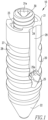
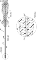
- Figs. 4-7 show the delivery device 40 of the present disclosure.
- the device 40 includes a shaft 41, a handle 42 coupled to the shaft 41, and a knob 43 coupled to the handle 42.
- the shaft 41 includes an outer member 41a and an inner member 41b slidably disposed within and coupled to the outer member 41a.
- the inner member 41b includes a distal end 41b' configured for disposal within the cannulation 31e of the insertion member 30 and a proximal end 41b" coupled to the knob 43.
- the end 41b' is of a diameter such that it engages the wall 31e' of the cannulation 31e, thereby allowing movement of the member 30 when the knob 43 is rotated, as will be further described below.
- the outer member 41a includes prongs 41c located at a distal end 41a' of the outer member 41a and a proximal end 41a" coupled to the handle 42.
- suture 44 Prior to use, suture 44 is disposed within the through hole 25 and ends 44a,44b of the suture 44 are fixed to suture holders 45 located on handle 42.
- the suture 44 helps to keep anchor 20 coupled to the shaft 41.
- the delivery device 40 and its components, especially the handle 42 and knob 43, is similar to the delivery device shown and described in US Patent Application Publication 20100016869 .
- the ends 44a,44b of the suture 44 are also housed within channels 46 that extend along the shaft 41.
- a suture threader 11000 is also releasably coupled to the shaft 41. Threader 11000 includes a clip 11000a and a loop of suture 11000b coupled to the clip 11000a. Suture loop 11000b is disposed within the through hole 25 and placed around the clip 11000a.
- the prongs 41c are disposed within the depressions 26. Once the anchor assembly 10 is disposed within bone, the prongs 41c help to hold the anchor 20 stationary while the insertion member 30 is moved relative to the anchor 20 via rotation of the knob 43. As will be further described below, Fig. 5 shows the location of the insertion member 30 prior to fixation of suture within the cavity 23, while Fig. 6 shows the location of the insertion member 30 after fixation of suture within the cavity 23.
- the non-threaded distal portion 31b is configured to be housed within the non-threaded distal portion 23b of the anchor 20.
- the proximal end 41b" of the inner member 41b includes threads 41d on an outer surface 41e of the inner member 41b and the proximal end 41a" of the outer member 41a includes threads 41f on an inner surface 41g of the outer member 41a. Threads 41f engage threads 41d to allow for coupling of the outer and inner members 41a, 41b and axial movement of the inner member 41b relative to the outer member 41a, via rotation of the knob 43. Axial movement of the inner member 41b relative to the outer member 41a allows for axial movement of the insertion member 30 to the two locations shown in Figs. 5 and 6 .
- Figs. 8-12 show a second embodiment of the anchor assembly 100 of the present disclosure and its components.
- the assembly 100 includes the anchor 200 and the insertion member 300.
- the anchor 200 includes a proximal portion 210, a distal portion 220, and an inner cavity 230.
- An opening 240 to the cavity 230 is located at the proximal portion 210 of the anchor 200.
- the anchor 200 also includes a transverse hole 250 extending through the anchor 200.
- the through hole 250 is for housing of a flexible member, such as suture. Openings 250a,b are located at each end of the through hole 250.
- the outer surface 270 of the proximal portion 210 also includes barbs 280 for substantially reducing the possibility of removal of the anchor 200 when inserted into bone.
- the outer surface 270 also includes at least two slots 290 extending from the openings 250a,b of the through hole 250.
- the slots 290 intersect the barbs 280 and are configured for housing of the suture after positioning of the anchor 200 in bone.
- the cavity 230 extends into and beyond the through hole 250.
- a pair of depressions 260 are also shown in Fig. 10 , each of which is located adjacent to the cavity 230.
- the depressions 260 are for housing of a delivery device, as will be further explained later.
- the insertion member 300 includes a body 310 having threads 310a, a distal portion 310b, and a proximal portion 310c. As shown in Figs. 8 , 11, and 12 , the member 300 includes a triangular-shaped cannulation 310d that extends a partial length of the member 300.
- the threads 310a are configured for engagement with the threads 230c of the cavity 230 when the insertion member 300 is arranged within the cavity 230, as will be further explained below.
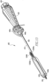
- Figs. 13-14 , 14A-14B , 15 , and 15A-15B show the delivery device 400 of the present disclosure for use with the anchor assembly 100 of Fig. 8 .
- the device 400 includes a shaft 410, a handle 420 coupled to the shaft 410, and a knob 430 coupled to the handle 420.
- the shaft 410 includes an outer member 410a and an inner member 410b slidably disposed within and coupled to the outer member 410a.
- the inner member 410b includes a distal end 410b' configured for disposal within the cannulation 310d of the insertion member 300 and a proximal end 410b" coupled to the knob 430.
- the end 410b' is of a diameter such that it engages the wall 310d' of the cannulation 310d, thereby allowing movement of the member 30 when the knob 430 is rotated, as will be further described below.
- the outer member 410a includes prongs 410c located at a distal end 410a' of the outer member 410a and a proximal end 410a" coupled to the handle 420.
- suture 440 Prior to use, suture 440 is disposed within the through hole 250 and ends 440a,440b of the suture 440 are fixed to suture holders 450 located on handle 420.
- the suture 440 helps to keep anchor 200 coupled to the shaft 410.
- the delivery device 400 and its components, especially the knob 430, is similar to the delivery device shown and described in the '869 publication.
- the ends 440a,440b of the suture 440 are also housed within channels 460 that extend along the shaft 410.
- a suture threader 12000 is also releasably coupled to the shaft 410. Threader 12000 includes a clip 12000a and a loop of suture 12000b coupled to the clip 12000a. Suture loop 12000b is disposed within the through hole 250 and placed around the clip 12000a.
- the prongs 410c are disposed within the depressions 260. Once the anchor assembly 100 is disposed within bone, the prongs 410c help to hold the anchor 200 stationary while the insertion member 300 is moved relative to the anchor 200 via rotation of the knob 430. As will be further described below, Fig. 14A shows the location of the insertion member 300 prior to fixation of suture within the through hole 250, while Fig. 15A shows the location of the insertion member 300 after fixation of suture within the through hole 250.
- the proximal end 410b" of the inner member 410b includes threads 410d on an outer surface 410e of the inner member 410b and the proximal end 410a" of the outer member 410a includes threads 410f on an inner surface 410g of the outer member 410a. Threads 410f engage threads 410d to allow for coupling of the outer and inner members 410a, 410b and axial movement of the inner member 410b relative to the outer member 410a. Axial movement of the inner member 410b relative to the outer member 410a allows for axial movement of the insertion member 300 to the two locations shown in Figs. 14A and 15A .
- Member 410b also includes a depth stop 410b′′′ that engages an end 410a′′′ of member 410a, as shown in Fig. 15B , once member 300 is located as shown in Fig. 15A . Interaction of the depth stop 410b′′′ with the end 410a′′′ ceases axial movement of the member 300 toward the through hole 250 and prevents the member 300 from being overly inserted into the cavity 230. The insertion member 300 is moved axially towards the through hole 250 to engage the flexible member and secure the flexible member within the cavity 230, which will be further described below.
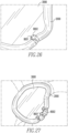
- Figs. 16-27 show the anchor assembly 10,100 of the present disclosure in use during soft tissue repair, specifically to repair labrum tears in the shoulder.
- the labrum 2000 has been torn away from the glenoid cavity 3000 and is in need of being reattached.
- Fig. 16 shows a monofilament suture loop 4001 from a suture passer 4000 being inserted through the labrum 2000 via use of a first cannula 5000.
- a grasper 6000 from a second cannula 7000 grabs the loop 4001 and pulls it through the second cannula 7000.
- the one end 8001 of the suture 8000 is pulled through the labrum 2000 and first cannula 5000 via the loop 4001, while the other end 8002 is grasped and pulled through the first cannula 5000 to have both ends 8001,8002 exiting the cannula 5000, as shown in Fig. 17 .
- a hole 3001 is then made in the glenoid 3000 via the use of a drill guide 9000 and drill 10000, as shown in Figs. 18 and 19 .
- the ends 8001,8002 are placed through the suture threader loop 11000b,12000b and pulled through the through hole 25,250 of the anchor 20,200, as shown in Figs. 20 and 21 .
- the suture 44,440 is removed from the delivery device 40,400 prior to inserting the anchor assembly 10,100 into the hole 3001.
- the suture ends 8001,8002 are tensioned and the ends 8001,8002 are locked by placing the ends 8001,8002 in the suture holder 45,450, as shown in Fig. 24 , and the inner plug 30,300 is then rotated, via rotation of the knob 43,430 to fixate the suture 8000 in the cavity 23,230.
- suture ends 8001,8002 are cut, as shown in Fig. 26 , and the delivery device 40,400 is removed. Additional anchor assemblies 10,100 may be inserted until the desired final repair is completed, as shown in Fig. 27 .
- end 8001, suture loop 12000b, and anchor assembly 100 are shown in Figs. 20-23 .
- both ends 8001,8002 are used and suture loop 11000b and anchor assembly 10 may be used rather than suture loop 12000b and anchor assembly 100.
- Figs. 28-33 show an alternative embodiment of the anchor assembly 500 of the present disclosure and its components.
- the assembly 500 includes the anchor 600 and the insertion member 700.
- the anchor 600 includes a proximal portion 610, a distal portion 620, and an inner cavity 630.
- the inner cavity 630 will be further described below.
- An opening 640 to the cavity 630 is located at the proximal portion 610 of the anchor 600.
- the anchor 600 also includes a transverse hole 650 extending through the anchor 600.
- the through hole 650 is for housing of a flexible member, such as suture. Openings 650a,b are located at each end of the through hole 650.
- the outer surface 670 of the proximal portion 610 also includes wings 680 for substantially reducing the possibility of removal of the anchor 600 when inserted into bone.
- the wings 680 are unlike barbs 28,280 in that wings 680 are longer, have more space between them, and extend further upward and outward then barbs 28,280.
- the outer surface 670 also includes at least two slots 690 extending from the openings 650a,b of the through hole 650. The slots 690 intersect the wings 680 and are configured for housing of the suture after positioning of the anchor 600 in bone.
- the cavity 630 extends into and beyond the through hole 650 and includes a non-threaded proximal portion 630a and a threaded distal portion 630b.
- the proximal portion 630a is square-shaped to correspond with an end of the delivery device used to insert the anchor 600 into bone, as will be further described below.
- the proximal portion 630a also has a larger diameter and is shorter than the distal portion 630b.
- the insertion member 700 includes a body 710 having a threaded proximal portion 710a and a non-threaded distal portion 710b.
- the proximal portion 710a has a larger diameter than the distal portion 710b.
- the member 700 includes a triangular-shaped cannulation 710e that extends a partial length of the member 700.
- the threads 710a' are configured for engagement with the threads 630c of the cavity 630 when the insertion member 700 is arranged within the cavity 630, as will be further explained below.
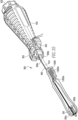
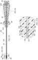
- Figs. 34, 34A , 35, 35 , 36 , 36A-36B , and 37A-37B show the delivery device 800 of the present disclosure.
- the device 800 includes a shaft 810, a handle 820 coupled to the shaft 810, and a knob 830 coupled to the handle 820.
- the shaft 810 includes an outer member 810a and an inner member 810b slidably disposed within and coupled to the outer member 810a.
- the inner member 810b includes a distal end 810b' configured for disposal within the cannulation 710e of the insertion member 700 and a proximal end 810b" coupled to the knob 830.
- the end 810b' is of a diameter such that it engages the wall 710e' of the cannulation 710e, thereby allowing movement of the member 700 when the knob 830 is rotated, as will be further described below.
- the outer member 810a includes a square-shaped tip 810c extending from a distal end 810a' of the outer member 810a and a proximal end 810a" coupled to the handle 820.
- the handle 820 includes suture holders 850, each suture holder 850 extending from a side of the handle 820. Additionally, as shown in Fig. 34 , a flexible member 900, such as a suture, is housed within the through hole 650 with each end 900a,900b of the member 900 being coupled to a holder 850. The flexible member 850 helps to hold the anchor 600 on the device 800 prior to insertion of the anchor 600 into bone. The ends 900a,900b of the suture 900 are also housed within channels 860 that extend along the shaft 810. A suture threader 13000 is also releasably coupled to the shaft 81.
- a flexible member 900 such as a suture
- Threader 13000 includes a clip 13000a and a loop of suture 13000b coupled to the clip 13000a. Suture loop 13000b is disposed within the through hole 650 and placed around the clip 13000a.
- the delivery device 800 and its components, especially the knob 830, are similar to the delivery device shown and described in the '869 publication.
- the tip 810c is disposed within the proximal portion 630a. Once the anchor assembly 500 is disposed within bone, the tip 810c helps to hold the anchor 600 stationary while the insertion member 700 is moved relative to the anchor 600. Additionally, as shown in Fig. 14A , the proximal end 810b" of the inner member 810b includes threads 810d on an outer surface 810e of the inner member 810b and the proximal end 810a" of the outer member 810a includes threads 810f on an inner surface 810g of the outer member 810a. Threads 810f engage threads 810d to allow for coupling of the outer and inner members 810a, 810b and axial movement of the inner member 810b relative to the outer member 810a.
- Member 810b also includes a depth stop 810b′′′ that engages an end 810a′′′ of member 810a, as shown in Fig. 37A , once member 700 is located as shown in Fig. 37B .
- Interaction of the depth stop 810b'" with the end 810a′′′ ceases axial movement of the member 700 toward the through hole 650 and prevents the member 700 from being overly inserted into the cavity 630.
- the insertion member 700 is moved axially towards the through hole 650 to engage the flexible member and secure the flexible member within the cavity 630, which will be further described below.
- suture from a previously placed anchor is pulled through the through hole 650.
- the manner in which the suture is pulled through the through hole 650 may be the same as the manner described in the '106 and '180 patent applications.
- the anchor assembly 500 is subsequently inserted into bone, via use of the driver 800, in the manner shown in Fig. 36B . Axial advancement of the anchor assembly 500 into the bone may occur via tapping on the handle 820.
- the insertion member 700 is moved axially towards the distal portion 630b, via rotation of the knob 830 to engage the suture and secure the suture within the cavity 630, in the manner shown in Fig. 37B .
- the anchor assembly 500 is shown in Figs. 36B and 37B .
- the components of the anchor assemblies 10,100,500 are made from a bioabsorbable polymer material via an injection molding process. However, other materials and processes may be used.
- the suture material is made from a bioabsorbable polymer material, but other material may be used.
- the outer surface 27, 270, 670 of the anchors 20,200,600 may include features other than barbs and wings 28,280,680 to reduce the possibility of removal of the anchor 20,200,600 and the barbs 28,280,680 may extend the entire length or a partial length of the anchor 20,200,600.
- the body 31,310,710 of the insertion member 30,300,700 and the cavity 23,230,630 of the anchor 20,200,600 may include features other than threads to facilitate insertion and removal of the insertion member 30,300,700 or the threads may extend a partial length of the body of the insertion member, however, these options are not part of the claimed invention.
- the threads 31a',310a,710' extend the entire length of the body 31,310,710 of the insertion member and threads may extend the entire length or a partial length of the cavity 23,230,630.
- the through hole 25,250,650 may be located anywhere along the length of the anchor 20,200,600. Additionally, it is within the scope of this disclosure for the anchor 20,200,600 to have more or less than two slots 29,290,690.
- the outer member 41a410a includes at least one prong 41c,410c and the anchor 20,200 includes at least one corresponding depression 26,260.
- the cannulation 31e,310e of the insertion member 30,300 may extend an entire length of the insertion member 30,300 and may include a shape other than triangular.
- the outer and inner members 41a,41b,410a,410b,810a,810b of the delivery device 40,400,800 include a stainless steel material, but may be made from any other metal or non-metal material that is bio-compatible and strong enough to withstand the forces that are placed on the members 41a,41b,410a,410b,810a,810b during surgery.
- the members 41a,41b,410a,410b810a,810b may be machined, die drawn and subsequently machined, or made by any other method known to one of skill in the art.
- the outer and inner members 41a, 41b,410a,410b,810a,810b are coupled to the handle 42,420,820 and knob 43,430,830 respectively, via a press-fit procedure.
- other methods of coupling the handle 42,420,820 and knob 43,430,830 to the members 41a,41b,410a,410b,810a,810b are also within the scope of this disclosure.
- the handle 42,420,820 and knob 43,430,830 are of a non-metal material, but may be made from a metal material, and both are made via an injection molding process.
- other methods of making are also within the scope of this disclosure.
- Figs. 38-40 show a first embodiment of a fenestrated suture anchor 1000 of the present disclosure.
- the anchor 1000 includes a body 1001 having a proximal portion 1001a and a distal portion 1001b, a transverse through hole 1002 located between the distal and proximal portions 1001b,1001a, and a cavity 1003 extending a partial length of the body 1001.
- Wings 1004 exist along the body 1001 and outward from it. Similar to the wings 680, wings 1004 engage bone when the anchor 1000 is inserted into the bone, as will be further described below.
- the body 1001 also includes suture slots 1005 extending from openings 1002a,1002b of the hole 1002.
- channels 1006 extending along the body 1001 on both sides of the slots 1005.
- the channels 1006 extending from an outer surface 1007 of the anchor 1000 to the cavity 1003, thereby allowing the anchor 1000 to be fenestrated.
- the channels 1006 allow for ingrowth of tissue, such as bone, and other nutrients after insertion of the anchor 1000 into bone, as will be further described later.
- a suture 1008 is housed within the hole 1002 having its ends 1008a,1008b housed within the slots 1005.
- Figs. 41-42 show a second embodiment of a fenestrated suture anchor 1100.
- the anchor 1100 includes a body 1101 having a proximal portion 1101a and a distal portion 1101b, a transverse through hole 1102 located between the distal and proximal portions 1101b,1101a, and a cavity 1103 extending a partial length of the body 1101.
- Barbs 1104 exist along the body 1101 and extend outward from it. Similar to the barbs 28,280, barbs 1104 engage bone when the anchor 1100 is inserted into the bone, as will be further described below.
- the body 1101 also includes channels 1106 extending along the body 1101.
- the channels 1106 extending from an outer surface 1107 of the anchor 1100 to the cavity 1103, thereby allowing the anchor 1100 to be fenestrated.
- the channels 1106 allow for ingrowth of tissue, such as bone, and other nutrients after insertion of the anchor 1100 into bone, as will be further described later.
- a suture 1108 is housed within the hole 1102 having its ends 1108a,1108b extend through openings 1102a,1102b and then back through the cavity 1103, as shown in Fig. 41 .
- Figs. 43-44 show a first embodiment of a fenestrated suture anchor 1200 of the present disclosure.
- the anchor 1200 includes a body 1201 having a proximal portion 1201a and a distal portion 1201b, a transverse through hole 1202 located between the distal and proximal portions 1201b,1201a, and a cavity 1203 extending a partial length of the body 1201.
- Barbs 1204 exist along the body 1201 and extend outward from it. Similar to the barbs 28,280, barbs 1204 engage bone when the anchor 1200 is inserted into the bone, as will be further described below.
- the body 1201 also includes suture slots 1205 extending from openings 1202a,1202b of the hole 1202.
- channels 1206 extending along the body 1201 interspaced with the slots 1205.
- the channels 1206 extend from an outer surface 1207 of the anchor 1200 to the cavity 1203, thereby allowing the anchor 1200 to be fenestrated.
- the channels 1206 allow for ingrowth of tissue, such as bone, and other nutrients after insertion of the anchor 1200 into bone, as will be further described later.
- a suture 1208 is housed within the hole 1202 having its ends 1208a,1208b housed within the slots 1205.
- a delivery device having a handle and a shaft may be used to deliver the anchors into bone.
- An end of the shaft may be inserted into the cavity of the anchors and may have the same shape as cavity.
- the anchors 1000,1100,1200 are designed to be inserted into bone via axial motion.
- the torn tissue may then be placed on the bone, adjacent the anchors 1000,1100,1200.
- the suture may then be pulled through the tissue and tied to attach the tissue to the bone.
- a hole may be drilled in the bone prior to inserting the anchors 1000,1100,1200 into the bone.
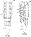
- Figs. 45-50 show anchor assemblies 1300,1400,1500 similar to the anchor assemblies 10 of Figs. 1 , 8 , and 28 .
- the anchor assemblies 1300,1400,1500 are similar to the anchor assemblies 10,100,500 of Figs. 1 , 8 , and 28 and the anchor assemblies shown and described in US Patent Application Publication No. 20090112270 , and the '869 publication mentioned above.
- Figs. 45-50 only show the anchors 1310,1410,1510 of the assemblies 1300,1400,1500.
- an insertion member similar to the insertion members shown in the above mentioned figures and publications, would also be used with the anchors 1310,1410,1510.
- the anchors 1310,1410,1510 could be used without insertion members, thereby being used in a similar manner to anchors 1000,1100,1200 during surgery.
- Figs. 45-46 show an anchor 1310 having barbs 1320 that extend outward from the body 1330 of the anchor 1310 and along its entire length on both sides.
- the barbs 1320 alternate in direction along the length of the anchor 1310. Similar to wings 680, extending the barbs 1320 outward from the body 1330 increases the overall surface area of the barbs 1320 and allows flexibility, which improves resistance to anchor pull-out, thereby reducing the possibility of removal of the anchor 1300 when inserted into bone.
- Figs. 47-50 show anchors 1410,1510, which include barbs 1420,1520, similar in design and orientation, to barbs 1320 of anchor 1310.
- the barbs 1420,1520 do not extend along the entire length of the anchor 1410,1510 and the distal end 1440,1540 of the anchor 1410,1510 is pointed thereby making it possible to insert the anchor 1410,1510 into bone without first creating a hole in the bone.
- Figs. 51 and 52 show an anchor 1610 that includes an outer body 1620 and an inner body 1630 disposed within the outer body 1620.
- the outer body 1620 includes an outer surface 1621 having wings 1622, similar to wings 680, and an inner cavity 1623.
- the distal end 1624 of the inner cavity 1623 includes a first feature 1625 and a second feature 1626, which will be more fully explained below in relation to the inner body 1630.
- the outer body 1620 also includes a transverse hole 1627 and slots 1628.
- the inner body 1630 includes a threaded inner cavity 1631, a through hole 1632, a proximal portion 1633, and a distal portion 1634.
- the inner body 1630 includes a first feature 1635 and a second feature 1636, both of which are located between the proximal and distal portions 1633,1634 and which will be more fully explained below in relation to the outer body 1620.
- the inner body 1630 is disposed within the outer body 1620 such that the outer body first feature 1625 is located within the inner body first feature 1635 and the outer body second feature 1626 is located within the inner body second feature 1636.
- the first features 1625,1635 are shaped so as to substantially reduce the possibility of the inner body 1630 rotating in relation to the outer body 1620 during repair, as will be more fully described below.
- the second features 1626,1636 are shaped so as to substantially reduce the possibility of the inner body 1630 from moving axially in relation to the outer body 1620 during insertion of the anchor 1610 into bone, as will be more fully described below. Additionally, the through holes 1627,1632 are aligned.
- anchor 1610 is part of an anchor assembly. However, for clarity purposes, the anchor 1610 is shown without an inner member. The distal portion 1634 of the inner body 1630 is pointed and the proximal portion 1633 does not extend the entire length of the inner cavity 1623, the purposes of which will be described later.
- a delivery device 1700 similar to delivery device 800, is used.
- the outer member 1710a of the shaft 1710 is shown in Figs. 51 and 52 .
- the outer member 1710a is inserted into the anchor 1610 such that the square-shaped tip 1710c is inserted into the inner cavity 1623.
- the tip 1710c engages the inner body 1630 such that there is a clearance 1800 between the distal end 1710a' of the shaft 1710 and the anchor 1610.
- the outer member 1710a only engages the inner body 1630, thereby asserting all of the axial force of the outer member 1710a on the inner body 1630, rather than the outer body 1620.
- the cooperation of the second features 1626,1636 substantially reduces the possibility of the inner body 1630 becoming unlocked from the outer body 1620 during axial insertion of the anchor 1610 into the bone.
- a threaded inner member is rotationally inserted into the cavity 1631 via the use an inner member on the delivery device 1700, similar to the method of repair described above.
- the cooperation of the first features 1625,1635 substantially reduces the possibility of rotation of the inner body 1630 in relation to the outer body 1620.
- the pointed distal portion 1634 of the inner body 1630 allows for insertion of the anchor 1610 into bone without having to create a hole in the bone prior to insertion.
- the inner body 1630 is made from a metal material and the outer body 1620 is made from a polymer material.
- the outer and inner bodies 1620,1630 are coupled to each other via an interference fit or overmolding.
- other materials and manners of coupling may be used.
- Figs. 53 and 54 show an anchor 1900 similar to the anchor 600, albeit with a distal portion 1920 that is pointed enough to allow for insertion of the anchor 1900 into bone without first creating a hole in bone.
Claims (6)
- Ankerbaugruppe (100), umfassend:einen Anker (200), der einen Hohlraum (230), eine Öffnung (240) zu dem Hohlraum (230) und ein Querdurchgangsloch (250) definiert, das sich durch den Anker (200) erstreckt, undein kopfloses Einführglied (300), das zur Anordnung in dem Ankerhohlraum (230) ausgestaltet ist, wobei das Einführglied (300) einen Körper (310) und eine Kanülierung (310e), die sich über einen Teil der Länge des Einführglieds (300) erstreckt, und ein Gewinde (310a) aufweist, das entlang einer Außenfläche des Einführglieds (300) von einem proximalen Ende zu einem distalen Ende angeordnet ist, so dass das Einführglied einen Körper (310) umfasst, der vollständig mit einem Gewinde versehen ist,wobei der Ankerhohlraum (230) ein Gewinde (230c) aufweist, das sich von der Hohlraumöffnung (240) über eine Länge des Hohlraums (230) erstreckt,wobei das Durchgangsloch (250) den Hohlraum (230) kreuzt und sich der Hohlraum (230) über das Durchgangsloch (250) hinaus erstreckt, wobei das Durchgangsloch (250) eine erste und eine zweite Öffnung an gegenüberliegenden Seiten des Hohlraums (230) definiert,wobei das Einführgliedgewinde (310a) und das Hohlraumgewinde (230c) dazu ausgestaltet sind, einander in Eingriff zu nehmen, und das Einführglied (300) in dem Hohlraum (230) beweglich ist, um die erste und die zweite Öffnung abzudecken, wenn es in einer Nahtmaterialfixierungsposition ist.
- Ankerbaugruppe (100) nach Anspruch 1, wobei die Kanülierung (31e) dreieckig ist.
- Ankerbaugruppe (100) nach Anspruch 1, wobei der Ankerhohlraum (230) einen proximalen Abschnitt (210) mit Gewinde und einen distalen Abschnitt (220) ohne Gewinde aufweist.
- Ankerbaugruppe nach Anspruch 1, wobei der Ankerhohlraum (230) einen proximalen Abschnitt (210) ohne Gewinde und einen distalen Abschnitt (220) mit Gewinde aufweist.
- Ankerbaugruppe (100) nach Anspruch 4, wobei der proximale Abschnitt (210) quadratisch ist.
- Ankerbaugruppe (100) nach Anspruch 1, wobei der Anker (200) eine Außenfläche (270) und Widerhaken (280) umfasst, die sich von dem Körper (200) erstrecken und sich in Richtung entlang der Länge des Körpers (200) abwechseln.
Applications Claiming Priority (6)
| Application Number | Priority Date | Filing Date | Title |
|---|---|---|---|
| US25973709P | 2009-11-10 | 2009-11-10 | |
| US25973909P | 2009-11-10 | 2009-11-10 | |
| US29069509P | 2009-12-29 | 2009-12-29 | |
| US31248110P | 2010-03-10 | 2010-03-10 | |
| US33422110P | 2010-05-13 | 2010-05-13 | |
| PCT/US2010/056107 WO2011059995A2 (en) | 2009-11-10 | 2010-11-10 | Tissue repair devices |
Publications (2)
| Publication Number | Publication Date |
|---|---|
| EP2498686A2 EP2498686A2 (de) | 2012-09-19 |
| EP2498686B1 true EP2498686B1 (de) | 2024-01-10 |
Family
ID=43536392
Family Applications (1)
| Application Number | Title | Priority Date | Filing Date |
|---|---|---|---|
| EP10781765.2A Active EP2498686B1 (de) | 2009-11-10 | 2010-11-10 | Vorrichtungen für gewebereparatur |
Country Status (7)
| Country | Link |
|---|---|
| US (4) | US9936939B2 (de) |
| EP (1) | EP2498686B1 (de) |
| JP (2) | JP2013510659A (de) |
| CN (1) | CN102711632B (de) |
| AU (2) | AU2010319635B2 (de) |
| RU (1) | RU2562601C2 (de) |
| WO (1) | WO2011059995A2 (de) |
Families Citing this family (81)
| Publication number | Priority date | Publication date | Assignee | Title |
|---|---|---|---|---|
| US20070005068A1 (en) * | 2005-02-07 | 2007-01-04 | Sklar Joseph H | Knotless suture anchor |
| WO2012161853A2 (en) * | 2011-05-23 | 2012-11-29 | Sklar Joseph H | Knotless suture anchor for securing soft tissue to bone |
| DE102006010116A1 (de) * | 2006-02-27 | 2007-08-30 | Karl Storz Gmbh & Co.Kg | Ankerelement zum knotenfreien Fixieren von Gewebe an einem Knochen |
| US8894661B2 (en) | 2007-08-16 | 2014-11-25 | Smith & Nephew, Inc. | Helicoil interference fixation system for attaching a graft ligament to a bone |
| WO2009055800A1 (en) * | 2007-10-25 | 2009-04-30 | Smith & Nephew, Inc. | Anchor assembly |
| AU2010315413B2 (en) | 2009-10-28 | 2016-02-18 | Smith & Nephew, Inc. | Threaded suture anchor |
| CN102711632B (zh) * | 2009-11-10 | 2015-11-25 | 史密夫和内修有限公司 | 组织修复器械 |
| US9314240B2 (en) | 2009-11-10 | 2016-04-19 | Smith & Nephew, Inc. | Locking suture anchor assembly |
| US9775702B2 (en) | 2010-03-10 | 2017-10-03 | Smith & Nephew, Inc. | Composite interference screws and drivers |
| US9579188B2 (en) | 2010-03-10 | 2017-02-28 | Smith & Nephew, Inc. | Anchor having a controlled driver orientation |
| US9308080B2 (en) | 2010-03-10 | 2016-04-12 | Smith & Nephew Inc. | Composite interference screws and drivers |
| WO2011112776A1 (en) | 2010-03-10 | 2011-09-15 | Smith & Nephew, Inc. | Composite interference screws and drivers |
| CN107126239A (zh) | 2010-09-24 | 2017-09-05 | 斯博特威尔丁股份有限公司 | 缝线锚钉和用于相对硬组织固定缝线的方法 |
| US9713463B2 (en) * | 2011-01-13 | 2017-07-25 | Howmedica Osteonics Corp | Toggle bolt assembly and method of assembly |
| RU2725095C2 (ru) | 2011-01-28 | 2020-06-29 | СпортУэлдинг ГмбХ | Фиксатор шовного материала, устройство для закрепления шовного материала в твердой ткани и хирургическое устройство, содержащее фиксатор шовного материала |
| CN103338711B (zh) | 2011-01-28 | 2017-04-05 | 斯博特威尔丁股份有限公司 | 用于将具有缝合线的缝合锚或有头锚固定到硬组织中的设备和方法 |
| EP2486856B1 (de) * | 2011-02-09 | 2014-07-09 | Arthrex, Inc. | Knochenanker für skapholunäres Rekonstruktion |
| MX344606B (es) | 2011-03-11 | 2016-12-20 | Smith & Nephew Inc | Trepano. |
| KR20140043768A (ko) * | 2011-06-07 | 2014-04-10 | 스미스 앤드 네퓨, 인크. | 외과용 앵커 전달 시스템 |
| US9636100B2 (en) * | 2011-10-03 | 2017-05-02 | Smith & Nephew, Inc. | Tissue-to-bone reattachment |
| US9084595B2 (en) * | 2011-10-19 | 2015-07-21 | Smith & Nephew Inc. | Blended shaft drive |
| US9782165B2 (en) | 2011-11-11 | 2017-10-10 | VentureMD Innovations, LLC | Transosseous attachment |
| US10548585B2 (en) | 2011-11-16 | 2020-02-04 | VentureMD Innovations, LLC | Soft tissue attachment |
| US10136883B2 (en) | 2011-11-16 | 2018-11-27 | VentureMD Innovations, LLC | Method of anchoring a suture |
| US10675014B2 (en) | 2011-11-16 | 2020-06-09 | Crossroads Extremity Systems, Llc | Knotless soft tissue attachment |
| US10470756B2 (en) | 2011-11-16 | 2019-11-12 | VentureMD Innovations, LLC | Suture anchor and method |
| EP2596758A1 (de) * | 2011-11-24 | 2013-05-29 | Sysorb GmbH | Knochenschraube |
| EP2599449B1 (de) * | 2011-11-29 | 2015-02-25 | Arthrex, Inc. | Applikator für Naht/Knopf-Element mit eindeutiger Verbindung und Steuerung |
| IN2014DN10018A (de) * | 2012-05-29 | 2015-08-14 | Smith & Nephew Inc | |
| EP2877105A1 (de) * | 2012-07-26 | 2015-06-03 | Smith&Nephew, Inc. | Knotenloser knochenanker für instabilitätsreparatur |
| US9687221B2 (en) | 2013-02-13 | 2017-06-27 | Venture MD Innovations, LLC | Method of anchoring a suture |
| JP6382237B2 (ja) | 2013-03-06 | 2018-08-29 | スミス アンド ネフュー インコーポレーテッドSmith & Nephew,Inc. | マイクロアンカー |
| US20140257026A1 (en) * | 2013-03-08 | 2014-09-11 | Boston Scientific Scimed, Inc. | Adjustable implants and methods of implanting the same |
| US9155531B2 (en) | 2013-03-15 | 2015-10-13 | Smith & Nephew, Inc. | Miniaturized dual drive open architecture suture anchor |
| US9526488B2 (en) * | 2013-03-15 | 2016-12-27 | Smith & Nephew, Inc. | Fenestrated locking suture anchor assembly |
| WO2014169058A1 (en) | 2013-04-09 | 2014-10-16 | Smith & Nephew, Inc | Open-architecture interference screw |
| WO2014201128A1 (en) * | 2013-06-11 | 2014-12-18 | Smith & Nephew, Inc. | Robust open-architecture bone anchor |
| CN104665905B (zh) | 2013-11-26 | 2018-04-06 | 财团法人工业技术研究院 | 仿生固定装置 |
| CN104665913B (zh) * | 2013-11-26 | 2017-06-06 | 财团法人工业技术研究院 | 仿生固定装置与其拔出装置 |
| CN104665906B (zh) | 2013-11-26 | 2017-09-08 | 财团法人工业技术研究院 | 仿生固定装置 |
| RU2679084C2 (ru) * | 2014-01-10 | 2019-02-05 | Конинклейке Филипс Н.В. | Устройство манипулирования языком, костный якорь для использования в таких устройствах, устройство управления и способ регулировки |
| WO2015127057A1 (en) * | 2014-02-20 | 2015-08-27 | Smith & Nephew, Inc. | Hollow suture anchor and driver |
| JP6433673B2 (ja) * | 2014-04-02 | 2018-12-05 | オリンパステルモバイオマテリアル株式会社 | アンカー締結具および締結ユニット |
| WO2016111856A1 (en) * | 2015-01-06 | 2016-07-14 | Smith & Nephew, Inc. | Knotless suture or tissue anchor and method |
| WO2016186854A1 (en) * | 2015-05-21 | 2016-11-24 | Smith & Nephew, Inc. | Suture anchor system with slotted suture anchor |
| JP6542917B2 (ja) * | 2015-06-30 | 2019-07-10 | スミス アンド ネフュー インコーポレイテッド | ねじ式プラグを有する縫合糸アンカーシステム |
| CN106333719B (zh) | 2015-07-07 | 2020-06-26 | 爱彼医疗有限公司 | 用于缝合的设备和方法 |
| US10820918B2 (en) | 2015-07-17 | 2020-11-03 | Crossroads Extremity Systems, Llc | Transosseous guide and method |
| US10154868B2 (en) | 2015-07-17 | 2018-12-18 | Kator, Llc | Transosseous method |
| US9962174B2 (en) | 2015-07-17 | 2018-05-08 | Kator, Llc | Transosseous method |
| US10143462B2 (en) | 2015-08-04 | 2018-12-04 | Kator, Llc | Transosseous suture anchor method |
| WO2017062300A1 (en) * | 2015-10-08 | 2017-04-13 | Smith & Nephew, Inc. | Apparatus and method for joint repair |
| US9924935B2 (en) * | 2015-10-23 | 2018-03-27 | Smith & Nephew, Inc. | Suture anchor assembly with slip fit tip |
| US10349996B2 (en) | 2015-12-07 | 2019-07-16 | Cable Fix LLC | Apparatus, system, and method for securing a tensioned cable through or around bone |
| TWI587847B (zh) | 2015-12-07 | 2017-06-21 | 財團法人工業技術研究院 | 骨整合植入元件 |
| KR20230104750A (ko) * | 2015-12-16 | 2023-07-10 | 콘메드 코포레이션 | 매듭없는 봉합사 앵커 및 전개 장치 |
| US10363026B2 (en) * | 2016-02-12 | 2019-07-30 | Fusion Orthopedics, Llc | Rotating suture anchor |
| EP3413805A1 (de) * | 2016-02-12 | 2018-12-19 | Smith & Nephew, Inc | Nahtanker mit verformbarer kappe |
| US10390936B2 (en) | 2016-05-25 | 2019-08-27 | Medos International Sarl | Overdrive prevention for expandable anchor |
| US10426460B2 (en) | 2016-07-05 | 2019-10-01 | Mortise Medical, LLC | Compression and tension instruments and methods of use to reinforce ligaments |
| US10624734B2 (en) * | 2016-10-18 | 2020-04-21 | Arthrex, Inc. | Surgical assembly for tissue repair |
| WO2018118931A1 (en) * | 2016-12-21 | 2018-06-28 | Wright Medical Technology, Inc. | Syndesmosis construct |
| KR101815589B1 (ko) * | 2017-02-09 | 2018-01-05 | (주)오스테오닉 | 측부 개방형 봉합사 앵커 |
| US10245020B2 (en) * | 2017-03-13 | 2019-04-02 | Medos International Sarl | Methods and systems for knotless suture anchoring |
| US10368857B2 (en) | 2017-03-13 | 2019-08-06 | Medos International Sarl | Methods and devices for knotless suture anchoring |
| US10639026B2 (en) | 2017-07-27 | 2020-05-05 | Medos International Sarl | Knotless suture anchoring using two awl shafts |
| US10786236B2 (en) * | 2017-08-04 | 2020-09-29 | Tigon Medical | Knotless anchor |
| US10925654B2 (en) | 2017-09-19 | 2021-02-23 | Cable Fix LLC | Apparatus, system, and method for crimping a cable for bone fixation |
| US10179016B1 (en) * | 2017-09-19 | 2019-01-15 | Cable Fix LLC | Apparatus, system, and method for crimping a cable for bone fixation |
| CN108577911A (zh) * | 2018-05-22 | 2018-09-28 | 黄建明 | 一种用于固定高强度缝线的铆钉装置 |
| TWI684436B (zh) * | 2018-12-11 | 2020-02-11 | 高雄醫學大學 | 十字韌帶懸吊內鎖式固定器 |
| CN109498216A (zh) * | 2018-12-25 | 2019-03-22 | 乐普(北京)医疗器械股份有限公司 | 一种用于瓣膜修复的牵拉线锁定导管 |
| CA3126935A1 (en) * | 2019-01-16 | 2020-07-23 | Neochord, Inc. | Transcatheter methods for heart valve repair |
| EP3689259B1 (de) * | 2019-02-04 | 2023-10-18 | Smith & Nephew, Inc. | Suture anchor montages |
| EP4051131A1 (de) * | 2019-10-31 | 2022-09-07 | Smith&Nephew, Inc. | Healicoil knotenlose distale spitze und stopfenübertragung |
| AU2021201202A1 (en) * | 2020-03-23 | 2021-10-07 | Smith & Nephew Asia Pacific Pte. Limited | Anchor delivery systems |
| CA3183696A1 (en) * | 2020-06-02 | 2021-12-09 | Conmed Corporation | Self-punching lateral row anchor and anchor driver |
| CN111803159A (zh) * | 2020-06-11 | 2020-10-23 | 河北春立航诺新材料科技有限公司 | 带线骨水泥锚钉及手柄 |
| US11653952B2 (en) * | 2020-09-15 | 2023-05-23 | Bret G. Ball | Method and apparatus for improving bone screw implants |
| US20220167962A1 (en) * | 2020-12-01 | 2022-06-02 | Dunamis Medical Technologies, Llc | Re-Tensionable Suture Anchor System and Related Methods |
| WO2024073484A1 (en) * | 2022-09-28 | 2024-04-04 | Biomedtrix, Llc | Orthopedic bone screw |
Citations (4)
| Publication number | Priority date | Publication date | Assignee | Title |
|---|---|---|---|---|
| US5258016A (en) * | 1990-07-13 | 1993-11-02 | American Cyanamid Company | Suture anchor and driver assembly |
| WO2000035388A1 (en) * | 1998-12-14 | 2000-06-22 | Phoenix Biomedical Corp. | System for stabilizing the vertebral column including deployment instruments and variable expansion inserts therefor |
| WO2001030253A1 (en) * | 1999-10-26 | 2001-05-03 | Dr S. Fine & Dr G. Shar Pty Ltd | Orthopaedic ligament fixation system |
| WO2006060035A2 (en) * | 2004-06-02 | 2006-06-08 | Kfx Medical Corporation | System and method for attaching soft tissue to bone |
Family Cites Families (188)
| Publication number | Priority date | Publication date | Assignee | Title |
|---|---|---|---|---|
| US318125A (en) * | 1885-05-19 | Door-hanger | ||
| US254473A (en) | 1882-03-07 | Rope-clamp | ||
| US3187620A (en) * | 1962-03-16 | 1965-06-08 | Fischer Artur | Expansion anchor with rotationpreventing teeth |
| US3268965A (en) | 1964-05-11 | 1966-08-30 | Lisle Corp | Cable clamp |
| US4750492A (en) | 1985-02-27 | 1988-06-14 | Richards Medical Company | Absorbable suture apparatus, method and installer |
| US4636121A (en) * | 1985-04-22 | 1987-01-13 | Miller Lillias S | Holding screw |
| US4738255A (en) | 1986-04-07 | 1988-04-19 | Biotron Labs, Inc. | Suture anchor system |
| SU1620104A1 (ru) * | 1988-08-10 | 1991-01-15 | Запорожский Областной Отдел Здравоохранения | Винт дл остеосинтеза |
| US4870957A (en) | 1988-12-27 | 1989-10-03 | Marlowe Goble E | Ligament anchor system |
| US4927421A (en) | 1989-05-15 | 1990-05-22 | Marlowe Goble E | Process of endosteal fixation of a ligament |
| US5102421A (en) * | 1990-06-14 | 1992-04-07 | Wm. E. Anpach, III | Suture anchor and method of forming |
| US5037422A (en) * | 1990-07-02 | 1991-08-06 | Acufex Microsurgical, Inc. | Bone anchor and method of anchoring a suture to a bone |
| US5100417A (en) * | 1990-07-13 | 1992-03-31 | American Cyanamid Company | Suture anchor and driver assembly |
| EP0465910B1 (de) | 1990-07-13 | 1995-11-08 | American Cyanamid Company | Nähfadenanker und Installierwerkzeug |
| US5725529A (en) | 1990-09-25 | 1998-03-10 | Innovasive Devices, Inc. | Bone fastener |
| AU653752B2 (en) | 1990-09-25 | 1994-10-13 | Ethicon Inc. | Bone fastener |
| US5152790A (en) | 1991-03-21 | 1992-10-06 | American Cyanamid Company | Ligament reconstruction graft anchor apparatus |
| US5354298A (en) | 1991-03-22 | 1994-10-11 | United States Surgical Corporation | Suture anchor installation system |
| US5480403A (en) | 1991-03-22 | 1996-01-02 | United States Surgical Corporation | Suture anchoring device and method |
| FR2676356A1 (fr) * | 1991-05-13 | 1992-11-20 | Cendis Medical | Element de fixation pour ligaments. |
| US5141520A (en) * | 1991-10-29 | 1992-08-25 | Marlowe Goble E | Harpoon suture anchor |
| US5156616A (en) | 1992-02-10 | 1992-10-20 | Meadows Bruce F | Apparatus and method for suture attachment |
| US5176682A (en) | 1992-06-01 | 1993-01-05 | Chow James C Y | Surgical implement |
| US5383905A (en) | 1992-10-09 | 1995-01-24 | United States Surgical Corporation | Suture loop locking device |
| EP0596177B1 (de) * | 1992-11-02 | 1998-01-07 | Sulzer Orthopädie AG | Verankerung für ein künstliches Band, insbesondere ein Kreuzband eines Kniegelenks |
| FR2704132B1 (fr) * | 1993-04-23 | 1995-07-13 | Ethnor | Système pour ligature et/ou suture pour chirurgie endoscopique. |
| US5423860A (en) | 1993-05-28 | 1995-06-13 | American Cyanamid Company | Protective carrier for suture anchor |
| US5505735A (en) * | 1993-06-10 | 1996-04-09 | Mitek Surgical Products, Inc. | Surgical anchor and method for using the same |
| US5370662A (en) | 1993-06-23 | 1994-12-06 | Kevin R. Stone | Suture anchor assembly |
| US5500000A (en) * | 1993-07-01 | 1996-03-19 | United States Surgical Corporation | Soft tissue repair system and method |
| US5584835A (en) * | 1993-10-18 | 1996-12-17 | Greenfield; Jon B. | Soft tissue to bone fixation device and method |
| US5545180A (en) | 1993-12-13 | 1996-08-13 | Ethicon, Inc. | Umbrella-shaped suture anchor device with actuating ring member |
| USRE36289E (en) | 1993-12-13 | 1999-08-31 | Ethicon, Inc. | Umbrella shaped suture anchor device with actuating ring member |
| US5527342A (en) | 1993-12-14 | 1996-06-18 | Pietrzak; William S. | Method and apparatus for securing soft tissues, tendons and ligaments to bone |
| US5522843A (en) * | 1994-02-23 | 1996-06-04 | Orthopaedic Biosystems Limited, Inc. | Apparatus for attaching soft tissue to bone |
| US5486197A (en) | 1994-03-24 | 1996-01-23 | Ethicon, Inc. | Two-piece suture anchor with barbs |
| US5458601A (en) | 1994-03-28 | 1995-10-17 | Medical University Of South Carolina | Adjustable ligament anchor |
| US5630824A (en) | 1994-06-01 | 1997-05-20 | Innovasive Devices, Inc. | Suture attachment device |
| US5464427A (en) * | 1994-10-04 | 1995-11-07 | Synthes (U.S.A.) | Expanding suture anchor |
| US5649963A (en) | 1994-11-10 | 1997-07-22 | Innovasive Devices, Inc. | Suture anchor assembly and methods |
| US5607432A (en) | 1995-01-23 | 1997-03-04 | Linvatec Corporation | Threaded suture anchor retriever |
| FR2730158B1 (fr) | 1995-02-06 | 1999-11-26 | Jbs Sa | Dispositif de maintien d'un ecartement normal entre les vertebres et destine au remplacement de vertebres manquantes |
| US5584860A (en) | 1995-02-15 | 1996-12-17 | Mitek Surgical Products, Inc. | Suture anchor loader and driver |
| US5569306A (en) | 1995-06-06 | 1996-10-29 | Thal; Raymond | Knotless suture anchor assembly |
| CA2219089C (en) | 1995-06-06 | 2001-05-08 | Raymond Thal | Knotless suture anchor assembly |
| US6086608A (en) * | 1996-02-22 | 2000-07-11 | Smith & Nephew, Inc. | Suture collet |
| US5904704A (en) | 1995-08-14 | 1999-05-18 | Mitek Surgical Products, Inc. | Suture anchor assembly |
| US5782865A (en) | 1995-08-25 | 1998-07-21 | Grotz; Robert Thomas | Stabilizer for human joints |
| BR9707531A (pt) | 1996-02-16 | 1999-07-27 | Smith & Nephew Inc | ancora de enxerto |
| US5957953A (en) * | 1996-02-16 | 1999-09-28 | Smith & Nephew, Inc. | Expandable suture anchor |
| US5702397A (en) * | 1996-02-20 | 1997-12-30 | Medicinelodge, Inc. | Ligament bone anchor and method for its use |
| US6013083A (en) | 1997-05-02 | 2000-01-11 | Bennett; William F. | Arthroscopic rotator cuff repair apparatus and method |
| US5849004A (en) * | 1996-07-17 | 1998-12-15 | Bramlet; Dale G. | Surgical anchor |
| US6117162A (en) | 1996-08-05 | 2000-09-12 | Arthrex, Inc. | Corkscrew suture anchor |
| FR2753368B1 (fr) | 1996-09-13 | 1999-01-08 | Chauvin Jean Luc | Cage d'osteosynthese expansive |
| US5733307A (en) | 1996-09-17 | 1998-03-31 | Amei Technologies, Inc. | Bone anchor having a suture trough |
| US5948000A (en) | 1996-10-03 | 1999-09-07 | United States Surgical Corporation | System for suture anchor placement |
| US5948001A (en) | 1996-10-03 | 1999-09-07 | United States Surgical Corporation | System for suture anchor placement |
| US5827291A (en) | 1996-11-05 | 1998-10-27 | Linvatec Corporation | Suture anchor driver with suture retainer |
| EP1419747B1 (de) | 1996-11-21 | 2015-04-01 | Ethicon, Inc. | Vorrichtung zur befestigung von körpereigenen oder künstlichen sehnentransplantaten in knochen |
| US6533816B2 (en) | 1999-02-09 | 2003-03-18 | Joseph H. Sklar | Graft ligament anchor and method for attaching a graft ligament to a bone |
| US6436124B1 (en) | 1996-12-19 | 2002-08-20 | Bionx Implants Oy | Suture anchor |
| US5707395A (en) * | 1997-01-16 | 1998-01-13 | Li Medical Technologies, Inc. | Surgical fastener and method and apparatus for ligament repair |
| DE69816306T2 (de) | 1997-02-13 | 2004-05-27 | Boston Scientific Ltd., St. Michael | Dilatator für minimal invasive beckenchirurgie |
| US5935129A (en) | 1997-03-07 | 1999-08-10 | Innovasive Devices, Inc. | Methods and apparatus for anchoring objects to bone |
| US6692499B2 (en) * | 1997-07-02 | 2004-02-17 | Linvatec Biomaterials Oy | Surgical fastener for tissue treatment |
| US6010525A (en) * | 1997-08-01 | 2000-01-04 | Peter M. Bonutti | Method and apparatus for securing a suture |
| US6149669A (en) | 1997-10-30 | 2000-11-21 | Li Medical Technologies, Inc. | Surgical fastener assembly method of use |
| DE19801219A1 (de) * | 1998-01-15 | 1999-07-22 | Holger K Dr Essiger | Knochennagel |
| CA2341232C (en) * | 1998-08-21 | 2007-06-26 | Synthes (U.S.A.) | Self-cutting hollow cylindrical bone anchoring element |
| US6146387A (en) * | 1998-08-26 | 2000-11-14 | Linvatec Corporation | Cannulated tissue anchor system |
| US6200329B1 (en) | 1998-08-31 | 2001-03-13 | Smith & Nephew, Inc. | Suture collet |
| FR2782913B1 (fr) | 1998-09-04 | 2000-11-10 | Perice Ramon Viladot | Implant pour pied plat |
| US6165203A (en) * | 1998-09-11 | 2000-12-26 | Bio Innovation, Ltd. | Suture anchor installation devices and methods |
| US6368326B1 (en) | 1998-09-28 | 2002-04-09 | Daos Limited | Internal cord fixation device |
| US6200330B1 (en) | 1998-11-23 | 2001-03-13 | Theodore V. Benderev | Systems for securing sutures, grafts and soft tissue to bone and periosteum |
| ATE324072T1 (de) | 1998-12-30 | 2006-05-15 | Ethicon Inc | Fadensicherungsgerät |
| US8343186B2 (en) | 2004-04-06 | 2013-01-01 | Arthrex, Inc. | Fully threaded suture anchor with transverse anchor pin |
| US6228096B1 (en) | 1999-03-31 | 2001-05-08 | Sam R. Marchand | Instrument and method for manipulating an operating member coupled to suture material while maintaining tension on the suture material |
| US6267766B1 (en) | 1999-05-28 | 2001-07-31 | Stephen S. Burkhart | Suture anchor reel device kit and method |
| US6214007B1 (en) * | 1999-06-01 | 2001-04-10 | David G. Anderson | Surgical fastener for fixation of a soft tissue graft to a bone tunnel |
| US6152934A (en) | 1999-06-14 | 2000-11-28 | Ethicon Endo-Surgery, Inc. | Surgical knot tying instrument |
| US6319252B1 (en) | 1999-07-23 | 2001-11-20 | Mcdevitt Dennis | System and method for attaching soft tissue to bone |
| US6517542B1 (en) * | 1999-08-04 | 2003-02-11 | The Cleveland Clinic Foundation | Bone anchoring system |
| US6527794B1 (en) | 1999-08-10 | 2003-03-04 | Ethicon, Inc. | Self-locking suture anchor |
| US6736829B1 (en) | 1999-11-11 | 2004-05-18 | Linvatec Corporation | Toggle anchor and tool for insertion thereof |
| US6159235A (en) * | 1999-12-21 | 2000-12-12 | Kim; Andrew C. | Selflock anchor screw |
| US6524317B1 (en) | 1999-12-30 | 2003-02-25 | Opus Medical, Inc. | Method and apparatus for attaching connective tissues to bone using a knotless suture anchoring device |
| DE20000777U1 (de) | 2000-01-18 | 2001-06-07 | Tehalit Gmbh | Geräteeinbaudose für Leitungsführungskanäle |
| US6287324B1 (en) * | 2000-01-28 | 2001-09-11 | Shoulderon Ltd. | Self-drilling surgical suture anchor |
| US20040088004A1 (en) | 2000-03-13 | 2004-05-06 | Rosch Theodor Gerhard | Suture anchor |
| DE20007777U1 (de) * | 2000-04-29 | 2000-07-06 | Aesculap Ag & Co Kg | Faden-Anker-System zum Verbinden von Gewebeteilen und Instrument zum Einsetzen eines Ankerimplantats |
| US7329272B2 (en) | 2000-06-22 | 2008-02-12 | Arthrex, Inc. | Graft fixation using a plug against suture |
| WO2001097677A2 (en) | 2000-06-22 | 2001-12-27 | Arthrex, Inc. | Graft fixation using a screw or plug against suture or tissue |
| US7993369B2 (en) | 2000-06-22 | 2011-08-09 | Arthrex, Inc. | Graft fixation using a plug against suture |
| US6585730B1 (en) | 2000-08-30 | 2003-07-01 | Opus Medical, Inc. | Method and apparatus for attaching connective tissues to bone using a knotless suture anchoring device |
| US6569186B1 (en) * | 2000-10-05 | 2003-05-27 | Biomet, Inc. | Soft tissue screw and fixation device |
| AU2001296789A1 (en) | 2000-10-17 | 2002-04-29 | Coapt Systems, Inc. | Intraosseous soft tissue-to-bone anchor |
| US6641596B1 (en) * | 2000-10-18 | 2003-11-04 | Ethicon, Inc. | Knotless bioabsorbable suture anchor system and method |
| US6656185B2 (en) | 2000-10-24 | 2003-12-02 | Spineology Inc. | Tension band clip |
| US6520980B1 (en) | 2000-11-02 | 2003-02-18 | Opus Medical, Inc. | Method and apparatus for attaching connective tissues to bone using a self-locking knotless suture anchoring device |
| US6692516B2 (en) * | 2000-11-28 | 2004-02-17 | Linvatec Corporation | Knotless suture anchor and method for knotlessly securing tissue |
| US6840953B2 (en) | 2000-12-22 | 2005-01-11 | United States Surgical Corporation | Suture screw |
| US7083638B2 (en) * | 2001-02-12 | 2006-08-01 | Arthrocare Corporation | Method and apparatus for attaching connective tissues to bone using a knotless suture anchoring device |
| US6508830B2 (en) | 2001-04-30 | 2003-01-21 | Musculoskeletal Transplant Foundation | Suture anchor |
| US20020188301A1 (en) | 2001-06-11 | 2002-12-12 | Dallara Mark Douglas | Tissue anchor insertion system |
| US6887271B2 (en) * | 2001-09-28 | 2005-05-03 | Ethicon, Inc. | Expanding ligament graft fixation system and method |
| US6652563B2 (en) | 2001-10-02 | 2003-11-25 | Arthrex, Inc. | Suture anchor with internal suture loop |
| US7491217B1 (en) * | 2001-10-16 | 2009-02-17 | Hendren Ronald D | Graft anchoring device |
| US6783527B2 (en) * | 2001-10-30 | 2004-08-31 | Sdgi Holdings, Inc. | Flexible spinal stabilization system and method |
| US6695852B2 (en) * | 2001-10-31 | 2004-02-24 | Spineology, Inc. | Tension tools for tension band clip |
| US6986781B2 (en) | 2001-11-08 | 2006-01-17 | Smith & Nephew, Inc. | Tissue repair system |
| US6780198B1 (en) | 2001-12-06 | 2004-08-24 | Opus Medical, Inc. | Bone anchor insertion device |
| US6746457B2 (en) * | 2001-12-07 | 2004-06-08 | Abbott Laboratories | Snared suture trimmer |
| US7022129B2 (en) | 2002-03-29 | 2006-04-04 | Ethicon, Inc. | Threaded cable anchor |
| US7326222B2 (en) | 2002-05-01 | 2008-02-05 | Arthrex, Inc. | Suture tensioning device |
| US7416556B2 (en) | 2002-06-06 | 2008-08-26 | Abbott Laboratories | Stop-cock suture clamping system |
| US20040068262A1 (en) | 2002-10-02 | 2004-04-08 | Mark Lemos | Soft tissue fixation implant |
| US7713286B2 (en) | 2002-11-15 | 2010-05-11 | Linvatec Corporation | Knotless suture anchor |
| US7090690B2 (en) * | 2002-11-19 | 2006-08-15 | Arthrocare Corporation | Devices and methods for repairing soft tissue |
| US7776042B2 (en) | 2002-12-03 | 2010-08-17 | Trans1 Inc. | Methods and apparatus for provision of therapy to adjacent motion segments |
| US7517357B2 (en) | 2003-01-09 | 2009-04-14 | Linvatec Biomaterials | Knotless suture anchor |
| US20040138707A1 (en) | 2003-01-14 | 2004-07-15 | Greenhalgh E. Skott | Anchor removable from a substrate |
| US7473267B2 (en) | 2003-04-25 | 2009-01-06 | Warsaw Orthopedic, Inc. | System and method for minimally invasive posterior fixation |
| US7322999B2 (en) | 2003-05-09 | 2008-01-29 | Atrion Medical Products, Inc. | Tissue punch and method for creating an anastomosis for locating a bypass graft |
| US8267981B2 (en) | 2003-06-10 | 2012-09-18 | Depuy Mitek, Inc. | Suture anchor with improved drive head |
| US7309355B2 (en) * | 2003-06-27 | 2007-12-18 | Depuy Mitek, Inc. | Flexible tibial sheath |
| US7468064B2 (en) | 2003-08-21 | 2008-12-23 | Warsaw Orthopedic, Inc. | Systems and methods for positioning implants relative to bone anchors in surgical approaches to the spine |
| US7837710B2 (en) * | 2003-09-10 | 2010-11-23 | Linvatec Corporation | Knotless suture anchor |
| DK1662971T3 (da) | 2003-09-15 | 2011-08-29 | Allergan Inc | Fastgørelsessystem til en implanterbar indretning |
| US7678134B2 (en) | 2003-10-10 | 2010-03-16 | Arthrex, Inc. | Knotless anchor for tissue repair |
| US7217279B2 (en) * | 2003-11-14 | 2007-05-15 | Ethicon, Inc. | Suture loop anchor |
| DE102004009429A1 (de) * | 2004-02-24 | 2005-09-22 | Biedermann Motech Gmbh | Knochenverankerungselement |
| DE202004004844U1 (de) | 2004-03-27 | 2004-05-27 | Richard Martin Medizintechnik Gmbh | Schraubendreher für Knochenschrauben |
| US20060282081A1 (en) * | 2004-04-16 | 2006-12-14 | Fanton Gary S | Apparatus and method for securing tissue to bone with a suture |
| US20050245932A1 (en) * | 2004-04-16 | 2005-11-03 | Fanton Gary S | Apparatus and methods for securing tissue to bone |
| US7367584B2 (en) | 2004-04-19 | 2008-05-06 | Automotive Systems Laboratory, Inc. | Gas generating system |
| US8062334B2 (en) * | 2004-06-02 | 2011-11-22 | Kfx Medical Corporation | Suture anchor |
| US7322978B2 (en) * | 2004-06-22 | 2008-01-29 | Hs West Investments, Llc | Bone anchors for use in attaching soft tissue to a bone |
| US7651502B2 (en) * | 2004-09-24 | 2010-01-26 | Jackson Roger P | Spinal fixation tool set and method for rod reduction and fastener insertion |
| AU2005290341B2 (en) * | 2004-09-28 | 2012-01-19 | Surgical Solutions Llc | Suture anchor |
| US20060079904A1 (en) | 2004-10-13 | 2006-04-13 | Raymond Thal | Multirow knotless suture anchor assembly |
| US8986345B2 (en) | 2004-12-07 | 2015-03-24 | Biomet Sports Medicine, Llc | Expanding suture anchor having an actuator pin |
| JP2008528110A (ja) * | 2005-01-21 | 2008-07-31 | メディシンロッジ インコーポレイテッド | 滑車溝インプラントならびに関連の方法および器具 |
| US20070005068A1 (en) * | 2005-02-07 | 2007-01-04 | Sklar Joseph H | Knotless suture anchor |
| US20080208253A1 (en) * | 2006-05-18 | 2008-08-28 | Dreyfuss Peter J | Self-punching swivel anchor and method for knotless fixation of tissue |
| DE102005021885A1 (de) * | 2005-05-04 | 2006-11-16 | Karl Storz Gmbh & Co. Kg | Vorrichtung zum Einbringen eines Ankerelements samt Faden in einen Knochen |
| US20060271060A1 (en) * | 2005-05-26 | 2006-11-30 | Arthrocare Corporation | Threaded knotless suture anchoring device and method |
| US8197509B2 (en) * | 2005-06-29 | 2012-06-12 | Depuy Mitek, Inc. | Suture anchor with improved torsional drive head |
| KR101145415B1 (ko) * | 2005-07-08 | 2012-05-15 | 비이더만 모테크 게엠베하 & 코. 카게 | 뼈 고정 요소 |
| ES2304652T3 (es) * | 2005-07-08 | 2008-10-16 | Biedermann Motech Gmbh | Elemento de anclaje para huesos. |
| DE102005044445A1 (de) | 2005-09-09 | 2007-03-22 | Aesculap Ag & Co. Kg | Schraubendreher für Knochenschrauben |
| US20070167950A1 (en) * | 2005-12-22 | 2007-07-19 | Tauro Joseph C | System and method for attaching soft tissue to bone |
| EP2465473B1 (de) * | 2005-12-22 | 2014-06-25 | Hugh S. West Jr. | Knochenanker mit verbessertem Gewinde zur Fixierung im Kortikal- und Spongiosaknochengewebe |
| GB2434541B (en) * | 2006-01-30 | 2009-06-17 | Mailling Wright Products Ltd | Method of preparing a medical restraint |
| DE102006010116A1 (de) * | 2006-02-27 | 2007-08-30 | Karl Storz Gmbh & Co.Kg | Ankerelement zum knotenfreien Fixieren von Gewebe an einem Knochen |
| US20080009904A1 (en) | 2006-03-17 | 2008-01-10 | Bourque Barnard J | Soft Tissue Fixation |
| EP1836996A1 (de) * | 2006-03-20 | 2007-09-26 | Inion Oy | Implantat zur Befestigung eines flexiblen Teiles an Knochen |
| US8758405B2 (en) | 2006-03-23 | 2014-06-24 | Ethicon Endo-Surgery, Inc | Suture tensioning device |
| WO2007134248A1 (en) | 2006-05-12 | 2007-11-22 | Cordis Corporation | Bone anchor system and method of use |
| US20080009900A1 (en) * | 2006-06-12 | 2008-01-10 | Kfx Medical Corporation | Surgical grasping device |
| AU2007275351B2 (en) * | 2006-07-20 | 2013-10-24 | Lee D. Kaplan | Surgical instruments |
| US8202295B2 (en) * | 2006-07-20 | 2012-06-19 | Kaplan Lee D | Surgical instruments |
| US8133258B2 (en) * | 2006-08-03 | 2012-03-13 | Arthrocare Corporation | Method and apparatus for attaching connective tissues to bone using a knotless suture anchoring device |
| US9750492B2 (en) | 2006-08-04 | 2017-09-05 | Depuy Mitek, Llc | Suture anchor system with tension relief mechanism |
| US9788825B2 (en) * | 2006-08-04 | 2017-10-17 | Depuy Mitek, Llc | Suture anchor with relief mechanism |
| US7674276B2 (en) * | 2006-10-06 | 2010-03-09 | Biomet Sports Medicine, Llc | Rotational securing of a suture |
| WO2008054814A2 (en) | 2006-10-31 | 2008-05-08 | Core Essence Orthopaedics, Llc | A medical device and procedure for attaching tissue to bone |
| WO2008063915A2 (en) * | 2006-11-13 | 2008-05-29 | Kfx Medical Corporation | System and method for attaching soft tissue to bone |
| WO2008109087A1 (en) * | 2007-03-05 | 2008-09-12 | C2M Medical, Inc. | Tack anchor systems, bone anchor systems,and method of use |
| US8137381B2 (en) * | 2007-04-25 | 2012-03-20 | Arthrocare Corporation | Knotless suture anchor having discrete polymer components and related methods |
| US7931660B2 (en) | 2007-05-10 | 2011-04-26 | Tyco Healthcare Group Lp | Powered tacker instrument |
| US7604640B2 (en) | 2007-06-14 | 2009-10-20 | Zimmer Spine Austin, Inc. | Device and system for applying rotary impact |
| US8196121B2 (en) * | 2007-08-23 | 2012-06-05 | International Business Machines Corporation | Modular integration of distinct type systems for the compilation of programs |
| US8197511B2 (en) * | 2007-09-24 | 2012-06-12 | Miller M Todd | Suture anchor having a suture engaging structure and inserter arrangement |
| WO2009055800A1 (en) * | 2007-10-25 | 2009-04-30 | Smith & Nephew, Inc. | Anchor assembly |
| US8454654B2 (en) * | 2007-12-13 | 2013-06-04 | Smith & Nephew, Inc. | Anchoring system |
| DE102008016607B4 (de) * | 2007-12-27 | 2020-10-29 | Mathys Ag Bettlach | Vorrichtung zur Implantation in einen Knochen und ein System für eine Beanspruchung eines rekonstruierten vorderen Kreuzbands während der Heilungsphase aufweisend die Vorrichtung |
| US9295460B2 (en) * | 2007-12-31 | 2016-03-29 | Cayenne Medical, Inc. | Anchors and method for securing suture to bone |
| US8162978B2 (en) * | 2008-03-25 | 2012-04-24 | Linvatec Corporation | Non-metallic knotless suture anchor |
| US9277910B2 (en) * | 2008-06-16 | 2016-03-08 | Cayenne Medical, Inc. | Anchors and methods for securing suture to bone |
| US8202297B2 (en) | 2008-06-19 | 2012-06-19 | Arthrex, Inc. | Technique for tissue fixation by reeling in and anchoring suture attached to tissue |
| US20090326545A1 (en) * | 2008-06-26 | 2009-12-31 | Amedica Corporation | Systems and methods for inserting a bone anchor without a pilot hole |
| CN102098969B (zh) | 2008-07-17 | 2013-07-17 | 史密夫和内修有限公司 | 外科装置 |
| US8382799B2 (en) * | 2008-10-13 | 2013-02-26 | Rockford Orthopaedic Sports Medicine Services, Llc | Variable tension post fixation |
| DE102009018136A1 (de) | 2009-04-15 | 2010-10-21 | Karl Storz Gmbh & Co. Kg | Ankervorrichtung zum knotenfreien Fixieren von Gewebe an einem Knochen |
| US20100292733A1 (en) * | 2009-05-12 | 2010-11-18 | Foundry Newco Xi, Inc. | Knotless suture anchor and methods of use |
| CN102711632B (zh) * | 2009-11-10 | 2015-11-25 | 史密夫和内修有限公司 | 组织修复器械 |
-
2010
- 2010-11-10 CN CN201080061088.8A patent/CN102711632B/zh active Active
- 2010-11-10 RU RU2012122617/14A patent/RU2562601C2/ru not_active IP Right Cessation
- 2010-11-10 EP EP10781765.2A patent/EP2498686B1/de active Active
- 2010-11-10 AU AU2010319635A patent/AU2010319635B2/en active Active
- 2010-11-10 US US12/943,086 patent/US9936939B2/en active Active
- 2010-11-10 JP JP2012538921A patent/JP2013510659A/ja active Pending
- 2010-11-10 WO PCT/US2010/056107 patent/WO2011059995A2/en active Application Filing
-
2016
- 2016-03-08 JP JP2016044148A patent/JP6637341B2/ja active Active
- 2016-04-25 US US15/137,164 patent/US20160235398A1/en not_active Abandoned
- 2016-05-12 AU AU2016203102A patent/AU2016203102B2/en active Active
-
2017
- 2017-10-25 US US15/793,448 patent/US10743855B2/en active Active
-
2020
- 2020-07-09 US US16/924,425 patent/US11696751B2/en active Active
Patent Citations (4)
| Publication number | Priority date | Publication date | Assignee | Title |
|---|---|---|---|---|
| US5258016A (en) * | 1990-07-13 | 1993-11-02 | American Cyanamid Company | Suture anchor and driver assembly |
| WO2000035388A1 (en) * | 1998-12-14 | 2000-06-22 | Phoenix Biomedical Corp. | System for stabilizing the vertebral column including deployment instruments and variable expansion inserts therefor |
| WO2001030253A1 (en) * | 1999-10-26 | 2001-05-03 | Dr S. Fine & Dr G. Shar Pty Ltd | Orthopaedic ligament fixation system |
| WO2006060035A2 (en) * | 2004-06-02 | 2006-06-08 | Kfx Medical Corporation | System and method for attaching soft tissue to bone |
Also Published As
| Publication number | Publication date |
|---|---|
| US20200337690A1 (en) | 2020-10-29 |
| JP6637341B2 (ja) | 2020-01-29 |
| AU2016203102A1 (en) | 2016-06-23 |
| US20160235398A1 (en) | 2016-08-18 |
| CN102711632A (zh) | 2012-10-03 |
| WO2011059995A2 (en) | 2011-05-19 |
| US20180049735A1 (en) | 2018-02-22 |
| WO2011059995A3 (en) | 2011-07-14 |
| CN102711632B (zh) | 2015-11-25 |
| AU2010319635A1 (en) | 2012-05-31 |
| RU2012122617A (ru) | 2013-12-20 |
| EP2498686A2 (de) | 2012-09-19 |
| US9936939B2 (en) | 2018-04-10 |
| JP2013510659A (ja) | 2013-03-28 |
| AU2010319635B2 (en) | 2016-05-19 |
| RU2562601C2 (ru) | 2015-09-10 |
| US11696751B2 (en) | 2023-07-11 |
| US10743855B2 (en) | 2020-08-18 |
| US20110112576A1 (en) | 2011-05-12 |
| AU2016203102B2 (en) | 2017-11-30 |
| JP2016105840A (ja) | 2016-06-16 |
Similar Documents
| Publication | Publication Date | Title |
|---|---|---|
| EP2498686B1 (de) | Vorrichtungen für gewebereparatur | |
| JP6612909B2 (ja) | 組織を骨に対して取付ける多重縫合糸式無結節アンカ及び関連方法 | |
| JP3718729B2 (ja) | 縫合糸アンカー組立体 | |
| US6932834B2 (en) | Suture anchor | |
| AU719350B2 (en) | Suture anchor assembly and methods | |
| US7041120B2 (en) | Toggle anchor and tool for insertion thereof | |
| US8968374B2 (en) | Self-tapping biocompatible interference bone screw | |
| US5591207A (en) | Driving system for inserting threaded suture anchors | |
| US20110112558A1 (en) | Tissue fixation system with single component anchor | |
| US20100198258A1 (en) | System and method for attaching soft tissue to bone | |
| WO2013055390A1 (en) | Meniscal root attachment repair | |
| EP2596758A1 (de) | Knochenschraube | |
| CA2389063C (en) | Toggle anchor and tool for insertion thereof | |
| WO2018048863A1 (en) | Implant placement systems and one-handed methods for tissue fixation using same | |
| WO2014055765A1 (en) | System and method for tissue capture & anchoring |
Legal Events
| Date | Code | Title | Description |
|---|---|---|---|
| PUAI | Public reference made under article 153(3) epc to a published international application that has entered the european phase |
Free format text: ORIGINAL CODE: 0009012 |
|
| 17P | Request for examination filed |
Effective date: 20120611 |
|
| AK | Designated contracting states |
Kind code of ref document: A2 Designated state(s): AL AT BE BG CH CY CZ DE DK EE ES FI FR GB GR HR HU IE IS IT LI LT LU LV MC MK MT NL NO PL PT RO RS SE SI SK SM TR |
|
| DAX | Request for extension of the european patent (deleted) | ||
| STAA | Information on the status of an ep patent application or granted ep patent |
Free format text: STATUS: EXAMINATION IS IN PROGRESS |
|
| STAA | Information on the status of an ep patent application or granted ep patent |
Free format text: STATUS: EXAMINATION IS IN PROGRESS |
|
| 17Q | First examination report despatched |
Effective date: 20201127 |
|
| STAA | Information on the status of an ep patent application or granted ep patent |
Free format text: STATUS: EXAMINATION IS IN PROGRESS |
|
| GRAP | Despatch of communication of intention to grant a patent |
Free format text: ORIGINAL CODE: EPIDOSNIGR1 |
|
| STAA | Information on the status of an ep patent application or granted ep patent |
Free format text: STATUS: GRANT OF PATENT IS INTENDED |
|
| INTG | Intention to grant announced |
Effective date: 20230728 |
|
| P01 | Opt-out of the competence of the unified patent court (upc) registered |
Effective date: 20230816 |
|
| GRAS | Grant fee paid |
Free format text: ORIGINAL CODE: EPIDOSNIGR3 |
|
| GRAA | (expected) grant |
Free format text: ORIGINAL CODE: 0009210 |
|
| STAA | Information on the status of an ep patent application or granted ep patent |
Free format text: STATUS: THE PATENT HAS BEEN GRANTED |
|
| AK | Designated contracting states |
Kind code of ref document: B1 Designated state(s): AL AT BE BG CH CY CZ DE DK EE ES FI FR GB GR HR HU IE IS IT LI LT LU LV MC MK MT NL NO PL PT RO RS SE SI SK SM TR |
|
| REG | Reference to a national code |
Ref country code: GB Ref legal event code: FG4D |
|
| REG | Reference to a national code |
Ref country code: CH Ref legal event code: EP |
|
| REG | Reference to a national code |
Ref country code: DE Ref legal event code: R096 Ref document number: 602010069207 Country of ref document: DE |
|
| REG | Reference to a national code |
Ref country code: IE Ref legal event code: FG4D |