EP2498515A2 - Audiogerät, Audiosignalübertragungsmethode, sowie Audiosystem - Google Patents
Audiogerät, Audiosignalübertragungsmethode, sowie Audiosystem Download PDFInfo
- Publication number
- EP2498515A2 EP2498515A2 EP20120171407 EP12171407A EP2498515A2 EP 2498515 A2 EP2498515 A2 EP 2498515A2 EP 20120171407 EP20120171407 EP 20120171407 EP 12171407 A EP12171407 A EP 12171407A EP 2498515 A2 EP2498515 A2 EP 2498515A2
- Authority
- EP
- European Patent Office
- Prior art keywords
- audio
- audio signal
- channel
- audio data
- external device
- Prior art date
- Legal status (The legal status is an assumption and is not a legal conclusion. Google has not performed a legal analysis and makes no representation as to the accuracy of the status listed.)
- Granted
Links
Images


Classifications
-
- H—ELECTRICITY
- H04—ELECTRIC COMMUNICATION TECHNIQUE
- H04R—LOUDSPEAKERS, MICROPHONES, GRAMOPHONE PICK-UPS OR LIKE ACOUSTIC ELECTROMECHANICAL TRANSDUCERS; ELECTRIC HEARING AIDS; PUBLIC ADDRESS SYSTEMS
- H04R5/00—Stereophonic arrangements
- H04R5/02—Spatial or constructional arrangements of loudspeakers
-
- H—ELECTRICITY
- H04—ELECTRIC COMMUNICATION TECHNIQUE
- H04H—BROADCAST COMMUNICATION
- H04H20/00—Arrangements for broadcast or for distribution combined with broadcast
- H04H20/65—Arrangements characterised by transmission systems for broadcast
- H04H20/71—Wireless systems
-
- H—ELECTRICITY
- H04—ELECTRIC COMMUNICATION TECHNIQUE
- H04H—BROADCAST COMMUNICATION
- H04H20/00—Arrangements for broadcast or for distribution combined with broadcast
- H04H20/44—Arrangements characterised by circuits or components specially adapted for broadcast
- H04H20/46—Arrangements characterised by circuits or components specially adapted for broadcast specially adapted for broadcast systems covered by groups H04H20/53-H04H20/95
- H04H20/47—Arrangements characterised by circuits or components specially adapted for broadcast specially adapted for broadcast systems covered by groups H04H20/53-H04H20/95 specially adapted for stereophonic broadcast systems
-
- H—ELECTRICITY
- H04—ELECTRIC COMMUNICATION TECHNIQUE
- H04N—PICTORIAL COMMUNICATION, e.g. TELEVISION
- H04N5/00—Details of television systems
- H04N5/44—Receiver circuitry for the reception of television signals according to analogue transmission standards
- H04N5/60—Receiver circuitry for the reception of television signals according to analogue transmission standards for the sound signals
-
- H—ELECTRICITY
- H04—ELECTRIC COMMUNICATION TECHNIQUE
- H04R—LOUDSPEAKERS, MICROPHONES, GRAMOPHONE PICK-UPS OR LIKE ACOUSTIC ELECTROMECHANICAL TRANSDUCERS; ELECTRIC HEARING AIDS; PUBLIC ADDRESS SYSTEMS
- H04R3/00—Circuits for transducers
- H04R3/12—Circuits for transducers for distributing signals to two or more loudspeakers
-
- H—ELECTRICITY
- H04—ELECTRIC COMMUNICATION TECHNIQUE
- H04R—LOUDSPEAKERS, MICROPHONES, GRAMOPHONE PICK-UPS OR LIKE ACOUSTIC ELECTROMECHANICAL TRANSDUCERS; ELECTRIC HEARING AIDS; PUBLIC ADDRESS SYSTEMS
- H04R2205/00—Details of stereophonic arrangements covered by H04R5/00 but not provided for in any of its subgroups
- H04R2205/024—Positioning of loudspeaker enclosures for spatial sound reproduction
-
- H—ELECTRICITY
- H04—ELECTRIC COMMUNICATION TECHNIQUE
- H04R—LOUDSPEAKERS, MICROPHONES, GRAMOPHONE PICK-UPS OR LIKE ACOUSTIC ELECTROMECHANICAL TRANSDUCERS; ELECTRIC HEARING AIDS; PUBLIC ADDRESS SYSTEMS
- H04R2420/00—Details of connection covered by H04R, not provided for in its groups
- H04R2420/07—Applications of wireless loudspeakers or wireless microphones
-
- H—ELECTRICITY
- H04—ELECTRIC COMMUNICATION TECHNIQUE
- H04S—STEREOPHONIC SYSTEMS
- H04S5/00—Pseudo-stereo systems, e.g. in which additional channel signals are derived from monophonic signals by means of phase shifting, time delay or reverberation
- H04S5/005—Pseudo-stereo systems, e.g. in which additional channel signals are derived from monophonic signals by means of phase shifting, time delay or reverberation of the pseudo five- or more-channel type, e.g. virtual surround
Definitions
- Apparatuses and methods consistent with the exemplary embodiments relate to an audio apparatus, and/or an audio signal transmission method thereof, and/or an audio system, and more particularly, though not exclusively, to an audio apparatus or system which transmits an audio signal received from an external device to a speaker, an audio signal transmission method thereof, and an audio system.
- Display apparatuses have become thinner to reflect the demand of a user who desires to mount a display apparatus on a wall. Therefore, an external speaker which requires a large volume is provided separately from a display apparatus to be slimmed.
- a display apparatus and an audio apparatus are separately provided, and thus the apparatuses require a connection therebetween for data transmission.
- a display apparatus and an audio apparatus are connected to each other through a cable for data transmission.
- the related art audio apparatus supports a 5.1-channel output, the related art audio apparatus transmits data to a separate speaker using a cable.
- Cables connecting a display apparatus and an audio apparatus or an audio apparatus and a speaker clutter a space where a user listens to sound. Therefore, it is inconvenient to connect and mount related art apparatuses, and cables connecting the apparatuses spoil the appearance.
- Exemplary embodiments address at least the above problems and/or disadvantages and other disadvantages not described above. Also, an exemplary embodiment is not required to overcome the disadvantages described above, and an exemplary embodiment may not overcome any of the problems described above.
- Exemplary embodiments provide an audio apparatus to process an audio signal wirelessly received from an external device and then to wirelessly transmit the processed signal to another external device, an audio signal transmission method thereof, and an audio system.
- an audio signal transmission method including: wirelessly receiving an audio signal from a first external device; converting the received audio signal into audio signals of multi-channels; and wirelessly transmitting a first audio signal of the audio signals of the multi-channels to a second external device.
- the audio signal transmission method may further include outputting a second audio signal of the audio signals of the multi-channels.
- the audio signal wirelessly received from the first external device may include an audio signal of a stereo channel, and the converting may convert the audio signal received from the first external device from the stereo channel audio signal into a 5.1-channel audio signal.
- the second audio signal may be of at least one of a center channel and a front channel.
- the second external device may include a speaker which outputs at least one of rear channel audio signals and a subwoofer channel audio signal.
- a radio communication between an audio apparatus and the first external device and a radio communication between an audio apparatus and the at least one second external device may use time division multiplexing.
- the first external device may include at least one of a television (TV), a computer, and an MPEG layer 3 (MP3) player.
- TV television
- MP3 MPEG layer 3
- an audio apparatus including: a transmission and reception unit which wirelessly receives an audio signal from a first external device; an audio signal processor which converts the received audio signal into audio signals of multi-channels; and a controller which controls the transmission and reception unit to wirelessly transmit a first audio signal of the audio signals of the multi-channels to a second external device.
- the audio apparatus may further include an audio output unit which outputs a second audio signal of the audio signals of the multi-channels.
- the audio signal wirelessly received from the first external device may include an audio signal of a stereo channel, and the audio signal processor may convert the audio signal received from the first external device from the stereo channel audio signal into a 5.1-channel audio signal.
- the second audio signal may include at least one of a center channel and a front channel.
- the second external device may include a speaker which outputs at least one of rear channel audio signals and a subwoofer channel audio signal.
- a radio communication between the audio apparatus and the first external device and a radio communication between the audio apparatus and the at least one second external device may use time division multiplexing which synchronizes time when a radio signal is output.
- the external device may include one of a television (TV), a computer, and an MPEG layer 3 (MP3) player.
- TV television
- MP3 MPEG layer 3
- an audio system including: a display apparatus; and a master speaker device which wirelessly receives an audio signal from the display apparatus, processes the received audio signal, and wirelessly transmits the audio signal to a plurality of slave speaker devices.
- the display apparatus may be a wall-mounted display device.
- the display apparatus may transmit the audio signal to the master speaker device using a dongle for a radio communication.
- the master speaker device may convert the received audio signal into audio signals of multi-channels, and transmit the converted audio signals to the plurality of slave speaker devices corresponding to the multi-channel.
- the master speaker device may be a wall-mounted sound bar.
- a display apparatus including: an audio processor which processes audio data into an audio signal; and a radio communication unit which wirelessly transmits the audio signal to an audio apparatus to be converted by the audio apparatus into audio signals of multi-channels.
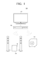
- FIG. 1 is a view illustrating an audio system 100 for wirelessly transmitting and receiving an audio signal according to an exemplary embodiment.
- the audio system 100 provides a user with a 5.1-channel audio signal.
- a 5.1-channel sound system may include a system body which supports a digital theater system (DTS) and a Dolby system, and 5.1-channel speakers which include a left-front speaker, a center speaker, a right-front speaker, a left-rear speaker, a right-rear speaker, and a subwoofer. It is understood that other exemplary embodiments are not limited to the audio system 100 providing a user with a 5.1 channel audio signal.
- DTS digital theater system
- Dolby system 5.1-channel speakers which include a left-front speaker, a center speaker, a right-front speaker, a left-rear speaker, a right-rear speaker, and a subwoofer.
- DTS digital theater system
- 5.1-channel speakers which include a left-front speaker, a center speaker,
- the audio system 100 provides a user with a 1 channel audio signal (i.e., mono signal), a 2 channel audio signal, a 7.1 channel audio signal, a 7.2 channel audio signal, a split audio signal (e.g., 5.1 channel for a first domain and 2 channel for a second domain), etc.
- a 1 channel audio signal i.e., mono signal
- a 2 channel audio signal i.e., a 2 channel audio signal
- a 7.1 channel audio signal a 7.2 channel audio signal
- a split audio signal e.g., 5.1 channel for a first domain and 2 channel for a second domain
- the audio system 100 includes a TV 110, a sound bar 120 which is an audio apparatus, a rear speaker unit 130, and a subwoofer speaker unit 140.
- the sound bar 120 is an audio apparatus which is separated from a display apparatus, and operates to process an audio signal of the display apparatus and to output audio.
- the center speaker and the front speakers are mounted in the sound bar 120.
- the TV 110 receives a broadcast signal from a broadcast station or a satellite over wire or wirelessly, or receives a video signal from a device connected thereto.
- the TV 110 processes the received broadcast signal or video signal, and extracts an audio signal from the received signal.
- the TV 110 wirelessly transmits the extracted audio signal to the sound bar 120.
- the transmitted audio signal may be a stereo channel audio signal.
- the sound bar 120 operates as a master speaker which processes an audio signal transmitted from the TV 110, and then outputs and distributes the transmitted audio signal. That is, the sound bar 120 processes the audio signal transmitted from the TV 110 to be a multi channel audio signal, transmits some of the processed audio signal to a slave speaker device (for example, rear speakers and a subwoofer speaker), and outputs the other audio signals.
- a slave speaker device for example, rear speakers and a subwoofer speaker
- the sound bar 120 converts the stereo channel audio signal into a 5.1-channel audio signal, and then processes the converted 5.1-channel audio signal.
- the sound bar 120 separates the converted 5.1-channel audio signal into audio signals for each channel.
- the sound bar 120 wirelessly transmits rear channel audio signals of the separated audio signals to the rear speaker unit 130.
- the rear speaker unit 130 separates the wirelessly received rear channel audio signals into a right-rear channel audio signal and a left-rear channel audio signal.
- the rear speaker unit 130 may separately receive the right-rear channel audio signal and a left-rear channel audio signal according to another exemplary embodiment.
- the rear speaker unit 130 amplifies the separated right-rear channel audio signal and left-rear channel audio signal, and transmits the amplified signals to the left-rear speaker and the right-rear speaker, respectively. Therefore, the right-rear channel audio signal is output to the right-rear speaker, and the left-rear channel audio signal is output to the left-rear speaker.
- the sound bar 120 wirelessly transmits the subwoofer channel audio signal of the separated audio signals to the subwoofer speaker unit 140.
- the subwoofer speaker unit 140 outputs the wirelessly received subwoofer channel audio signal.
- the sound bar 120 outputs the right-front channel audio signal, the left-front channel audio signal, and the center channel audio signal itself among the separated audio signals. That is, the right-front channel audio signal is output to the right-front speaker which is mounted in the sound bar 120, the left-front channel audio signal is output to the left-front speaker which is mounted in the sound bar 120, and the center channel audio signal is also output to the center speaker which is mounted in the sound bar 120.
- the sound bar 120 wirelessly receives an audio signal from the TV 110, and wirelessly transmits the audio signals to the rear speaker unit 130, and the subwoofer speaker unit 140 through a single radio transceiver unit. In this situation, as the sound bar 120 wirelessly communicates with a plurality of external devices, radio frequency interference may occur, thereby preventing a user from listening to audio of desired quality.
- the sound bar 120 transmits a plurality of audio signals using time division multiplexing so that radio frequency interference is minimized.
- the time division multiplexing will be explained with reference to FIG. 6 .
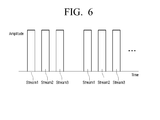
- FIG. 6 is a graph provided to explain an audio signal transmission method using time division multiplexing according to an exemplary embodiment.
- the time domain is divided into several timeslots, and the time slots are sequentially distributed to a plurality of radio channels.
- the TV 110 and the sound bar 120 use a radio channel which is referred to as Stream 1
- the sound bar 120 and the rear speaker unit 130 use a radio channel which is referred to as Stream 2
- the sound bar 120 and the subwoofer speaker unit 140 use a radio channel which is referred to as Stream 3.
- the data transmission time is divided into predetermined time slots as shown in FIG. 6 .
- Stream 1 is transmitted first, Stream 2 is transmitted subsequent to Stream 1, and then Stream 3 is transmitted and the process repeats itself (i.e., Stream 1 is transmitted again, and so on). That is, Stream 1, Stream 2, and Stream 3 are repeatedly transmitted in that order by predetermined time slots. Therefore, even if the sound bar 120 transmits and receives data through a plurality of radio channels, the radio channels are not overlapped. Accordingly, the sound bar 120 may eliminate the radio frequency interference.
- the sound bar 120 wirelessly transceives an audio signal to and from the TV 110, the rear speaker unit 130, and the subwoofer speaker unit 140. Therefore, a user may convert a stereo channel audio output of the TV 110 into a 5.1-channel audio output, and listen to the audio using the sound bar 120 without using an additional wired cable.
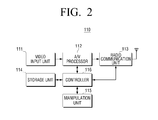
- FIG. 2 is a block diagram illustrating the TV 110 of the audio system 100 according to an exemplary embodiment.
- the TV 110 includes a video input unit 111, an audio/video (A/V) processor 112, a radio communication unit 113, a storage unit 114, a manipulation unit 115, and a controller 116.
- A/V audio/video
- the video input unit 111 is connected to an external device (for example, a DVD player), and receives a video signal.
- an external device for example, a DVD player
- the A/V processor 112 separates data input through the video input unit 111 into audio data and video data.
- a video processor performs signal processing such as video decoding and video scaling on the video data.
- An audio processor processes the audio data to be transmitted to the sound bar 120, and transmits the processed audio data to the radio communication unit 113.
- the audio signal may be an audio signal of a stereo channel type.
- the radio communication unit 113 selects a modulation scheme according to a control signal of the controller 116, and transmits the signal-processed audio signal to the sound bar 120.
- the radio communication unit 113 may be mounted in the TV 110, or may be a dongle (e.g., a universal serial bus dongle) for radio communication with the sound bar.
- the storage unit 114 stores a video received from the video input unit 111.
- the storage unit 114 may be implemented as a volatile memory (such as RAM, etc.) or a non-volatile memory (such as a hard disc drive, flash memory, ROM, etc.).
- the manipulation unit 115 receives an input from a user, and transmits the input to the controller 116.
- the manipulation unit 115 may be implemented using at least one of a remote controller, a pointing device, a touch pad, a touch screen, etc.
- the controller 116 controls overall operations of the TV 110. To be more specific, the controller 116 recognizes a user's command based on the input transmitted from the manipulation unit 115, and controls overall operations of the TV 110 according to the user's command. The controller 116 controls the A/V processor 112 to separately process the video data and audio data input through the video input unit 111. To transmit the processed audio signal to the sound bar 120, the controller 116 generates a control signal to select a modulation scheme, and transmits the generated control signal to the radio communication unit 113.
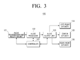
- FIG. 3 is a block diagram illustrating the sound bar 120 of the audio system 100 according to an exemplary embodiment.
- the sound bar 120 includes a radio transmission and reception unit 121, an audio processor 122, an audio output unit 123, a left-front speaker 124, a center speaker 125, a right-front speaker 126, and a controller 127.
- the radio transmission and reception unit 121 wirelessly receives a stereo channel audio signal from the TV 110.
- the radio transmission and reception unit 121 transmits the received stereo channel audio signal to the audio processor 122.
- the radio transmission and reception unit 121 wirelessly transmits to the rear speaker unit 130 a rear channel audio signal which is processed by the audio processor 122 to be separated. Furthermore, the radio transmission and reception unit 121 wirelessly transmits an audio signal of a subwoofer channel to the subwoofer speaker unit 140. Alternatively, the radio transmission and reception unit 121 may be implemented to transmit a right-rear channel audio signal and a left-rear channel audio signal to the rear speaker unit 130, and to transmit a subwoofer channel audio signal to the subwoofer speaker unit 140.
- the radio transmission and reception unit 121 wirelessly transmits and receives an audio signal using time division multiplexing.
- the audio processor 122 decodes a stereo channel audio signal which is received through the radio transmission and reception unit 121.
- the audio processor 122 converts the decoded stereo channel audio signal into, for example, a 5.1-channel audio signal, and then processes the converted signal.
- the audio processor 122 separates the decoded 5.1-channel audio signal into an audio signal which will be output to the speaker mounted in the sound bar 120 and an audio signal which will be wirelessly transmitted. Among the separated audio signals, the audio processor 122 transmits a 3-channel audio signal to be output through the speaker mounted in the sound bar 120 to the audio output unit 123.
- the 3-channel audio signal uses a right-front channel, a left-front channel, and a center channel.
- the audio processor 122 transmits a 2.1-channel audio signal to be wirelessly transmitted to the external speaker to the radio transmission and reception unit 121.
- the 2.1-channel audio signal uses a right-rear channel, a left-rear channel, and a subwoofer channel.
- the audio output unit 123 receives the 3-channel audio signal from the audio processor 122.
- the audio output unit 123 converts the received audio signal into a format in which an audio signal is capable of being output through a speaker.
- the audio output unit 123 converts the 3-channel audio signal separated by the audio processor 122 into a pulse width modulation (PWM) signal using a pulse width modulation integrated circuit (PWM IC) mounted therein, and switches the converted PWM signal to extract a left-front channel audio signal, a center channel audio signal, and a right-front channel audio signal.
- PWM pulse width modulation
- PWM IC pulse width modulation integrated circuit
- the audio output unit 123 transfers the extracted audio signal to each of the speakers mounted in the sound bar 120.
- the audio output unit 123 transfers the left-front channel audio signal to the left-front speaker 124, the center channel audio signal to the center speaker 125, and the right-front channel audio signal to the right-front speaker 126.
- the radio transmission and reception unit 121 wirelessly transmits the received 2.1-channel audio signal to the rear speaker unit 130 and the subwoofer speaker unit 140.
- the controller 127 controls overall operations of the sound bar 120. Specifically, the controller 127 controls the radio transmission and reception unit 121, the audio processor 122, and the audio output unit 123 to provide a user with a 5.1-channel audio signal. Furthermore, the controller 127 controls the audio processor 122 to convert the stereo channel audio signal transmitted to the radio transmission and reception unit 121 into a 5.1-channel audio signal. Also, the controller 127 controls the audio processor 122 to extract an audio signal of a subwoofer channel and an audio signal of a 2.1-channel of a rear channel from the 5.1-channel audio signal.
- the controller 127 controls the audio output unit 123 to transmit the subwoofer channel audio signal and the rear channel audio signal separated by the audio processor 122 to the radio transmission and reception unit 121. Moreover, the controller 127 controls the audio output unit 123 to transmit the left-front channel audio signal, the center channel audio signal, and the right-front channel audio signal to the left-front speaker 124, the center speaker 125, and the right-front speaker 126, respectively.
- FIG. 4 is a block diagram illustrating the rear speaker unit 130 of the audio system 100 according to an exemplary embodiment.
- the rear speaker unit 130 includes a radio reception unit 131, a 2-channel audio output unit 132, a left-rear speaker 133, a right-rear speaker 134, and a rear speaker controller 135.
- the radio reception unit 131 wirelessly receives an audio signal from the radio transmission and reception unit 121 of the sound bar 120.
- the audio signal wirelessly transmitted from the radio transmission and reception unit 121 is a rear channel audio signal.
- the audio signal wirelessly transmitted from the radio transmission and reception unit 121 may include only a rear channel audio signal, or may also include both a subwoofer channel audio signal and a rear channel audio signal. In the instant exemplary embodiment, the audio signal includes only a rear channel audio signal for convenience of description.
- the radio reception unit 131 transfers a wirelessly received audio signal to the 2-channel audio output unit 132.
- the 2-channel audio output unit 132 receives the audio signal from the radio reception unit 131, separates the received audio signal into a left-rear channel audio signal and a right-rear channel audio signal, and processes the separated audio signals.
- the 2-channel audio output unit 132 amplifies the separated left-rear channel audio signal and right-rear channel audio signal, and transfers the amplified audio signals to the left-rear speaker 133 and the right-rear speaker 134, respectively.
- the left-rear speaker 133 outputs a left-rear channel audio signal.
- the right-rear speaker 134 outputs a right-rear channel audio signal.
- the rear speaker controller 135 controls overall operations of the rear speaker unit 130. Specifically, the rear speaker controller 135 controls the 2-channel audio output unit 132 to amplify the received audio signal. Furthermore, the rear speaker controller 135 controls the 2-channel audio output unit 132 to separate the rear channel audio signals into a left-rear channel audio signal and a right-rear channel audio signal.
- FIG. 5 is a block diagram illustrating the subwoofer speaker unit 140 of the audio system 100 according to an exemplary embodiment.
- the subwoofer speaker unit 140 is provided to play back audio, in which a separate channel is used for low sound.
- the subwoofer speaker unit 140 includes a radio reception unit 141, a 0.1 channel audio output unit 142, a subwoofer speaker 143, and a subwoofer controller 144.
- the radio reception unit 141 wirelessly receives an audio signal from the radio transmission and reception unit 121 of the sound bar 120.
- the audio signal wirelessly transmitted by the radio transmission and reception unit 121 of the sound bar 120 may be an audio signal of a subwoofer channel.
- the radio reception unit 141 transfers the wirelessly received audio signal to the 0.1 channel audio output unit 142.
- the 0.1 channel audio output unit 142 amplifies the received subwoofer channel audio signal, and transmits the amplified audio signal to the subwoofer speaker 143. Then, the subwoofer speaker 143 outputs the subwoofer audio signal of 0.1 channel where low sound has been collected separately.
- the subwoofer controller 144 controls overall operations of the subwoofer speaker unit 140. To be more specific, the subwoofer controller 144 controls the radio reception unit 141 to have an identification (ID) matching with an ID of the radio transmission and reception unit 121 of the sound bar 120. Furthermore, the subwoofer controller 144 controls the 0.1-channel audio output unit 142 to amplify and output the received audio signal.
- ID identification
- the subwoofer controller 144 controls the 0.1-channel audio output unit 142 to amplify and output the received audio signal.
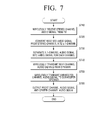
- FIG. 7 is a flowchart provided to explain a method of a sound bar 120 wirelessly transmitting and receiving an audio signal according to an exemplary embodiment.
- the sound bar 120 wirelessly receives a stereo channel audio signal from the TV 110 (S710).
- the sound bar 120 wirelessly receives an audio signal from the TV 110, the sound bar 120 processes the received audio signal to be converted into an audio signal of a 5.1-channel (S720).
- the sound bar 120 separates the converted 5.1-channel audio signal into an audio signal for each channel (S730). This is for the sound bar 120 to output a part of the converted 5.1-channel audio signal itself, and to wirelessly transmit the other part to an external wireless speaker. Therefore, the sound bar 120 separates the 5.1-channel audio signal into the right-front channel audio signal, the left-front channel audio signal, and the center channel audio signal to be output by the sound bar 120, and the subwoofer channel audio signal and the rear channel audio signals to be wirelessly transmitted to an external speaker.
- the sound bar 120 wirelessly transmits the rear channel audio signals from among the separated audio signals to the rear speaker unit 130 (S740).
- the rear channel audio signals transmitted to the rear speaker unit 130 are separated into the right-rear channel audio signal and the left-rear channel audio signal, and then amplified.
- the amplified audio signals are output to the left-rear speaker and the right-rear speaker, respectively.
- the sound bar 120 wirelessly transmits the subwoofer channel audio signal among the separated audio signals to the subwoofer speaker unit 140 (S750).
- the subwoofer channel audio signal wirelessly transmitted to the subwoofer speaker unit 140 is output to the subwoofer speaker 143.
- the sound bar 120 outputs the right-front channel audio signal, the left-front channel audio signal, and the center channel audio signal itself (S760). That is, the right-front channel audio signal is output to the right-front speaker mounted in the sound bar 120, the left-front channel audio signal is output to the left-front channel speaker mounted in the sound bar 120, and the center channel audio signal is output to the center speaker mounted in the sound bar 120.
- a user may listen to 5.1-channel audio through the sound bar 120 without using an additional cable instead of the stereo channel audio of the TV 110.
- the TV 110 is provided as the external device in the above-described exemplary embodiments, it is understood that the TV 110 is merely exemplary for convenience of description. That is, it is understood that aspects of the exemplary embodiments may be applied to any device which wirelessly provides an audio signal.
- the first external device may be embodied using a wall-mounted display device, a computer, and an MPEG layer 3 (MP3) player.
- MP3 MPEG layer 3
- the sound bar 120 is provided as an audio device in the above-described exemplary embodiments, it is understood that the sound bar 120 is merely exemplary for convenience of description. That is, aspects of the exemplary embodiments may be applied to any device which wirelessly provides a multi channel audio signal.
- the audio device may be a home theater or a wall-mounted sound bar.
- audio device is used to provide a 5.1-channel audio signal
- this is merely exemplary. That is, aspects of the exemplary embodiments may be applied to any audio device which provides a multi-channel audio signal, such as a 6.1 channel or a 7.1 channel audio system.
- an audio signal of a 2.1 channel having a subwoofer channel and rear channels is wirelessly transmitted, it is understood that this is merely exemplary for convenience of description. That is, another exemplary embodiment may be implemented to wirelessly transmit an audio signal of at least one of rear channels, front channels, and a subwoofer channel.
- an audio device wirelessly communicates with a plurality of external devices, and thus a user may connect the audio device to the plurality of external devices without using cables.
- the exemplary embodiments can also be embodied as computer-readable code on a computer-readable recording medium.
- the computer-readable recording medium is any data storage device that can store data that can be thereafter read by a computer system. Examples of the computer-readable recording medium include read-only memory (ROM), random-access memory (RAM), CD-ROMs, magnetic tapes, floppy disks, and optical data storage devices.
- the computer-readable recording medium can also be distributed over network-coupled computer systems so that the computer-readable code is stored and executed in a distributed fashion.
- the exemplary embodiments may be written as computer programs transmitted over a computer-readable transmission medium, such as a carrier wave, and received and implemented in general-use digital computers that execute the programs.
- one or more units of the audio system 100 can include a processor or microprocessor executing a computer program stored in a computer-readable medium.
Landscapes
- Engineering & Computer Science (AREA)
- Signal Processing (AREA)
- Physics & Mathematics (AREA)
- Acoustics & Sound (AREA)
- Health & Medical Sciences (AREA)
- General Health & Medical Sciences (AREA)
- Otolaryngology (AREA)
- Computer Networks & Wireless Communication (AREA)
- Multimedia (AREA)
- Stereophonic System (AREA)
- Circuit For Audible Band Transducer (AREA)
- Details Of Audible-Bandwidth Transducers (AREA)
Applications Claiming Priority (2)
| Application Number | Priority Date | Filing Date | Title |
|---|---|---|---|
| KR1020090129674A KR20110072650A (ko) | 2009-12-23 | 2009-12-23 | 오디오 장치 및 이의 오디오 신호 전송 방법, 그리고 오디오 시스템 |
| EP10195275A EP2357853A1 (de) | 2009-12-23 | 2010-12-15 | Audiovorrichtung, Audiosignalübertragungsverfahren und Audiosystem |
Related Parent Applications (2)
| Application Number | Title | Priority Date | Filing Date |
|---|---|---|---|
| EP10195275A Division EP2357853A1 (de) | 2009-12-23 | 2010-12-15 | Audiovorrichtung, Audiosignalübertragungsverfahren und Audiosystem |
| EP10195275.2 Division | 2010-12-15 |
Publications (3)
| Publication Number | Publication Date |
|---|---|
| EP2498515A2 true EP2498515A2 (de) | 2012-09-12 |
| EP2498515A3 EP2498515A3 (de) | 2012-10-31 |
| EP2498515B1 EP2498515B1 (de) | 2015-11-04 |
Family
ID=43901273
Family Applications (2)
| Application Number | Title | Priority Date | Filing Date |
|---|---|---|---|
| EP12171407.5A Not-in-force EP2498515B1 (de) | 2009-12-23 | 2010-12-15 | Audiogerät, Audiosignalübertragungsmethode, sowie Audiosystem |
| EP10195275A Ceased EP2357853A1 (de) | 2009-12-23 | 2010-12-15 | Audiovorrichtung, Audiosignalübertragungsverfahren und Audiosystem |
Family Applications After (1)
| Application Number | Title | Priority Date | Filing Date |
|---|---|---|---|
| EP10195275A Ceased EP2357853A1 (de) | 2009-12-23 | 2010-12-15 | Audiovorrichtung, Audiosignalübertragungsverfahren und Audiosystem |
Country Status (3)
| Country | Link |
|---|---|
| US (2) | US8457334B2 (de) |
| EP (2) | EP2498515B1 (de) |
| KR (1) | KR20110072650A (de) |
Cited By (1)
| Publication number | Priority date | Publication date | Assignee | Title |
|---|---|---|---|---|
| US20240187803A1 (en) * | 2011-10-14 | 2024-06-06 | Sonos, Inc. | Network Device for Media Playback |
Families Citing this family (79)
| Publication number | Priority date | Publication date | Assignee | Title |
|---|---|---|---|---|
| US11106425B2 (en) | 2003-07-28 | 2021-08-31 | Sonos, Inc. | Synchronizing operations among a plurality of independently clocked digital data processing devices |
| US8020023B2 (en) | 2003-07-28 | 2011-09-13 | Sonos, Inc. | Systems and methods for synchronizing operations among a plurality of independently clocked digital data processing devices without a voltage controlled crystal oscillator |
| US11294618B2 (en) | 2003-07-28 | 2022-04-05 | Sonos, Inc. | Media player system |
| US10613817B2 (en) | 2003-07-28 | 2020-04-07 | Sonos, Inc. | Method and apparatus for displaying a list of tracks scheduled for playback by a synchrony group |
| US8086752B2 (en) | 2006-11-22 | 2011-12-27 | Sonos, Inc. | Systems and methods for synchronizing operations among a plurality of independently clocked digital data processing devices that independently source digital data |
| US11106424B2 (en) | 2003-07-28 | 2021-08-31 | Sonos, Inc. | Synchronizing operations among a plurality of independently clocked digital data processing devices |
| US11650784B2 (en) | 2003-07-28 | 2023-05-16 | Sonos, Inc. | Adjusting volume levels |
| US8234395B2 (en) | 2003-07-28 | 2012-07-31 | Sonos, Inc. | System and method for synchronizing operations among a plurality of independently clocked digital data processing devices |
| US8290603B1 (en) | 2004-06-05 | 2012-10-16 | Sonos, Inc. | User interfaces for controlling and manipulating groupings in a multi-zone media system |
| US9977561B2 (en) | 2004-04-01 | 2018-05-22 | Sonos, Inc. | Systems, methods, apparatus, and articles of manufacture to provide guest access |
| US9374607B2 (en) | 2012-06-26 | 2016-06-21 | Sonos, Inc. | Media playback system with guest access |
| US8868698B2 (en) | 2004-06-05 | 2014-10-21 | Sonos, Inc. | Establishing a secure wireless network with minimum human intervention |
| US8326951B1 (en) | 2004-06-05 | 2012-12-04 | Sonos, Inc. | Establishing a secure wireless network with minimum human intervention |
| US12167216B2 (en) | 2006-09-12 | 2024-12-10 | Sonos, Inc. | Playback device pairing |
| US8483853B1 (en) | 2006-09-12 | 2013-07-09 | Sonos, Inc. | Controlling and manipulating groupings in a multi-zone media system |
| US8788080B1 (en) | 2006-09-12 | 2014-07-22 | Sonos, Inc. | Multi-channel pairing in a media system |
| US9202509B2 (en) | 2006-09-12 | 2015-12-01 | Sonos, Inc. | Controlling and grouping in a multi-zone media system |
| KR20090102089A (ko) * | 2008-03-25 | 2009-09-30 | 삼성전자주식회사 | 오디오 신호를 무선으로 전송하는 오디오 기기 및 전송방법 |
| KR20110072650A (ko) * | 2009-12-23 | 2011-06-29 | 삼성전자주식회사 | 오디오 장치 및 이의 오디오 신호 전송 방법, 그리고 오디오 시스템 |
| US9237324B2 (en) | 2010-10-22 | 2016-01-12 | Phorus, Inc. | Playback synchronization |
| US11265652B2 (en) | 2011-01-25 | 2022-03-01 | Sonos, Inc. | Playback device pairing |
| US11429343B2 (en) | 2011-01-25 | 2022-08-30 | Sonos, Inc. | Stereo playback configuration and control |
| US9094706B2 (en) | 2011-10-21 | 2015-07-28 | Sonos, Inc. | Systems and methods for wireless music playback |
| US9084058B2 (en) | 2011-12-29 | 2015-07-14 | Sonos, Inc. | Sound field calibration using listener localization |
| US9344292B2 (en) * | 2011-12-30 | 2016-05-17 | Sonos, Inc. | Systems and methods for player setup room names |
| WO2013150334A1 (en) * | 2012-04-03 | 2013-10-10 | Nokia Corporation | Apparatus for splitting and outputting multi-channel composite audio signals |
| US9729115B2 (en) | 2012-04-27 | 2017-08-08 | Sonos, Inc. | Intelligently increasing the sound level of player |
| KR20130137903A (ko) | 2012-06-08 | 2013-12-18 | 삼성전자주식회사 | 음향 출력 장치, 오디오 처리 장치, 음향 출력 방법 및 오디오 처리 방법 |
| US9031255B2 (en) | 2012-06-15 | 2015-05-12 | Sonos, Inc. | Systems, methods, apparatus, and articles of manufacture to provide low-latency audio |
| US9706323B2 (en) | 2014-09-09 | 2017-07-11 | Sonos, Inc. | Playback device calibration |
| US9219460B2 (en) | 2014-03-17 | 2015-12-22 | Sonos, Inc. | Audio settings based on environment |
| US9106192B2 (en) | 2012-06-28 | 2015-08-11 | Sonos, Inc. | System and method for device playback calibration |
| US9112991B2 (en) | 2012-08-27 | 2015-08-18 | Nokia Technologies Oy | Playing synchronized multichannel media on a combination of devices |
| JP6085029B2 (ja) | 2012-08-31 | 2017-02-22 | ドルビー ラボラトリーズ ライセンシング コーポレイション | 種々の聴取環境におけるオブジェクトに基づくオーディオのレンダリング及び再生のためのシステム |
| US9008330B2 (en) | 2012-09-28 | 2015-04-14 | Sonos, Inc. | Crossover frequency adjustments for audio speakers |
| US9516440B2 (en) | 2012-10-01 | 2016-12-06 | Sonos | Providing a multi-channel and a multi-zone audio environment |
| US9131298B2 (en) | 2012-11-28 | 2015-09-08 | Qualcomm Incorporated | Constrained dynamic amplitude panning in collaborative sound systems |
| AU2013276983B2 (en) * | 2012-12-26 | 2017-05-18 | Samsung Electronics Co., Ltd. | Terminal device and method for controlling thereof |
| CN103067848B (zh) * | 2012-12-28 | 2015-08-05 | 小米科技有限责任公司 | 实现多声道播放声音的方法、设备及系统 |
| TWI477160B (zh) * | 2013-01-22 | 2015-03-11 | Aevoe Inc | 組合式無線音響 |
| KR102090490B1 (ko) * | 2013-08-30 | 2020-03-18 | 삼성전자 주식회사 | 오디오 채널 설정 방법 및 시스템 |
| US9554211B2 (en) * | 2014-01-03 | 2017-01-24 | Summit Semiconductor Llc | Wireless speaker unit |
| US9226087B2 (en) | 2014-02-06 | 2015-12-29 | Sonos, Inc. | Audio output balancing during synchronized playback |
| US9226073B2 (en) | 2014-02-06 | 2015-12-29 | Sonos, Inc. | Audio output balancing during synchronized playback |
| KR20150102337A (ko) | 2014-02-28 | 2015-09-07 | 삼성전자주식회사 | 오디오 출력 장치, 그 제어 방법 및 오디오 출력 시스템 |
| US9264839B2 (en) | 2014-03-17 | 2016-02-16 | Sonos, Inc. | Playback device configuration based on proximity detection |
| US9952825B2 (en) | 2014-09-09 | 2018-04-24 | Sonos, Inc. | Audio processing algorithms |
| US9665341B2 (en) | 2015-02-09 | 2017-05-30 | Sonos, Inc. | Synchronized audio mixing |
| US10248376B2 (en) | 2015-06-11 | 2019-04-02 | Sonos, Inc. | Multiple groupings in a playback system |
| CN104967927A (zh) * | 2015-07-01 | 2015-10-07 | 南京熊猫电子股份有限公司 | 一种双声道条形音响 |
| JP6437695B2 (ja) | 2015-09-17 | 2018-12-12 | ソノズ インコーポレイテッド | オーディオ再生デバイスのキャリブレーションを容易にする方法 |
| US9693165B2 (en) | 2015-09-17 | 2017-06-27 | Sonos, Inc. | Validation of audio calibration using multi-dimensional motion check |
| US9888305B2 (en) * | 2015-11-13 | 2018-02-06 | Harman Becker Automotive Systems Gmbh | Portable speaker system for providing audio channels based on location |
| US10303422B1 (en) | 2016-01-05 | 2019-05-28 | Sonos, Inc. | Multiple-device setup |
| US9743207B1 (en) | 2016-01-18 | 2017-08-22 | Sonos, Inc. | Calibration using multiple recording devices |
| US11106423B2 (en) | 2016-01-25 | 2021-08-31 | Sonos, Inc. | Evaluating calibration of a playback device |
| US10003899B2 (en) | 2016-01-25 | 2018-06-19 | Sonos, Inc. | Calibration with particular locations |
| KR102490548B1 (ko) | 2016-01-25 | 2023-01-19 | 삼성전자주식회사 | 사용자 단말 장치 및 그 제어 방법 |
| US9860662B2 (en) | 2016-04-01 | 2018-01-02 | Sonos, Inc. | Updating playback device configuration information based on calibration data |
| US9864574B2 (en) | 2016-04-01 | 2018-01-09 | Sonos, Inc. | Playback device calibration based on representation spectral characteristics |
| US9763018B1 (en) | 2016-04-12 | 2017-09-12 | Sonos, Inc. | Calibration of audio playback devices |
| US9794710B1 (en) | 2016-07-15 | 2017-10-17 | Sonos, Inc. | Spatial audio correction |
| US10219091B2 (en) | 2016-07-18 | 2019-02-26 | Bose Corporation | Dynamically changing master audio playback device |
| US10372406B2 (en) | 2016-07-22 | 2019-08-06 | Sonos, Inc. | Calibration interface |
| US10459684B2 (en) | 2016-08-05 | 2019-10-29 | Sonos, Inc. | Calibration of a playback device based on an estimated frequency response |
| US10712997B2 (en) | 2016-10-17 | 2020-07-14 | Sonos, Inc. | Room association based on name |
| KR102555485B1 (ko) | 2016-11-07 | 2023-07-14 | 삼성전자주식회사 | 스피커 장치, 스피커 장치와 연결되는 전자 장치 및 스피커 장치의 제어 방법 |
| US9820073B1 (en) | 2017-05-10 | 2017-11-14 | Tls Corp. | Extracting a common signal from multiple audio signals |
| US10299061B1 (en) | 2018-08-28 | 2019-05-21 | Sonos, Inc. | Playback device calibration |
| US11206484B2 (en) | 2018-08-28 | 2021-12-21 | Sonos, Inc. | Passive speaker authentication |
| WO2020220181A1 (en) * | 2019-04-29 | 2020-11-05 | Harman International Industries, Incorporated | A speaker with broadcasting mode and broadcasting method thereof |
| US11178504B2 (en) * | 2019-05-17 | 2021-11-16 | Sonos, Inc. | Wireless multi-channel headphone systems and methods |
| US10734965B1 (en) | 2019-08-12 | 2020-08-04 | Sonos, Inc. | Audio calibration of a portable playback device |
| KR102711321B1 (ko) | 2020-01-02 | 2024-09-30 | 삼성전자주식회사 | 디스플레이 장치 및 그 제어 방법 |
| US12549945B2 (en) | 2020-09-25 | 2026-02-10 | Sonos, Inc. | Intelligent setup for playback devices |
| US12322390B2 (en) | 2021-09-30 | 2025-06-03 | Sonos, Inc. | Conflict management for wake-word detection processes |
| US11895472B2 (en) * | 2022-06-08 | 2024-02-06 | Bose Corporation | Audio system with mixed rendering audio enhancement |
| CN116614150B (zh) * | 2023-03-15 | 2025-11-25 | 北京允芯微电子有限公司 | 音频收发同步方法、音频接收芯片和无线传声系统 |
| KR20250063547A (ko) * | 2023-11-01 | 2025-05-08 | 삼성전자주식회사 | 오디오 출력 장치 및 그 방법 |
Family Cites Families (38)
| Publication number | Priority date | Publication date | Assignee | Title |
|---|---|---|---|---|
| DE3174369D1 (en) * | 1981-12-24 | 1986-05-15 | Itt Ind Gmbh Deutsche | Circuit for the processing, transmission and acoustic reproduction of digitalized tone frequency signals |
| US5491839A (en) * | 1991-08-21 | 1996-02-13 | L. S. Research, Inc. | System for short range transmission of a plurality of signals simultaneously over the air using high frequency carriers |
| US5666422A (en) * | 1994-05-18 | 1997-09-09 | Harrison; Robert W. | Remote speaker for surround-sound applications |
| EP0880827A1 (de) * | 1996-02-07 | 1998-12-02 | L.S. Research, Inc. | Digitales schnurloses lautsprechersystem |
| KR100268473B1 (ko) * | 1997-12-30 | 2000-10-16 | 윤종용 | 무선 스피커를 갖는 오디오 출력장치 |
| US6590982B1 (en) * | 1998-08-21 | 2003-07-08 | Jinsaun Chen | Wireless stereo center speaker system |
| US6466832B1 (en) * | 1998-08-24 | 2002-10-15 | Altec Lansing R & D Center Israel | High quality wireless audio speakers |
| US6487296B1 (en) * | 1998-09-30 | 2002-11-26 | Steven W. Allen | Wireless surround sound speaker system |
| JP2001127712A (ja) * | 1999-10-29 | 2001-05-11 | Yazaki Corp | 音響システム |
| US6684060B1 (en) * | 2000-04-11 | 2004-01-27 | Agere Systems Inc. | Digital wireless premises audio system and method of operation thereof |
| US6778869B2 (en) * | 2000-12-11 | 2004-08-17 | Sony Corporation | System and method for request, delivery and use of multimedia files for audiovisual entertainment in the home environment |
| US6860609B2 (en) * | 2001-12-26 | 2005-03-01 | Infocus Corporation | Image-rendering device |
| US7853341B2 (en) | 2002-01-25 | 2010-12-14 | Ksc Industries, Inc. | Wired, wireless, infrared, and powerline audio entertainment systems |
| TW552819B (en) * | 2002-06-21 | 2003-09-11 | Via Tech Inc | Phonic system with wireless speaker |
| US20040037433A1 (en) * | 2002-08-21 | 2004-02-26 | Heng-Chien Chen | Multi-channel wireless professional audio system |
| US20040039462A1 (en) * | 2002-08-21 | 2004-02-26 | Heng-Chien Chen | Multi-channel wireless professional audio system using sound card |
| US20050136839A1 (en) * | 2003-05-28 | 2005-06-23 | Nambirajan Seshadri | Modular wireless multimedia device |
| US7024003B2 (en) * | 2003-06-26 | 2006-04-04 | Bellsouth Intellectual Property Corporation | Wireless speaker system suitable for hard-wired audio system |
| TWM247863U (en) * | 2003-08-01 | 2004-10-21 | Meiloon Ind Co Ltd | Improved structure of projector |
| US7653344B1 (en) * | 2004-01-09 | 2010-01-26 | Neosonik | Wireless digital audio/video playback system |
| US7483538B2 (en) * | 2004-03-02 | 2009-01-27 | Ksc Industries, Inc. | Wireless and wired speaker hub for a home theater system |
| US20060009985A1 (en) | 2004-06-16 | 2006-01-12 | Samsung Electronics Co., Ltd. | Multi-channel audio system |
| US7252383B2 (en) * | 2004-12-20 | 2007-08-07 | Meiloon Industrial Co., Ltd. | Wireless audio output assembly for projectors |
| US8050203B2 (en) * | 2004-12-22 | 2011-11-01 | Eleven Engineering Inc. | Multi-channel digital wireless audio system |
| WO2007031896A1 (en) * | 2005-09-13 | 2007-03-22 | Koninklijke Philips Electronics N.V. | Audio coding |
| US20070087686A1 (en) * | 2005-10-18 | 2007-04-19 | Nokia Corporation | Audio playback device and method of its operation |
| US7539889B2 (en) * | 2005-12-30 | 2009-05-26 | Avega Systems Pty Ltd | Media data synchronization in a wireless network |
| KR100750178B1 (ko) * | 2006-07-10 | 2007-08-17 | 삼성전자주식회사 | 홈 시어터 시스템의 무선 리어 스피커 확장 장치 및 방법 |
| WO2008046143A1 (en) * | 2006-10-17 | 2008-04-24 | Avega Systems Pty Ltd | Configuring and connecting to a media wireless network |
| WO2008046141A1 (en) * | 2006-10-17 | 2008-04-24 | Avega Systems Pty Ltd | Unification of multimedia devices |
| US8165315B2 (en) * | 2007-02-09 | 2012-04-24 | Sky Cross Inc. | Multichannel wireless system |
| US8320824B2 (en) * | 2007-09-24 | 2012-11-27 | Aliphcom, Inc. | Methods and systems to provide automatic configuration of wireless speakers |
| KR100962595B1 (ko) | 2008-03-18 | 2010-06-11 | 에스텍 주식회사 | 사운드 바 스피커 |
| KR20090102089A (ko) * | 2008-03-25 | 2009-09-30 | 삼성전자주식회사 | 오디오 신호를 무선으로 전송하는 오디오 기기 및 전송방법 |
| KR20090132917A (ko) * | 2008-06-23 | 2009-12-31 | 삼성전자주식회사 | 제어 디바이스 및 그 제어 방법 |
| KR20100066949A (ko) * | 2008-12-10 | 2010-06-18 | 삼성전자주식회사 | 오디오 기기 및 그의 신호보정방법 |
| KR101688963B1 (ko) * | 2009-12-18 | 2016-12-22 | 삼성전자주식회사 | 멀티밴드 무선 통신 장치 및 이의 채널 할당 방법 |
| KR20110072650A (ko) * | 2009-12-23 | 2011-06-29 | 삼성전자주식회사 | 오디오 장치 및 이의 오디오 신호 전송 방법, 그리고 오디오 시스템 |
-
2009
- 2009-12-23 KR KR1020090129674A patent/KR20110072650A/ko not_active Ceased
-
2010
- 2010-10-12 US US12/902,367 patent/US8457334B2/en active Active
- 2010-12-15 EP EP12171407.5A patent/EP2498515B1/de not_active Not-in-force
- 2010-12-15 EP EP10195275A patent/EP2357853A1/de not_active Ceased
-
2013
- 2013-05-15 US US13/895,105 patent/US8705780B2/en active Active
Non-Patent Citations (1)
| Title |
|---|
| None |
Cited By (1)
| Publication number | Priority date | Publication date | Assignee | Title |
|---|---|---|---|---|
| US20240187803A1 (en) * | 2011-10-14 | 2024-06-06 | Sonos, Inc. | Network Device for Media Playback |
Also Published As
| Publication number | Publication date |
|---|---|
| US20130251178A1 (en) | 2013-09-26 |
| EP2498515B1 (de) | 2015-11-04 |
| EP2357853A1 (de) | 2011-08-17 |
| KR20110072650A (ko) | 2011-06-29 |
| EP2498515A3 (de) | 2012-10-31 |
| US20110150228A1 (en) | 2011-06-23 |
| US8457334B2 (en) | 2013-06-04 |
| US8705780B2 (en) | 2014-04-22 |
Similar Documents
| Publication | Publication Date | Title |
|---|---|---|
| US8457334B2 (en) | Audio apparatus, audio signal transmission method, and audio system | |
| US7483538B2 (en) | Wireless and wired speaker hub for a home theater system | |
| KR100821501B1 (ko) | 근거리용 양방향 브로드캐스팅시스템 | |
| CN213339098U (zh) | 无线发射装置 | |
| US20130329893A1 (en) | Audio output apparatus and method for outputting audio | |
| US10237653B2 (en) | Speaker apparatus, electronic apparatus connected therewith, and controlling method thereof | |
| CN204669601U (zh) | 一种全无线高保真音响系统 | |
| CN111970613A (zh) | 无线发射装置、控制方法及显示装置 | |
| US11589180B2 (en) | Electronic apparatus, control method thereof, and recording medium | |
| KR100728019B1 (ko) | 무선 오디오 전송 방법 및 그 장치 | |
| EP1471772A2 (de) | Gerät und Verfahren zur Audiodatenverarbeitung, entsprechendes Programm und Aufzeichnungsmedium zum Speichern dieses Programmes | |
| US20120148055A1 (en) | Audio processing apparatus, audio receiver and method for providing audio thereof | |
| KR101634387B1 (ko) | 멀티 채널 오디오 재생 장치 및 시스템 | |
| JP2009283997A (ja) | 音声出力装置、プログラム、および記録媒体 | |
| JP2016178422A (ja) | 音声無線伝送システム、スピーカ機器、及びソース機器 | |
| JP2016174226A (ja) | 音声無線伝送システム、スピーカ機器、及びソース機器 | |
| JP2006050241A (ja) | 復号化装置 | |
| KR20150079514A (ko) | 오디오 장치 및 이의 오디오 신호 전송 방법, 그리고 오디오 시스템 | |
| KR100923872B1 (ko) | 홈시어터 시스템의 오디오 신호 출력장치 및 이를 이용한신호 출력방법 | |
| US8243947B2 (en) | Image apparatus and method for transmitting audio data | |
| JP2016178396A (ja) | 音声無線伝送システム、スピーカ機器、及びソース機器 | |
| JP2012156598A (ja) | 画像音声出力装置 | |
| KR20160002319U (ko) | 오디오 일체형 셋톱박스 | |
| JP2007134943A (ja) | オーディオシステム |
Legal Events
| Date | Code | Title | Description |
|---|---|---|---|
| PUAI | Public reference made under article 153(3) epc to a published international application that has entered the european phase |
Free format text: ORIGINAL CODE: 0009012 |
|
| AC | Divisional application: reference to earlier application |
Ref document number: 2357853 Country of ref document: EP Kind code of ref document: P |
|
| AK | Designated contracting states |
Kind code of ref document: A2 Designated state(s): AL AT BE BG CH CY CZ DE DK EE ES FI FR GB GR HR HU IE IS IT LI LT LU LV MC MK MT NL NO PL PT RO RS SE SI SK SM TR |
|
| AX | Request for extension of the european patent |
Extension state: BA ME |
|
| RAP1 | Party data changed (applicant data changed or rights of an application transferred) |
Owner name: SAMSUNG ELECTRONICS CO., LTD. |
|
| PUAL | Search report despatched |
Free format text: ORIGINAL CODE: 0009013 |
|
| AK | Designated contracting states |
Kind code of ref document: A3 Designated state(s): AL AT BE BG CH CY CZ DE DK EE ES FI FR GB GR HR HU IE IS IT LI LT LU LV MC MK MT NL NO PL PT RO RS SE SI SK SM TR |
|
| AX | Request for extension of the european patent |
Extension state: BA ME |
|
| RIC1 | Information provided on ipc code assigned before grant |
Ipc: H04R 3/12 20060101ALI20120924BHEP Ipc: H04S 3/00 20060101AFI20120924BHEP Ipc: H04R 5/02 20060101ALI20120924BHEP Ipc: H04S 5/00 20060101ALI20120924BHEP |
|
| 17P | Request for examination filed |
Effective date: 20130429 |
|
| 17Q | First examination report despatched |
Effective date: 20130606 |
|
| GRAP | Despatch of communication of intention to grant a patent |
Free format text: ORIGINAL CODE: EPIDOSNIGR1 |
|
| INTG | Intention to grant announced |
Effective date: 20150527 |
|
| GRAS | Grant fee paid |
Free format text: ORIGINAL CODE: EPIDOSNIGR3 |
|
| GRAA | (expected) grant |
Free format text: ORIGINAL CODE: 0009210 |
|
| AC | Divisional application: reference to earlier application |
Ref document number: 2357853 Country of ref document: EP Kind code of ref document: P |
|
| AK | Designated contracting states |
Kind code of ref document: B1 Designated state(s): AL AT BE BG CH CY CZ DE DK EE ES FI FR GB GR HR HU IE IS IT LI LT LU LV MC MK MT NL NO PL PT RO RS SE SI SK SM TR |
|
| REG | Reference to a national code |
Ref country code: GB Ref legal event code: FG4D |
|
| REG | Reference to a national code |
Ref country code: CH Ref legal event code: EP |
|
| REG | Reference to a national code |
Ref country code: AT Ref legal event code: REF Ref document number: 759905 Country of ref document: AT Kind code of ref document: T Effective date: 20151115 |
|
| REG | Reference to a national code |
Ref country code: IE Ref legal event code: FG4D |
|
| REG | Reference to a national code |
Ref country code: DE Ref legal event code: R096 Ref document number: 602010028887 Country of ref document: DE |
|
| REG | Reference to a national code |
Ref country code: FR Ref legal event code: PLFP Year of fee payment: 6 |
|
| REG | Reference to a national code |
Ref country code: NL Ref legal event code: FP |
|
| REG | Reference to a national code |
Ref country code: LT Ref legal event code: MG4D |
|
| REG | Reference to a national code |
Ref country code: AT Ref legal event code: MK05 Ref document number: 759905 Country of ref document: AT Kind code of ref document: T Effective date: 20151104 |
|
| PG25 | Lapsed in a contracting state [announced via postgrant information from national office to epo] |
Ref country code: NO Free format text: LAPSE BECAUSE OF FAILURE TO SUBMIT A TRANSLATION OF THE DESCRIPTION OR TO PAY THE FEE WITHIN THE PRESCRIBED TIME-LIMIT Effective date: 20160204 Ref country code: HR Free format text: LAPSE BECAUSE OF FAILURE TO SUBMIT A TRANSLATION OF THE DESCRIPTION OR TO PAY THE FEE WITHIN THE PRESCRIBED TIME-LIMIT Effective date: 20151104 Ref country code: LT Free format text: LAPSE BECAUSE OF FAILURE TO SUBMIT A TRANSLATION OF THE DESCRIPTION OR TO PAY THE FEE WITHIN THE PRESCRIBED TIME-LIMIT Effective date: 20151104 Ref country code: IS Free format text: LAPSE BECAUSE OF FAILURE TO SUBMIT A TRANSLATION OF THE DESCRIPTION OR TO PAY THE FEE WITHIN THE PRESCRIBED TIME-LIMIT Effective date: 20160304 Ref country code: ES Free format text: LAPSE BECAUSE OF FAILURE TO SUBMIT A TRANSLATION OF THE DESCRIPTION OR TO PAY THE FEE WITHIN THE PRESCRIBED TIME-LIMIT Effective date: 20151104 Ref country code: IT Free format text: LAPSE BECAUSE OF FAILURE TO SUBMIT A TRANSLATION OF THE DESCRIPTION OR TO PAY THE FEE WITHIN THE PRESCRIBED TIME-LIMIT Effective date: 20151104 |
|
| PG25 | Lapsed in a contracting state [announced via postgrant information from national office to epo] |
Ref country code: SE Free format text: LAPSE BECAUSE OF FAILURE TO SUBMIT A TRANSLATION OF THE DESCRIPTION OR TO PAY THE FEE WITHIN THE PRESCRIBED TIME-LIMIT Effective date: 20151104 Ref country code: LV Free format text: LAPSE BECAUSE OF FAILURE TO SUBMIT A TRANSLATION OF THE DESCRIPTION OR TO PAY THE FEE WITHIN THE PRESCRIBED TIME-LIMIT Effective date: 20151104 Ref country code: FI Free format text: LAPSE BECAUSE OF FAILURE TO SUBMIT A TRANSLATION OF THE DESCRIPTION OR TO PAY THE FEE WITHIN THE PRESCRIBED TIME-LIMIT Effective date: 20151104 Ref country code: GR Free format text: LAPSE BECAUSE OF FAILURE TO SUBMIT A TRANSLATION OF THE DESCRIPTION OR TO PAY THE FEE WITHIN THE PRESCRIBED TIME-LIMIT Effective date: 20160205 Ref country code: PL Free format text: LAPSE BECAUSE OF FAILURE TO SUBMIT A TRANSLATION OF THE DESCRIPTION OR TO PAY THE FEE WITHIN THE PRESCRIBED TIME-LIMIT Effective date: 20151104 Ref country code: RS Free format text: LAPSE BECAUSE OF FAILURE TO SUBMIT A TRANSLATION OF THE DESCRIPTION OR TO PAY THE FEE WITHIN THE PRESCRIBED TIME-LIMIT Effective date: 20151104 Ref country code: BE Free format text: LAPSE BECAUSE OF NON-PAYMENT OF DUE FEES Effective date: 20151231 Ref country code: AT Free format text: LAPSE BECAUSE OF FAILURE TO SUBMIT A TRANSLATION OF THE DESCRIPTION OR TO PAY THE FEE WITHIN THE PRESCRIBED TIME-LIMIT Effective date: 20151104 Ref country code: PT Free format text: LAPSE BECAUSE OF FAILURE TO SUBMIT A TRANSLATION OF THE DESCRIPTION OR TO PAY THE FEE WITHIN THE PRESCRIBED TIME-LIMIT Effective date: 20160304 |
|
| PG25 | Lapsed in a contracting state [announced via postgrant information from national office to epo] |
Ref country code: CZ Free format text: LAPSE BECAUSE OF FAILURE TO SUBMIT A TRANSLATION OF THE DESCRIPTION OR TO PAY THE FEE WITHIN THE PRESCRIBED TIME-LIMIT Effective date: 20151104 |
|
| REG | Reference to a national code |
Ref country code: CH Ref legal event code: PL |
|
| REG | Reference to a national code |
Ref country code: DE Ref legal event code: R097 Ref document number: 602010028887 Country of ref document: DE |
|
| PG25 | Lapsed in a contracting state [announced via postgrant information from national office to epo] |
Ref country code: SM Free format text: LAPSE BECAUSE OF FAILURE TO SUBMIT A TRANSLATION OF THE DESCRIPTION OR TO PAY THE FEE WITHIN THE PRESCRIBED TIME-LIMIT Effective date: 20151104 Ref country code: DK Free format text: LAPSE BECAUSE OF FAILURE TO SUBMIT A TRANSLATION OF THE DESCRIPTION OR TO PAY THE FEE WITHIN THE PRESCRIBED TIME-LIMIT Effective date: 20151104 Ref country code: RO Free format text: LAPSE BECAUSE OF FAILURE TO SUBMIT A TRANSLATION OF THE DESCRIPTION OR TO PAY THE FEE WITHIN THE PRESCRIBED TIME-LIMIT Effective date: 20151104 Ref country code: SK Free format text: LAPSE BECAUSE OF FAILURE TO SUBMIT A TRANSLATION OF THE DESCRIPTION OR TO PAY THE FEE WITHIN THE PRESCRIBED TIME-LIMIT Effective date: 20151104 Ref country code: EE Free format text: LAPSE BECAUSE OF FAILURE TO SUBMIT A TRANSLATION OF THE DESCRIPTION OR TO PAY THE FEE WITHIN THE PRESCRIBED TIME-LIMIT Effective date: 20151104 |
|
| PLBE | No opposition filed within time limit |
Free format text: ORIGINAL CODE: 0009261 |
|
| STAA | Information on the status of an ep patent application or granted ep patent |
Free format text: STATUS: NO OPPOSITION FILED WITHIN TIME LIMIT |
|
| REG | Reference to a national code |
Ref country code: IE Ref legal event code: MM4A |
|
| PG25 | Lapsed in a contracting state [announced via postgrant information from national office to epo] |
Ref country code: MC Free format text: LAPSE BECAUSE OF FAILURE TO SUBMIT A TRANSLATION OF THE DESCRIPTION OR TO PAY THE FEE WITHIN THE PRESCRIBED TIME-LIMIT Effective date: 20151104 |
|
| 26N | No opposition filed |
Effective date: 20160805 |
|
| PG25 | Lapsed in a contracting state [announced via postgrant information from national office to epo] |
Ref country code: LI Free format text: LAPSE BECAUSE OF NON-PAYMENT OF DUE FEES Effective date: 20151231 Ref country code: IE Free format text: LAPSE BECAUSE OF NON-PAYMENT OF DUE FEES Effective date: 20151215 Ref country code: CH Free format text: LAPSE BECAUSE OF NON-PAYMENT OF DUE FEES Effective date: 20151231 |
|
| REG | Reference to a national code |
Ref country code: FR Ref legal event code: PLFP Year of fee payment: 7 |
|
| PG25 | Lapsed in a contracting state [announced via postgrant information from national office to epo] |
Ref country code: SI Free format text: LAPSE BECAUSE OF FAILURE TO SUBMIT A TRANSLATION OF THE DESCRIPTION OR TO PAY THE FEE WITHIN THE PRESCRIBED TIME-LIMIT Effective date: 20151104 |
|
| PG25 | Lapsed in a contracting state [announced via postgrant information from national office to epo] |
Ref country code: BE Free format text: LAPSE BECAUSE OF FAILURE TO SUBMIT A TRANSLATION OF THE DESCRIPTION OR TO PAY THE FEE WITHIN THE PRESCRIBED TIME-LIMIT Effective date: 20151104 |
|
| PG25 | Lapsed in a contracting state [announced via postgrant information from national office to epo] |
Ref country code: BG Free format text: LAPSE BECAUSE OF FAILURE TO SUBMIT A TRANSLATION OF THE DESCRIPTION OR TO PAY THE FEE WITHIN THE PRESCRIBED TIME-LIMIT Effective date: 20151104 Ref country code: HU Free format text: LAPSE BECAUSE OF FAILURE TO SUBMIT A TRANSLATION OF THE DESCRIPTION OR TO PAY THE FEE WITHIN THE PRESCRIBED TIME-LIMIT; INVALID AB INITIO Effective date: 20101215 |
|
| PG25 | Lapsed in a contracting state [announced via postgrant information from national office to epo] |
Ref country code: CY Free format text: LAPSE BECAUSE OF FAILURE TO SUBMIT A TRANSLATION OF THE DESCRIPTION OR TO PAY THE FEE WITHIN THE PRESCRIBED TIME-LIMIT Effective date: 20151104 |
|
| PG25 | Lapsed in a contracting state [announced via postgrant information from national office to epo] |
Ref country code: TR Free format text: LAPSE BECAUSE OF FAILURE TO SUBMIT A TRANSLATION OF THE DESCRIPTION OR TO PAY THE FEE WITHIN THE PRESCRIBED TIME-LIMIT Effective date: 20151104 Ref country code: MT Free format text: LAPSE BECAUSE OF FAILURE TO SUBMIT A TRANSLATION OF THE DESCRIPTION OR TO PAY THE FEE WITHIN THE PRESCRIBED TIME-LIMIT Effective date: 20151104 |
|
| REG | Reference to a national code |
Ref country code: FR Ref legal event code: PLFP Year of fee payment: 8 |
|
| PG25 | Lapsed in a contracting state [announced via postgrant information from national office to epo] |
Ref country code: LU Free format text: LAPSE BECAUSE OF NON-PAYMENT OF DUE FEES Effective date: 20151215 |
|
| PG25 | Lapsed in a contracting state [announced via postgrant information from national office to epo] |
Ref country code: MK Free format text: LAPSE BECAUSE OF FAILURE TO SUBMIT A TRANSLATION OF THE DESCRIPTION OR TO PAY THE FEE WITHIN THE PRESCRIBED TIME-LIMIT Effective date: 20151104 |
|
| PG25 | Lapsed in a contracting state [announced via postgrant information from national office to epo] |
Ref country code: AL Free format text: LAPSE BECAUSE OF FAILURE TO SUBMIT A TRANSLATION OF THE DESCRIPTION OR TO PAY THE FEE WITHIN THE PRESCRIBED TIME-LIMIT Effective date: 20151104 |
|
| PGFP | Annual fee paid to national office [announced via postgrant information from national office to epo] |
Ref country code: NL Payment date: 20201123 Year of fee payment: 11 |
|
| PGFP | Annual fee paid to national office [announced via postgrant information from national office to epo] |
Ref country code: GB Payment date: 20201125 Year of fee payment: 11 Ref country code: FR Payment date: 20201125 Year of fee payment: 11 Ref country code: DE Payment date: 20201120 Year of fee payment: 11 |
|
| REG | Reference to a national code |
Ref country code: DE Ref legal event code: R119 Ref document number: 602010028887 Country of ref document: DE |
|
| REG | Reference to a national code |
Ref country code: NL Ref legal event code: MM Effective date: 20220101 |
|
| GBPC | Gb: european patent ceased through non-payment of renewal fee |
Effective date: 20211215 |
|
| PG25 | Lapsed in a contracting state [announced via postgrant information from national office to epo] |
Ref country code: NL Free format text: LAPSE BECAUSE OF NON-PAYMENT OF DUE FEES Effective date: 20220101 |
|
| PG25 | Lapsed in a contracting state [announced via postgrant information from national office to epo] |
Ref country code: GB Free format text: LAPSE BECAUSE OF NON-PAYMENT OF DUE FEES Effective date: 20211215 Ref country code: DE Free format text: LAPSE BECAUSE OF NON-PAYMENT OF DUE FEES Effective date: 20220701 |
|
| PG25 | Lapsed in a contracting state [announced via postgrant information from national office to epo] |
Ref country code: FR Free format text: LAPSE BECAUSE OF NON-PAYMENT OF DUE FEES Effective date: 20211231 |