EP2498368A1 - System zur Pufferung elektrischer Energie - Google Patents
System zur Pufferung elektrischer Energie Download PDFInfo
- Publication number
- EP2498368A1 EP2498368A1 EP11157409A EP11157409A EP2498368A1 EP 2498368 A1 EP2498368 A1 EP 2498368A1 EP 11157409 A EP11157409 A EP 11157409A EP 11157409 A EP11157409 A EP 11157409A EP 2498368 A1 EP2498368 A1 EP 2498368A1
- Authority
- EP
- European Patent Office
- Prior art keywords
- supercapacitors
- electrical energy
- energy
- buffering
- output
- Prior art date
- Legal status (The legal status is an assumption and is not a legal conclusion. Google has not performed a legal analysis and makes no representation as to the accuracy of the status listed.)
- Granted
Links
Images


Classifications
-
- H—ELECTRICITY
- H02—GENERATION; CONVERSION OR DISTRIBUTION OF ELECTRIC POWER
- H02J—CIRCUIT ARRANGEMENTS OR SYSTEMS FOR SUPPLYING OR DISTRIBUTING ELECTRIC POWER; SYSTEMS FOR STORING ELECTRIC ENERGY
- H02J7/00—Circuit arrangements for charging or depolarising batteries or for supplying loads from batteries
- H02J7/0068—Battery or charger load switching, e.g. concurrent charging and load supply
-
- H—ELECTRICITY
- H02—GENERATION; CONVERSION OR DISTRIBUTION OF ELECTRIC POWER
- H02J—CIRCUIT ARRANGEMENTS OR SYSTEMS FOR SUPPLYING OR DISTRIBUTING ELECTRIC POWER; SYSTEMS FOR STORING ELECTRIC ENERGY
- H02J7/00—Circuit arrangements for charging or depolarising batteries or for supplying loads from batteries
- H02J7/0013—Circuit arrangements for charging or depolarising batteries or for supplying loads from batteries acting upon several batteries simultaneously or sequentially
- H02J7/0024—Parallel/serial switching of connection of batteries to charge or load circuit
-
- H—ELECTRICITY
- H02—GENERATION; CONVERSION OR DISTRIBUTION OF ELECTRIC POWER
- H02J—CIRCUIT ARRANGEMENTS OR SYSTEMS FOR SUPPLYING OR DISTRIBUTING ELECTRIC POWER; SYSTEMS FOR STORING ELECTRIC ENERGY
- H02J7/00—Circuit arrangements for charging or depolarising batteries or for supplying loads from batteries
- H02J7/34—Parallel operation in networks using both storage and other dc sources, e.g. providing buffering
- H02J7/345—Parallel operation in networks using both storage and other dc sources, e.g. providing buffering using capacitors as storage or buffering devices
-
- H—ELECTRICITY
- H02—GENERATION; CONVERSION OR DISTRIBUTION OF ELECTRIC POWER
- H02J—CIRCUIT ARRANGEMENTS OR SYSTEMS FOR SUPPLYING OR DISTRIBUTING ELECTRIC POWER; SYSTEMS FOR STORING ELECTRIC ENERGY
- H02J2300/00—Systems for supplying or distributing electric power characterised by decentralized, dispersed, or local generation
- H02J2300/30—The power source being a fuel cell
-
- H—ELECTRICITY
- H02—GENERATION; CONVERSION OR DISTRIBUTION OF ELECTRIC POWER
- H02J—CIRCUIT ARRANGEMENTS OR SYSTEMS FOR SUPPLYING OR DISTRIBUTING ELECTRIC POWER; SYSTEMS FOR STORING ELECTRIC ENERGY
- H02J7/00—Circuit arrangements for charging or depolarising batteries or for supplying loads from batteries
- H02J7/34—Parallel operation in networks using both storage and other dc sources, e.g. providing buffering
- H02J7/342—The other DC source being a battery actively interacting with the first one, i.e. battery to battery charging
-
- Y—GENERAL TAGGING OF NEW TECHNOLOGICAL DEVELOPMENTS; GENERAL TAGGING OF CROSS-SECTIONAL TECHNOLOGIES SPANNING OVER SEVERAL SECTIONS OF THE IPC; TECHNICAL SUBJECTS COVERED BY FORMER USPC CROSS-REFERENCE ART COLLECTIONS [XRACs] AND DIGESTS
- Y02—TECHNOLOGIES OR APPLICATIONS FOR MITIGATION OR ADAPTATION AGAINST CLIMATE CHANGE
- Y02T—CLIMATE CHANGE MITIGATION TECHNOLOGIES RELATED TO TRANSPORTATION
- Y02T10/00—Road transport of goods or passengers
- Y02T10/60—Other road transportation technologies with climate change mitigation effect
- Y02T10/70—Energy storage systems for electromobility, e.g. batteries
-
- Y—GENERAL TAGGING OF NEW TECHNOLOGICAL DEVELOPMENTS; GENERAL TAGGING OF CROSS-SECTIONAL TECHNOLOGIES SPANNING OVER SEVERAL SECTIONS OF THE IPC; TECHNICAL SUBJECTS COVERED BY FORMER USPC CROSS-REFERENCE ART COLLECTIONS [XRACs] AND DIGESTS
- Y02—TECHNOLOGIES OR APPLICATIONS FOR MITIGATION OR ADAPTATION AGAINST CLIMATE CHANGE
- Y02T—CLIMATE CHANGE MITIGATION TECHNOLOGIES RELATED TO TRANSPORTATION
- Y02T10/00—Road transport of goods or passengers
- Y02T10/60—Other road transportation technologies with climate change mitigation effect
- Y02T10/7072—Electromobility specific charging systems or methods for batteries, ultracapacitors, supercapacitors or double-layer capacitors
Definitions
- the invention is related to an electrical energy buffering, storing and management system and is, in particular, applicable in the fields of renewable energy electric drives for vehicles, boats and submarines.
- capacitors In electronics and low-voltage systems, capacitors, and among them electrolytical capacitors, have long been known as useful and efficient energy storing means. However, their low capacitance and, resulting therefrom, low energy storage capacity do not allow them to be used as storing means in electrical energy supply systems. Recently, electrochemical double layer capacitors (EDLC), meanwhile also known as supercapacitors, have been used in "energy smoothing" applications and momentary-load devices. They have been used as energy-storing means in vehicles and in smaller power-plant application, like home solar energy systems.
- EDLC electrochemical double layer capacitors
- an electrical energy buffering system of claim 1 is provided, as well as an electrical energy storing system of claim 9, and an electrical energy management system of claim 12.
- Embodiments of the invention are subject of the respective dependent claims.
- an energy buffering means of the proposed system comprises a plurality of supercapacitors and control means for controlling the operation of the energy buffering means by selectively switching the supercapacitors according to a specific scheme.
- the plurality of supercapacitors are switchably connected in parallel to each other in a circuit comprising the energy source means and an electrical power output
- the control means comprise buffer monitoring means for monitoring a parameter representing the charge or discharge state, respectively, of each of the supercapacitors and are adapted to sequentially switch single supercapacitors or groups of supercapacitors on or off, respectively.
- the switching on is responsive to the detection of a first predetermined charge or discharge state of the respective supercapacitor or group, and the switching off is responsive to the detection of a second predetermined charge or discharge state, respectively.
- the energy source means comprise a photovoltaic converter arrangement.
- a further beneficial application is in a fuel cell arrangement.
- the energy source means comprises a rechargeable battery, preferably of the Li-ion type or NiMH type or NiCd type or metal/air type.
- control means comprise threshold discriminator means provided at the respective outputs of the monitoring means, for providing a switch-on or switch-off signal, respectively, responsive to the detection of a parameter value above a predetermined upper threshold value or below a predetermined lower threshold value.
- threshold discriminator means comprise programming means for adjustably setting a respective threshold value.
- the buffer monitoring means are adapted for monitoring the output voltage of each of the supercapacitors.
- control means are adapted to immediately combine a switching-off of a first supercapacitor or group of supercapacitors with a switching-on of a second supercapacitor or group of supercapacitors, essentially without delay time.
- a "chain" of off-on switching operations is being implemented, ensuring an uninterrupted delivery of sufficient electrical power for buffering an electrical energy generating, storing or consuming process.
- control means comprise source monitoring means for monitoring a performance parameter of the energy source means, preferably an output voltage and/or output current thereof, and for providing an auxiliary control signal for influencing the switching-on of supercapacitors or groups of supercapacitors responsive to a detected value of the performance parameter.
- the proposed electrical energy storing system in principle, comprises energy storing means connected to the power output of the above-explained electrical energy buffering system.
- output side switches are provided for each of the supercapacitor or group of supercapacitors, and the control means are adapted to sequentially actuate the output-side switches for connecting the supercapacitors or groups of supercapacitors to the energy storing means responsive to the detection of a third predetermined charge or discharge state, respectively, and for disconnecting them from the energy storing means responsive to the detection of a fourth predetermined charge or discharge state, respectively.
- the energy storing means comprise a rechargeable battery, preferably of the Li-ion type or NiMH type or NiCd type or metal/air type (referenced further above as energy source means, related to the basic energy buffering system).
- the energy storing means comprise an electrical motor for converting electrical energy into mechanical energy and mechanical energy storing means coupled to the motor. Flywheels are well-known as energy storing means of this type.
- the proposed electrical energy management system in principle, in addition to the above-specified electrical energy buffering system, comprises load means consuming electrical energy, connected to the power output of the buffering system.
- output side switches are provided for each of the supercapacitor or group of supercapacitors, and the control means are adapted to sequentially actuate the output-side switches for connecting the supercapacitors or groups of supercapacitors to the load means responsive to the detection of a third predetermined charge or discharge state, respectively, and for disconnecting them from the load means responsive to the detection of a fourth predetermined charge or discharge state.
- a switchable direct connection is provided between the energy source means and the load means, and the control means is adapted to selectively switch-on and switch-off either the direct connection between the energy source means and the load means or a connection via a supercapacitor or group of supercapacitors.
- the load means is connected to an additional power output of the buffering system, provided in addition to its output for connecting the energy storing means.
- output side switches are provided for each of the supercapacitor or group of supercapacitors, and the control means are adapted to sequentially actuate the output-side switches.
- this actuation is for connecting the supercapacitors or groups of supercapacitors to the load means responsive to the detection of a third predetermined charge or discharge state, respectively, and for disconnecting them from the load means responsive to the detection of a fourth predetermined charge or discharge state.
- the energy management system comprises a switchable direct connection between the energy storing means and the load means, wherein the control means is adapted to selectively switch on or off either the direct connection between the energy storing means and the load means or the connection between the energy source means and the load means via a supercapacitor or a group of supercapacitors.
- Preferred applications of such a management system are with the load means which comprise an electrical motor, preferably of a vehicle drive, boat drive or submarine drive.
- the invention provides, at least in embodiments thereof, for a simpler and more efficient energy buffering in electrical energy supply and drive systems and, more specifically, in renewable energy applications, due to the sophisticated embedding of supercapacitors, making use of their specific advantages over electrochemical sells.
- the insensitivity of capacitors to charging conditions and the simplicity of defining and monitoring the basic parameters for controlling such system provide for a simplified construction of charger and converter components and ensure a robust system operation over a broad range of environmental and operating conditions, with a considerably increased overall efficiency and utilization of the electrical energy provided by several types of energy sources.
- Fig. 1 schematically shows the structure of a conventional electrical energy utilization or management system 1, which e.g. can be used in an electric or hybrid car or a home renewable energy system.
- the energy management system 1 comprises a system input (energy source input) 3, to which a system battery block (energy storing means) 5 is connected via a system battery charger block 7.
- a wind generator or solar panel can be connected to the system input 3 in energy supply applications, whereas a combustion engine is connected to the input in a hybrid car (and even in a conventional car).
- the system battery block 5 is connected to an output 9 via a DC-AC converter block 11, for supplying stored electrical energy to a load, which can be an electric motor or any other electrically driven equipment.
- a control unit 13 is provided for controlling the battery charging and discharging operations, as well as the DC-AC conversion and further functions of the system.
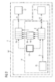
- Fig. 2 is a block diagram illustrating the general structure of an energy management system 1' according to the present invention. Identical or similar components to those in Fig. 1 are designated with the same or corresponding reference numerals. In Fig. 2 , an energy source 15 and a load 17 are shown as components of the overall system, whereas in Fig. 1 these components have not been shown. On the other hand, in Fig. 2 any DC-DC or DC-AC converter components are omitted, please refer to Fig. 3 and details provided further below.
- a supercapacitor block 19 comprising a number of supercapacitors 19i connected in parallel, is a core component.
- a supercap charging unit 8 and a supercap discharging unit 10 are associated to the supercapacitor 19, both the charging and discharging units 8, 10 comprising a "channel" structure corresponding to the structure of block 19 and providing individual charging and discharging operations for each of the supercapacitors 19i.
- an output of the supercap charging unit 8 is connected to the load 17, via the discharging unit 10 and the (first) output 9, and likewise an output of the supercap discharging unit 10 is connected to the battery block 5 via the charging unit 8 and the (second) output 12.
- This second output 12 is also connected to the supercap charging unit 8, which can have an input function, as explained below.
- the arrangement and mutual connections of the supercap charging unit 8, the supercap discharging unit 10, the system battery block 5 and the load 17 are adapted to provide for multiple energy supply paths from the energy source 15 to the system battery block 5 and/or to the load 17, via the supercapacitor block 19, or from the system battery block 5 to the supercapacitor 19 and/or to the load 17, as explained further above in the general part of the description.
- a modified control and monitoring unit 13' is provided for controlling the respective energy flows and, more specifically, the consecutive charging/discharging operations of the supercapacitors 19i, to provide the outstanding system performance.
- the control and monitoring unit 13' can be embodied as an industrial standard PLC and can be equipped with remote control means, both for programming its operation and for implementing at least part of its monitoring functions.
- Such remote control can be implemented both as short-distance remote control, via WLAN or Bluetooth or similar standards, e.g. in home renewable energy applications, and as long-distance remote control, via mobile telecommunications networks, i.e. for implementing distributed renewable energy applications and smart grids.
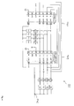
- Fig. 3 shows an electrical energy storing system 101 basically comprising a 12V battery 103, an energy source input 105, a load output 107, a power source step-up/step-down DC-DC converter 109, a 12V/24V DC-DC converter 111, and an energy buffering sub-system 113.
- the energy buffering sub-system 113 comprises n supercapacitors C1... Cn connected between the power input 105 and the load output 107 in parallel, via charging switches SC1...SCn at the input side and discharging switches SD1...SDn at the output side. Additionally, at the output side of each supercapacitor branch, a Schottky diode 115 is provided, for blocking any reverse current flow. A toggle switch TG is provided at the circuit's output, for switching the output voltage between the two predetermined levels 12V or 24V,
- a buffering controller 117 For controlling the operation of the energy buffering sub-system 113, a buffering controller 117 is provided, which delivers control signals for actuating the supercapacitor charging switches SC1 to SCn and discharging switches SD1 to SDn to a capacitors commutator (switch actuator) 119.
- Charging feedback signals A and discharging feedback signals B are provided to respective inputs of the buffering controller 117 from the charging switches block 121 or discharging switches block 123, respectively.
- the buffering controller 117 monitors input (power source) voltages on the one hand and output (load) voltages on the other and controls the charging or discharging switches responsive to the result of a predetermined internal processing of the signals gained through its monitoring function.
- the buffering controller 117 controls the charging switches SC1 to SCn such that, upon application of a sufficient source voltage, charging of the supercapacitors C1 to CQn starts with the first supercapacitor C1, up to a predetermined upper threshold voltage. Once this upper threshold voltage is achieved, the respective charging switch SC1 is opened, immediately followed by closing the second charging switch SC2, associated to the second supercapacitor C2, until the second supercapacitor reaches its upper threshold voltage, and so forth.
- discharging of the supercapacitors starts with actuating the discharging switch SD1 associated to the first supercapacitor C1, until a predetermined lower threshold voltage is reached.
- the first discharging switch SD1 is opened, immediately followed by closing the second discharging switch SD2 to discharge the second supercapacitor C2 to the load, and so forth.
- charging and discharging operations of the supercapacitors are carried out consecutively, i.e. the discharging of one of the supercapacitors down to a predetermined output voltage is immediately followed by starting its recharging up to a predetermined voltage, when at the same time the next one of the supercapacitors is being discharged, and so forth.
- This process will, supposed that no failure appears, continue until the system will powered off or a connected energy source is no longer able to provide a minimum amount of energy (input voltage). In such situation, the buffering sub-system will be waiting until a lower input voltage level is reached, to automatically re-start its operation.
- a corresponding operation scheme can be applied for charging the internal battery 103.
- the battery under 3 can even be charged in parallel to the consecutive charging of the supercapacitors, depending on the implemented specific control scheme, and optionally on a monitor charge/discharge state of the supercapacitors.
- the buffering controller 117 can actuate the charging switches and discharging switches such that the battery 103 is discharged through the output 107, in this way serving as (secondary) energy source for supplying electrical energy to a load connected to the output 107.
- the power source step-up/step-down DC-DC converter 109 provides for a broad range of usable input voltages (6V DC... 32V DC), in a preferred embodiment with an efficiency > 92% and an output current up to 10A.
- the converter 109 comprises a pulse charge controller 25 bidirectionally connected to a conversion monitor 127, which latter is connected to the input 105, in parallel to a switch device 129.
- the switch device 129 provides, at an output SW thereof, a signal to the conversion monitor 127, whereas it receives, besides the voltage applied to the input 105, a control signal from a step-up/step-down DC-DC converter 131.
- the converter 109 comprises a system monitor 133, inputs of which are connected to respective outputs of the controller 131, a current sensor 135 and the power line 137 connecting the input 105 to the supercapacitors C1 to Cn.
- the converter 109 acts on power switches 139 provided in the power line 137. Given that supercapacitors are being used, the maximum voltage of which is 16.2V, the converter output voltage is set to 15.5V, so that the supercapacitors C1 to Cn will charge up to about 15.2V. As far as the detailed operation scheme of the converter 109 is concerned, such type of converters is, as such, none to one of ordinary skill in the art, so that we can refrain from explaining it in more detail.
- the configuration of the 12V/24V DC-DC converter 111 is basically identical to that of the converter 109, i.e. it comprises likewise a pulse charge controller 141, a conversion monitor 143, a switch device 145, a step-up/step-down DC-DC controller 147, and a system monitor 149, and it receives signals from a (second) current sensor 151 and (second) power line 153 and acts on power switches 155.
- the converter 111 is connected to the battery 103, instead of an external energy source, and at its output side it is connected to the system output 107, through the toggle switch TG.
- it can be operated with an efficiency up to 95% and an output current up to 6A.
- Fig. 4 shows a controller structure of the arrangement illustrated in Fig. 3 in more detail.
- the buffering controller 117 comprises a charging controller part 117A and discharging controller part 117B, each part comprising an integrated logic as its core, the signal inputs and outputs IN1 to IN4 and OUT1 to OUT4 of both parts being connected in a feedback manner, to provide for the step-up/step-down operation of the (exemplified four) supercapacitors of the system in the above-explained consecutive operating scheme.
- a charging relay RC1 to RC4 or discharging relay RD1 to RD4 are arranged in each of the respective parallel output lines, connected to a single control signal output 117C.
Landscapes
- Engineering & Computer Science (AREA)
- Power Engineering (AREA)
- Charge And Discharge Circuits For Batteries Or The Like (AREA)
- Electric Propulsion And Braking For Vehicles (AREA)
- Supply And Distribution Of Alternating Current (AREA)
- Stand-By Power Supply Arrangements (AREA)
- Direct Current Feeding And Distribution (AREA)
- Fuel Cell (AREA)
- Medicines Containing Plant Substances (AREA)
Priority Applications (7)
| Application Number | Priority Date | Filing Date | Title |
|---|---|---|---|
| EP11157409.1A EP2498368B1 (de) | 2011-03-09 | 2011-03-09 | System zur Pufferung elektrischer Energie |
| CA2770674A CA2770674C (en) | 2011-03-09 | 2012-03-02 | Electrical energy buffering system |
| SA112330328A SA112330328B1 (ar) | 2011-03-09 | 2012-03-06 | استعمال المستخلص الكحولي للكونينغاميلا كمضاد ميكروبي |
| PCT/IB2012/051119 WO2012120478A1 (en) | 2011-03-09 | 2012-03-09 | Power and hydrogen generator |
| US13/417,081 US9099872B2 (en) | 2011-03-09 | 2012-03-09 | Electrical energy buffering system |
| JP2013557215A JP2014515913A (ja) | 2011-03-09 | 2012-03-09 | 発電及び水素発生器 |
| US14/740,036 US20160072333A1 (en) | 2011-03-09 | 2015-06-15 | Electrical energy buffering system |
Applications Claiming Priority (1)
| Application Number | Priority Date | Filing Date | Title |
|---|---|---|---|
| EP11157409.1A EP2498368B1 (de) | 2011-03-09 | 2011-03-09 | System zur Pufferung elektrischer Energie |
Publications (2)
| Publication Number | Publication Date |
|---|---|
| EP2498368A1 true EP2498368A1 (de) | 2012-09-12 |
| EP2498368B1 EP2498368B1 (de) | 2014-08-06 |
Family
ID=44721163
Family Applications (1)
| Application Number | Title | Priority Date | Filing Date |
|---|---|---|---|
| EP11157409.1A Not-in-force EP2498368B1 (de) | 2011-03-09 | 2011-03-09 | System zur Pufferung elektrischer Energie |
Country Status (6)
| Country | Link |
|---|---|
| US (2) | US9099872B2 (de) |
| EP (1) | EP2498368B1 (de) |
| JP (1) | JP2014515913A (de) |
| CA (1) | CA2770674C (de) |
| SA (1) | SA112330328B1 (de) |
| WO (1) | WO2012120478A1 (de) |
Families Citing this family (7)
| Publication number | Priority date | Publication date | Assignee | Title |
|---|---|---|---|---|
| DE102012215755A1 (de) * | 2012-09-05 | 2014-03-06 | Robert Bosch Gmbh | Niedervoltnetz mit Gleichspannungswandler und Verfahren zum Testen einer Niedervoltbatterie |
| US9543786B2 (en) * | 2013-10-28 | 2017-01-10 | V5 Systems, Inc. | Portable power system |
| DE102014109092A1 (de) * | 2014-06-27 | 2015-12-31 | Thyssenkrupp Ag | Antriebssystem für ein U-Boot |
| US10622823B2 (en) * | 2017-03-28 | 2020-04-14 | The Government Of The United States, As Represented By The Secretary Of The Army | Battery charging and discharging without interface removal |
| WO2020185678A1 (en) * | 2019-03-09 | 2020-09-17 | Cornell University | Switched energy buffering |
| CN113795403A (zh) * | 2019-03-20 | 2021-12-14 | 理查德·赫·谢拉特和苏珊·毕·谢拉特可撤销信托基金 | 使用多线电感器的高能电容变换设备 |
| CN111952079B (zh) * | 2019-05-17 | 2022-04-22 | 清华大学 | 可持续充电的储能装置 |
Citations (5)
| Publication number | Priority date | Publication date | Assignee | Title |
|---|---|---|---|---|
| US20020177018A1 (en) * | 2001-05-23 | 2002-11-28 | Fuglevand William A. | Fuel cell power system, method of distributing power, and method of operating a fuel cell power system |
| US20030214269A1 (en) * | 2002-05-13 | 2003-11-20 | Lih-Ren Shiue | High current pulse generator |
| US20090091302A1 (en) * | 2007-10-04 | 2009-04-09 | Ileana Rusan | Method of charging and discharging of supercapacitors without the use of converters or chargers |
| US20090134851A1 (en) * | 2005-10-19 | 2009-05-28 | Harumi Takeda | Electric power storage system using capacitors and control method thereof |
| US20100060231A1 (en) * | 2006-01-05 | 2010-03-11 | Tpl, Inc. | Method and Apparatus for Energy Harvesting and/or Generation, Storage, and Delivery |
Family Cites Families (14)
| Publication number | Priority date | Publication date | Assignee | Title |
|---|---|---|---|---|
| JPH06124720A (ja) * | 1992-10-10 | 1994-05-06 | Aqueous Res:Kk | ハイブリッド電源装置 |
| US5318142A (en) * | 1992-11-05 | 1994-06-07 | Ford Motor Company | Hybrid drive system |
| JPH1146455A (ja) * | 1997-07-24 | 1999-02-16 | Sekisui Jushi Co Ltd | 太陽電池式電源装置 |
| JP3487780B2 (ja) * | 1999-03-01 | 2004-01-19 | 株式会社岡村研究所 | 接続切り換え制御キャパシタ電源装置 |
| US6252762B1 (en) * | 1999-04-21 | 2001-06-26 | Telcordia Technologies, Inc. | Rechargeable hybrid battery/supercapacitor system |
| US6323623B1 (en) * | 1999-08-23 | 2001-11-27 | Casio Computer Co., Ltd. | Charging device and charging method thereof |
| US6441581B1 (en) * | 2001-03-20 | 2002-08-27 | General Electric Company | Energy management system and method |
| US7427450B2 (en) * | 2004-12-10 | 2008-09-23 | General Motors Corporation | Hybrid fuel cell system with battery capacitor energy storage system |
| JP2008529177A (ja) * | 2005-02-02 | 2008-07-31 | キャップ−エックス・エックス・リミテッド | 電源装置 |
| US8432064B2 (en) * | 2005-10-31 | 2013-04-30 | Ryuji Maeda | System and method for efficient power utilization and extension of battery life |
| JP4572850B2 (ja) * | 2006-03-24 | 2010-11-04 | 株式会社日立製作所 | 電源制御装置 |
| JP4640391B2 (ja) * | 2007-08-10 | 2011-03-02 | トヨタ自動車株式会社 | 電源システムおよびそれを備えた車両 |
| KR101482300B1 (ko) * | 2009-06-15 | 2015-01-14 | 학 혼 차우 | 무정지형 모듈러 배터리 관리 시스템 |
| DE112009005054T5 (de) * | 2009-07-09 | 2012-06-06 | Toyota Jidosha Kabushiki Kaisha | Wandlersteuervorrichtung und Mehrphasenwandler |
-
2011
- 2011-03-09 EP EP11157409.1A patent/EP2498368B1/de not_active Not-in-force
-
2012
- 2012-03-02 CA CA2770674A patent/CA2770674C/en active Active
- 2012-03-06 SA SA112330328A patent/SA112330328B1/ar unknown
- 2012-03-09 JP JP2013557215A patent/JP2014515913A/ja active Pending
- 2012-03-09 WO PCT/IB2012/051119 patent/WO2012120478A1/en active Application Filing
- 2012-03-09 US US13/417,081 patent/US9099872B2/en not_active Expired - Fee Related
-
2015
- 2015-06-15 US US14/740,036 patent/US20160072333A1/en not_active Abandoned
Patent Citations (5)
| Publication number | Priority date | Publication date | Assignee | Title |
|---|---|---|---|---|
| US20020177018A1 (en) * | 2001-05-23 | 2002-11-28 | Fuglevand William A. | Fuel cell power system, method of distributing power, and method of operating a fuel cell power system |
| US20030214269A1 (en) * | 2002-05-13 | 2003-11-20 | Lih-Ren Shiue | High current pulse generator |
| US20090134851A1 (en) * | 2005-10-19 | 2009-05-28 | Harumi Takeda | Electric power storage system using capacitors and control method thereof |
| US20100060231A1 (en) * | 2006-01-05 | 2010-03-11 | Tpl, Inc. | Method and Apparatus for Energy Harvesting and/or Generation, Storage, and Delivery |
| US20090091302A1 (en) * | 2007-10-04 | 2009-04-09 | Ileana Rusan | Method of charging and discharging of supercapacitors without the use of converters or chargers |
Also Published As
| Publication number | Publication date |
|---|---|
| SA112330328B1 (ar) | 2014-11-02 |
| US20160072333A1 (en) | 2016-03-10 |
| CA2770674A1 (en) | 2012-09-09 |
| US9099872B2 (en) | 2015-08-04 |
| WO2012120478A1 (en) | 2012-09-13 |
| WO2012120478A8 (en) | 2012-11-29 |
| EP2498368B1 (de) | 2014-08-06 |
| CA2770674C (en) | 2013-12-03 |
| JP2014515913A (ja) | 2014-07-03 |
| US20120229101A1 (en) | 2012-09-13 |
Similar Documents
| Publication | Publication Date | Title |
|---|---|---|
| CA2770674C (en) | Electrical energy buffering system | |
| US8193761B1 (en) | Hybrid power source | |
| KR102084926B1 (ko) | 배터리 시스템 및 중간 전압 공급 방법 | |
| US8417400B2 (en) | Control system for hybrid vehicles with reconfigurable multi-function power converter | |
| US7768229B2 (en) | Electric car charging systems | |
| KR101084214B1 (ko) | 계통 연계형 전력 저장 시스템 및 전력 저장 시스템 제어 방법 | |
| JP4954335B2 (ja) | 急速充電装置 | |
| JP2021023096A (ja) | 電池充電のためのシステム | |
| CN102422242A (zh) | 控制设备和控制方法 | |
| RU2009116280A (ru) | Устройство источника питания и транспортное средство с устройством источника питания | |
| CN104024968B (zh) | 用于为可再生能源进行电力转换的系统和方法 | |
| CN102549878A (zh) | 切换电路、控制装置及发电系统 | |
| US20170054401A1 (en) | Drive apparatus and transporter | |
| CN102148525A (zh) | 车辆用电源设备 | |
| US8294435B2 (en) | Power supply apparatus supplying power stored in power storage unit to load and power supply system including power supply apparatus | |
| US9257859B2 (en) | Dynamic battery control based on demand | |
| Oriti et al. | Battery management system with cell equalizer for multi-cell battery packs | |
| US20070092763A1 (en) | Fuel cell system | |
| CN110293845B (zh) | 启停电池系统、启停电池控制方法和交通载具 | |
| KR101330349B1 (ko) | 전력 변환 장치 및 이를 이용한 전력 변환 방법 | |
| RU2520180C2 (ru) | Система электропитания транспортного средства | |
| US20170338657A1 (en) | Micro grid stabilization device | |
| Ando et al. | A new super-rapid pulse power charging electric scooter system with balancer-less EDLC stack | |
| WO2018016546A1 (ja) | エネルギ管理装置 | |
| JP2024032227A (ja) | 電力システム及びその制御方法 |
Legal Events
| Date | Code | Title | Description |
|---|---|---|---|
| PUAI | Public reference made under article 153(3) epc to a published international application that has entered the european phase |
Free format text: ORIGINAL CODE: 0009012 |
|
| 17P | Request for examination filed |
Effective date: 20120316 |
|
| AK | Designated contracting states |
Kind code of ref document: A1 Designated state(s): AL AT BE BG CH CY CZ DE DK EE ES FI FR GB GR HR HU IE IS IT LI LT LU LV MC MK MT NL NO PL PT RO RS SE SI SK SM TR |
|
| AX | Request for extension of the european patent |
Extension state: BA ME |
|
| 17Q | First examination report despatched |
Effective date: 20121206 |
|
| GRAP | Despatch of communication of intention to grant a patent |
Free format text: ORIGINAL CODE: EPIDOSNIGR1 |
|
| INTG | Intention to grant announced |
Effective date: 20140210 |
|
| GRAS | Grant fee paid |
Free format text: ORIGINAL CODE: EPIDOSNIGR3 |
|
| GRAA | (expected) grant |
Free format text: ORIGINAL CODE: 0009210 |
|
| AK | Designated contracting states |
Kind code of ref document: B1 Designated state(s): AL AT BE BG CH CY CZ DE DK EE ES FI FR GB GR HR HU IE IS IT LI LT LU LV MC MK MT NL NO PL PT RO RS SE SI SK SM TR |
|
| REG | Reference to a national code |
Ref country code: GB Ref legal event code: FG4D |
|
| REG | Reference to a national code |
Ref country code: CH Ref legal event code: EP Ref country code: AT Ref legal event code: REF Ref document number: 681419 Country of ref document: AT Kind code of ref document: T Effective date: 20140815 |
|
| REG | Reference to a national code |
Ref country code: IE Ref legal event code: FG4D |
|
| REG | Reference to a national code |
Ref country code: DE Ref legal event code: R096 Ref document number: 602011008826 Country of ref document: DE Effective date: 20140918 |
|
| REG | Reference to a national code |
Ref country code: CH Ref legal event code: PCOW Free format text: NEW ADDRESS: 5-1 HIGH MEADOW PLACE, TORONTO, ON M9L 0A3 (CA) |
|
| RAP2 | Party data changed (patent owner data changed or rights of a patent transferred) |
Owner name: NIM ENERGY |
|
| REG | Reference to a national code |
Ref country code: NL Ref legal event code: T3 |
|
| REG | Reference to a national code |
Ref country code: AT Ref legal event code: MK05 Ref document number: 681419 Country of ref document: AT Kind code of ref document: T Effective date: 20140806 |
|
| REG | Reference to a national code |
Ref country code: LT Ref legal event code: MG4D |
|
| PG25 | Lapsed in a contracting state [announced via postgrant information from national office to epo] |
Ref country code: SE Free format text: LAPSE BECAUSE OF FAILURE TO SUBMIT A TRANSLATION OF THE DESCRIPTION OR TO PAY THE FEE WITHIN THE PRESCRIBED TIME-LIMIT Effective date: 20140806 Ref country code: BG Free format text: LAPSE BECAUSE OF FAILURE TO SUBMIT A TRANSLATION OF THE DESCRIPTION OR TO PAY THE FEE WITHIN THE PRESCRIBED TIME-LIMIT Effective date: 20141106 Ref country code: ES Free format text: LAPSE BECAUSE OF FAILURE TO SUBMIT A TRANSLATION OF THE DESCRIPTION OR TO PAY THE FEE WITHIN THE PRESCRIBED TIME-LIMIT Effective date: 20140806 Ref country code: PT Free format text: LAPSE BECAUSE OF FAILURE TO SUBMIT A TRANSLATION OF THE DESCRIPTION OR TO PAY THE FEE WITHIN THE PRESCRIBED TIME-LIMIT Effective date: 20141209 Ref country code: NO Free format text: LAPSE BECAUSE OF FAILURE TO SUBMIT A TRANSLATION OF THE DESCRIPTION OR TO PAY THE FEE WITHIN THE PRESCRIBED TIME-LIMIT Effective date: 20141106 Ref country code: LT Free format text: LAPSE BECAUSE OF FAILURE TO SUBMIT A TRANSLATION OF THE DESCRIPTION OR TO PAY THE FEE WITHIN THE PRESCRIBED TIME-LIMIT Effective date: 20140806 Ref country code: FI Free format text: LAPSE BECAUSE OF FAILURE TO SUBMIT A TRANSLATION OF THE DESCRIPTION OR TO PAY THE FEE WITHIN THE PRESCRIBED TIME-LIMIT Effective date: 20140806 Ref country code: GR Free format text: LAPSE BECAUSE OF FAILURE TO SUBMIT A TRANSLATION OF THE DESCRIPTION OR TO PAY THE FEE WITHIN THE PRESCRIBED TIME-LIMIT Effective date: 20141107 |
|
| PG25 | Lapsed in a contracting state [announced via postgrant information from national office to epo] |
Ref country code: LV Free format text: LAPSE BECAUSE OF FAILURE TO SUBMIT A TRANSLATION OF THE DESCRIPTION OR TO PAY THE FEE WITHIN THE PRESCRIBED TIME-LIMIT Effective date: 20140806 Ref country code: IS Free format text: LAPSE BECAUSE OF FAILURE TO SUBMIT A TRANSLATION OF THE DESCRIPTION OR TO PAY THE FEE WITHIN THE PRESCRIBED TIME-LIMIT Effective date: 20141206 Ref country code: RS Free format text: LAPSE BECAUSE OF FAILURE TO SUBMIT A TRANSLATION OF THE DESCRIPTION OR TO PAY THE FEE WITHIN THE PRESCRIBED TIME-LIMIT Effective date: 20140806 Ref country code: AT Free format text: LAPSE BECAUSE OF FAILURE TO SUBMIT A TRANSLATION OF THE DESCRIPTION OR TO PAY THE FEE WITHIN THE PRESCRIBED TIME-LIMIT Effective date: 20140806 Ref country code: HR Free format text: LAPSE BECAUSE OF FAILURE TO SUBMIT A TRANSLATION OF THE DESCRIPTION OR TO PAY THE FEE WITHIN THE PRESCRIBED TIME-LIMIT Effective date: 20140806 Ref country code: CY Free format text: LAPSE BECAUSE OF FAILURE TO SUBMIT A TRANSLATION OF THE DESCRIPTION OR TO PAY THE FEE WITHIN THE PRESCRIBED TIME-LIMIT Effective date: 20140806 Ref country code: PL Free format text: LAPSE BECAUSE OF FAILURE TO SUBMIT A TRANSLATION OF THE DESCRIPTION OR TO PAY THE FEE WITHIN THE PRESCRIBED TIME-LIMIT Effective date: 20140806 |
|
| REG | Reference to a national code |
Ref country code: FR Ref legal event code: PLFP Year of fee payment: 5 |
|
| PG25 | Lapsed in a contracting state [announced via postgrant information from national office to epo] |
Ref country code: RO Free format text: LAPSE BECAUSE OF FAILURE TO SUBMIT A TRANSLATION OF THE DESCRIPTION OR TO PAY THE FEE WITHIN THE PRESCRIBED TIME-LIMIT Effective date: 20140806 Ref country code: DK Free format text: LAPSE BECAUSE OF FAILURE TO SUBMIT A TRANSLATION OF THE DESCRIPTION OR TO PAY THE FEE WITHIN THE PRESCRIBED TIME-LIMIT Effective date: 20140806 Ref country code: EE Free format text: LAPSE BECAUSE OF FAILURE TO SUBMIT A TRANSLATION OF THE DESCRIPTION OR TO PAY THE FEE WITHIN THE PRESCRIBED TIME-LIMIT Effective date: 20140806 Ref country code: CZ Free format text: LAPSE BECAUSE OF FAILURE TO SUBMIT A TRANSLATION OF THE DESCRIPTION OR TO PAY THE FEE WITHIN THE PRESCRIBED TIME-LIMIT Effective date: 20140806 Ref country code: SK Free format text: LAPSE BECAUSE OF FAILURE TO SUBMIT A TRANSLATION OF THE DESCRIPTION OR TO PAY THE FEE WITHIN THE PRESCRIBED TIME-LIMIT Effective date: 20140806 |
|
| PGFP | Annual fee paid to national office [announced via postgrant information from national office to epo] |
Ref country code: IT Payment date: 20150309 Year of fee payment: 5 Ref country code: NL Payment date: 20150309 Year of fee payment: 5 Ref country code: CH Payment date: 20150313 Year of fee payment: 5 |
|
| REG | Reference to a national code |
Ref country code: DE Ref legal event code: R097 Ref document number: 602011008826 Country of ref document: DE |
|
| PGFP | Annual fee paid to national office [announced via postgrant information from national office to epo] |
Ref country code: FR Payment date: 20150309 Year of fee payment: 5 Ref country code: GB Payment date: 20150304 Year of fee payment: 5 |
|
| PLBE | No opposition filed within time limit |
Free format text: ORIGINAL CODE: 0009261 |
|
| STAA | Information on the status of an ep patent application or granted ep patent |
Free format text: STATUS: NO OPPOSITION FILED WITHIN TIME LIMIT |
|
| 26N | No opposition filed |
Effective date: 20150507 |
|
| PG25 | Lapsed in a contracting state [announced via postgrant information from national office to epo] |
Ref country code: LU Free format text: LAPSE BECAUSE OF FAILURE TO SUBMIT A TRANSLATION OF THE DESCRIPTION OR TO PAY THE FEE WITHIN THE PRESCRIBED TIME-LIMIT Effective date: 20150309 Ref country code: MC Free format text: LAPSE BECAUSE OF FAILURE TO SUBMIT A TRANSLATION OF THE DESCRIPTION OR TO PAY THE FEE WITHIN THE PRESCRIBED TIME-LIMIT Effective date: 20140806 |
|
| PG25 | Lapsed in a contracting state [announced via postgrant information from national office to epo] |
Ref country code: SI Free format text: LAPSE BECAUSE OF FAILURE TO SUBMIT A TRANSLATION OF THE DESCRIPTION OR TO PAY THE FEE WITHIN THE PRESCRIBED TIME-LIMIT Effective date: 20140806 |
|
| REG | Reference to a national code |
Ref country code: IE Ref legal event code: MM4A |
|
| PG25 | Lapsed in a contracting state [announced via postgrant information from national office to epo] |
Ref country code: IE Free format text: LAPSE BECAUSE OF NON-PAYMENT OF DUE FEES Effective date: 20150309 |
|
| PG25 | Lapsed in a contracting state [announced via postgrant information from national office to epo] |
Ref country code: BE Free format text: LAPSE BECAUSE OF FAILURE TO SUBMIT A TRANSLATION OF THE DESCRIPTION OR TO PAY THE FEE WITHIN THE PRESCRIBED TIME-LIMIT Effective date: 20140806 |
|
| REG | Reference to a national code |
Ref country code: CH Ref legal event code: PL |
|
| REG | Reference to a national code |
Ref country code: NL Ref legal event code: MM Effective date: 20160401 |
|
| GBPC | Gb: european patent ceased through non-payment of renewal fee |
Effective date: 20160309 |
|
| PG25 | Lapsed in a contracting state [announced via postgrant information from national office to epo] |
Ref country code: MT Free format text: LAPSE BECAUSE OF FAILURE TO SUBMIT A TRANSLATION OF THE DESCRIPTION OR TO PAY THE FEE WITHIN THE PRESCRIBED TIME-LIMIT Effective date: 20140806 |
|
| REG | Reference to a national code |
Ref country code: FR Ref legal event code: ST Effective date: 20161130 |
|
| PG25 | Lapsed in a contracting state [announced via postgrant information from national office to epo] |
Ref country code: CH Free format text: LAPSE BECAUSE OF NON-PAYMENT OF DUE FEES Effective date: 20160331 Ref country code: LI Free format text: LAPSE BECAUSE OF NON-PAYMENT OF DUE FEES Effective date: 20160331 Ref country code: NL Free format text: LAPSE BECAUSE OF NON-PAYMENT OF DUE FEES Effective date: 20160401 Ref country code: FR Free format text: LAPSE BECAUSE OF NON-PAYMENT OF DUE FEES Effective date: 20160331 Ref country code: GB Free format text: LAPSE BECAUSE OF NON-PAYMENT OF DUE FEES Effective date: 20160309 |
|
| PG25 | Lapsed in a contracting state [announced via postgrant information from national office to epo] |
Ref country code: IT Free format text: LAPSE BECAUSE OF NON-PAYMENT OF DUE FEES Effective date: 20160309 |
|
| PG25 | Lapsed in a contracting state [announced via postgrant information from national office to epo] |
Ref country code: HU Free format text: LAPSE BECAUSE OF FAILURE TO SUBMIT A TRANSLATION OF THE DESCRIPTION OR TO PAY THE FEE WITHIN THE PRESCRIBED TIME-LIMIT; INVALID AB INITIO Effective date: 20110309 Ref country code: SM Free format text: LAPSE BECAUSE OF FAILURE TO SUBMIT A TRANSLATION OF THE DESCRIPTION OR TO PAY THE FEE WITHIN THE PRESCRIBED TIME-LIMIT Effective date: 20140806 |
|
| PG25 | Lapsed in a contracting state [announced via postgrant information from national office to epo] |
Ref country code: TR Free format text: LAPSE BECAUSE OF FAILURE TO SUBMIT A TRANSLATION OF THE DESCRIPTION OR TO PAY THE FEE WITHIN THE PRESCRIBED TIME-LIMIT Effective date: 20140806 |
|
| PG25 | Lapsed in a contracting state [announced via postgrant information from national office to epo] |
Ref country code: MK Free format text: LAPSE BECAUSE OF FAILURE TO SUBMIT A TRANSLATION OF THE DESCRIPTION OR TO PAY THE FEE WITHIN THE PRESCRIBED TIME-LIMIT Effective date: 20140806 |
|
| PG25 | Lapsed in a contracting state [announced via postgrant information from national office to epo] |
Ref country code: AL Free format text: LAPSE BECAUSE OF FAILURE TO SUBMIT A TRANSLATION OF THE DESCRIPTION OR TO PAY THE FEE WITHIN THE PRESCRIBED TIME-LIMIT Effective date: 20140806 |
|
| PGFP | Annual fee paid to national office [announced via postgrant information from national office to epo] |
Ref country code: DE Payment date: 20190402 Year of fee payment: 9 |
|
| REG | Reference to a national code |
Ref country code: DE Ref legal event code: R119 Ref document number: 602011008826 Country of ref document: DE |
|
| PG25 | Lapsed in a contracting state [announced via postgrant information from national office to epo] |
Ref country code: DE Free format text: LAPSE BECAUSE OF NON-PAYMENT OF DUE FEES Effective date: 20201001 |