EP2497977A1 - Shaft seal system - Google Patents
Shaft seal system Download PDFInfo
- Publication number
- EP2497977A1 EP2497977A1 EP12158900A EP12158900A EP2497977A1 EP 2497977 A1 EP2497977 A1 EP 2497977A1 EP 12158900 A EP12158900 A EP 12158900A EP 12158900 A EP12158900 A EP 12158900A EP 2497977 A1 EP2497977 A1 EP 2497977A1
- Authority
- EP
- European Patent Office
- Prior art keywords
- shaft
- mass body
- additional mass
- sealing
- sealing lip
- Prior art date
- Legal status (The legal status is an assumption and is not a legal conclusion. Google has not performed a legal analysis and makes no representation as to the accuracy of the status listed.)
- Granted
Links
Images


Classifications
-
- F—MECHANICAL ENGINEERING; LIGHTING; HEATING; WEAPONS; BLASTING
- F16—ENGINEERING ELEMENTS AND UNITS; GENERAL MEASURES FOR PRODUCING AND MAINTAINING EFFECTIVE FUNCTIONING OF MACHINES OR INSTALLATIONS; THERMAL INSULATION IN GENERAL
- F16J—PISTONS; CYLINDERS; SEALINGS
- F16J15/00—Sealings
- F16J15/002—Sealings comprising at least two sealings in succession
- F16J15/008—Sealings comprising at least two sealings in succession with provision to put out of action at least one sealing; One sealing sealing only on standstill; Emergency or servicing sealings
-
- F—MECHANICAL ENGINEERING; LIGHTING; HEATING; WEAPONS; BLASTING
- F16—ENGINEERING ELEMENTS AND UNITS; GENERAL MEASURES FOR PRODUCING AND MAINTAINING EFFECTIVE FUNCTIONING OF MACHINES OR INSTALLATIONS; THERMAL INSULATION IN GENERAL
- F16J—PISTONS; CYLINDERS; SEALINGS
- F16J15/00—Sealings
- F16J15/16—Sealings between relatively-moving surfaces
- F16J15/164—Sealings between relatively-moving surfaces the sealing action depending on movements; pressure difference, temperature or presence of leaking fluid
-
- F—MECHANICAL ENGINEERING; LIGHTING; HEATING; WEAPONS; BLASTING
- F16—ENGINEERING ELEMENTS AND UNITS; GENERAL MEASURES FOR PRODUCING AND MAINTAINING EFFECTIVE FUNCTIONING OF MACHINES OR INSTALLATIONS; THERMAL INSULATION IN GENERAL
- F16J—PISTONS; CYLINDERS; SEALINGS
- F16J15/00—Sealings
- F16J15/16—Sealings between relatively-moving surfaces
- F16J15/32—Sealings between relatively-moving surfaces with elastic sealings, e.g. O-rings
- F16J15/3296—Arrangements for monitoring the condition or operation of elastic sealings; Arrangements for control of elastic sealings, e.g. of their geometry or stiffness
Definitions
- the invention relates to a shaft sealing system for the arrangement between a shaft rotatable about a shaft shaft and a fixed housing surrounding the shaft, comprising a housing fixed to the stator, at least rotatably to the shaft rotor portion and a circumferential elastic sealing ring with an elastic sealing lip which in a gap between the stator section and the rotor section is arranged and fixed to one of the sections, wherein the sealing lip abuts the opposite section at standstill of the shaft and is spaced on rotation of the shaft to achieve a freedom from contact with this opposite counter section.
- Shaft sealing systems serve the purpose of isolating against each other in the axial direction adjacent environmental regions of the shaft. As a result, for example, the escape of oil or an oil / air mixture from one area to an adjacent area, which should remain free of oil, can be prevented.
- Well-known shaft sealing systems are available both as non-contact and contact-based sealing systems. at contact-loaded sealing systems, which include, for example, shaft seals, the sealing lip is permanently on the opposite the sealing lip rotating counter section, ie the rotor section or the stator section on. Even with very good surface finish, this leads to high wear, especially at high speeds.
- Non-contact shaft sealing systems which are known for example in the form of labyrinth seals, leave a narrow gap between the mutually rotating surfaces, so that the wear can be significantly reduced or avoided.
- a complete seal can not be achieved.
- the system-related gap allows a certain leakage, which can exceed the acceptable level in individual cases.
- Generic shaft sealing systems are designed to operate in contact with the shaft at standstill or low rotational speeds and thus to ensure complete sealing. At higher speeds, however, eliminates the touch contact, so that at these higher speeds of wear is prevented. By a suitable arrangement can be prevented by the centrifugal force effect nevertheless in such systems that during operation fluid can escape through the seal.
- Such a generic shaft seal system is for example from the EP 1 122 472 B1 known.
- the detachment of the sealing lip from the counter section in the case of EP 1 122 472 B1 the stator section, realized in that the sealing lip is designed such that it is separated as a result of the centrifugal force effect to be achieved at high speeds of the counter surface, so the stator. This system has proven itself in the past.
- the object of the invention is to develop a generic shaft seal system to the effect that this ensures a reliable separation of the sealing lip of the opposite section at low shaft diameters and / or even at low rotational speeds, without this being accompanied by the acceptance of a poor seal at a standstill.
- the sealing ring is fixed to the rotor and arranged such that the sealing lip is lifted by a centrifugally induced radial expansion of the stator, wherein at least one radially movable additional mass body is provided, which is arranged and connected to the sealing lip that it exerts a radially outwardly acting force on the sealing lip in a centrifugally force-induced displacement of the additional mass body radially outward, wherein the center of gravity of the additional mass body is spaced radially outwardly from an outwardly facing surface of the sealing lip.
- At least one additional additional mass body is thus provided from a material deviating from the sealing lip material, which is able to enhance the desired centrifugal force effect.
- the additional mass body is used in the singular.
- a plurality of additional mass bodies is provided which, preferably uniformly distributed, are arranged over the circumference.
- it is at least four, in particular preferably at least six inherently rigid additional mass body, which are distributed over the circumference.
- These additional mass body can lead by their design and / or by their arrangement to a significant increase in the centrifugal force effect. With regard to their design, this can be achieved in particular by a relation to the elastomeric material of the sealing ring increased density.
- the centrifugal force which acts thereon can also be doubled. It is therefore advantageous if the additional mass body consists at least predominantly of a material having a density of at least 3 g / cm 3 . In particular, offers itself, the additional mass body to provide a metal or other inorganic material, in particular a mineral or ceramic material.
- the additional mass body according to the invention provided externally, that is arranged radially outside the rotationally symmetrical at standstill sealing lip. Since the centrifugal force increases proportionally with the distance from the axis of rotation, it is preferred if the center of mass of the additional mass body is spaced from the axis of rotation by at least 5%, in particular by at least 10%, more than the contact area of the sealing lip in its state abutting the stator section. In the case of a plurality of additional mass bodies, the mean spacing of the respective center of gravity from the axis of rotation is preferably at least 5% or 10% greater than the distance of the sealing lip from the axis of rotation. Preferred are larger distances.
- the center of gravity of the additional mass body is spaced radially outward from the outer surface of the sealing lip.
- the additional mass body is accordingly designed as at least for the most part external additional mass body, which extends radially outward beyond the outside surface opposite the contact region of the sealing lip.
- the center of gravity is preferably offset by at least 1 mm, in particular preferably by at least 2 mm, furthermore preferably by at least 5 mm outwards.
- the center of gravity is preferably at least 2%, in particular preferably at least 4%, further from the axis of rotation than the surface opposite the contact region of the sealing lip, over which the additional mass body extends.
- the additional mass body is sufficiently secured to the sealing ring itself, can on a separate guide for the additional mass body be waived.
- an external additional mass body according to the invention which is arranged outside of the sealing ring, it may be advantageous if the additional mass body is not only at least indirectly connected to the sealing ring to produce the desired force radially outward, but additionally provided by a rotor portion Guide system is performed, said guide system is preferably adapted to allow a movement of the additional mass body relative to the rotor portion only in one degree of freedom. This makes it possible to design the connection between the additional mass body and the sealing ring particularly simple and yet ensures a secure guidance of the additional mass body.
- such an additional mass body guided separately from the sealing ring can dispense with any completely firm connection with the sealing ring and instead be arranged, for example, such that it lifts off the sealing ring and thus the sealing lip from the stator section merely by virtue of an undercut arrangement by a movement radially outwards.
- the guide system is preferably designed such that it allows the movement of the rotor section only with respect to one degree of freedom.
- the additional mass body is arranged by a link guide linearly movable on the rotor section, wherein it is preferably linearly movable in the radial direction.
- a slotted guide can be realized, for example, by radially aligned bores or grooves which at least partially guide or receive the additional mass body. It is particularly advantageous if the mobility of the additional mass body is limited radially inward, so that the risk is avoided that the additional mass body itself gets into permanent contact with the stator. This can be done, for example, positive fit, for example by means of a stop.
- An alternative regarding the degree of freedom sees in that the additional mass body is articulated pivotably on the rotor, preferably about a tangentially oriented pivot axis. This pivoting mobility can be realized both by a defined joint and by an elastic joint portion.
- a force transmission member is provided between the sealing ring and the additional mass body, which is articulated pivotably on the sealing ring and / or on the additional mass body. This pivoting mobility is realized via a defined joint or due to its elasticity pivotable portion on the power transmission member.
- a plurality of active actuators is provided, which are designed and arranged such that the sealing lip can be displaced from the counterpart section by applying current or a control fluid to the actuators. Furthermore, a control device for controlling the actuation of the actuators with power or the control fluid is provided.
- the position of the sealing lip can be deliberately influenced by means of the active actuators.
- the multiple actuators are arranged in the region of the sealing lip. Preferably, they are distributed on the outside of the sealing lip over its circumference in order to effect a uniform force on the sealing lip radially inward or radially outward.
- the actuators and the sealing lip can be matched to one another in various ways.
- the actuators can act bidirectionally on the sealing lip in such a way that it can either press it against the shaft or detach it from it. However, it can also be designed so that it can act on the sealing lip only in one direction, ie radially inwards or radially outwards. In these cases, the sealing lip must be designed so that it assumes the opposite position without the action of the actuators.
- the sealing lip is to be designed in such a way that it is spaced apart from the shaft, at least when the shaft is rotating.
- the sealing lip is to be designed in such a way that it bears against the sealing lip, at least when the shaft is stationary.
- the actuator may be designed so that it is moved radially outwardly during energization or radially inwardly, being caused by a spring or the like in the absence of energization, a shift in the opposite direction.
- the actuators are preferably components with two mutually movable parts, namely a base for preferably stationary attachment to a housing surrounding the shaft and an actuator member, which in contrast can be displaced by energizing or fluid loading.
- the actuator members such as pressure pins can be pressed against the sealing lip, so that the sealing lip dodges inward.
- an electromagnetically acting actuators are possible, which displaces an active section when energized, which acts on the sealing ring, or is integrated in the sealing ring.
- related designs provide electrostatically acting actuators, piezoelectrically acting actuators or electrostatically acting actuators.
- a fundamentally alternative system for this purpose has actuators with a fluid chamber for receiving the control fluid. With such a configuration, the control device consequently effects a supply of a gaseous or liquid control fluid into the fluid chamber for the targeted achievement of a separation or production of a contact contact between the sealing lip and the counterpart section. Depending on the configuration of this fluid chamber This can be achieved in the desired direction a movement of the sealing lip.
- the control device is preferably adapted to detect the rotational speed of the shaft or this to be supplied by other electronic systems to make the control of the actuator in response to this speed can.
- At least three actuators are provided, in particular six or eight actuators, wherein these are preferably distributed uniformly over the circumference. The more actuators are provided, the less severe is the failure of a single actuator.
- a generic shaft seal system is further developed in that the sealing ring is fixed to the stator and the counterpart is formed by a rotatably fixed to the shaft rotor portion, wherein the counter portion is arranged and formed such that it centrifugally force due to a rotational movement of the shaft the shaft is displaced and thus spaced from the sealing lip.
- the sealing lip is not primarily caused by a displacement in the radial or axial direction, a separation from the counter portion and a surface provided thereon. Instead, it is the mating portion or a portion of it that is displaced to disengage from the sealing lip at a sufficient rotational speed.
- the counterpart section is therefore not completely immovable to the shaft. Although he is rotatable with the shaft or a to Shaft stationary radial flange formed opposite the shaft, however, at least axially or radially movable.
- the rotor portion is axially displaceable relative to the shaft.
- the rotor portion which is formed for abutment with the sealing lip when the shaft is stopped, axially spaced from the sealing lip to effect the contactless.
- at least one radially movable additional mass body is provided, which is operatively connected to the shaft and the rotor portion such that it causes an axial movement of the rotor portion relative to the shaft by a radial movement.
- This additional mass body is at least radially movable, so that it is subjected to centrifugal force depending on the rotational speed of the shaft radially outwardly. By a correspondingly formed active coupling this movement is preferably implemented radially outward in an axial movement of the rotor section.
- This active coupling is preferably achieved in that the additional mass body, preferably about a tangentially oriented axis, is pivotally movable relative to the shaft, wherein on the additional mass body, an effective portion is provided which is in engagement with the rotor portion and axially displaced axially when pivoting the additional mass body becomes.
- the active portion thus operates as a lever whose pivot axis is preferably provided stationary to the shaft. This lever converts the acting on the additional mass body and acting radially outward force in an axial force.
- This embodiment as a lever represents a particularly simple form for producing a radial / axial active coupling.
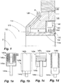
- FIG. 1 shows a first embodiment of a sealing system according to the invention. This is between a shaft 112, which forms the rotor 110 of the system together with a radial flange 114 shown in section, and a fixed housing portion 120, which forms the stator 120 in the context of the invention, application.
- the sealing ring 130 provided for this purpose is fastened to a plate 122 of the stator 120 and is therefore rotationally immovable with respect to a rotation axis 2 of the shaft 112 with respect to this plate 122.
- the sealing ring 130 extends substantially axially, with its radially inward direction side facing a sealing lip 132 is provided, which in the stationary state of FIG. 1 on an outer surface 114a of the radial flange 114 of the rotor.
- an actuator 140 Radially outside of the sealing ring 130, an actuator 140 is shown, which is representative of a plurality of identically arranged circumferentially identical actuators and has a fixedly provided on the stator actuator base 142 and a radially displaceable relative to this actuator base 142 Aktorit 144 has. This actuator pin 144 extends to an outer side of the sealing ring 130.
- the sealing ring 130 has a shape and material condition which is suitable for pressing the sealing lip 132 against a mating surface 114a on the radial flange 114 in the absence of an external application of force by the actuator pin 144.
- the sealing lip prevents in the stationary state by abutment against the mating surface 114a, that oil or an oil / air mixture from a region A, in the intended use of oil, enters a region B, which is intended to remain free of oil.
- Actuator 140 may be configured in various ways to effect a radially outward displacement of actuator pin 144 in response to this energization, or radially inward in alternative configurations.
- the Fig. 1a to 1d show possible embodiments 140a to 140d, wherein the mobility of the Aktorloches is illustrated by dashed lines.
- FIG. 1a shows an exemplary embodiment in which the actuator 140a has a solenoid comprising a coil 146a, which when energized, the actuator pin 144a surrounded by the electromagnet displaced by means of a magnetizable collar 145a, which is provided on the Aktor busy 144a.
- Fig. 1b shows an actuator 140b based on a piezoelectric effect or electrostriction whose actuator base 142b is deformable by the application of current.
- Fig. 1c shows a capacitive actuator having a capacitor plate 147c that can be electrically charged by the controller 148, thereby causing movement of an opposing backplate 145c on the actuator pin 144c.
- the actuator pin 144d can be radially displaced.
- actuators are capable of effecting a movement of the axial pin in the radial direction on the shaft to or from the shaft by current application or fluid loading.
- an additional spring may be provided to support, which causes a movement of the Aktorstattes inward or outward when eliminating the energization or pressurization.
- a plurality of actuators are provided, so that the failure of a single actuator does not affect the functioning or seriously.
- Fig. 1e illustrates an exemplary division of a total of eight actuators 140, which are distributed over the circumference.
- the displacement of the respective actuator pin 144 can press the sealing lip 132 against the shaft or pull it off the shaft 112.
- FIG. 2 show alternative, purely mechanical embodiments of a shaft sealing system according to the invention. It comprises a rotor 210 with a shaft 212 and a circumferential radial flange 214 stationary relative to the shaft 212.
- the rotor 210 is rotatably mounted about a rotation axis 2 relative to a housing and a stator 220 provided thereon.
- the shaft sealing system has a sealing ring 230, which in the case of the embodiments of FIG. 2
- instead of fixed to the rotor 220 rotatably on the rotor 210 and thus rotates together with the rotor relative to the stator 220.
- a sealing lip 232 is provided, which rests in the rest state of the shaft 210 due to the shape of the sealing ring 230 at a right angle or parallel to the rotation axis 2 aligned counter surface 220a of the stator 220.
- 230 additional mass body 250 are disposed near the sealing lip 232 in the sealing ring.
- the additional mass bodies are arranged offset radially outward relative to an outwardly facing surface opposite the sealing lip 230. They are attached to this purpose on webs 252 or integrally formed with these, which in turn are attached to an outer surface on the sealing ring 230 or embedded in these. Since the additional mass bodies 250 of the embodiments of Fig. 2 Metallic, they have a much higher density than the elastomeric material of the sealing ring. The centrifugal force effect is therefore significantly greater than it would be if the additional mass body 250 were omitted. Therefore, a significantly lower rotational speed of the shaft 210 is sufficient to separate the sealing lip 232 from the opposing surface 220a. Thus, a reduction in wear is achieved even at low speeds.
- FIGS. 3a to 3c show a further embodiment of a shaft sealing system according to the invention.
- the shaft sealing system of FIGS. 3a to 3c is provided on a shaft 312 with a radially outwardly facing and fixed to the shaft radial flange 314, which together form the rotor 310 of the system and are rotatable relative to a housing fixedly provided on the stator 320 about the rotation axis 2.
- the sealing ring 330 rotatably provided on the rotor 310 and has a sealing lip 332, which rests at standstill of the shaft 310 on a counter surface 320a of the stator.
- FIGS. 3a to 3c has a plurality of additional mass bodies 350 for improving the centrifugal force effect on the sealing ring 330.
- these additional mass bodies 350 are not in the FIG. 2a shown manner provided directly on or in the sealing ring 330, but arranged as a clearly isolated components in a defined by the radial flange 314 and the sealing ring 330 annular space. It is a much smaller number of additional mass bodies. In the present example, a total of six additional mass bodies 350 are arranged distributed over the circumference. Each of these additional mass bodies 350 combines the vast majority of its mass in a spherical body 352, from which a support rod 354 extends to a pivot joint 356.
- a force transmission member 358 is arranged between the additional mass body 350 and the sealing ring 330, which is located both on the additional mass body 350 and on the distal end of the Sealing ring 330 is hinged pivotally.
- This design results in that a pivotal displacement of the additional mass body 350 to the outside, which occurs at sufficient rotational speeds of the shaft 312 and the in Fig. 3b indicated by dashed lines, indirectly via the force transmission member 358 initiates a radially outwardly acting tensile force in the distal end of the sealing ring 330, through which the sealing lip 332 is lifted radially from the counter surface 320a.
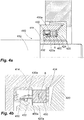
- FIGS. 4a to 4d has a high degree of relationship to the design of the FIGS. 3a to 3c on.
- a radial flange 414 co-rotating with a shaft 412 is provided, on which a sealing ring 430 is fixed with a sealing lip 432.
- the design according to the FIGS. 4a to 4d separate additional mass body 450, which are not integrated into the sealing ring 430.
- These additional mass bodies 450 are in the in Fig. 4c and 4d illustrated manner guided by link guide radially linearly movable.
- a variation, not shown, to said plug connection between the additional mass bodies 450 and the sealing ring 430 does not provide a direct or permanent connection between the additional mass body 450 and the sealing ring 430. Instead, the lifting portion 450a are arranged inside the sealing ring 430, so that a rear engagement is achieved, which ensures a radial deflection of the sealing ring 430 to the outside, as soon as the additional mass bodies are moved radially outwards due to centrifugal force.
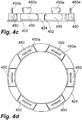
- Fig. 5a and 5b is another principle realized to realize a non-contact seal in the rotational state and a touch-acting seal in a state of standstill.
- the arrangement of these figures comprises a shaft 512 and a radial flange 514, which together form part of a rotor 510.
- This rotor 510 is rotationally movable about the rotation axis 2 a stator 520 to which a sealing ring 530 is attached with a sealing lip 532.
- the rotor 510 has a non-elastic, preferably metallic, annular sealing body 516, which has an opposing surface 516a oriented orthogonally to the axis of rotation for the sealing ring 530.
- This sealing body 516 is pushed onto the radial flange 514 and due to a suitable clearance against this axially movable during operation.
- a rotational mobility between the sealing body 516 on the one hand and the radial flange 514 and the shaft 512 on the other hand is not given.
- the sealing body 516 has an outwardly facing groove 516b. In this groove 516b extending around a radial flange 514 fixed tangential axis 8 pivotable lever 518, at the opposite end of an additional mass body 550 is arranged.
- the sealing body 516 is displaced back to the left under the action of the O-ring 517 acting as a spring and thus comes into contact again with the sealing lip 532.
Abstract
Description
Die Erfindung betrifft ein Wellendichtsystem zur Anordnung zwischen einer um eine Wellenachse drehbaren Welle und einem die Welle umgebenden feststehenden Gehäuse, umfassend einen zum Gehäuse ortsfesten Statorabschnitt, einen zur Welle zumindest drehfesten Rotorabschnitt und einen umlaufenden elastischen Dichtring mit einer elastischen Dichtlippe, der in einem Spalt zwischen dem Statorabschnitt und dem Rotorabschnitt angeordnet und an einem der Abschnitte festgelegt ist, wobei die Dichtlippe bei Stillstand der Welle am gegenüberliegenden Abschnitt anliegt und bei Rotation der Welle zur Erreichung eine Berührungsfreiheit zu diesem gegenüberliegenden Gegenabschnitt beabstandet wird.The invention relates to a shaft sealing system for the arrangement between a shaft rotatable about a shaft shaft and a fixed housing surrounding the shaft, comprising a housing fixed to the stator, at least rotatably to the shaft rotor portion and a circumferential elastic sealing ring with an elastic sealing lip which in a gap between the stator section and the rotor section is arranged and fixed to one of the sections, wherein the sealing lip abuts the opposite section at standstill of the shaft and is spaced on rotation of the shaft to achieve a freedom from contact with this opposite counter section.
Wellendichtsysteme dienen dem Zweck, in Axialrichtung aneinander angrenzende Umgebungsbereiche der Welle gegeneinander zu isolieren. Hierdurch kann beispielsweise der Austritt von Öl oder einem Öl/Luft-Gemisch aus einem Bereich in einen benachbarten Bereich, der frei von Öl bleiben soll, verhindert werden. Bekannte Wellendichtsysteme gibt es sowohl als berührungsfreie und berührungsbehaftete Dichtsysteme. Bei berührungsbehafteten Dichtsystemen, zu denen beispielsweise Wellendichtringe gehören, liegt die Dichtlippe permanent an dem gegenüber der Dichtlippe rotierenden Gegenabschnitt, also dem Rotorabschnitt oder dem Statorabschnitt, an. Selbst bei sehr guter Oberflächenbeschaffenheit führt dies zu einem hohen Verschleiß, insbesondere bei hohen Drehzahlen. Berührungsfreie Wellendichtsysteme, die beispielsweise in der Form von Labyrinthdichtungen bekannt sind, belassen einen schmalen Spalt zwischen den gegeneinander rotierenden Flächen, so dass der Verschleiß deutlich reduziert oder vermieden werden kann. Allerdings ist bei solchen Dichtsystemen keine vollständige Abdichtung zu erzielen. Der systembedingt vorhandene Spalt erlaubt eine gewisse Leckage, die im Einzelfall das akzeptable Maß übersteigen kann.Shaft sealing systems serve the purpose of isolating against each other in the axial direction adjacent environmental regions of the shaft. As a result, for example, the escape of oil or an oil / air mixture from one area to an adjacent area, which should remain free of oil, can be prevented. Well-known shaft sealing systems are available both as non-contact and contact-based sealing systems. at contact-loaded sealing systems, which include, for example, shaft seals, the sealing lip is permanently on the opposite the sealing lip rotating counter section, ie the rotor section or the stator section on. Even with very good surface finish, this leads to high wear, especially at high speeds. Non-contact shaft sealing systems, which are known for example in the form of labyrinth seals, leave a narrow gap between the mutually rotating surfaces, so that the wear can be significantly reduced or avoided. However, in such sealing systems, a complete seal can not be achieved. The system-related gap allows a certain leakage, which can exceed the acceptable level in individual cases.
Gattungsgemäße Wellendichtsysteme sind dafür ausgelegt, bei Stillstand oder geringen Rotationsgeschwindigkeiten der Welle berührungsbehaftet zu arbeiten und somit eine vollständige Abdichtung zu gewährleisten. Bei höheren Drehzahlen hingegen entfällt der Berührkontakt, so dass bei diesen höheren Drehzahlen der Verschleiß verhindert wird. Durch eine geeignete Anordnung kann durch die Zentrifugalkraftwirkung dennoch bei solchen Systemen verhindert werden, dass im Betrieb Fluid durch die Dichtung hindurch austreten kann. Ein derartiges gattungsgemäßes Wellendichtsystem ist beispielsweise aus der
Als problematisch hat sich jedoch herausgestellt, dass bei geringen Drehzahlen und/oder bei geringen Wellendurchmessern nicht die erforderliche Zentrifugalkraft erreicht wird, die für ein zuverlässiges Trennen der Dichtlippe vom Gegenabschnitt erforderlich ist. Die Systeme arbeiten demnach über einen längeren Zeitraum als erwünscht mit hohem Verschleiß an der Dichtlippe. Die Variierung des elastischen Materials des Dichtrings zur Senkung der zum Ablösen erforderlichen Kräfte führt hier nicht zu befriedigenden Ergebnissen, da hierdurch auch die Dichtigkeit im Stillstandszustand beeinträchtigt werden kann.However, it has proven to be problematical that at low speeds and / or at low shaft diameters, the required centrifugal force is not achieved, which ensures reliable separation the sealing lip is required by the counter section. The systems work accordingly over a longer period than desired with high wear on the sealing lip. The variation of the elastic material of the sealing ring to reduce the forces required for detachment does not lead to satisfactory results, as this can also affect the tightness in the stationary state.
Bekannt ist es aus der
Bekannt sind weiterhin auch Wellendichtsysteme mit Aktoren, die zur Verlagerung der Dichtlippe Verwendung finden. So schlägt die
Aufgabe der Erfindung ist es, ein gattungsgemäßes Wellendichtsystem dahingehend weiterzubilden, dass dieses bei geringen Wellendurchmessern und/oder bereits bei geringen Rotationsgeschwindigkeiten ein zuverlässiges Trennen der Dichtlippe vom Gegenabschnitt gewährleistet, ohne dass dies mit der Inkaufnahme einer mangelhaften Abdichtung im Stillstand einhergeht.The object of the invention is to develop a generic shaft seal system to the effect that this ensures a reliable separation of the sealing lip of the opposite section at low shaft diameters and / or even at low rotational speeds, without this being accompanied by the acceptance of a poor seal at a standstill.
Erfindungsgemäß kann dies auf mehrere Arten erreicht werden.According to the invention this can be achieved in several ways.
Gemäß einem ersten Aspekt der Erfindung ist der Dichtring am Rotor festgelegt und derart angeordnet, dass die Dichtlippe durch eine zentrifugalkraftbedingte radiale Aufweitung vom Statorabschnitt aufgehoben wird, wobei mindestens ein radial beweglicher Zusatzmassenkörper vorgesehen ist, der derart angeordnet ist und mit der Dichtlippe verbunden ist, dass er bei einer zentrifugalkraftbedingten Verlagerung des Zusatzmassenkörpers radial nach außen einer radial nach außen wirkenden Kraft auf die Dichtlippe ausübt, wobei der Schwerpunkt des Zusatzmassenkörpers von einer nach außen weisenden Oberfläche der Dichtlippe radial nach außen beabstandet ist.According to a first aspect of the invention, the sealing ring is fixed to the rotor and arranged such that the sealing lip is lifted by a centrifugally induced radial expansion of the stator, wherein at least one radially movable additional mass body is provided, which is arranged and connected to the sealing lip that it exerts a radially outwardly acting force on the sealing lip in a centrifugally force-induced displacement of the additional mass body radially outward, wherein the center of gravity of the additional mass body is spaced radially outwardly from an outwardly facing surface of the sealing lip.
Gemäß dieser ersten Gestaltung ist somit mindestens ein zusätzlicher Zusatzmassenkörper aus einem vom Dichtlippenmaterial abweichenden Material vorgesehen, der in der Lage ist, die gewünschte Zentrifugalkraftwirkung zu verstärken. Im Zusammenhang mit dieser Beschreibung wird der Zusatzmassenkörper im Singular verwendet. Es wird allerdings als vorteilhaft angesehen, wenn eine Mehrzahl von Zusatzmassenkörpern vorgesehen ist, die, vorzugsweise gleichverteilt, über den Umfang angeordnet sind. Vorzugsweise handelt es sich um mindestens vier, insbesondere vorzugsweise mindestens sechs in sich starre Zusatzmassenkörper, die über den Umfang verteilt sind. Diese Zusatzmassenkörper können durch ihre Gestaltung und/oder durch ihre Anordnung zu einer deutlichen Erhöhung der Zentrifugalkraftwirkung führen. Im Hinblick auf ihre Gestaltung kann dies insbesondere durch eine gegenüber dem Elastomermaterial des Dichtrings erhöhte Dichte erzielt werden. Da die Zentrifugalkraft linear mit der Masse steigt, kann beispielsweise mit einer im Mittel durch den Zusatzmassenkörper verdoppelten Masse des Dichtrings auch die Zentrifugalkraft, die auf diesen wirkt, verdoppelt werden. Es ist daher von Vorteil, wenn der Zusatzmassenkörper zumindest überwiegend aus einem Material mit einer Dichte von mindestens 3 g/cm3 besteht. Insbesondere bietet sich an, den Zusatzmassenkörper aus einem Metall oder einem anderen anorganischen Material, insbesondere einem mineralischen oder keramischen Material vorzusehen.According to this first embodiment, at least one additional additional mass body is thus provided from a material deviating from the sealing lip material, which is able to enhance the desired centrifugal force effect. In the context of this description, the additional mass body is used in the singular. However, it is considered advantageous if a plurality of additional mass bodies is provided which, preferably uniformly distributed, are arranged over the circumference. Preferably, it is at least four, in particular preferably at least six inherently rigid additional mass body, which are distributed over the circumference. These additional mass body can lead by their design and / or by their arrangement to a significant increase in the centrifugal force effect. With regard to their design, this can be achieved in particular by a relation to the elastomeric material of the sealing ring increased density. Since the centrifugal force increases linearly with the mass, for example, with a mass of the sealing ring which is doubled on average by the additional mass body, the centrifugal force which acts thereon can also be doubled. It is therefore advantageous if the additional mass body consists at least predominantly of a material having a density of at least 3 g / cm 3 . In particular, offers itself, the additional mass body to provide a metal or other inorganic material, in particular a mineral or ceramic material.
Die Zusatzmassenkörper sind erfindungsgemäß extern vorgesehen, also radial außerhalb der im Stillstand rotationssymmetrischen Dichtlippe angeordnet. Da die Zentrifugalkraft proportional mit dem Abstand von der Drehachse steigt, wird es bevorzugt, wenn der Schwerpunkt des Zusatzmassenkörpers von der Drehachse um mindestens 5%, insbesondere um mindestens 10%, mehr beabstandet ist als der Kontaktbereich der Dichtlippe in ihrem am Statorabschnitt anliegenden Zustand. Im Falle einer Vielzahl von Zusatzmassenkörpern ist die mittlere Beabstandung der jeweiligen Schwerpunkte von der Drehachse vorzugsweise um mindestens 5% bzw. 10% größer als der Abstand der Dichtlippe von der Drehachse. Bevorzugt werden größere Abstände.The additional mass body according to the invention provided externally, that is arranged radially outside the rotationally symmetrical at standstill sealing lip. Since the centrifugal force increases proportionally with the distance from the axis of rotation, it is preferred if the center of mass of the additional mass body is spaced from the axis of rotation by at least 5%, in particular by at least 10%, more than the contact area of the sealing lip in its state abutting the stator section. In the case of a plurality of additional mass bodies, the mean spacing of the respective center of gravity from the axis of rotation is preferably at least 5% or 10% greater than the distance of the sealing lip from the axis of rotation. Preferred are larger distances.
Erfindungsgemäß ist vorgesehen, dass der Schwerpunkt des Zusatzmassenkörpers von der äußeren Oberfläche der Dichtlippe radial nach außen beabstandet ist. Der Zusatzmassenkörper ist demnach als zumindest zum überwiegenden Teil externer Zusatzmassenkörper ausgebildet, der sich über die außenseitige Oberfläche gegenüberliegend des Kontaktbereichs der Dichtlippe radial nach außen erstreckt. Gegenüber der genannten äußeren Oberfläche ist der Schwerpunkt dabei vorzugsweise um zumindest 1 mm, insbesondere vorzugsweise um mindestens 2 mm, weiterhin vorzugsweise um mindestens 5 mm nach außen versetzt. Prozentual gesehen ist der Schwerpunkt vorzugsweise um mindestens 2%, insbesondere vorzugsweise um mindestens 4% weiter von der Drehachse beabstandet als die dem Kontaktbereich der Dichtlippe gegenüberliegede Oberfläche, über die sich der Zusatzmassenkörper erstreckt.According to the invention, it is provided that the center of gravity of the additional mass body is spaced radially outward from the outer surface of the sealing lip. The additional mass body is accordingly designed as at least for the most part external additional mass body, which extends radially outward beyond the outside surface opposite the contact region of the sealing lip. Compared to the said outer surface, the center of gravity is preferably offset by at least 1 mm, in particular preferably by at least 2 mm, furthermore preferably by at least 5 mm outwards. In terms of percentage, the center of gravity is preferably at least 2%, in particular preferably at least 4%, further from the axis of rotation than the surface opposite the contact region of the sealing lip, over which the additional mass body extends.
Wenn der Zusatzmassenkörper am Dichtring selbst ausreichend befestigt ist, kann auf eine separate Führung für den Zusatzmassenkörper verzichtet werden. Bei einem erfindungsgemäßen externen Zusatzmassenkörper, der außerhalb des Dichtrings angeordnet ist, kann es jedoch von Vorteil sein, wenn der Zusatzmassenkörper nicht nur zumindest mittelbar mit dem Dichtring verbunden ist, um die gewünschte Kraftwirkung radial nach außen zu erzeugen, sondern zusätzlich durch ein am Rotorabschnitt vorgesehenes Führungssystem geführt ist, wobei dieses Führungssystem vorzugsweise dafür ausgebildet ist, eine Bewegung des Zusatzmassenkörpers gegenüber dem Rotorabschnitt nur hinsichtlich eines Freiheitsgrades zuzulassen. Dies gestattet es, die Verbindung zwischen dem Zusatzmassenkörper und dem Dichtring besonders einfach auszugestalten und gewährleistet dennoch eine sichere Führung des Zusatzmassenkörpers. Insbesondere kann ein solcher separat vom Dichtring geführter Zusatzmassenkörper auf jegliche vollständig feste Verbindung mit dem Dichtring verzichten und stattdessen beispielsweise derart angeordnet sein, dass er lediglich aufgrund einer Hinterschneidungsanordnung durch eine Bewegung radial nach außen den Dichtring und damit die Dichtlippe vom Statorabschnitt abhebt.If the additional mass body is sufficiently secured to the sealing ring itself, can on a separate guide for the additional mass body be waived. In an external additional mass body according to the invention, which is arranged outside of the sealing ring, it may be advantageous if the additional mass body is not only at least indirectly connected to the sealing ring to produce the desired force radially outward, but additionally provided by a rotor portion Guide system is performed, said guide system is preferably adapted to allow a movement of the additional mass body relative to the rotor portion only in one degree of freedom. This makes it possible to design the connection between the additional mass body and the sealing ring particularly simple and yet ensures a secure guidance of the additional mass body. In particular, such an additional mass body guided separately from the sealing ring can dispense with any completely firm connection with the sealing ring and instead be arranged, for example, such that it lifts off the sealing ring and thus the sealing lip from the stator section merely by virtue of an undercut arrangement by a movement radially outwards.
Wie erwähnt, ist das Führungssystem dabei vorzugsweise derart ausgebildet, dass es die Bewegung des Rotorabschnittes lediglich hinsichtlich eines Freiheitsgrades zulässt. Dies kann bei einer bevorzugten Weiterbildung dadurch realisiert sein, dass der Zusatzmassenkörper durch eine Kulissenführung linearbeweglich am Rotorabschnitt angeordnet ist, wobei er vorzugsweise in Radialrichtung linearbeweglich ist. Eine solche Kulissenführung kann beispielsweise durch radial ausgerichtete Bohrungen oder Nuten, die den Zusatzmassenkörper zumindest teilweise führen oder aufnehmen, realisiert sein. Von besonderem Vorteil ist es dabei, wenn die Beweglichkeit des Zusatzmassenkörpers radial nach innen limitiert ist, so dass die Gefahr vermieden wird, dass der Zusatzmassenkörper selbst in permanenten Berührkontakt mit dem Stator gelangt. Dies kann beispielsweise formschlüssig erfolgen, zum Beispiel mittels eines Anschlags. Eine Alternative hinsichtlich des Freiheitsgrades sieht vor, dass der Zusatzmassenkörper schwenkbeweglich am Rotor angelenkt ist, vorzugsweise um eine tangential ausgerichtete Schwenkachse. Diese Schwenkbeweglichkeit kann sowohl durch ein definiertes Gelenk als auch durch einen elastischen Gelenkabschnitt realisiert sein.As mentioned, the guide system is preferably designed such that it allows the movement of the rotor section only with respect to one degree of freedom. This can be realized in a preferred development in that the additional mass body is arranged by a link guide linearly movable on the rotor section, wherein it is preferably linearly movable in the radial direction. Such a slotted guide can be realized, for example, by radially aligned bores or grooves which at least partially guide or receive the additional mass body. It is particularly advantageous if the mobility of the additional mass body is limited radially inward, so that the risk is avoided that the additional mass body itself gets into permanent contact with the stator. This can be done, for example, positive fit, for example by means of a stop. An alternative regarding the degree of freedom sees in that the additional mass body is articulated pivotably on the rotor, preferably about a tangentially oriented pivot axis. This pivoting mobility can be realized both by a defined joint and by an elastic joint portion.
Weiterhin ist es vorteilhaft, wenn zwischen dem Dichtring und dem Zusatzmassenkörper ein Kraftübertragungsglied vorgesehen ist, welches am Dichtring und/oder am Zusatzmassenkörper schwenkbeweglich angelenkt ist. Auch diese Schwenkbeweglichkeit ist über ein definiertes Gelenk oder einen aufgrund seiner Elastizität schwenkbeweglichen Abschnitt am Kraftübertragungsglied realisierbar.Furthermore, it is advantageous if a force transmission member is provided between the sealing ring and the additional mass body, which is articulated pivotably on the sealing ring and / or on the additional mass body. This pivoting mobility is realized via a defined joint or due to its elasticity pivotable portion on the power transmission member.
Ein besonderer Vorteil ergibt sich in der Kombination der genannten Merkmale, wenn der Zusatzmassenkörper schwenkbeweglich am Rotorabschnitt angeordnet ist, wobei der Schwerpunkt des Zusatzmassenkörpers bezogen auf den Rotorabschnitt jenseits der Schwenkanlenkung des Kraftübertragungsgliedes angeordnet ist. In einem solchen Falle wirkt der Abschnitt des Zusatzmassenkörpers zwischen dem Rotorabschnitt und dem Schwerpunkt des Zusatzmassenkörpers als Hebel, an dem das Kraftübertragungsglied angeordnet ist. Hierdurch kann mit einer vergleichsweise kleinen Masse des Zusatzmassenkörpers zuverlässig die Trennung der Dichtlippe vom Rotorabschnitt erzielt werden.A particular advantage results in the combination of the features mentioned, when the additional mass body is pivotally mounted on the rotor section, wherein the center of gravity of the additional mass body is disposed relative to the rotor section beyond the Schwenkanlenkung of the power transmission member. In such a case, the portion of the additional mass body between the rotor portion and the center of gravity of the additional mass body acts as a lever on which the force transmission member is arranged. As a result, the separation of the sealing lip from the rotor section can be reliably achieved with a comparatively small mass of the additional mass body.
Gemäß einem zweiten Aspekt der Erfindung ist bei einem gattungsgemäßen Wellendichtsystem vorgesehen, dass eine Mehrzahl von aktiven Aktoren vorgesehen ist, die derart ausgebildet und angeordnet sind, dass durch Beaufschlagung der Aktoren mit Strom oder einem Steuerfluid die Dichtlippe gegenüber dem Gegenabschnitt verlagerbar ist. Weiterhin ist eine Steuereinrichtung zur Steuerung der Beaufschlagung der Aktoren mit Strom oder dem Steuerfluid vorgesehen.According to a second aspect of the invention, it is provided in a generic shaft sealing system that a plurality of active actuators is provided, which are designed and arranged such that the sealing lip can be displaced from the counterpart section by applying current or a control fluid to the actuators. Furthermore, a control device for controlling the actuation of the actuators with power or the control fluid is provided.
Bei einer solchen Gestaltung kann auf die Lage der Dichtlippe mittels der aktiven Aktoren gezielt Einfluss genommen werden.With such a design, the position of the sealing lip can be deliberately influenced by means of the active actuators.
Die mehreren Aktoren sind dabei im Bereich der Dichtlippe angeordnet. Vorzugsweise sind sie außenseitig der Dichtlippe über deren Umfang verteilt, um eine gleichmäßige Kraftwirkung auf die Dichtlippe radial nach innen oder radial nach außen bewirken zu können.The multiple actuators are arranged in the region of the sealing lip. Preferably, they are distributed on the outside of the sealing lip over its circumference in order to effect a uniform force on the sealing lip radially inward or radially outward.
Die Aktoren und die Dichtlippe können auf verschiedene Art aufeinander abgestimmt sein. Die Aktoren können bidirektional derart auf die Dichtlippe wirken, dass sie diese entweder an die Welle andrücken oder von dieser lösen kann. Er kann jedoch auch so ausgebildet sein, dass er nur in eine Richtung, also radial nach innen oder radial nach außen, auf die Dichtlippe wirken kann. In diesen Fällen ist die Dichtlippe so auszugestalten, dass sie ohne Einwirkung der Aktoren jeweils die gegensätzliche Position einnimmt. Bei Aktoren, der die Dichtlippe radial nach innen kraftbeaufschlagen können, ist die Dichtlippe so auszubilden, dass sie - zumindest bei drehender Welle - von der Welle beabstandet ist. Bei einem Aktor, der die Dichtlippe nach außen kraftbeaufschlagen kann, ist die Dichtlippe so auszubilden, dass sie - zumindest bei stehender Welle - an der Dichtlippe anliegt. Weiterhin bestehen Variationsmöglichkeiten hinsichtlich der Festlegung, welche Bewegungsrichtung der Aktor bei Bestromung oder Beaufschlagung mit einem Steuerfluid durchführt. So kann beispielsweise unabhängig von der oben genannten Art der Wirkungsweise der Aktor so ausgebildet sein, dass er bei Bestromung radial nach außen oder aber radial nach innen bewegt wird, wobei durch eine Feder oder dergleichen bei Wegfall der Bestromung eine Verlagerung in entgegengesetzte Richtung bewirkt wird.The actuators and the sealing lip can be matched to one another in various ways. The actuators can act bidirectionally on the sealing lip in such a way that it can either press it against the shaft or detach it from it. However, it can also be designed so that it can act on the sealing lip only in one direction, ie radially inwards or radially outwards. In these cases, the sealing lip must be designed so that it assumes the opposite position without the action of the actuators. In the case of actuators, which can apply force to the sealing lip radially inwards, the sealing lip is to be designed in such a way that it is spaced apart from the shaft, at least when the shaft is rotating. In the case of an actuator which can apply force to the outside of the sealing lip, the sealing lip is to be designed in such a way that it bears against the sealing lip, at least when the shaft is stationary. Furthermore, there are variations with regard to determining which direction of movement of the actuator performs when energized or applied with a control fluid. Thus, for example, independently of the above-mentioned type of operation, the actuator may be designed so that it is moved radially outwardly during energization or radially inwardly, being caused by a spring or the like in the absence of energization, a shift in the opposite direction.
Von Vorteil ist eine Anordnung, bei der die Bestromung zur Trennung der Dichtlippe vom Gegenabschnitt führt, da bei einer solchen Gestaltung im Störungsfalle und bei in Folge dessen entfallender Bestromung der Aktoren die Dichtigkeit des Wellendichtsystems gewährleistet ist. Bei den Aktoren handelt es sich vorzugsweise um Komponenten mit zwei geführt gegeneinander beweglichen Teilen, nämlich einer Basis zur vorzugsweise ortsfesten Anbringung an einem die Welle umgebenden Gehäuse und einem Aktorglied, welches demgegenüber durch Bestromung oder Fluidbeaufschlagung verlagerbar ist. Bei von außen auf die Dichtlippe wirkenden Aktoren können die Aktorglieder wie beispielsweise Druckstifte gegen die Dichtlippe gedrückt werden, so dass die Dichtlippe nach innen ausweicht.An advantage is an arrangement in which the energization leads to the separation of the sealing lip from the counter portion, as in such a design In the case of failure and in consequence of which no supply of current to the actuators, the tightness of the shaft sealing system is ensured. The actuators are preferably components with two mutually movable parts, namely a base for preferably stationary attachment to a housing surrounding the shaft and an actuator member, which in contrast can be displaced by energizing or fluid loading. When acting on the outside of the sealing lip actuators, the actuator members such as pressure pins can be pressed against the sealing lip, so that the sealing lip dodges inward.
Während bei dem ersten Aspekt der Erfindung aufgrund der Nutzung der Zentrifugalkraft zwingend vorgesehen ist, dass die Festlegung des Dichtrings am Rotor erfolgt, ist es bei dieser zweiten erfindungsgemäßen Gestaltung grundsätzlich beliebig, ob die Aktoren und der Dichtring am Rotor oder am Stator festgelegt sind. Von Vorteil ist jedoch eine Anordnung des Dichtrings und des Aktors am Stator, da dadurch die Zuführung von Strom oder einem Steuerfluid deutlich erleichtert ist.While in the first aspect of the invention due to the use of centrifugal force is mandatory that the determination of the sealing ring on the rotor, it is in principle arbitrary in this second inventive design, whether the actuators and the sealing ring on the rotor or on the stator are fixed. However, an advantage of an arrangement of the sealing ring and the actuator on the stator, since the supply of electricity or a control fluid is significantly facilitated.
Als aktive Aktoren bieten sich für die erfindungsgemäße Gestaltung mehrere Möglichkeiten an. So sind ein elektromagnetisch wirkende Aktoren möglich, die bei Bestromung einen Wirkabschnitt verlagert, der auf den Dichtring wirkt, oder in den Dichtring integriert ist. Hierzu verwandte Gestaltungen sehen elektrostatisch wirkende Aktoren, piezoelektrisch wirkende Aktoren oder elektrostiktiv wirkende Aktoren vor. Ein grundsätzlich alternatives System hierzu verfügt über Aktoren mit einer Fluidkammer zur Aufnahme des Steuerfluids. Bei einer solchen Gestaltung bewirkt die Steuereinrichtung demzufolge zur gezielten Erreichung einer Trennung oder einer Herstellung eines Berührkontaktes zwischen Dichtlippe und Gegenabschnitt eine Zuführung eines gasförmigen oder flüssigen Steuerfluids in die Fluidkammer. Je nach Ausgestaltung dieser Fluidkammer kann hierdurch eine Bewegung der Dichtlippe in die gewünschte Richtung erzielt werden.As active actuators, several possibilities are available for the design according to the invention. Thus, an electromagnetically acting actuators are possible, which displaces an active section when energized, which acts on the sealing ring, or is integrated in the sealing ring. For this purpose, related designs provide electrostatically acting actuators, piezoelectrically acting actuators or electrostatically acting actuators. A fundamentally alternative system for this purpose has actuators with a fluid chamber for receiving the control fluid. With such a configuration, the control device consequently effects a supply of a gaseous or liquid control fluid into the fluid chamber for the targeted achievement of a separation or production of a contact contact between the sealing lip and the counterpart section. Depending on the configuration of this fluid chamber This can be achieved in the desired direction a movement of the sealing lip.
Da bei der Gestaltung gemäß dem zweiten Aspekt der Erfindung in oben beschriebener Weise der mechanische Automatismus nicht gegeben ist, der bei hohen Drehzahlen zu einer Trennung der Dichtlippe zum Gegenabschnitt führt, ist die Steuereinrichtung vorzugsweise dafür ausgebildet, die Drehzahl der Welle zu erfassen bzw. diese von anderweitigen elektronischen Systemen zugeführt zu bekommen, um die Steuerung des Aktors in Abhängigkeit dieser Drehzahl vornehmen zu können.Since in the design according to the second aspect of the invention in the manner described above, the mechanical automatism is not given, which leads at high speeds to a separation of the sealing lip to the counter portion, the control device is preferably adapted to detect the rotational speed of the shaft or this to be supplied by other electronic systems to make the control of the actuator in response to this speed can.
Vorzugsweise sind mindestens drei Aktoren vorgesehen, insbesondere sechs oder acht Aktoren, wobei diese vorzugsweise gleichmäßig über den Umfang verteilt sind. Je mehr Aktoren vorgesehen sind, desto weniger schwer wiegt der Ausfall eines einzelnen Aktors.Preferably, at least three actuators are provided, in particular six or eight actuators, wherein these are preferably distributed uniformly over the circumference. The more actuators are provided, the less severe is the failure of a single actuator.
Bei einer weiteren Variante der Erfindung ist eine gattungsgemäßes Wellendichtsystem dahingehend weitergebildet, dass der Dichtring am Stator festgelegt ist und der Gegenabschnitt einen durch zur Welle drehfesten Rotorabschnitt gebildet wird, wobei der Gegenabschnitt derart angeordnet und ausgebildet ist, dass er bei einer Drehbewegung der Welle zentrifugalkraftbedingt gegenüber der Welle verlagert wird und somit von der Dichtlippe beabstandet wird.In a further variant of the invention, a generic shaft seal system is further developed in that the sealing ring is fixed to the stator and the counterpart is formed by a rotatably fixed to the shaft rotor portion, wherein the counter portion is arranged and formed such that it centrifugally force due to a rotational movement of the shaft the shaft is displaced and thus spaced from the sealing lip.
Bei dieser Variante ist somit vorgesehen, dass nicht primär die Dichtlippe durch eine Verlagerung in radialer oder axialer Richtung eine Trennung vom Gegenabschnitt und einer an diesem vorgesehenen Fläche bewirkt. Stattdessen ist es der Gegenabschnitt oder ein Teil dessen, der verlagert wird, um sich von der Dichtlippe bei ausreichender Rotationsgeschwindigkeit zu lösen. Der Gegenabschnitt ist daher nicht vollständig unbeweglich zur Welle. Er ist zwar drehfest mit der Welle oder einem zur Welle ortsfesten Radialflansch ausgebildet, gegenüber der Welle jedoch zumindest axial oder radial beweglich.In this variant, it is thus provided that the sealing lip is not primarily caused by a displacement in the radial or axial direction, a separation from the counter portion and a surface provided thereon. Instead, it is the mating portion or a portion of it that is displaced to disengage from the sealing lip at a sufficient rotational speed. The counterpart section is therefore not completely immovable to the shaft. Although he is rotatable with the shaft or a to Shaft stationary radial flange formed opposite the shaft, however, at least axially or radially movable.
Konstruktiv vorteilhaft ist eine Gestaltung, bei der der Rotorabschnitt axial gegenüber der Welle verlagerbar ist. In einem solchen Fall ist der Rotorabschnitt, der zum Anliegen an der Dichtlippe bei Stillstand der Welle ausgebildet ist, axial von der Dichtlippe beabstandbar, um die Berührungslosigkeit zu bewirken. Dabei ist vorzugsweise vorgesehen, dass mindestens ein radial beweglicher Zusatzmassenkörper vorgesehen ist, der derart mit der Welle und dem Rotorabschnitt wirkverbunden ist, dass er durch eine radiale Bewegung eine axiale Bewegung der Rotorabschnitts gegenüber der Welle bewirkt. Dieser Zusatzmassenkörper ist zumindest auch radial beweglich, so dass er in Abhängigkeit der Rotationsgeschwindigkeit der Welle zentrifugalkraftbedingt radial nach außen kraftbeaufschlagt ist. Durch eine entsprechend ausgebildete Wirkkopplung wird diese Bewegung radial nach außen vorzugsweise umgesetzt in eine Axialbewegung des Rotorabschnittes.Constructively advantageous is a design in which the rotor portion is axially displaceable relative to the shaft. In such a case, the rotor portion, which is formed for abutment with the sealing lip when the shaft is stopped, axially spaced from the sealing lip to effect the contactless. In this case, it is preferably provided that at least one radially movable additional mass body is provided, which is operatively connected to the shaft and the rotor portion such that it causes an axial movement of the rotor portion relative to the shaft by a radial movement. This additional mass body is at least radially movable, so that it is subjected to centrifugal force depending on the rotational speed of the shaft radially outwardly. By a correspondingly formed active coupling this movement is preferably implemented radially outward in an axial movement of the rotor section.
Diese Wirkkopplung wird vorzugsweise dadurch erzielt, dass der Zusatzmassenkörper, vorzugsweise um eine tangential ausgerichtete Achse, schwenkbar gegenüber der Welle beweglich ist, wobei am Zusatzmassenkörper ein Wirkabschnitt vorgesehen ist, der sich im Eingriff mit dem Rotorabschnitt befindet und der bei Verschwenken der Zusatzmassenkörpers abschnittsweise axial verlagert wird. Der Wirkabschnitt arbeitet somit als Hebel, dessen Schwenkachse vorzugsweise ortsfest zur Welle vorgesehen ist. Dieser Hebel setzt die auf den Zusatzmassenkörper wirkende und radial nach außen wirkende Kraft in eine Axialkraft um. Diese Ausgestaltung als Hebel stellt eine besonders einfach Form zur Herstellung einer Radial/Axial-Wirkkopplung dar.This active coupling is preferably achieved in that the additional mass body, preferably about a tangentially oriented axis, is pivotally movable relative to the shaft, wherein on the additional mass body, an effective portion is provided which is in engagement with the rotor portion and axially displaced axially when pivoting the additional mass body becomes. The active portion thus operates as a lever whose pivot axis is preferably provided stationary to the shaft. This lever converts the acting on the additional mass body and acting radially outward force in an axial force. This embodiment as a lever represents a particularly simple form for producing a radial / axial active coupling.
Weitere Aspekte und Vorteile der Erfindung ergeben sich außer aus den Ansprüchen auch aus den nachfolgend beschriebenen Ausführungsbeispielen zu dieser Erfindung. Dabei zeigen:
- Fig. 1 und 1a - 1e
- ein erstes Ausführungsbeispiel eines erfindungsgemäßen Wellendichtsystems,
- Fig. 2
- eine zweite und eine dritte Ausführungsform eines erfindungsgemäßen Wellendichtsystems,
- Figur 3a bis 3c
- eine vierte Ausführungsform eines erfindungsgemäßen Dichtsystems,
- Figur 4a bis 4d
- eine vierte Ausführungsform eines erfindungsgemäßen Dichtsystems und
- Figur 5a und 5b
- eine fünfte Ausführungsform eines erfindungsgemäßen Dichtsystems.
- Fig. 1 and 1a - 1e
- A first embodiment of a shaft sealing system according to the invention,
- Fig. 2
- a second and a third embodiment of a shaft sealing system according to the invention,
- FIGS. 3a to 3c
- A fourth embodiment of a sealing system according to the invention,
- FIGS. 4a to 4d
- a fourth embodiment of a sealing system according to the invention and
- FIGS. 5a and 5b
- A fifth embodiment of a sealing system according to the invention.
Der Dichtring 130 weist eine Formgebung und Materialbeschaffenheit auf, die geeignet ist, bei Nichtvorliegen einer externen Kraftbeaufschlagung durch den Aktorenstift 144 die Dichtlippe 132 gegen eine Gegenfläche 114a am Radialflansch 114 zu drücken. Somit kann bei Stillstand der Welle 112 auf eine Einflussnahme des Aktors 140 verzichtet werden. Die Dichtlippe verhindert im Stillstandszustand durch Anliegen an der Gegenfläche 114a, dass Öl oder ein Öl/Luft-Gemisch aus einem Bereich A, in dem bestimmungsgemäß Öl vorgesehen ist, in einen Bereich B gelangt, der bestimmungsgemäß frei von Öl bleiben soll.The sealing
Sobald die Welle in Rotation versetzt wird, wird mittels einer Steuereinrichtung 148, die in
Der Aktor 140 kann in verschiedener Art und Weise gestaltet sein, um in Reaktion auf diese Bestromung eine Verlagerung des Aktorstiftes 144 radial nach außen oder bei alternativen Gestaltungen radial nach innen zu bewirken. Die
Alle Aktortypen sind in der Lage, durch Strombeaufschlagung bzw. Fluidbeaufschlagung eine Bewegung des Axialstiftes in radialer Richtung auf die Welle zu oder von der Welle weg zu bewirken. Bei nicht dargestellten Ausführungsformen kann jedoch zur Unterstützung auch eine zusätzliche Feder vorgesehen sein, die bei Wegfall der Bestromung oder Druckbeaufschlagung eine Bewegung des Aktorstiftes nach innen oder außen bewirkt.All types of actuators are capable of effecting a movement of the axial pin in the radial direction on the shaft to or from the shaft by current application or fluid loading. In embodiments not shown, however, an additional spring may be provided to support, which causes a movement of the Aktorstiftes inward or outward when eliminating the energization or pressurization.
Erfindungsgemäß sind mehrere Aktoren vorgesehen, so dass der Ausfall eines einzelnen Aktors die Funktionsweise nicht oder nicht gravierend beeinträchtigt.
Diese Ausgestaltungen arbeiten hinsichtlich der Herstellung und der Aufhebung des Berührkontaktes zwischen der Dichtlippe 232 und der Gegenfläche 220a rein mechanisch. Sobald die Drehgeschwindigkeit der Welle 210 gegenüber dem Stator 220 ausreichend hoch ist, wird der Dichtring 230 und mit ihm die Dichtlippe 232 aufgrund der Zentrifugalkraft nach außen gedrückt, wobei der Berührkontakt zwischen der Dichtlippe 232 und der Gegenfläche 220a verloren geht.These embodiments operate purely mechanically with respect to the production and the cancellation of the contact between the sealing
Um diesen Effekt zu vergrößern, sind nahe der Dichtlippe 232 im Dichtring 230 Zusatzmassenkörper 250 angeordnet.To increase this effect, 230 additional
Die Zusatzmassenkörper sind dabei radial nach außen versetzt gegenüber einer nach außen weisenden Oberfläche gegenüberliegend der Dichtlippe 230 angeordnet. Sie sind zu diesem Zweck an Stegen 252 angebracht oder mit diesen einstückig ausgebildet, die ihrerseits an einer außenliegenden Oberfläche am Dichtring 230 befestigt sind oder in diesen eingebettet sind. Da die Zusatzmassenkörpern 250 der Ausgestaltungen der
Die
Auch das System der
Die Ausgestaltung der
Bei der Ausgestaltung der
Die Besonderheit dieser Ausgestaltung liegt darin, dass der Rotor 510 einen nichtelastischen, vorzugsweise metallischen, ringförmigen Dichtkörper 516 aufweist, der über eine orthogonal zur Drehachse ausgerichtete Gegenfläche 516a für den Dichtring 530 verfügt. Dieser Dichtkörper 516 ist auf den Radialflansch 514 aufgeschoben und aufgrund einer geeigneten Spielpassung gegenüber diesem auch im Betrieb axial beweglich. Eine Drehbeweglichkeit zwischen dem Dichtkörper 516 einerseits und dem Radialflansch 514 und der Welle 512 andererseits ist dagegen nicht gegeben. Der Dichtkörper 516 verfügt über eine nach außen weisende Nut 516b. In diese Nut 516b erstreckt sich ein um eine zum Radialflansch 514 ortsfeste Tangentialachse 8 schwenkbarer Hebel 518, an dessen gegenüberliegendem Ende eine Zusatzmassenkörper 550 angeordnet ist.The peculiarity of this embodiment is that the
Diese Anordnung bewirkt, dass auf den Zusatzmassenkörper 550 in Abhängigkeit der Rotationsgeschwindigkeit eine nach außen gerichtete Zentrifugalkraft wirkt, die bezogen auf die Darstellung der
Sobald die Rotationsgeschwindigkeit wieder ausreichend abgesenkt wurde, wird der Dichtkörper 516 unter der Wirkung des als Feder agierenden O-Rings 517 zurück nach links verlagert und gelangt so wieder in Berührkontakt mit der Dichtlippe 532.As soon as the rotational speed has again been sufficiently lowered, the sealing
Claims (14)
dadurch gekennzeichnet, dass
der Dichtring (230; 330; 430) am Rotor (210; 310; 410) festgelegt ist und derart angeordnet ist, dass die Dichtlippe (232; 332; 432) bei einer Drehbewegung der Welle (212; 312; 412) durch eine zentrifugalkraftbedingte radiale Aufweitung vom Statorabschnitt (220; 320; 420) abgehoben wird, wobei mindestens ein radial beweglicher Zusatzmassenkörper (250; 350; 450) vorgesehen ist, der derart angeordnet und mit der Dichtlippe (232; 332; 432) wirkverbunden ist, dass er bei einer zentrifugalkraftbedingten Verlagerung radial nach außen eine radial nach außen wirkende Kraft auf die Dichtlippe (232; 332; 432) ausübt, wobei der Schwerpunkt des Zusatzmassenkörpers von einer nach außen weisenden Oberfläche der Dichtlippe radial nach außen beabstandet ist.
characterized in that
the sealing ring (230; 330; 430) is fixed to the rotor (210; 310; 410) and arranged such that the sealing lip (232; 332; 432) upon rotation of the shaft (212; 312; 412) by a centrifugal force At least one radially movable additional mass body (250; 350; 450) is provided, which is arranged and operatively connected to the sealing lip (232; 332; 432), that it at a radially outwardly acting force on the sealing lip (232, 332, 432) exerts a centrifugally force-induced displacement radially outward, wherein the center of gravity of the Additional mass body is spaced radially outwardly from an outwardly facing surface of the sealing lip.
dadurch gekennzeichnet, dass
der Zusatzmassenkörper (250; 350; 450) zumindest überwiegend aus einem Material mit einer Dichte von mindestens 3g/cm3 besteht, vorzugsweise aus Metall oder anderem anorganischen Material, insbesondere mineralischem oder keramischem Material.Shaft sealing system according to claim 1,
characterized in that
the additional mass body (250; 350; 450) consists at least predominantly of a material having a density of at least 3 g / cm 3 , preferably of metal or other inorganic material, in particular mineral or ceramic material.
dadurch gekennzeichnet, dass
der Zusatzmassenkörper (350; 450) mit dem Dichtring (330; 430) zumindest mittelbar verbunden ist und zusätzlich durch ein am Rotorabschnitt (310; 410) vorgesehenes Führungssystem (352, 354, 356, 358; 452) geführt ist, wobei das Führungssystem (352, 354, 356, 358; 452) vorzugsweise dafür ausgebildet ist, eine Bewegung des Zusatzmassenkörpers (350; 450) gegenüber dem Rotorabschnitt nur hinsichtlich eines Freiheitsgrades zuzulassen.Shaft sealing system according to claim 1 or 2,
characterized in that
the additional mass body (350; 450) is at least indirectly connected to the sealing ring (330; 430) and additionally guided by a guide system (352, 354, 356, 358; 452) provided on the rotor section (310; 352, 354, 356, 358, 452) is preferably designed to allow a movement of the additional mass body (350, 450) relative to the rotor section only with respect to one degree of freedom.
dadurch gekennzeichnet, dass
der Zusatzmassenkörper (450) durch eine Kulissenführung (452) linearbeweglich am Rotorabschnitt (410) angeordnet ist, vorzugsweise in Radialrichtung linearbeweglich.Shaft sealing system according to claim 3,
characterized in that
the additional mass body (450) is arranged to be linearly movable on the rotor section (410) by a slotted guide (452), preferably linearly movable in the radial direction.
dadurch gekennzeichnet, dass
der Zusatzmassenkörper (350) schwenkbeweglich am Rotorabschnitt (310) angelenkt ist, vorzugsweise um eine tangential ausgerichtete Schwenkachse (4).Shaft sealing system according to claim 3,
characterized in that
the additional mass body (350) is pivotably articulated on the rotor section (310), preferably about a tangentially oriented pivot axis (4).
dadurch gekennzeichnet, dass
zwischen dem Dichtring (330) und dem Zusatzmassenkörper (350) ein Kraftübertragungsglied (358) vorgesehen ist, welches am Dichtring (330) und/oder am Zusatzmassenkörper (350) schwenkbeweglich angelenkt ist.Shaft sealing system according to one of the preceding claims,
characterized in that
between the sealing ring (330) and the additional mass body (350), a force transmission member (358) is provided, which is articulated pivotably on the sealing ring (330) and / or on the additional mass body (350).
dadurch gekennzeichnet, dass
der Zusatzmassenkörper (350) schwenkbeweglich am Rotorabschnitt (310) angelenkt ist, wobei der Schwerpunkt des Zusatzmassenkörpers (350) bezogen auf den Rotorabschnitt (310) jenseits der Schwenkanlenkung des Kraftübertragungsgliedes (358) angeordnet ist.Shaft sealing system according to claim 6,
characterized in that
the additional mass body (350) is pivotably articulated to the rotor section (310), wherein the center of gravity of the additional mass body (350) is arranged with respect to the rotor section (310) beyond the swivel linkage of the force transmission member (358).
dadurch gekennzeichnet, dass
der Schwerpunkt des Zusatzmassenkörpers (350; 450) sich radial außerhalb der Dichtlippe (330; 430) befindet, wobei der Schwerpunkt von der Drehachse (2) um mindestens 5%, vorzugsweise um mindestens 10%, weiter beabstandet ist als die Dichtlippe (332; 432) in ihrem am Statorabschnitt (320; 420) anliegenden Zustand.Shaft sealing system according to one of the preceding claims,
characterized in that
the center of gravity of the additional mass body (350; 450) is located radially outside the sealing lip (330; 430), the center of gravity being spaced further from the axis of rotation (2) by at least 5%, preferably at least 10%, than the sealing lip (332; 432) in their state adjacent to the stator section (320; 420).
gekennzeichnet durch
marked by
dadurch gekennzeichnet, dass
der Dichtring (130) und die Aktoren (140) jeweils am Stator (120) festgelegt sind.Shaft sealing system according to claim 9,
characterized in that
the sealing ring (130) and the actuators (140) are respectively fixed to the stator (120).
dadurch gekennzeichnet, dass
die Aktoren (140, 140a, 140b, 140c, 140d) ausgebildet ist als
characterized in that
the actuators (140, 140a, 140b, 140c, 140d) is designed as
der Dichtring (530) am Stator (520) festgelegt ist und der Gegenabschnitt (516) durch einen zur Welle (512) drehfesten Rotorabschnitt (516) gebildet wird, wobei der Gegenabschnitt (516) derart angeordnet und ausgebildet ist, dass er bei einer Drehbewegung der Welle (512) zentrifugalkraftbedingt gegenüber der Welle (512) verlagert wird und somit von der Dichtlippe beabstandet wird.Shaft sealing system according to the preamble of claim 1, characterized in that
the sealing ring (530) is fixed to the stator (520) and the counterpart portion (516) is formed by a rotor portion (516) rotationally fixed to the shaft (512), the counter portion (516) being arranged and configured to rotate upon rotation the shaft (512) due to centrifugal force is displaced relative to the shaft (512) and thus spaced from the sealing lip.
dadurch gekennzeichnet, dass
der Rotorabschnitt (516) axial gegenüber der Welle (512) verlagerbar ist, wobei mindestens ein radial beweglicher Zusatzmassenkörper (550) vorgesehen ist, der derart mit der Welle (512) und dem Rotorabschnitt (516) wirkverbunden ist, dass er durch eine radiale Bewegung eine axiale Bewegung der Rotorabschnitts (516) gegenüber der Welle (512) bewirkt.Shaft sealing system according to claim 12,
characterized in that
the rotor section (516) is displaceable axially relative to the shaft (512), wherein at least one radially movable additional mass body (550) operatively connected to the shaft (512) and the rotor portion (516) so as to cause axial movement of the rotor portion (516) relative to the shaft (512) by radial movement.
dadurch gekennzeichnet, dass
der Zusatzmassenkörper (550) schwenkbar gegenüber der Welle (512) beweglich ist, wobei am Zusatzmassenkörper (550) ein Wirkabschnitt (518) vorgesehen ist, der sich im Eingriff mit dem Rotorabschnitt (516) befindet und der bei Verschwenken der Zusatzmassenkörpers (550) abschnittsweise axial verlagert wird.Shaft sealing system according to claim 13,
characterized in that
the additional mass body (550) is pivotally movable relative to the shaft (512), wherein on the additional mass body (550) an active portion (518) is provided, which is in engagement with the rotor portion (516) and in sections when pivoting the additional mass body (550) is displaced axially.
Applications Claiming Priority (1)
| Application Number | Priority Date | Filing Date | Title |
|---|---|---|---|
| DE102011005308A DE102011005308A1 (en) | 2011-03-09 | 2011-03-09 | Shaft seal system |
Publications (2)
| Publication Number | Publication Date |
|---|---|
| EP2497977A1 true EP2497977A1 (en) | 2012-09-12 |
| EP2497977B1 EP2497977B1 (en) | 2015-05-06 |
Family
ID=45833217
Family Applications (1)
| Application Number | Title | Priority Date | Filing Date |
|---|---|---|---|
| EP20120158900 Active EP2497977B1 (en) | 2011-03-09 | 2012-03-09 | Shaft seal system |
Country Status (2)
| Country | Link |
|---|---|
| EP (1) | EP2497977B1 (en) |
| DE (1) | DE102011005308A1 (en) |
Cited By (7)
| Publication number | Priority date | Publication date | Assignee | Title |
|---|---|---|---|---|
| WO2015124150A1 (en) * | 2014-02-24 | 2015-08-27 | Schaeffler Technologies AG & Co. KG | Sealing lip for a sealing element for sealing two parts that can move in relation to one another |
| WO2017102081A1 (en) * | 2015-12-17 | 2017-06-22 | Kaco Gmbh + Co. Kg | Radial shaft seal, and method for sealing a rotating machine part by means of a radial shaft seal |
| CN110410503A (en) * | 2018-07-13 | 2019-11-05 | 河南蒲瑞精密机械有限公司 | A kind of decompression oil sealing of self-regulated pressing force of the spring |
| US20210116035A1 (en) * | 2018-06-28 | 2021-04-22 | Abb Schweiz Ag | Sealing arrangement for an electric machine, manufacturing method of sealing and sealing method |
| EP3862598A1 (en) * | 2020-02-07 | 2021-08-11 | Dresser-Rand SAS | Shaft-sealing arrangement |
| DE102021203468A1 (en) | 2021-04-08 | 2022-10-13 | Lenze Se | shaft sealing system |
| US11572952B2 (en) | 2021-05-29 | 2023-02-07 | Dresser-Rand SAS | Shaft sealing arrangement |
Families Citing this family (2)
| Publication number | Priority date | Publication date | Assignee | Title |
|---|---|---|---|---|
| DE102014214684B4 (en) | 2014-07-25 | 2023-03-23 | Robert Bosch Gmbh | sealing system |
| DE102017216248A1 (en) * | 2017-09-14 | 2019-03-14 | Siemens Aktiengesellschaft | Adaptive non-contact gas seal on machine shafts |
Citations (8)
| Publication number | Priority date | Publication date | Assignee | Title |
|---|---|---|---|---|
| FR1003653A (en) * | 1947-02-06 | 1952-03-20 | Sealing device, in particular for hydraulic clutches or couplings | |
| DE7024197U (en) | 1970-06-27 | 1972-02-03 | Trw Inc | Static seal for use in conjunction with a rotatable shaft |
| EP0246665A2 (en) * | 1986-05-23 | 1987-11-25 | Mtu Motoren- Und Turbinen-Union MàNchen Gmbh | Non-contact sealing |
| DE3815655A1 (en) | 1988-05-07 | 1989-11-16 | Blohm Voss Ag | SEALING FOR ROTATING SHAFTS, ESPECIALLY STEVEN TUBE SEALING |
| DE9201556U1 (en) * | 1992-02-08 | 1992-04-02 | Fag Kugelfischer Georg Schaefer Kgaa, 8720 Schweinfurt, De | |
| EP1122472B1 (en) | 2000-02-01 | 2006-04-26 | Lenze Drive Systems GmbH | Sealing between a rotating shaft and a stationary housing |
| DE102007007036A1 (en) | 2007-02-08 | 2008-08-21 | Carl Freudenberg Kg | Sealing for rotating devices, particularly sealing of shafts, has support body, which is fixed at sealing lip and sealing lip has magnetically or electrically active section and electromagnetic active element is arranged at support body |
| DE102007028561A1 (en) | 2007-06-19 | 2009-01-02 | Carl Freudenberg Kg | Sealing, has sealing lip which is arranged at carrier ring and is fixed at machine element in sealed manner and unit is assigned to sealing lip |
Family Cites Families (1)
| Publication number | Priority date | Publication date | Assignee | Title |
|---|---|---|---|---|
| US3561770A (en) * | 1968-10-07 | 1971-02-09 | Federal Mogul Corp | Shaft seal |
-
2011
- 2011-03-09 DE DE102011005308A patent/DE102011005308A1/en not_active Withdrawn
-
2012
- 2012-03-09 EP EP20120158900 patent/EP2497977B1/en active Active
Patent Citations (8)
| Publication number | Priority date | Publication date | Assignee | Title |
|---|---|---|---|---|
| FR1003653A (en) * | 1947-02-06 | 1952-03-20 | Sealing device, in particular for hydraulic clutches or couplings | |
| DE7024197U (en) | 1970-06-27 | 1972-02-03 | Trw Inc | Static seal for use in conjunction with a rotatable shaft |
| EP0246665A2 (en) * | 1986-05-23 | 1987-11-25 | Mtu Motoren- Und Turbinen-Union MàNchen Gmbh | Non-contact sealing |
| DE3815655A1 (en) | 1988-05-07 | 1989-11-16 | Blohm Voss Ag | SEALING FOR ROTATING SHAFTS, ESPECIALLY STEVEN TUBE SEALING |
| DE9201556U1 (en) * | 1992-02-08 | 1992-04-02 | Fag Kugelfischer Georg Schaefer Kgaa, 8720 Schweinfurt, De | |
| EP1122472B1 (en) | 2000-02-01 | 2006-04-26 | Lenze Drive Systems GmbH | Sealing between a rotating shaft and a stationary housing |
| DE102007007036A1 (en) | 2007-02-08 | 2008-08-21 | Carl Freudenberg Kg | Sealing for rotating devices, particularly sealing of shafts, has support body, which is fixed at sealing lip and sealing lip has magnetically or electrically active section and electromagnetic active element is arranged at support body |
| DE102007028561A1 (en) | 2007-06-19 | 2009-01-02 | Carl Freudenberg Kg | Sealing, has sealing lip which is arranged at carrier ring and is fixed at machine element in sealed manner and unit is assigned to sealing lip |
Cited By (8)
| Publication number | Priority date | Publication date | Assignee | Title |
|---|---|---|---|---|
| WO2015124150A1 (en) * | 2014-02-24 | 2015-08-27 | Schaeffler Technologies AG & Co. KG | Sealing lip for a sealing element for sealing two parts that can move in relation to one another |
| WO2017102081A1 (en) * | 2015-12-17 | 2017-06-22 | Kaco Gmbh + Co. Kg | Radial shaft seal, and method for sealing a rotating machine part by means of a radial shaft seal |
| US20210116035A1 (en) * | 2018-06-28 | 2021-04-22 | Abb Schweiz Ag | Sealing arrangement for an electric machine, manufacturing method of sealing and sealing method |
| US11692632B2 (en) * | 2018-06-28 | 2023-07-04 | Abb Schweiz Ag | Sealing arrangement for an electric machine, manufacturing method of sealing and sealing method |
| CN110410503A (en) * | 2018-07-13 | 2019-11-05 | 河南蒲瑞精密机械有限公司 | A kind of decompression oil sealing of self-regulated pressing force of the spring |
| EP3862598A1 (en) * | 2020-02-07 | 2021-08-11 | Dresser-Rand SAS | Shaft-sealing arrangement |
| DE102021203468A1 (en) | 2021-04-08 | 2022-10-13 | Lenze Se | shaft sealing system |
| US11572952B2 (en) | 2021-05-29 | 2023-02-07 | Dresser-Rand SAS | Shaft sealing arrangement |
Also Published As
| Publication number | Publication date |
|---|---|
| DE102011005308A1 (en) | 2012-09-13 |
| EP2497977B1 (en) | 2015-05-06 |
Similar Documents
| Publication | Publication Date | Title |
|---|---|---|
| EP2497977A1 (en) | Shaft seal system | |
| DE3918565C2 (en) | ||
| DE102017004436A1 (en) | Electromechanical brake actuator | |
| EP1170518B1 (en) | Lockable bearing unit | |
| WO2018149616A1 (en) | Self-adjusting pneumatic clutch actuator | |
| DE2608706C2 (en) | ||
| DE102009034401B4 (en) | clutch release | |
| DE4215200C2 (en) | Actuator for a sliding caliper disc brake | |
| WO2020002221A2 (en) | Self-adjusting clutch actuator | |
| DE102008027056A1 (en) | Self adjusting friction clutch has a one piece compensating spring with stops to limit the clutch movement | |
| DE2836741A1 (en) | PRESSURE-ACTUATED PISTON ARRANGEMENT | |
| DE102006057442A1 (en) | Disc brake with electromotive actuator in self-energizing design | |
| DE2415552A1 (en) | SPRING BRAKE ACTUATOR | |
| WO2019214835A1 (en) | Piston-cylinder system having separate bearing and sealing region | |
| DE10218112B4 (en) | vehicle brake | |
| EP2093451B1 (en) | Brake power transfer assembly | |
| WO2021089218A1 (en) | Cone friction clutch having an actuator and a lever for disengaging the clutch | |
| EP2474754B1 (en) | Self-reinforcing disc brake with pneumatic or electromechanical actuation | |
| EP1019642A1 (en) | Articulated arrangement for articulated shafts suitable for transmitting torque | |
| EP2329161A1 (en) | Universal joint arrangement for an articulated shaft | |
| EP4034777B1 (en) | Self-adjusting pneumatic clutch actuator | |
| DE10208641B4 (en) | Disc brake with automatic adjuster | |
| DE10324771A1 (en) | Arrangement of a brake disc on a wheel hub | |
| EP3513090B1 (en) | Actuating unit for drum brakes | |
| DE3311225C2 (en) |
Legal Events
| Date | Code | Title | Description |
|---|---|---|---|
| PUAI | Public reference made under article 153(3) epc to a published international application that has entered the european phase |
Free format text: ORIGINAL CODE: 0009012 |
|
| AK | Designated contracting states |
Kind code of ref document: A1 Designated state(s): AL AT BE BG CH CY CZ DE DK EE ES FI FR GB GR HR HU IE IS IT LI LT LU LV MC MK MT NL NO PL PT RO RS SE SI SK SM TR |
|
| AX | Request for extension of the european patent |
Extension state: BA ME |
|
| 17P | Request for examination filed |
Effective date: 20130312 |
|
| 17Q | First examination report despatched |
Effective date: 20130522 |
|
| REG | Reference to a national code |
Ref country code: DE Ref legal event code: R079 Ref document number: 502012003033 Country of ref document: DE Free format text: PREVIOUS MAIN CLASS: F16J0015160000 Ipc: F16J0015000000 |
|
| GRAP | Despatch of communication of intention to grant a patent |
Free format text: ORIGINAL CODE: EPIDOSNIGR1 |
|
| RIC1 | Information provided on ipc code assigned before grant |
Ipc: F16J 15/32 20060101ALI20140924BHEP Ipc: F16J 15/16 20060101ALI20140924BHEP Ipc: F16J 15/00 20060101AFI20140924BHEP |
|
| INTG | Intention to grant announced |
Effective date: 20141027 |
|
| GRAS | Grant fee paid |
Free format text: ORIGINAL CODE: EPIDOSNIGR3 |
|
| GRAA | (expected) grant |
Free format text: ORIGINAL CODE: 0009210 |
|
| AK | Designated contracting states |
Kind code of ref document: B1 Designated state(s): AL AT BE BG CH CY CZ DE DK EE ES FI FR GB GR HR HU IE IS IT LI LT LU LV MC MK MT NL NO PL PT RO RS SE SI SK SM TR |
|
| REG | Reference to a national code |
Ref country code: GB Ref legal event code: FG4D Free format text: NOT ENGLISH |
|
| REG | Reference to a national code |
Ref country code: CH Ref legal event code: EP |
|
| REG | Reference to a national code |
Ref country code: IE Ref legal event code: FG4D Free format text: LANGUAGE OF EP DOCUMENT: GERMAN |
|
| REG | Reference to a national code |
Ref country code: AT Ref legal event code: REF Ref document number: 725942 Country of ref document: AT Kind code of ref document: T Effective date: 20150615 |
|
| REG | Reference to a national code |
Ref country code: DE Ref legal event code: R096 Ref document number: 502012003033 Country of ref document: DE Effective date: 20150618 |
|
| REG | Reference to a national code |
Ref country code: NL Ref legal event code: MP Effective date: 20150506 |
|
| REG | Reference to a national code |
Ref country code: LT Ref legal event code: MG4D |
|
| PG25 | Lapsed in a contracting state [announced via postgrant information from national office to epo] |
Ref country code: HR Free format text: LAPSE BECAUSE OF FAILURE TO SUBMIT A TRANSLATION OF THE DESCRIPTION OR TO PAY THE FEE WITHIN THE PRESCRIBED TIME-LIMIT Effective date: 20150506 Ref country code: FI Free format text: LAPSE BECAUSE OF FAILURE TO SUBMIT A TRANSLATION OF THE DESCRIPTION OR TO PAY THE FEE WITHIN THE PRESCRIBED TIME-LIMIT Effective date: 20150506 Ref country code: NO Free format text: LAPSE BECAUSE OF FAILURE TO SUBMIT A TRANSLATION OF THE DESCRIPTION OR TO PAY THE FEE WITHIN THE PRESCRIBED TIME-LIMIT Effective date: 20150806 Ref country code: PT Free format text: LAPSE BECAUSE OF FAILURE TO SUBMIT A TRANSLATION OF THE DESCRIPTION OR TO PAY THE FEE WITHIN THE PRESCRIBED TIME-LIMIT Effective date: 20150907 Ref country code: ES Free format text: LAPSE BECAUSE OF FAILURE TO SUBMIT A TRANSLATION OF THE DESCRIPTION OR TO PAY THE FEE WITHIN THE PRESCRIBED TIME-LIMIT Effective date: 20150506 Ref country code: LT Free format text: LAPSE BECAUSE OF FAILURE TO SUBMIT A TRANSLATION OF THE DESCRIPTION OR TO PAY THE FEE WITHIN THE PRESCRIBED TIME-LIMIT Effective date: 20150506 |
|
| PG25 | Lapsed in a contracting state [announced via postgrant information from national office to epo] |
Ref country code: IS Free format text: LAPSE BECAUSE OF FAILURE TO SUBMIT A TRANSLATION OF THE DESCRIPTION OR TO PAY THE FEE WITHIN THE PRESCRIBED TIME-LIMIT Effective date: 20150906 Ref country code: RS Free format text: LAPSE BECAUSE OF FAILURE TO SUBMIT A TRANSLATION OF THE DESCRIPTION OR TO PAY THE FEE WITHIN THE PRESCRIBED TIME-LIMIT Effective date: 20150506 Ref country code: GR Free format text: LAPSE BECAUSE OF FAILURE TO SUBMIT A TRANSLATION OF THE DESCRIPTION OR TO PAY THE FEE WITHIN THE PRESCRIBED TIME-LIMIT Effective date: 20150807 Ref country code: BG Free format text: LAPSE BECAUSE OF FAILURE TO SUBMIT A TRANSLATION OF THE DESCRIPTION OR TO PAY THE FEE WITHIN THE PRESCRIBED TIME-LIMIT Effective date: 20150806 Ref country code: LV Free format text: LAPSE BECAUSE OF FAILURE TO SUBMIT A TRANSLATION OF THE DESCRIPTION OR TO PAY THE FEE WITHIN THE PRESCRIBED TIME-LIMIT Effective date: 20150506 |
|
| PG25 | Lapsed in a contracting state [announced via postgrant information from national office to epo] |
Ref country code: DK Free format text: LAPSE BECAUSE OF FAILURE TO SUBMIT A TRANSLATION OF THE DESCRIPTION OR TO PAY THE FEE WITHIN THE PRESCRIBED TIME-LIMIT Effective date: 20150506 Ref country code: EE Free format text: LAPSE BECAUSE OF FAILURE TO SUBMIT A TRANSLATION OF THE DESCRIPTION OR TO PAY THE FEE WITHIN THE PRESCRIBED TIME-LIMIT Effective date: 20150506 |
|
| REG | Reference to a national code |
Ref country code: DE Ref legal event code: R097 Ref document number: 502012003033 Country of ref document: DE |
|
| PG25 | Lapsed in a contracting state [announced via postgrant information from national office to epo] |
Ref country code: PL Free format text: LAPSE BECAUSE OF FAILURE TO SUBMIT A TRANSLATION OF THE DESCRIPTION OR TO PAY THE FEE WITHIN THE PRESCRIBED TIME-LIMIT Effective date: 20150506 Ref country code: CZ Free format text: LAPSE BECAUSE OF FAILURE TO SUBMIT A TRANSLATION OF THE DESCRIPTION OR TO PAY THE FEE WITHIN THE PRESCRIBED TIME-LIMIT Effective date: 20150506 Ref country code: SK Free format text: LAPSE BECAUSE OF FAILURE TO SUBMIT A TRANSLATION OF THE DESCRIPTION OR TO PAY THE FEE WITHIN THE PRESCRIBED TIME-LIMIT Effective date: 20150506 Ref country code: RO Free format text: LAPSE BECAUSE OF NON-PAYMENT OF DUE FEES Effective date: 20150506 |
|
| PLBE | No opposition filed within time limit |
Free format text: ORIGINAL CODE: 0009261 |
|
| STAA | Information on the status of an ep patent application or granted ep patent |
Free format text: STATUS: NO OPPOSITION FILED WITHIN TIME LIMIT |
|
| 26N | No opposition filed |
Effective date: 20160209 |
|
| PG25 | Lapsed in a contracting state [announced via postgrant information from national office to epo] |
Ref country code: IT Free format text: LAPSE BECAUSE OF FAILURE TO SUBMIT A TRANSLATION OF THE DESCRIPTION OR TO PAY THE FEE WITHIN THE PRESCRIBED TIME-LIMIT Effective date: 20150506 |
|
| PG25 | Lapsed in a contracting state [announced via postgrant information from national office to epo] |
Ref country code: SI Free format text: LAPSE BECAUSE OF FAILURE TO SUBMIT A TRANSLATION OF THE DESCRIPTION OR TO PAY THE FEE WITHIN THE PRESCRIBED TIME-LIMIT Effective date: 20150506 |
|
| PG25 | Lapsed in a contracting state [announced via postgrant information from national office to epo] |
Ref country code: BE Free format text: LAPSE BECAUSE OF NON-PAYMENT OF DUE FEES Effective date: 20160331 |
|
| PG25 | Lapsed in a contracting state [announced via postgrant information from national office to epo] |
Ref country code: MC Free format text: LAPSE BECAUSE OF FAILURE TO SUBMIT A TRANSLATION OF THE DESCRIPTION OR TO PAY THE FEE WITHIN THE PRESCRIBED TIME-LIMIT Effective date: 20150506 Ref country code: LU Free format text: LAPSE BECAUSE OF FAILURE TO SUBMIT A TRANSLATION OF THE DESCRIPTION OR TO PAY THE FEE WITHIN THE PRESCRIBED TIME-LIMIT Effective date: 20160309 |
|
| REG | Reference to a national code |
Ref country code: CH Ref legal event code: PL |
|
| GBPC | Gb: european patent ceased through non-payment of renewal fee |
Effective date: 20160309 |
|
| REG | Reference to a national code |
Ref country code: IE Ref legal event code: MM4A |
|
| REG | Reference to a national code |
Ref country code: FR Ref legal event code: ST Effective date: 20161130 |
|
| PG25 | Lapsed in a contracting state [announced via postgrant information from national office to epo] |
Ref country code: GB Free format text: LAPSE BECAUSE OF NON-PAYMENT OF DUE FEES Effective date: 20160309 Ref country code: FR Free format text: LAPSE BECAUSE OF NON-PAYMENT OF DUE FEES Effective date: 20160331 Ref country code: LI Free format text: LAPSE BECAUSE OF NON-PAYMENT OF DUE FEES Effective date: 20160331 Ref country code: IE Free format text: LAPSE BECAUSE OF NON-PAYMENT OF DUE FEES Effective date: 20160309 Ref country code: CH Free format text: LAPSE BECAUSE OF NON-PAYMENT OF DUE FEES Effective date: 20160331 |
|
| PG25 | Lapsed in a contracting state [announced via postgrant information from national office to epo] |
Ref country code: SE Free format text: LAPSE BECAUSE OF FAILURE TO SUBMIT A TRANSLATION OF THE DESCRIPTION OR TO PAY THE FEE WITHIN THE PRESCRIBED TIME-LIMIT Effective date: 20150506 Ref country code: NL Free format text: LAPSE BECAUSE OF FAILURE TO SUBMIT A TRANSLATION OF THE DESCRIPTION OR TO PAY THE FEE WITHIN THE PRESCRIBED TIME-LIMIT Effective date: 20150506 |
|
| PG25 | Lapsed in a contracting state [announced via postgrant information from national office to epo] |
Ref country code: MT Free format text: LAPSE BECAUSE OF FAILURE TO SUBMIT A TRANSLATION OF THE DESCRIPTION OR TO PAY THE FEE WITHIN THE PRESCRIBED TIME-LIMIT Effective date: 20150506 |
|
| REG | Reference to a national code |
Ref country code: AT Ref legal event code: MM01 Ref document number: 725942 Country of ref document: AT Kind code of ref document: T Effective date: 20170309 |
|
| PG25 | Lapsed in a contracting state [announced via postgrant information from national office to epo] |
Ref country code: HU Free format text: LAPSE BECAUSE OF FAILURE TO SUBMIT A TRANSLATION OF THE DESCRIPTION OR TO PAY THE FEE WITHIN THE PRESCRIBED TIME-LIMIT; INVALID AB INITIO Effective date: 20120309 Ref country code: SM Free format text: LAPSE BECAUSE OF FAILURE TO SUBMIT A TRANSLATION OF THE DESCRIPTION OR TO PAY THE FEE WITHIN THE PRESCRIBED TIME-LIMIT Effective date: 20150506 Ref country code: CY Free format text: LAPSE BECAUSE OF FAILURE TO SUBMIT A TRANSLATION OF THE DESCRIPTION OR TO PAY THE FEE WITHIN THE PRESCRIBED TIME-LIMIT Effective date: 20150506 |
|
| PG25 | Lapsed in a contracting state [announced via postgrant information from national office to epo] |
Ref country code: TR Free format text: LAPSE BECAUSE OF FAILURE TO SUBMIT A TRANSLATION OF THE DESCRIPTION OR TO PAY THE FEE WITHIN THE PRESCRIBED TIME-LIMIT Effective date: 20150506 Ref country code: MK Free format text: LAPSE BECAUSE OF FAILURE TO SUBMIT A TRANSLATION OF THE DESCRIPTION OR TO PAY THE FEE WITHIN THE PRESCRIBED TIME-LIMIT Effective date: 20150506 |
|
| PG25 | Lapsed in a contracting state [announced via postgrant information from national office to epo] |
Ref country code: AT Free format text: LAPSE BECAUSE OF NON-PAYMENT OF DUE FEES Effective date: 20170309 |
|
| PG25 | Lapsed in a contracting state [announced via postgrant information from national office to epo] |
Ref country code: AL Free format text: LAPSE BECAUSE OF FAILURE TO SUBMIT A TRANSLATION OF THE DESCRIPTION OR TO PAY THE FEE WITHIN THE PRESCRIBED TIME-LIMIT Effective date: 20150506 |
|
| REG | Reference to a national code |
Ref country code: DE Ref legal event code: R081 Ref document number: 502012003033 Country of ref document: DE Owner name: UNIVERSITAET PADERBORN, DE Free format text: FORMER OWNERS: LENZE DRIVES GMBH, 32699 EXTERTAL, DE; UNIVERSITAET PADERBORN, 33098 PADERBORN, DE Ref country code: DE Ref legal event code: R081 Ref document number: 502012003033 Country of ref document: DE Owner name: LENZE SE, DE Free format text: FORMER OWNERS: LENZE DRIVES GMBH, 32699 EXTERTAL, DE; UNIVERSITAET PADERBORN, 33098 PADERBORN, DE |
|
| PGFP | Annual fee paid to national office [announced via postgrant information from national office to epo] |
Ref country code: DE Payment date: 20230320 Year of fee payment: 12 |