EP2497602A1 - Scie à fil de type fixe à grains super-abrasifs, et procédé de fabrication de scie à fil de type fixe à grains super-abrasifs - Google Patents
Scie à fil de type fixe à grains super-abrasifs, et procédé de fabrication de scie à fil de type fixe à grains super-abrasifs Download PDFInfo
- Publication number
- EP2497602A1 EP2497602A1 EP10828252A EP10828252A EP2497602A1 EP 2497602 A1 EP2497602 A1 EP 2497602A1 EP 10828252 A EP10828252 A EP 10828252A EP 10828252 A EP10828252 A EP 10828252A EP 2497602 A1 EP2497602 A1 EP 2497602A1
- Authority
- EP
- European Patent Office
- Prior art keywords
- super
- wire
- abrasive grains
- brazing material
- material layer
- Prior art date
- Legal status (The legal status is an assumption and is not a legal conclusion. Google has not performed a legal analysis and makes no representation as to the accuracy of the status listed.)
- Withdrawn
Links
- 239000006061 abrasive grain Substances 0.000 title claims abstract description 199
- 238000004519 manufacturing process Methods 0.000 title claims description 18
- 239000010410 layer Substances 0.000 claims abstract description 146
- 238000005219 brazing Methods 0.000 claims abstract description 122
- 239000000463 material Substances 0.000 claims abstract description 118
- 238000007747 plating Methods 0.000 claims abstract description 82
- 229910052751 metal Inorganic materials 0.000 claims abstract description 63
- 239000002184 metal Substances 0.000 claims abstract description 63
- 239000002356 single layer Substances 0.000 claims abstract description 8
- 229910000679 solder Inorganic materials 0.000 claims description 50
- PXHVJJICTQNCMI-UHFFFAOYSA-N Nickel Chemical group [Ni] PXHVJJICTQNCMI-UHFFFAOYSA-N 0.000 claims description 46
- 238000000034 method Methods 0.000 claims description 45
- 229910052759 nickel Inorganic materials 0.000 claims description 23
- 230000008018 melting Effects 0.000 claims description 14
- 238000002844 melting Methods 0.000 claims description 14
- 229910045601 alloy Inorganic materials 0.000 claims description 12
- 239000000956 alloy Substances 0.000 claims description 12
- 229910000990 Ni alloy Inorganic materials 0.000 claims description 4
- 229910020836 Sn-Ag Inorganic materials 0.000 claims description 4
- 229910020988 Sn—Ag Inorganic materials 0.000 claims description 4
- 229910020888 Sn-Cu Inorganic materials 0.000 claims description 3
- 229910020935 Sn-Sb Inorganic materials 0.000 claims description 3
- 229910019204 Sn—Cu Inorganic materials 0.000 claims description 3
- 229910008757 Sn—Sb Inorganic materials 0.000 claims description 3
- 239000010432 diamond Substances 0.000 description 41
- 229910003460 diamond Inorganic materials 0.000 description 41
- 238000012545 processing Methods 0.000 description 25
- 238000004070 electrodeposition Methods 0.000 description 17
- 238000005520 cutting process Methods 0.000 description 11
- 239000007788 liquid Substances 0.000 description 11
- 239000011347 resin Substances 0.000 description 11
- 229920005989 resin Polymers 0.000 description 11
- 229910000677 High-carbon steel Inorganic materials 0.000 description 9
- 239000000203 mixture Substances 0.000 description 8
- 239000000843 powder Substances 0.000 description 7
- 238000001816 cooling Methods 0.000 description 6
- 238000005406 washing Methods 0.000 description 6
- 230000000052 comparative effect Effects 0.000 description 5
- 101100493713 Caenorhabditis elegans bath-45 gene Proteins 0.000 description 4
- 239000000853 adhesive Substances 0.000 description 4
- 230000001070 adhesive effect Effects 0.000 description 4
- 239000011248 coating agent Substances 0.000 description 4
- 238000000576 coating method Methods 0.000 description 4
- 239000010949 copper Substances 0.000 description 4
- 230000009467 reduction Effects 0.000 description 4
- 229910052594 sapphire Inorganic materials 0.000 description 4
- 239000010980 sapphire Substances 0.000 description 4
- 238000012360 testing method Methods 0.000 description 4
- WFKWXMTUELFFGS-UHFFFAOYSA-N tungsten Chemical compound [W] WFKWXMTUELFFGS-UHFFFAOYSA-N 0.000 description 4
- 235000012431 wafers Nutrition 0.000 description 4
- XLYOFNOQVPJJNP-UHFFFAOYSA-N water Substances O XLYOFNOQVPJJNP-UHFFFAOYSA-N 0.000 description 4
- 229910001369 Brass Inorganic materials 0.000 description 3
- RYGMFSIKBFXOCR-UHFFFAOYSA-N Copper Chemical compound [Cu] RYGMFSIKBFXOCR-UHFFFAOYSA-N 0.000 description 3
- 239000010951 brass Substances 0.000 description 3
- 239000000919 ceramic Substances 0.000 description 3
- 229910052802 copper Inorganic materials 0.000 description 3
- 238000005336 cracking Methods 0.000 description 3
- 239000006185 dispersion Substances 0.000 description 3
- 239000004744 fabric Substances 0.000 description 3
- 238000005304 joining Methods 0.000 description 3
- 230000008569 process Effects 0.000 description 3
- 229910052710 silicon Inorganic materials 0.000 description 3
- 239000010703 silicon Substances 0.000 description 3
- 101100043261 Caenorhabditis elegans spop-1 gene Proteins 0.000 description 2
- XEEYBQQBJWHFJM-UHFFFAOYSA-N Iron Chemical compound [Fe] XEEYBQQBJWHFJM-UHFFFAOYSA-N 0.000 description 2
- RTAQQCXQSZGOHL-UHFFFAOYSA-N Titanium Chemical compound [Ti] RTAQQCXQSZGOHL-UHFFFAOYSA-N 0.000 description 2
- 239000002253 acid Substances 0.000 description 2
- 230000008901 benefit Effects 0.000 description 2
- 238000010586 diagram Methods 0.000 description 2
- 238000009713 electroplating Methods 0.000 description 2
- 230000004907 flux Effects 0.000 description 2
- 238000010438 heat treatment Methods 0.000 description 2
- 238000005259 measurement Methods 0.000 description 2
- 239000005011 phenolic resin Substances 0.000 description 2
- 238000005476 soldering Methods 0.000 description 2
- 238000007711 solidification Methods 0.000 description 2
- 230000008023 solidification Effects 0.000 description 2
- 229910001220 stainless steel Inorganic materials 0.000 description 2
- 238000003860 storage Methods 0.000 description 2
- 239000000126 substance Substances 0.000 description 2
- 229910052718 tin Inorganic materials 0.000 description 2
- 239000010936 titanium Substances 0.000 description 2
- 229910052719 titanium Inorganic materials 0.000 description 2
- 101100493712 Caenorhabditis elegans bath-42 gene Proteins 0.000 description 1
- 101100493714 Caenorhabditis elegans bath-47 gene Proteins 0.000 description 1
- 229910000975 Carbon steel Inorganic materials 0.000 description 1
- VYZAMTAEIAYCRO-UHFFFAOYSA-N Chromium Chemical compound [Cr] VYZAMTAEIAYCRO-UHFFFAOYSA-N 0.000 description 1
- ZOKXTWBITQBERF-UHFFFAOYSA-N Molybdenum Chemical compound [Mo] ZOKXTWBITQBERF-UHFFFAOYSA-N 0.000 description 1
- 229910001069 Ti alloy Inorganic materials 0.000 description 1
- ATJFFYVFTNAWJD-UHFFFAOYSA-N Tin Chemical compound [Sn] ATJFFYVFTNAWJD-UHFFFAOYSA-N 0.000 description 1
- 238000005411 Van der Waals force Methods 0.000 description 1
- 229910052782 aluminium Inorganic materials 0.000 description 1
- XAGFODPZIPBFFR-UHFFFAOYSA-N aluminium Chemical compound [Al] XAGFODPZIPBFFR-UHFFFAOYSA-N 0.000 description 1
- 239000010962 carbon steel Substances 0.000 description 1
- 229910052804 chromium Inorganic materials 0.000 description 1
- 239000011651 chromium Substances 0.000 description 1
- 239000010941 cobalt Substances 0.000 description 1
- 229910017052 cobalt Inorganic materials 0.000 description 1
- GUTLYIVDDKVIGB-UHFFFAOYSA-N cobalt atom Chemical compound [Co] GUTLYIVDDKVIGB-UHFFFAOYSA-N 0.000 description 1
- 239000004020 conductor Substances 0.000 description 1
- 238000000151 deposition Methods 0.000 description 1
- 230000008021 deposition Effects 0.000 description 1
- 230000006866 deterioration Effects 0.000 description 1
- 230000000694 effects Effects 0.000 description 1
- 238000009503 electrostatic coating Methods 0.000 description 1
- 229910000816 inconels 718 Inorganic materials 0.000 description 1
- 239000011261 inert gas Substances 0.000 description 1
- 229910052742 iron Inorganic materials 0.000 description 1
- 238000007561 laser diffraction method Methods 0.000 description 1
- 239000000155 melt Substances 0.000 description 1
- 239000012528 membrane Substances 0.000 description 1
- 238000012986 modification Methods 0.000 description 1
- 230000004048 modification Effects 0.000 description 1
- 239000011733 molybdenum Substances 0.000 description 1
- 229910052750 molybdenum Inorganic materials 0.000 description 1
- 238000000790 scattering method Methods 0.000 description 1
- 229910052709 silver Inorganic materials 0.000 description 1
- 239000007921 spray Substances 0.000 description 1
- 238000005507 spraying Methods 0.000 description 1
- 230000003068 static effect Effects 0.000 description 1
- 230000003746 surface roughness Effects 0.000 description 1
- 229910052721 tungsten Inorganic materials 0.000 description 1
- 239000010937 tungsten Substances 0.000 description 1
Images


Classifications
-
- B—PERFORMING OPERATIONS; TRANSPORTING
- B24—GRINDING; POLISHING
- B24B—MACHINES, DEVICES, OR PROCESSES FOR GRINDING OR POLISHING; DRESSING OR CONDITIONING OF ABRADING SURFACES; FEEDING OF GRINDING, POLISHING, OR LAPPING AGENTS
- B24B27/00—Other grinding machines or devices
- B24B27/06—Grinders for cutting-off
- B24B27/0633—Grinders for cutting-off using a cutting wire
-
- B—PERFORMING OPERATIONS; TRANSPORTING
- B23—MACHINE TOOLS; METAL-WORKING NOT OTHERWISE PROVIDED FOR
- B23D—PLANING; SLOTTING; SHEARING; BROACHING; SAWING; FILING; SCRAPING; LIKE OPERATIONS FOR WORKING METAL BY REMOVING MATERIAL, NOT OTHERWISE PROVIDED FOR
- B23D61/00—Tools for sawing machines or sawing devices; Clamping devices for these tools
- B23D61/18—Sawing tools of special type, e.g. wire saw strands, saw blades or saw wire equipped with diamonds or other abrasive particles in selected individual positions
- B23D61/185—Saw wires; Saw cables; Twisted saw strips
-
- B—PERFORMING OPERATIONS; TRANSPORTING
- B23—MACHINE TOOLS; METAL-WORKING NOT OTHERWISE PROVIDED FOR
- B23D—PLANING; SLOTTING; SHEARING; BROACHING; SAWING; FILING; SCRAPING; LIKE OPERATIONS FOR WORKING METAL BY REMOVING MATERIAL, NOT OTHERWISE PROVIDED FOR
- B23D65/00—Making tools for sawing machines or sawing devices for use in cutting any kind of material
-
- B—PERFORMING OPERATIONS; TRANSPORTING
- B24—GRINDING; POLISHING
- B24D—TOOLS FOR GRINDING, BUFFING OR SHARPENING
- B24D99/00—Subject matter not provided for in other groups of this subclass
-
- B—PERFORMING OPERATIONS; TRANSPORTING
- B28—WORKING CEMENT, CLAY, OR STONE
- B28D—WORKING STONE OR STONE-LIKE MATERIALS
- B28D1/00—Working stone or stone-like materials, e.g. brick, concrete or glass, not provided for elsewhere; Machines, devices, tools therefor
- B28D1/02—Working stone or stone-like materials, e.g. brick, concrete or glass, not provided for elsewhere; Machines, devices, tools therefor by sawing
- B28D1/08—Working stone or stone-like materials, e.g. brick, concrete or glass, not provided for elsewhere; Machines, devices, tools therefor by sawing with saw-blades of endless cutter-type, e.g. chain saws, i.e. saw chains, strap saws
-
- B—PERFORMING OPERATIONS; TRANSPORTING
- B28—WORKING CEMENT, CLAY, OR STONE
- B28D—WORKING STONE OR STONE-LIKE MATERIALS
- B28D5/00—Fine working of gems, jewels, crystals, e.g. of semiconductor material; apparatus or devices therefor
- B28D5/0058—Accessories specially adapted for use with machines for fine working of gems, jewels, crystals, e.g. of semiconductor material
- B28D5/007—Use, recovery or regeneration of abrasive mediums
-
- B—PERFORMING OPERATIONS; TRANSPORTING
- B28—WORKING CEMENT, CLAY, OR STONE
- B28D—WORKING STONE OR STONE-LIKE MATERIALS
- B28D5/00—Fine working of gems, jewels, crystals, e.g. of semiconductor material; apparatus or devices therefor
- B28D5/04—Fine working of gems, jewels, crystals, e.g. of semiconductor material; apparatus or devices therefor by tools other than rotary type, e.g. reciprocating tools
- B28D5/045—Fine working of gems, jewels, crystals, e.g. of semiconductor material; apparatus or devices therefor by tools other than rotary type, e.g. reciprocating tools by cutting with wires or closed-loop blades
-
- H—ELECTRICITY
- H01—ELECTRIC ELEMENTS
- H01L—SEMICONDUCTOR DEVICES NOT COVERED BY CLASS H10
- H01L21/00—Processes or apparatus adapted for the manufacture or treatment of semiconductor or solid state devices or of parts thereof
- H01L21/67—Apparatus specially adapted for handling semiconductor or electric solid state devices during manufacture or treatment thereof; Apparatus specially adapted for handling wafers during manufacture or treatment of semiconductor or electric solid state devices or components ; Apparatus not specifically provided for elsewhere
- H01L21/67005—Apparatus not specifically provided for elsewhere
- H01L21/67011—Apparatus for manufacture or treatment
- H01L21/67092—Apparatus for mechanical treatment
Definitions
- the present invention relates to a super-abrasive grain fixed type wire saw suitable as cutting tools for hard materials such as silicon, ceramics, and sapphire.
- slice processing of hard materials such as silicon, ceramics, and sapphire by a multi-wire saw generally employs diamond wire tools having a wire surface onto which diamond abrasive grains are fixed.
- diamond wire tools there are now mainly three typical methods for fixing the diamond abrasive grains to a wire. The methods are a method by resin bonding, a method by electrodeposition, and a method by brazing.
- the method by resin bonding is performed, for example, by coating a surface of a wire as a piano wire with a mixture of a phenol resin and diamond for sticking the mixture and by curing the phenol resin to fix the diamond to the wire.
- the method achieves high productivity, can control the amount of super-abrasive grains, and can manufacture a long wire saw at low cost.
- the diamond grains fall one after another during the wire saw is used because the resin has low holding power. This leads to the deterioration of cutting quality, the reduction in wire diameter, and the like and consequently causes a disadvantage of a short service life.
- the method by electrodeposition is performed by nickel plating for fixing diamond.
- diamond filled in a cloth bag is immersed in a nickel plating solution; a wire as a piano wire is passed through the cloth bag to make the wire a cathode; and a nickel anode provided in the plating solution is energized.
- nickel is deposited to enlarge the wire diameter.
- the diamond is incorporated into a nickel membrane and weakly fixed to the wire surface.
- This plating is continuously performed while the wire is slowly taken up.
- the wire out from the cloth bag is successively plated in the plating solution until the deposited nickel reaches a predetermined thickness.
- the diamond fixed by the electrodeposition method has comparatively high holding power.
- the production is very slow because the diamond fixing depends on the plating deposition rate, resulting in unsatisfactory productivity and high cost.
- the method is difficult to control the adhesion amount of super-abrasive grains, for example, to increase the adhesion amount.
- a wire saw that includes a metal wire and super-abrasive grains fixed to the wire by a brazing metal joining material or a soldering metal joining material (for example, see Patent Documents 2 and 3).
- a brazing metal joining material for example, see Patent Documents 2 and 3.
- the use of the brazing metal joining material requires heat treatment at 800 to 950°C, and hence a cheap wire such as a high-strength carbon steel wire cannot be used as a wire saw because the strength is greatly reduced.
- a high-carbon steel was used as the wire and was brazed at 880°C for 30 minutes under vacuum, but such a wire is unlikely to be practicable in terms of the strength.
- Patent Document 2 Another example in the same Patent Document 2 also describes, as an example using the soldering metal joining material, that an Inconel 718 wire having a diameter of 250 ⁇ m was drawn through a paste of a solder composition of metal (99 g of 96% Sn/4% Ag powder and 1 g of Cu powder) mixed with a proper amount of diamond powder into a tube furnace at 350°C to give a diamond coated wire.
- a solder composition of metal 99 g of 96% Sn/4% Ag powder and 1 g of Cu powder
- the holding power of the diamond abrasive grains is principally affected by the strength of Sn and is lower than that by the nickel electrodeposition.
- Patent Document 3 discloses a method by brazing in order to solve the disadvantages and problems of the resin bonding method and the electrodeposition method, and the method also employs fixing by a brazing material in order to secure the fixing strength.
- a brazing material for example, a Cu-Ag-Ti alloy (having a melting temperature of 700°C or more) is desirably adopted and, for such an alloy, a tungsten wire of which strength is not reduced even when the wire is exposed to high temperature is desirably used as the wire rod.
- a piano wire and a high-carbon steel wire that are widely used as the wire rod cannot be used and this reduced the advantages in cost.
- the brazing method can control the amount of super-abrasive grains, it requires a high temperature brazing material for achieving the abrasive grain holding power as strong as that by the electrodeposition method, and thus needs a heat resistant core wire such as a tungsten wire to increase the cost.
- diamond abrasive grains are temporarily fixed onto a wire surface with an adhesive; a brazing material powder is filled between the temporarily fixed diamond abrasive grains and is melted in a vacuum furnace and solidified to bury about 35% of the average grain diameter of the diamond abrasive grains for holding; and then nickel plating is performed on the diamond abrasive grains to bury 70% of the average grain diameter.
- the diamond abrasive grains of which 35% of the average grain diameter is buried in a brazing material layer interfere with cutting chip discharge to reduce processing accuracy.
- the super-abrasive grains fall into the brazing material layer to sink and thus the protrusion amount of the diamond abrasive grains is reduced, resulting in the reduction in cutting capability.
- a brazing material powder is filled between diamond abrasive grains that are temporarily fixed onto a wire and is melted and solidified, such an operation is very complicated to require effort and cost.
- the method unavoidably forms voids between the diamond abrasive grains and the brazing material layer and hence the diamond abrasive grains move during processing, resulting in the reduction in processability or falling of the super-abrasive grains.
- the nickel plating is also likely to form voids near interfaces between the diamond abrasive grains, the brazing material layer, and the metal plating layer and similarly causes the reduction in processability and the falling of the super-abrasive grains.
- the present invention provides a super-abrasive grain fixed type wire saw having a wire surface onto which super-abrasive grains are dispersed and fixed, the wire saw is characterized by having two layers including a brazing material layer temporarily fixing the super-abrasive grains and a metal plating layer holding the super-abrasive grains, and the brazing material layer has a thickness of 10% or less of an average grain diameter of the super-abrasive grains.
- the average grain diameter is determined by common laser diffraction and scattering method.
- the super-abrasive grains are held on the wire surface by forming the brazing material layer on the wire surface, dispersing and adhering the super-abrasive grains onto the brazing material layer, then melting and solidifying a surface of the brazing material layer to temporarily fix the super-abrasive grains onto an adhesion surface of the brazing material layer, and thereafter forming the metal plating layer by plating treatment.
- the brazing material layer has a thickness of 1% or more and less than 5% of the average grain diameter of the super-abrasive grains.
- the metal plating layer is a nickel plating layer or a nickel alloy plating layer.
- the brazing material layer is composed of an Sn solder, an Sn-Cu alloy solder, an Sn-Ag alloy solder, or an Sn-Sb alloy solder.
- the present invention also provides a super-abrasive grain fixed type wire saw having a wire surface onto which super-abrasive grains are dispersed and fixed, the wire saw is manufactured by forming a brazing material layer on the wire surface, dispersing and adhering the super-abrasive grains in a single layer onto the brazing material layer, then melting and solidifying a surface of the brazing material layer to form a super-abrasive-grains-temporarily-adhered wire, the super-abrasive grains being joined to an adhesion surface of the brazing material layer, and thereafter forming a metal plating layer by plating treatment of the super-abrasive-grains-temporarily-adhered wire, and the wire saw is composed of two layers including the brazing material layer temporarily fixing the super-abrasive grains and the metal plating layer holding the super-abrasive grains.
- the present invention also provides a method of manufacturing a super-abrasive grain fixed type wire saw having a wire surface onto which super-abrasive grains are dispersed and fixed, the method includes forming a brazing material layer on the wire surface in advance, dispersing and adhering the super-abrasive grains in a single layer onto the brazing material layer, then melting and solidifying a surface of the brazing material layer to form a super-abrasive-grains-temporarily-adhered wire, the super-abrasive grains being joined to an adhesion surface of the brazing material layer, and metal-plating the super-abrasive-grains-temporarily-adhered wire to fix the super-abrasive grains onto the wire surface.
- a first aspect of the invention includes two layers including a brazing material layer temporarily fixing super-abrasive grains and a metal plating layer holding the super-abrasive grains, the super-abrasive grains such as diamond grains are temporarily adhered onto the wire by the brazing material layer, and thereafter the wire onto which the super-abrasive grains are temporarily adhered is metal-plated to fix the super-abrasive grains. Therefore, the holding power of the super-abrasive grains is very high compared with that by the resin bonding method. It is also possible to achieve higher production speed than that by the electrodeposition method and to readily control the amount of the super-abrasive grains because the super-abrasive grains are temporarily fixed by the brazing material layer.
- the brazing material layer has a thickness of 10% or less of the average grain diameter of the super-abrasive grains.
- a wire saw eliminates the problem of the super-abrasive grains susceptible to cracking and chipping by the internal stress caused in the super-abrasive grains after brazing due to the difference of thermal expansion coefficient between the super-abrasive grains and the brazing material.
- Such a wire saw can achieve good cutting chip discharge and maintain excellent processing accuracy.
- Such a wire saw can also avoid the sinking of the super-abrasive grains into the brazing material layer during processing and can maintain the protrusion amount of the super-abrasive grains to maintain the cutting capability.
- fillets are formed between the brazing material layer and the super-abrasive grains when the super-abrasive grains are temporarily fixed by the brazing material layer and such a fillet leads to a strong joint without clearance by the brazing material and metal plating to suppress stress concentration to an adhesion area of the super-abrasive grains. Therefore, the wire saw including a brazing material layer even having a thickness of 10% or less of the average grain diameter of the super-abrasive grains has a higher abrasive grain holding power than that of a wire saw in which the spaces between the super-abrasive grains are filled with the brazing material layer to about 35% of the average grain diameter and then the wire is metal plated.
- the complicated operation of filling a brazing material powder between diamond abrasive grains is not required, and this leads to excellent productivity.
- the wire saw having better durability (abrasive grain holding power) than that by the electrodeposition method can be provided.
- the disadvantage of poor cutting chip discharge due to excessively large fillets can be avoided.
- the brazing material layer has a thickness of 1% or more and less than 5% of the average grain diameter of the super-abrasive grains. This further improves the processing accuracy and also suppresses variations in the thickness of a processed article during slice processing.
- the metal plating layer is a nickel plating layer or a nickel alloy plating layer, and hence such a wire saw has a high abrasive grain holding power.
- the use of a solder compared to the brazing method, enables the manufacture at a temperature of two hundred and several tens or less, and thus a cheap high-carbon steel wire such as a piano wire can be used in addition to a tungsten wire and a stainless steel wire. Moreover, a complicated apparatus using a vacuum furnace is not required, and this can reduce the cost.
- super-abrasive grains such as diamond grains are temporarily fixed onto a wire by a brazing material layer such as solder and then the wire onto which the super-abrasive grains are temporarily fixed is plated with a metal such as nickel for fixing the super-abrasive grains. Therefore, the abrasive grain holding power is greatly higher than that by the resin bonding method. It is possible to achieve higher production speed than that by the electrodeposition method and easy control of the amount of the super-abrasive grains because the super-abrasive grains are temporarily fixed by the brazing material layer.
- the brazing material layer such as solder and the super-abrasive grains and then the metal plating is performed on the wire.
- the robust fillet by the brazing material and the metal plating leads to a robust joint without clearance to prevent stress concentration to an adhesion area of the super-abrasive grains. Therefore, a wire saw having more excellent durability (abrasive grain holding power) than that by the electrodeposition method can be provided.
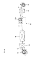
- Fig. 1 is a cross-sectional view showing a super-abrasive grain fixed type wire saw of the present invention
- Figs. 2 are schematic diagrams showing a manufacturing process of the wire saw.
- the sign 1 represents a wire saw
- the sign 10 represents a wire
- the sign 13 represents a brazing material layer
- the sign 14 represents a super-abrasive grain
- the sign 16 represents a metal plating layer.
- the wire saw 1 of the present invention includes, as shown in Fig. 1 , a wire 10 having a surface onto which super-abrasive grains 14 are dispersed and fixed.
- a brazing material layer 13 is formed on the surface of the wire 10, the super-abrasive grains 14 are temporarily fixed in a single layer onto the brazing material layer 13, and the wire is metal-plated to fix and hold the super-abrasive grains 14 onto the surface thereof.
- the metal plating layer 16 covers also the super-abrasive grains 14 because the used super-abrasive grains 14 have surfaces with conductivity.
- the present invention is not limited to the embodiment, and super-abrasive grains having surfaces without conductivity may also be used. In such a case, as shown in Figs.
- the metal plating layer 16 is grown on the brazing material layer 13 between the super-abrasive grains 14 to fill up interstices without clearance between the super-abrasive grains 14, and each super-abrasive grain 14 is enclosed. As a result, the super-abrasive grains 14 are firmly fixed.
- wire 10 various metal wires of which strength is not reduced at the melting temperature of solder can be used and a suitably used wire is composed of any of iron, nickel, cobalt, chromium, tungsten, molybdenum, copper, titanium, aluminum, and an alloy of them.
- a wire composed of high-carbon steel containing a piano wire is preferred because such a wire is inexpensively and stably available to reduce cost.
- an Sn solder, an Sn-Cu alloy solder, an Sn-Ag alloy solder, or an Sn-Sb alloy solder is preferably used.
- the reason why these solder components are preferred is as follows. That is, a metal joining material having a melting point of 450°C or less is generally referred to as a solder.
- the present invention intends to provide a wire saw that is relatively inexpensive and that includes a wire composed of high-strength high-carbon steel including a piano wire onto which super-abrasive grains are fixed. The strength of the high-carbon steel such as piano wire is reduced when the high-carbon steel is exposed to a thermal environment at more than about 300°C for a predetermined period of time or more.
- a solder to be applied to the present invention is desirably a solder having a melting point of 300°C or less and desirably 270°C or less. With the above component a solder having a melting point of 300°C or less can be designed and produced.
- the brazing material layer 13 has a thickness of 10% or less of the average grain diameter of the super-abrasive grains 14. More preferably, the thickness is 1% or more and less than 5% of the average grain diameter of the super-abrasive grains.
- the super-abrasive grains 14 to be used may be various super-abrasive grains that are conventionally used as a wire saw. In order to cut down a highly hard material such as silicon, ceramics, and sapphire, as intended by the present invention, any of diamond, CBN, and SiC or a mixture of them is preferably used because super-abrasive grains of such a substance have high hardness.
- the super-abrasive grains 14 are covered with nickel, copper, or titanium metal for good joining properties with respect to solder. Especially, super-abrasive grains coated with nickel or copper are preferred because such grains can ensure wettability to a brazing material to maintain adhesion strength.
- the metal plating layer 16 is preferably a plating composed of the same metal to the super-abrasive grains 14 or to a metal applied to the super-abrasive grains because such a metal can increase inter-adhesiveness.
- a nickel plating layer or a nickel alloy plating layer is preferably formed by electroplating.
- the manufacture of the wire saw 1 includes four major steps.
- the first step is, as shown in Fig. 2(a) , a step of forming a brazing material layer 13 on a surface of a wire 10.
- the brazing material layer 13 is formed, for example, by melting a solder in a crucible and passing a wire through the melted solder.
- Fig. 3 is a schematic view showing a manufacturing process in the first step.
- a wire 10 supplied from a wire supply reel 20 is passed through a fluxing apparatus 21 and then through a melted solder bath 22 for forming a brazing material layer (solder layer) on the surface, then is passed through a cooling zone 23 for solidifying the brazing material layer, and is taken up onto a take-up reel 24 as a precoated wire 11.
- Examples of the fluxing apparatus 21 include an apparatus employing a method of spraying a flux from a nozzle and an apparatus employing a method of passing a wire through a flux storage bath.
- the melted solder bath 22 is equipped with a heater that can thoroughly melt a solder.
- the melted solder bath is also equipped with a guiding apparatus so as to pass a wire through the melted solder bath and thus the wire 10 is passed through the melted solder.
- the brazing material layer 13 (solder layer) is formed.
- the cooling zone 23 is provided before the wire is taken up onto the take-up reel 24.
- Fig. 2(a) shows a cross-sectional view of the manufactured wire after the first step and shows a state of the wire 10 having a surface on which the brazing material layer 13 is formed.
- the wire is referred to as a precoated wire 11.
- the thickness of the brazing material layer 13 (solder layer) formed in the first step varies depending on the viscosity and surface tension of a melted solder and the running speed of a wire.
- the thickness is preferably 10% or less of the average grain diameter of the super-abrasive grains 14 and more preferably 1% or more and less than 5%.
- the thickness is preferably 2 ⁇ m or less for super-abrasive grains having an average grain diameter of 40 to 60 ⁇ m and is preferably 1 ⁇ m or less for super-abrasive grains having an average grain diameter of 10 to 20 ⁇ m.
- the embodiment employs hot-dip plating, but the metal plating layer, of course, can be formed, for example, by electroplating of tin.
- super-abrasive grains 14 are dispersed and adhered in a single layer onto the brazing material layer 13 formed in the first step.
- the surface of the precoated wire 11 manufactured in the first step is wetted with a liquid that is decomposed or evaporated at the melting temperature of a solder or less.
- the wetted wire is passed through a container containing super-abrasive grains and the super-abrasive grains are adhered onto the wire surface due to the wet.
- it is actually observed that super-abrasive grains are present on other super-abrasive grains due to inter-cohesive power of the super-abrasive grains, which is not shown in Fig. 2(b) .
- the surface of the precoated wire 11 that is supplied from a supply reel 30 is wetted with a liquid coating apparatus 31. Then, the precoated wire 11 having the wetted surface is passed through a super-abrasive grain dispersion apparatus 32a in a super-abrasive grain adherence zone 32, and super-abrasive grains 14 are adhered onto the surface.
- These processes are the second step. Consequently, as shown in Fig. 2(b) , a liquid layer 15 is formed on the surface of the brazing material layer 13 of the precoated wire 11, and the super-abrasive grains 14 are adhered onto the surface of the precoated wire 11 due to the wet of liquid.
- the step is preferably equipped with a function of controlling the adhesion density of super-abrasive grains by the control of the wire running speed or the like.
- the second step can be performed by passing the precoated wire having a surface that is similarly wetted through a storage bath of a super-abrasive grain powder or by adhering super-abrasive grains onto the precoated wire using the principle of electrostatic coating.
- the adhesion can be also achieved by simple van der Waals force or by static electrification.
- Each method is also characterized by the control of the adhesion amount of super-abrasive grains by the control of wire running speed or the amount of spray.
- the brazing material layer 13 on the wire onto which the super-abrasive grains 14 are temporarily fixed in the second step is heated and melted, and then the brazing material layer is cooled and solidified to adhere the super-abrasive grains 14 onto the surface of the brazing material layer 13 for temporary adhesion (temporary fixing).
- the step is performed subsequent to the second step, as shown in the schematic view in Fig. 4 .
- the super-abrasive-grains-adhered precoated wire that is passed through the super-abrasive grain dispersion apparatus 32 is guided into a furnace 33 to be heated.
- the furnace 33 can heat to a temperature sufficient to melt the brazing material layer 13 of the precoated wire.
- Fig. 2(c) shows the cross section of the wire after the step, showing the state in which the melted solder in the brazing material layer 13 is drawn to the periphery of the super-abrasive grains 14 due to surface tension and then solidified to form fillets 13a. That is, the advantage of the method is that the fillets 13a are formed around the adhesion face of the super-abrasive grains 14 and thus the super-abrasive grains 14 are stably joined.
- the presence of the fillets 13a leads to smooth metal plating around the super-abrasive grains 14 in the following step and hence can provide a wire saw having high abrasive grain holding power unlike the joining state of super-abrasive grains by the electrodeposition by which no fillet 13a is formed.
- the super-abrasive grains that are excessively adhered onto the super-abrasive grains 14 due to the inter-cohesive power of the super-abrasive grains in the second step are not in contact with the brazing material layer 13. Hence, these grains are not joined to the wire in the third step and are removed, for example, by air flow in the cooling zone 34. Accordingly, the super-abrasive grains 14 on the wire form a single layer.
- the wire manufactured in the third step is referred to as a super-abrasive-grains-temporarily-adhered wire 12.
- the adhesive strength of the super-abrasive grains to the wire depends on the adhesive strengths between a solder in the brazing material layer 13 and the super-abrasive grains and between the solder and the wire.
- the adhesive strength is insufficient since nearly one face alone on the super-abrasive grain is adhered, and such a wire in the state cannot be used as a wire saw. Therefore, when such a wire is used as the wire saw, the super-abrasive grains are required to be more firmly fixed onto the wire in the fourth step described below.
- the super-abrasive-grains-temporarily-adhered wire 12 is metal-plated to firmly fix the super-abrasive grains 14 onto the wire.
- Fig. 5 is a schematic view showing a manufacturing process of the fourth step.
- the super-abrasive-grains-temporarily-adhered wire 12 that is manufactured in the third step is supplied from a supply reel 40, is passed through a defatting bath 42, an acid washing bath 43, a water washing bath 44, a plating bath 45, and a water washing bath 46, and is taken up onto a take-up reel 47.
- the plating bath 45 is equipped with an anode 45c and a load-dispatching roll 45b to make the wire a cathode and with a direct-current power source 45a.
- a metal plating layer is formed on the surface of the super-abrasive-grains-temporarily-adhered wire 12.
- the metal plating layer is formed not only on the brazing material layer on the wire but also on the super-abrasive grains, and hence the super-abrasive grains are very firmly fixed onto the wire.
- the super-abrasive grain-fixed wire having the cross sections in Fig. 2(d) and Fig. 1 can be obtained.
- the thickness of the metal plating can be controlled by wire running speed and plating current.
- the metal plating also covers the surface of the super-abrasive grains 14 in the case of the super-abrasive grains 14 coated with a conductive material as in the embodiment.
- the thickness is preferably 3 to 10 ⁇ m and more preferably 3 to 5 ⁇ m.
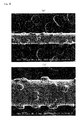
- the wire saw of Example 1 was manufactured by using the processes in Figs. 3 to 5 described above.
- a brass plated piano wire having a diameter of 180 ⁇ m was used as the wire and a solder plating layer having a thickness of 2 to 2.5 ⁇ m was formed using an Sn-Ag alloy solder having a melting temperature of 220°C to prepare a precoated wire.
- the precoated wire was wetted with a liquid, then nickel coated diamond abrasive grains having a size of 30 to 40 ⁇ m were dispersed and adhered at a wire running speed of 20 m/minute, and the solder was melted and solidified to prepare a super-abrasive-grains-temporarily-adhered wire.
- FIG. 7(a) is a magnified photograph of the super-abrasive-grains-temporarily-adhered wire.
- the solder was drawn to the periphery of the super-abrasive grains to form fillets.
- the thickness of the solder plating layer around the wire seems to be on the submicron-level.
- the super-abrasive-grains-temporarily-adhered wire was nickel plated at a wire running speed of 10 m/minute and a current of 20 A until the thickness reached 10 ⁇ m.
- Fig. 7(b) is a magnified photograph of the completed wire saw after the metal plating. It can be seen that the metal plating layer also covers the fillets and the super-abrasive grains are fixed with the grains completely covered.
- the diamond abrasive grains were fixed onto the wire by the electrodeposition.
- the wire had a diameter of 180 micron
- the super-abrasive grains were diamond abrasive grains (an average grain diameter of 30 to 40 micron)
- the electrodeposition material was nickel.
- Fig. 7(c) is a magnified photograph of the wire saw of Comparative Example 1.
- a black shadow may appear around the adhesion surface of the super-abrasive grains coated with the metal plating. This shows that the metal plating was not thoroughly adhered to interstices around the adhesion surface and the metal plating on the wire surface and the metal plating on the super-abrasive grain surface were not thoroughly bonded because there was no fillet of a solder plating layer as a primary coating of the metal plating as in Example 1.
- Example 2 two types of wire saws (Example 2 and Example 3) were manufactured and the results of processing test will be described.
- Fig. 8(a) is a photograph of the wire saw of Example 2 before processing and Fig. 8(b) is a magnified photograph of the wire saw.
- Fig. 9(a) is a photograph of the wire saw of Example 3 before processing and Fig. 9(b) is a magnified photograph of the wire saw.
- the wire saw including the brazing material layer having a small thickness of about 2% as in Example 2 led to small R on the metal plating surface on the bottom of a diamond grain as shown in Fig. 8 .
- the wire saw including the brazing material layer having a thickness of about 5% as in Example 3 led to larger R than that of the wire saw of Example 2 as shown in Fig. 9 .
- a brazing material layer having a larger thickness leads to a larger fillet that is formed by temporarily fixing a diamond grain onto the brazing material layer and R on the surface of metal plating deposited on the diamond-grains-temporarily-fixed wire is accordingly increased by the fillet.
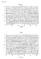
- Example 2 Using each wire saw of Example 2 and Example 3, a sapphire ingot having a length of 49 mm was subjected to slice processing at a wire running speed (linear velocity) of 500 m/min to prepare a wafer.
- the measurement was carried out using a surface roughness analyzer "SURFCOM-1500-SD3" manufactured by TOKYO SEIMITSU CO., LTD.
- Fig. 10 and Fig. 11 show graphs of the results (warpage and TTV) of the processing test by the wire saws of Example 2 and Example 3, respectively.
- Thirty-four pieces of wafers manufactured by the slice processing using the wire saw of Example 2 gave a very small warpage mean value of 8.178 ⁇ m.
- the wire saw achieved small variations in the value and stable processing.
- TTV is a variation amount ( ⁇ m) in the thickness of one wafer and was determined as the difference between a maximum value and a minimum value among thicknesses at three points.
- the mean value of TTV was as small as 9.529 ⁇ m, which shows that the processing achieved uniform thickness.
- Example 3 Fifty pieces of wafers manufactured using the wire saw of Example 3 gave a warpage mean value of 12.099 ⁇ m.
- the processing accuracy was inferior to Example 2, but the wire saw achieved excellent processing accuracy.
- the reason why Example 3 was inferior to Example 2 is supposed that the metal plating surface on the bottom of a diamond grain had relatively large R, the diamond grains did not fall, the cutting chip discharge deteriorated, the wire thickness was not largely reduced, the cutting quality deteriorated, and thus the warpage was increased.
- the mean value of TTV was as small as 9.020 ⁇ m, which shows that the processing achieved uniform thickness.
Landscapes
- Engineering & Computer Science (AREA)
- Mechanical Engineering (AREA)
- Mining & Mineral Resources (AREA)
- Physics & Mathematics (AREA)
- Condensed Matter Physics & Semiconductors (AREA)
- General Physics & Mathematics (AREA)
- Manufacturing & Machinery (AREA)
- Computer Hardware Design (AREA)
- Microelectronics & Electronic Packaging (AREA)
- Power Engineering (AREA)
- Polishing Bodies And Polishing Tools (AREA)
Applications Claiming Priority (3)
| Application Number | Priority Date | Filing Date | Title |
|---|---|---|---|
| JP2009254310A JP5515646B2 (ja) | 2009-11-05 | 2009-11-05 | ワイヤソー及びワイヤソーの製造方法 |
| JP2010226829A JP2012081525A (ja) | 2010-10-06 | 2010-10-06 | 超砥粒固定式ワイヤソー |
| PCT/JP2010/069294 WO2011055692A1 (fr) | 2009-11-05 | 2010-10-29 | Scie à fil de type fixe à grains super-abrasifs, et procédé de fabrication de scie à fil de type fixe à grains super-abrasifs |
Publications (1)
| Publication Number | Publication Date |
|---|---|
| EP2497602A1 true EP2497602A1 (fr) | 2012-09-12 |
Family
ID=43969932
Family Applications (1)
| Application Number | Title | Priority Date | Filing Date |
|---|---|---|---|
| EP10828252A Withdrawn EP2497602A1 (fr) | 2009-11-05 | 2010-10-29 | Scie à fil de type fixe à grains super-abrasifs, et procédé de fabrication de scie à fil de type fixe à grains super-abrasifs |
Country Status (5)
| Country | Link |
|---|---|
| US (1) | US20130032129A1 (fr) |
| EP (1) | EP2497602A1 (fr) |
| KR (1) | KR20120102679A (fr) |
| CN (1) | CN102770240A (fr) |
| WO (1) | WO2011055692A1 (fr) |
Cited By (11)
| Publication number | Priority date | Publication date | Assignee | Title |
|---|---|---|---|---|
| US9028948B2 (en) | 2009-08-14 | 2015-05-12 | Saint-Gobain Abrasives, Inc. | Abrasive articles including abrasive particles bonded to an elongated body, and methods of forming thereof |
| US9067268B2 (en) | 2009-08-14 | 2015-06-30 | Saint-Gobain Abrasives, Inc. | Abrasive articles including abrasive particles bonded to an elongated body |
| US9186816B2 (en) | 2010-12-30 | 2015-11-17 | Saint-Gobain Abrasives, Inc. | Abrasive article and method of forming |
| US9211634B2 (en) | 2011-09-29 | 2015-12-15 | Saint-Gobain Abrasives, Inc. | Abrasive articles including abrasive particles bonded to an elongated substrate body having a barrier layer, and methods of forming thereof |
| US9254552B2 (en) | 2012-06-29 | 2016-02-09 | Saint-Gobain Abrasives, Inc. | Abrasive article and method of forming |
| US9278429B2 (en) | 2012-06-29 | 2016-03-08 | Saint-Gobain Abrasives, Inc. | Abrasive article for abrading and sawing through workpieces and method of forming |
| US9375826B2 (en) | 2011-09-16 | 2016-06-28 | Saint-Gobain Abrasives, Inc. | Abrasive article and method of forming |
| US9409243B2 (en) | 2013-04-19 | 2016-08-09 | Saint-Gobain Abrasives, Inc. | Abrasive article and method of forming |
| US9533397B2 (en) | 2012-06-29 | 2017-01-03 | Saint-Gobain Abrasives, Inc. | Abrasive article and method of forming |
| US9902044B2 (en) | 2012-06-29 | 2018-02-27 | Saint-Gobain Abrasives, Inc. | Abrasive article and method of forming |
| US10119368B2 (en) | 2013-07-05 | 2018-11-06 | Bruce A. Tunget | Apparatus and method for cultivating a downhole surface |
Families Citing this family (11)
| Publication number | Priority date | Publication date | Assignee | Title |
|---|---|---|---|---|
| US8291895B2 (en) * | 2007-09-05 | 2012-10-23 | University Of South Carolina | Methods, wires, and apparatus for slicing hard materials |
| TWI461249B (zh) * | 2010-04-27 | 2014-11-21 | Kinik Co | 線鋸及其製作方法 |
| JP6119495B2 (ja) * | 2013-08-05 | 2017-04-26 | 新日鐵住金株式会社 | ソーワイヤ及びコアワイヤ |
| CN107427943B (zh) | 2015-03-13 | 2019-07-05 | 江阴贝卡尔特合金材料有限公司 | 具有金属合金固定层的固结研磨锯丝的制造方法和所制造的锯丝 |
| TWI621505B (zh) * | 2015-06-29 | 2018-04-21 | 聖高拜磨料有限公司 | 研磨物品及形成方法 |
| GB2540385B (en) * | 2015-07-15 | 2017-10-11 | C4 Carbides Ltd | Improvements in or relating to tool blades and their manufacture |
| JP7113365B2 (ja) * | 2017-05-10 | 2022-08-05 | パナソニックIpマネジメント株式会社 | ソーワイヤー及び切断装置 |
| JP7241294B2 (ja) * | 2017-05-10 | 2023-03-17 | パナソニックIpマネジメント株式会社 | ソーワイヤー及び切断装置 |
| US11358232B2 (en) * | 2017-10-16 | 2022-06-14 | Stewart-Macdonald Manufacturing Company | Rounded nut files for stringed instruments |
| JP2021003806A (ja) * | 2018-01-29 | 2021-01-14 | スリーエム イノベイティブ プロパティズ カンパニー | 糸状部材への印刷方法、及び糸状のこぎり |
| CN116900406B (zh) * | 2023-09-12 | 2023-12-05 | 江苏聚成金刚石科技股份有限公司 | 一种超细直径金刚石线锯及其制备方法 |
Family Cites Families (14)
| Publication number | Priority date | Publication date | Assignee | Title |
|---|---|---|---|---|
| JPS5857558A (ja) | 1981-09-30 | 1983-04-05 | Aisin Warner Ltd | 車両用無段変速装置 |
| JPH0379264A (ja) * | 1989-08-18 | 1991-04-04 | Tone Boring Co | カツティングワイヤー工具 |
| JPH10118938A (ja) * | 1996-10-17 | 1998-05-12 | Osaka Diamond Ind Co Ltd | 超砥粒砥石 |
| TW394723B (en) * | 1997-04-04 | 2000-06-21 | Sung Chien Min | Abrasive tools with patterned grit distribution and method of manufacture |
| US6065462A (en) * | 1997-11-28 | 2000-05-23 | Laser Technology West Limited | Continuous wire saw loop and method of manufacture thereof |
| CN1238253A (zh) * | 1998-06-04 | 1999-12-15 | 林心正 | 具不连续切割面的线锯 |
| DE10022994A1 (de) * | 2000-05-11 | 2001-12-20 | Wacker Chemie Gmbh | Nickel-Diamant beschichteter Sägedraht mit verbesserter Verankerung der Diamantpartikel |
| JP2002205272A (ja) | 2001-01-09 | 2002-07-23 | Asahi Diamond Industrial Co Ltd | 超砥粒工具及びその製造方法 |
| JP2004174680A (ja) * | 2002-11-28 | 2004-06-24 | Kanai Hiroaki | 固定砥粒式ソーワイヤ及び砥粒固着方法 |
| JP2006123024A (ja) * | 2004-10-26 | 2006-05-18 | Nakamura Choko:Kk | 固定砥粒式ワイヤーソーとその製造方法 |
| JP4703448B2 (ja) | 2006-03-22 | 2011-06-15 | 株式会社ノリタケスーパーアブレーシブ | レジンボンドワイヤソー |
| JP2008221406A (ja) | 2007-03-13 | 2008-09-25 | Nakamura Choko:Kk | 固定砥粒式ワイヤーソー及びその製造方法 |
| CN102712080B (zh) * | 2010-06-15 | 2014-03-05 | 新日铁住金株式会社 | 锯线 |
| TWI466990B (zh) * | 2010-12-30 | 2015-01-01 | Saint Gobain Abrasives Inc | 磨料物品及形成方法 |
-
2010
- 2010-10-29 EP EP10828252A patent/EP2497602A1/fr not_active Withdrawn
- 2010-10-29 CN CN2010800503570A patent/CN102770240A/zh active Pending
- 2010-10-29 WO PCT/JP2010/069294 patent/WO2011055692A1/fr active Application Filing
- 2010-10-29 US US13/505,810 patent/US20130032129A1/en not_active Abandoned
- 2010-10-29 KR KR1020127014451A patent/KR20120102679A/ko not_active Application Discontinuation
Non-Patent Citations (1)
| Title |
|---|
| See references of WO2011055692A1 * |
Cited By (13)
| Publication number | Priority date | Publication date | Assignee | Title |
|---|---|---|---|---|
| US9028948B2 (en) | 2009-08-14 | 2015-05-12 | Saint-Gobain Abrasives, Inc. | Abrasive articles including abrasive particles bonded to an elongated body, and methods of forming thereof |
| US9067268B2 (en) | 2009-08-14 | 2015-06-30 | Saint-Gobain Abrasives, Inc. | Abrasive articles including abrasive particles bonded to an elongated body |
| US9186816B2 (en) | 2010-12-30 | 2015-11-17 | Saint-Gobain Abrasives, Inc. | Abrasive article and method of forming |
| US9248583B2 (en) | 2010-12-30 | 2016-02-02 | Saint-Gobain Abrasives, Inc. | Abrasive article and method of forming |
| US9375826B2 (en) | 2011-09-16 | 2016-06-28 | Saint-Gobain Abrasives, Inc. | Abrasive article and method of forming |
| US9211634B2 (en) | 2011-09-29 | 2015-12-15 | Saint-Gobain Abrasives, Inc. | Abrasive articles including abrasive particles bonded to an elongated substrate body having a barrier layer, and methods of forming thereof |
| US9278429B2 (en) | 2012-06-29 | 2016-03-08 | Saint-Gobain Abrasives, Inc. | Abrasive article for abrading and sawing through workpieces and method of forming |
| US9254552B2 (en) | 2012-06-29 | 2016-02-09 | Saint-Gobain Abrasives, Inc. | Abrasive article and method of forming |
| US9533397B2 (en) | 2012-06-29 | 2017-01-03 | Saint-Gobain Abrasives, Inc. | Abrasive article and method of forming |
| US9902044B2 (en) | 2012-06-29 | 2018-02-27 | Saint-Gobain Abrasives, Inc. | Abrasive article and method of forming |
| US9409243B2 (en) | 2013-04-19 | 2016-08-09 | Saint-Gobain Abrasives, Inc. | Abrasive article and method of forming |
| EP2986416A4 (fr) * | 2013-04-19 | 2016-11-23 | Saint Gobain Abrasives Inc | Article abrasif et procédé de fabrication |
| US10119368B2 (en) | 2013-07-05 | 2018-11-06 | Bruce A. Tunget | Apparatus and method for cultivating a downhole surface |
Also Published As
| Publication number | Publication date |
|---|---|
| CN102770240A (zh) | 2012-11-07 |
| US20130032129A1 (en) | 2013-02-07 |
| KR20120102679A (ko) | 2012-09-18 |
| WO2011055692A1 (fr) | 2011-05-12 |
Similar Documents
| Publication | Publication Date | Title |
|---|---|---|
| EP2497602A1 (fr) | Scie à fil de type fixe à grains super-abrasifs, et procédé de fabrication de scie à fil de type fixe à grains super-abrasifs | |
| KR101509852B1 (ko) | 쏘 와이어 및 쏘 와이어의 제조 방법 | |
| US10596681B2 (en) | Abrasive article and method of forming | |
| JP5515646B2 (ja) | ワイヤソー及びワイヤソーの製造方法 | |
| JP6564474B2 (ja) | 砥粒品および形成方法 | |
| US9533397B2 (en) | Abrasive article and method of forming | |
| TWI466990B (zh) | 磨料物品及形成方法 | |
| JP2007152485A (ja) | ソーワイヤの製造方法 | |
| JP4427531B2 (ja) | ワイヤーソーの断線検出方法および品質検査方法ならびに切断物の製造方法 | |
| US9278429B2 (en) | Abrasive article for abrading and sawing through workpieces and method of forming | |
| US20140311472A1 (en) | Abrasive Article and Method of Forming | |
| CN101596749B (zh) | 钎焊钻石线锯的制作方法 | |
| JP5789077B2 (ja) | 固定砥粒式ワイヤーソー及びその製造方法 | |
| CN103857494A (zh) | 研磨制品和形成方法 | |
| WO2013179434A1 (fr) | Scie à fil à grains abrasifs fixes, son procédé de fabrication et procédé de découpe de pièce à l'aide de celle-ci | |
| JP2004174680A (ja) | 固定砥粒式ソーワイヤ及び砥粒固着方法 | |
| JP2006123024A (ja) | 固定砥粒式ワイヤーソーとその製造方法 | |
| JP2012081525A (ja) | 超砥粒固定式ワイヤソー | |
| JP2013144352A (ja) | ソーワイヤの製造方法及びその製造装置 | |
| JP2012213843A (ja) | ダイヤモンドソーワイヤの製造方法及びその製造装置 | |
| JPH06320428A (ja) | メタルボンド砥石の製造方法 | |
| WO2014118003A1 (fr) | Fil de sciage abrasif fixe comprenant des interfaces d'oxyde de nickel entre des sous-couches de nickel | |
| TW201311413A (zh) | 具有硬質薄膜之固定磨粒電鍍切割線 |
Legal Events
| Date | Code | Title | Description |
|---|---|---|---|
| PUAI | Public reference made under article 153(3) epc to a published international application that has entered the european phase |
Free format text: ORIGINAL CODE: 0009012 |
|
| 17P | Request for examination filed |
Effective date: 20120522 |
|
| AK | Designated contracting states |
Kind code of ref document: A1 Designated state(s): AL AT BE BG CH CY CZ DE DK EE ES FI FR GB GR HR HU IE IS IT LI LT LU LV MC MK MT NL NO PL PT RO RS SE SI SK SM TR |
|
| DAX | Request for extension of the european patent (deleted) | ||
| STAA | Information on the status of an ep patent application or granted ep patent |
Free format text: STATUS: THE APPLICATION HAS BEEN WITHDRAWN |
|
| 18W | Application withdrawn |
Effective date: 20150828 |