EP2496949B1 - Ventileinheit, mikrofluidische vorrichtung damit sowie antriebsverfahren für die ventileinheit - Google Patents
Ventileinheit, mikrofluidische vorrichtung damit sowie antriebsverfahren für die ventileinheit Download PDFInfo
- Publication number
- EP2496949B1 EP2496949B1 EP10828477.9A EP10828477A EP2496949B1 EP 2496949 B1 EP2496949 B1 EP 2496949B1 EP 10828477 A EP10828477 A EP 10828477A EP 2496949 B1 EP2496949 B1 EP 2496949B1
- Authority
- EP
- European Patent Office
- Prior art keywords
- channel
- valve
- micro
- valve unit
- unit according
- Prior art date
- Legal status (The legal status is an assumption and is not a legal conclusion. Google has not performed a legal analysis and makes no representation as to the accuracy of the status listed.)
- Not-in-force
Links
Images


Classifications
-
- B—PERFORMING OPERATIONS; TRANSPORTING
- B01—PHYSICAL OR CHEMICAL PROCESSES OR APPARATUS IN GENERAL
- B01L—CHEMICAL OR PHYSICAL LABORATORY APPARATUS FOR GENERAL USE
- B01L3/00—Containers or dishes for laboratory use, e.g. laboratory glassware; Droppers
- B01L3/50—Containers for the purpose of retaining a material to be analysed, e.g. test tubes
- B01L3/502—Containers for the purpose of retaining a material to be analysed, e.g. test tubes with fluid transport, e.g. in multi-compartment structures
- B01L3/5027—Containers for the purpose of retaining a material to be analysed, e.g. test tubes with fluid transport, e.g. in multi-compartment structures by integrated microfluidic structures, i.e. dimensions of channels and chambers are such that surface tension forces are important, e.g. lab-on-a-chip
- B01L3/502738—Containers for the purpose of retaining a material to be analysed, e.g. test tubes with fluid transport, e.g. in multi-compartment structures by integrated microfluidic structures, i.e. dimensions of channels and chambers are such that surface tension forces are important, e.g. lab-on-a-chip characterised by integrated valves
-
- G—PHYSICS
- G01—MEASURING; TESTING
- G01N—INVESTIGATING OR ANALYSING MATERIALS BY DETERMINING THEIR CHEMICAL OR PHYSICAL PROPERTIES
- G01N35/00—Automatic analysis not limited to methods or materials provided for in any single one of groups G01N1/00 - G01N33/00; Handling materials therefor
- G01N35/08—Automatic analysis not limited to methods or materials provided for in any single one of groups G01N1/00 - G01N33/00; Handling materials therefor using a stream of discrete samples flowing along a tube system, e.g. flow injection analysis
-
- F—MECHANICAL ENGINEERING; LIGHTING; HEATING; WEAPONS; BLASTING
- F16—ENGINEERING ELEMENTS AND UNITS; GENERAL MEASURES FOR PRODUCING AND MAINTAINING EFFECTIVE FUNCTIONING OF MACHINES OR INSTALLATIONS; THERMAL INSULATION IN GENERAL
- F16K—VALVES; TAPS; COCKS; ACTUATING-FLOATS; DEVICES FOR VENTING OR AERATING
- F16K99/00—Subject matter not provided for in other groups of this subclass
- F16K99/0001—Microvalves
- F16K99/0003—Constructional types of microvalves; Details of the cutting-off member
- F16K99/0032—Constructional types of microvalves; Details of the cutting-off member using phase transition or influencing viscosity
-
- F—MECHANICAL ENGINEERING; LIGHTING; HEATING; WEAPONS; BLASTING
- F16—ENGINEERING ELEMENTS AND UNITS; GENERAL MEASURES FOR PRODUCING AND MAINTAINING EFFECTIVE FUNCTIONING OF MACHINES OR INSTALLATIONS; THERMAL INSULATION IN GENERAL
- F16K—VALVES; TAPS; COCKS; ACTUATING-FLOATS; DEVICES FOR VENTING OR AERATING
- F16K99/00—Subject matter not provided for in other groups of this subclass
- F16K99/0001—Microvalves
- F16K99/0034—Operating means specially adapted for microvalves
- F16K99/0042—Electric operating means therefor
- F16K99/0044—Electric operating means therefor using thermo-electric means
-
- G—PHYSICS
- G01—MEASURING; TESTING
- G01N—INVESTIGATING OR ANALYSING MATERIALS BY DETERMINING THEIR CHEMICAL OR PHYSICAL PROPERTIES
- G01N37/00—Details not covered by any other group of this subclass
-
- B—PERFORMING OPERATIONS; TRANSPORTING
- B01—PHYSICAL OR CHEMICAL PROCESSES OR APPARATUS IN GENERAL
- B01L—CHEMICAL OR PHYSICAL LABORATORY APPARATUS FOR GENERAL USE
- B01L2300/00—Additional constructional details
- B01L2300/08—Geometry, shape and general structure
- B01L2300/0803—Disc shape
-
- B—PERFORMING OPERATIONS; TRANSPORTING
- B01—PHYSICAL OR CHEMICAL PROCESSES OR APPARATUS IN GENERAL
- B01L—CHEMICAL OR PHYSICAL LABORATORY APPARATUS FOR GENERAL USE
- B01L2300/00—Additional constructional details
- B01L2300/18—Means for temperature control
- B01L2300/1861—Means for temperature control using radiation
-
- B—PERFORMING OPERATIONS; TRANSPORTING
- B01—PHYSICAL OR CHEMICAL PROCESSES OR APPARATUS IN GENERAL
- B01L—CHEMICAL OR PHYSICAL LABORATORY APPARATUS FOR GENERAL USE
- B01L2400/00—Moving or stopping fluids
- B01L2400/04—Moving fluids with specific forces or mechanical means
- B01L2400/0403—Moving fluids with specific forces or mechanical means specific forces
- B01L2400/0406—Moving fluids with specific forces or mechanical means specific forces capillary forces
-
- B—PERFORMING OPERATIONS; TRANSPORTING
- B01—PHYSICAL OR CHEMICAL PROCESSES OR APPARATUS IN GENERAL
- B01L—CHEMICAL OR PHYSICAL LABORATORY APPARATUS FOR GENERAL USE
- B01L2400/00—Moving or stopping fluids
- B01L2400/04—Moving fluids with specific forces or mechanical means
- B01L2400/0403—Moving fluids with specific forces or mechanical means specific forces
- B01L2400/0409—Moving fluids with specific forces or mechanical means specific forces centrifugal forces
-
- B—PERFORMING OPERATIONS; TRANSPORTING
- B01—PHYSICAL OR CHEMICAL PROCESSES OR APPARATUS IN GENERAL
- B01L—CHEMICAL OR PHYSICAL LABORATORY APPARATUS FOR GENERAL USE
- B01L2400/00—Moving or stopping fluids
- B01L2400/06—Valves, specific forms thereof
- B01L2400/0677—Valves, specific forms thereof phase change valves; Meltable, freezing, dissolvable plugs; Destructible barriers
-
- C—CHEMISTRY; METALLURGY
- C08—ORGANIC MACROMOLECULAR COMPOUNDS; THEIR PREPARATION OR CHEMICAL WORKING-UP; COMPOSITIONS BASED THEREON
- C08L—COMPOSITIONS OF MACROMOLECULAR COMPOUNDS
- C08L2201/00—Properties
- C08L2201/12—Shape memory
-
- F—MECHANICAL ENGINEERING; LIGHTING; HEATING; WEAPONS; BLASTING
- F16—ENGINEERING ELEMENTS AND UNITS; GENERAL MEASURES FOR PRODUCING AND MAINTAINING EFFECTIVE FUNCTIONING OF MACHINES OR INSTALLATIONS; THERMAL INSULATION IN GENERAL
- F16K—VALVES; TAPS; COCKS; ACTUATING-FLOATS; DEVICES FOR VENTING OR AERATING
- F16K99/00—Subject matter not provided for in other groups of this subclass
- F16K2099/0082—Microvalves adapted for a particular use
- F16K2099/0084—Chemistry or biology, e.g. "lab-on-a-chip" technology
-
- Y—GENERAL TAGGING OF NEW TECHNOLOGICAL DEVELOPMENTS; GENERAL TAGGING OF CROSS-SECTIONAL TECHNOLOGIES SPANNING OVER SEVERAL SECTIONS OF THE IPC; TECHNICAL SUBJECTS COVERED BY FORMER USPC CROSS-REFERENCE ART COLLECTIONS [XRACs] AND DIGESTS
- Y10—TECHNICAL SUBJECTS COVERED BY FORMER USPC
- Y10T—TECHNICAL SUBJECTS COVERED BY FORMER US CLASSIFICATION
- Y10T137/00—Fluid handling
- Y10T137/0318—Processes
- Y10T137/0391—Affecting flow by the addition of material or energy
-
- Y—GENERAL TAGGING OF NEW TECHNOLOGICAL DEVELOPMENTS; GENERAL TAGGING OF CROSS-SECTIONAL TECHNOLOGIES SPANNING OVER SEVERAL SECTIONS OF THE IPC; TECHNICAL SUBJECTS COVERED BY FORMER USPC CROSS-REFERENCE ART COLLECTIONS [XRACs] AND DIGESTS
- Y10—TECHNICAL SUBJECTS COVERED BY FORMER USPC
- Y10T—TECHNICAL SUBJECTS COVERED BY FORMER US CLASSIFICATION
- Y10T137/00—Fluid handling
- Y10T137/1624—Destructible or deformable element controlled
- Y10T137/1797—Heat destructible or fusible
- Y10T137/1812—In fluid flow path
-
- Y—GENERAL TAGGING OF NEW TECHNOLOGICAL DEVELOPMENTS; GENERAL TAGGING OF CROSS-SECTIONAL TECHNOLOGIES SPANNING OVER SEVERAL SECTIONS OF THE IPC; TECHNICAL SUBJECTS COVERED BY FORMER USPC CROSS-REFERENCE ART COLLECTIONS [XRACs] AND DIGESTS
- Y10—TECHNICAL SUBJECTS COVERED BY FORMER USPC
- Y10T—TECHNICAL SUBJECTS COVERED BY FORMER US CLASSIFICATION
- Y10T137/00—Fluid handling
- Y10T137/206—Flow affected by fluid contact, energy field or coanda effect [e.g., pure fluid device or system]
- Y10T137/218—Means to regulate or vary operation of device
- Y10T137/2191—By non-fluid energy field affecting input [e.g., transducer]
- Y10T137/2196—Acoustical or thermal energy
-
- Y—GENERAL TAGGING OF NEW TECHNOLOGICAL DEVELOPMENTS; GENERAL TAGGING OF CROSS-SECTIONAL TECHNOLOGIES SPANNING OVER SEVERAL SECTIONS OF THE IPC; TECHNICAL SUBJECTS COVERED BY FORMER USPC CROSS-REFERENCE ART COLLECTIONS [XRACs] AND DIGESTS
- Y10—TECHNICAL SUBJECTS COVERED BY FORMER USPC
- Y10T—TECHNICAL SUBJECTS COVERED BY FORMER US CLASSIFICATION
- Y10T137/00—Fluid handling
- Y10T137/4456—With liquid valves or liquid trap seals
- Y10T137/4643—Liquid valves
Definitions
- Apparatuses and methods consistent with exemplary embodiments relate to a valve unit, a microfluidic device having the same and a method for driving the valve unit and, more particularly, to a valve unit for control of a micro fluid flow, a microfluidic device equipped with the same and a method of driving the valve unit for control of a fluid flow.
- a microfluidic device is utilized to conduct biological or chemical reactions by operating upon a small amount of fluid.
- the microfluidic device has a microfluidic structure provided in a platform in different forms or shapes such as a chip, a disk, etc.
- the microfluidic structure typically has a chamber to receive a fluid therein, a channel through which the fluid passes or flows and a valve to control the fluid flow, wherein the chamber, channel and valve are combined and arranged according to different assembly designs.
- a known device is disclosed in document EP2026074 A2 .
- a microfluidic structure is arranged on a chip type platform what is referred to as a 'bio-chip.
- a device fabricated for multi-stage treatment and/or operation on a single chip is referred to as a 'lab-on-a chip'.
- a driving pressure In order to flow and transport a fluid in a microfluidic structure of a microfluidic device, a driving pressure is generally required.
- the driving pressure may be capillary pressure or pressure generated using an alternative pump may be used.
- a centrifugal microfluidic device having a microfluidic structure mounted on a disk type platform, capable of conducting a series of operations while shifting a fluid by centrifugal force has been proposed.
- the microfluidic device is often referred as a lab compact disk (CD) or a lab-on-a CD.
- the valve of the microfluidic device may be operated in a magnetic control manner or using a phase transition material, so as to open and close a channel.
- a normally open valve is operated by installing a chamber to receive the phase transition material close to a channel and heating the phase transition material to flow into the channel, in turn closing the channel.
- a microfluidic device using centrifugal force to transport a fluid has a disadvantage in that a channel may not be completely closed using a phase transition material.
- phase transition material generally has poor heat tolerance and entails a problem in that the phase transition material closing a channel is fused in a high temperature environment, in turn opening the channel even in the case where the channel must be closed.
- Exemplary embodiments provide a normally open valve unit to permanently close a channel during driving of a valve, a microfluidic device equipped with the valve unit, and a method of driving the valve unit are provided.
- Exemplary embodiments also provide a valve unit to continuously close a channel independent of temperature during driving of a valve, a microfluidic device equipped with the valve unit, and a method of driving the valve unit are provided.
- a valve unit which opens and closes a channel
- the valve unit including: a valve substance containing a phase transition material; a valve substance chamber which communicates with the channel and receives the valve substance; a micro-channel part provided in the channel; and a fusion structure formed in the micro-channel part, wherein the valve substance contained in the valve substance chamber is fused by applied energy and flows into the micro-channel part, and the valve substance in the micro-channel part is heated to melt the fusion structure and conduct fused bonding of the channel, in turn closing the channel.
- the valve unit may be included in a rotational disk type microfluidic device and the microfluidic device may typically include a first plate and a second plate combined with the first plate in order to isolate the valve substance chamber from the channel.
- the valve unit may further include a guidance channel to guide the fused valve substance to the micro-channel part when the valve substance contained in the valve substance chamber is fused.
- the fusion structure may further have at least one first fusion structure protruded from the micro-channel part and extended in a flow direction of the fluid.
- the fusion structure may further have a second fusion structure protruded from a lateral side of the micro-channel part.
- the first and second plates may be formed using thermoplastic resin.
- the valve substance may further include a micro-exothermic material which is dispersed in the phase transition material and absorbs electromagnetic radiation to emit heat energy.
- the micro-exothermic material may include, for example: at least one selected from a group consisting of polymer beads, quantum dots, gold nanoparticles, silver nanoparticles, metallic compound beads, carbon particles and magnetic beads; metal oxide particles; dyes generating heat by electromagnetic radiation, and so forth.
- the phase transition material may include at least one selected from wax, gel and thermoplastic resins.
- the wax may include at least one selected from paraffin wax, microcrystalline wax, synthetic wax and natural wax.
- the gel may include at least one selected from polyacrylamide, polyacrylate, polymethacrylate and polyvinylamide.
- the thermoplastic resin may include at least one selected from cyclic olefin copolymer (COC), polymethylmethacrylate (PMMA), polycarbonate (PC), polystyrene (PS), polyoxymethylene (POM), perfluoralkoxy (PFA), polyvinylchloride (PVC), polypropylene (PP), polyethylene tetraphthalate (PET), polyetheretherketone (PEEK), polyamide (PA), polysulfone (PSU) and polyvinylidene fluoride (PVDF).
- COC cyclic olefin copolymer
- PMMA polymethylmethacrylate
- PC polycarbonate
- PS polystyrene
- POM polyoxymethylene
- PFA perfluoralkoxy
- PVC polyvinylchloride
- PP polypropylene
- PET polyethylene tetraphthalate
- PEEK polyetheretherketone
- PA polyamide
- PSU polysulfone
- PVDF
- the channel described in the embodiment may have a height of 0.01 to 1.0 mm and a height of the micro-channel part may range from 5 to 10 ⁇ m.
- the micro-channel part may be formed in a constant section of the foregoing channel and has a smaller cross-sectional area than that of the channel.
- a microfluidic device including a channel to provide a flow path of a fluid and a valve unit to open and close the channel, wherein the valve unit includes: a valve substance containing a phase transition material; a valve substance chamber which communicates with the channel and receives the valve substance; and a fusion structure formed in the channel, and wherein the valve substance contained in the valve substance chamber is fused by applied energy and flows into the fusion structure, and the valve substance in the fusion structure is heated to melt the fusion structure and conduct fused bonding of the channel.
- the valve substance may further contain a micro-exothermic material which is dispersed in the phase transition material and absorbs electromagnetic radiation to emit heat energy.
- the microfluidic device may further include a micro-channel part located in a constant section having a narrower cross-sectional area than those of other sections in the channel.
- the fusion structure is formed in the micro-channel part and is designed to enable a fluid to easily pass through the micro-channel part.
- the fusion structure may be integrated with the microfluidic device by injection molding.
- the fusion structure may include at least one first fusion structure extended in a flow direction of the fluid and a second fusion structure protruded from a lateral side of the micro-channel part.
- a method of driving a valve unit assembly which includes a channel to provide a flow path of a fluid, a valve unit to open and close the channel, a valve substance chamber to receive a phase transferable valve substance depending on temperature and a fusion structure formed in the channel, the method including: applying energy to the valve substance to fuse the same; flowing the fused valve substance into the fusion structure; and heating the valve substance in the fusion structure up to at least a melting point of the fusion structure, enabling fused bonding of the channel and closing the same.
- the valve substance contains a phase transition material and a micro-exothermic material which is dispersed in the phase transition material and absorbs electromagnetic radiation from an external source to emit heat energy.
- the valve substance In order to heat the valve substance up to at least a melting point of the fusion structure, the valve substance is subjected to electromagnetic radiation for a desired time to heat the micro-exothermic material.
- a non-contact heater is driven for a desired time to heat the valve substance.
- a light source for application of energy to the valve substance, a light source is used for electromagnetic radiation so as to heat the valve substance.
- the fused valve substance flows into the fusion structure by decreasing a cross-sectional area of the channel having the fusion structure formed therein so as to guide the fused valve substance to the fusion structure by capillary action.
- Fusion of the valve substance by energy application and the heating process of the same up to at least a melting point of the fusion structure are performed by continuous electromagnetic irradiation.
- the valve unit has a fusion structure in a channel and heats a valve substance up to at least a melting point of the fusion structure to conduct fused bonding of the channel, thereby closing the channel.
- the fusion structure is heated using the valve substance so as to melt and close the channel, channel opening caused by fusion of the valve substance may be efficiently prevented even in the case where the valve unit is used for assays requiring high temperature environments.
- valve unit a valve unit, a microfluidic device equipped with the same, and a method of driving the valve unit according to exemplary embodiments will be clearly understood through the following detailed description with reference to the accompanying drawings.
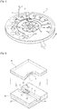
- FIG. 1 is a perspective view illustrating a microfluidic device according to an exemplary embodiment.
- a microfluidic device 10 according to the exemplary embodiment has a rotational disk type platform 20.
- the platform 20 may be formed using plastic materials such as acryl, polydimethylsiloxane (PDMS), etc., each of which is easily formable and has a biologically inactive surface.
- plastic materials such as acryl, polydimethylsiloxane (PDMS), etc., each of which is easily formable and has a biologically inactive surface.
- a raw material for fabrication of the platform is not particularly limited and may include any materials with chemical or biological stability, optical transparency and/or mechanical workability.
- the platform 20 may be formed of a multi-layered plate, and one or more chambers and one or more channels may be provided inside the platform by forming engraved structures corresponding to the chamber and the channel on a face at which one layer comes into contact with another layer, and then, adhering these structures to the face.
- the platform 20 may include, for example, a first plate 30 and a second plate 40 attached to the first plate.
- the first and second plates 30 and 40 may be formed using thermoplastic resin.
- the first plate 30 may be combined with the second plate 40 using adhesive or a double-sided adhesive tape, or other methods including ultrasonic welding, laser welding, and the like.
- the microfluidic device 10 includes at least one chamber 50 to receive a fluid, at least one channel 60 connected to the chamber 50 to provide a fluid path, and a valve unit 100 for opening and closing the channel so as to control a flow of the fluid. Furthermore, the microfluidic device 10 may be mounted on a spindle motor (not shown) for high speed rotation. A fixation hole 21 is formed in the center of the micro fluidic device 10 in order to fix the same to the spindle motor. A fluid remaining in the chamber 50 or channel 60 of the microfluidic device 10 is forced toward an outer circumference (or a periphery) of the platform 20, using centrifugal force generated by rotation of the spindle motor.
- the chamber 50, the channel 60 and/or the valve unit 100 are appropriately arranged for particular uses of the microfluidic device 10 in biochemical applications, for example, centrifugation of a fluid specimen, immunoserum response, genetic analysis, gene extraction, gene amplification, and so forth.
- alignment of the chamber 50, the channel 60 and the valve unit 100 is not particularly limited but may have a number of designs in consideration of use thereof.
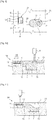
- FIG. 2 is a perspective view illustrating a valve unit according to an exemplary embodiment, with first and second plates separated from the valve unit
- FIG. 3 is a cross-sectional view along direction A-A shown in FIG. 2
- FIG. 4 is a cross-sectional view along direction B-B shown in FIG. 2 .
- valve unit according to the exemplary embodiment may be provided where the chamber meets the channel or anywhere along the length of the channel 60 of the microfluidic device 10. According to the foregoing exemplary embodiment, the valve unit provided in the middle of the channel is illustrated.
- the channel 60 includes a first region 61 which extends downward from a top of the first plate 30, a second region 62 which extends downward from the top of the first plate to a depth deeper than the first region 61 and comes into contact with an end of the first region 61 in stepwise manner, and a third region 63 which extends downward from the top of the first plate to a depth deeper than the first region 61 and comes into contact with the other end of the first region 61 in a stepwise manner.
- the second region 62 and the third region 63 have a depth D2 which is greater a depth D1 of the first region 61 Accordingly, a stepped structure 65 is formed in the first region 61 extending upward from a bottom of the channel 60.
- the valve unit 100 may include: a valve substance chamber 41 extending upward from a bottom of the second plate 40; a valve substance V to be received in a cured state in the valve substance chamber 41; a micro-channel part 110 which is provided above the stepped structure 65 formed in the first region 61 and through which the valve substance V fused in the valve substance chamber 41 by an external energy source flows to close a channel 60; and a fusion structure 120 which is protruded from the stepped structure 65 formed in the first region 61 and melts at a high temperature, enabling fused bonding of the micro-channel part 110.
- the valve substance chamber 41 has a uniform depth and is formed in a cylindrical shape on the second plate 40.
- the valve substance V is accommodated in the valve substance chamber 41 in a cured state.
- the valve substance V includes a phase transition material fused at a high temperature and a micro-exothermic material P including numerous particles which are dispersed in the phase transition material and absorb electromagnetic radiation from an external energy source 11 to generate heat.
- the valve substance chamber 41 may contain the fused valve substance V injected using a dispenser (not shown) and this substance may be cured.
- the valve substance V may be prepared by admixing the phase transition material with numerous micro-exothermic particles, that is, the micro-exothermic material P and, when cured, may be adhered to the valve substance chamber 41.
- the external energy source 11 for electromagnetic irradiation may be a laser source radiating a laser beam, a light emitting diode which radiates visible or infrared light, a xenon lamp, etc.
- the laser source may have at least one laser diode.
- the external energy source 11 may be selected on the basis of electromagnetic radiation wavelengths absorbed by the micro-exothermic material P contained in the valve substance V.
- the external energy source 11 may further include an adjustment unit (not shown) to regulate a position or direction of the energy source so as to concentrate electromagnetic radiation toward a desired area of the microfluidic device 10, that is, multiple valve substance chambers 51.
- This adjustment unit may be movable along a radius of the microfluidic device 10 and embodied by a variety of mechanisms. The adjustment unit will be readily known to persons skilled in the art and, therefore, a detailed description thereof will be omitted for brevity.
- the phase transition material may be wax which is fused by heating and transitions to a liquid phase, in turn being expanded in volume.
- the wax may include, for example, paraffin wax, microcrystalline wax, synthetic wax, natural wax, etc.
- the phase transition material may be a gel or thermoplastic resin.
- the gel may include, for example, polyacrylamide, polyacrylate, polymethacrylate, polyvinylamide, etc.
- the thermoplastic resin may be selected from cyclic olefin copolymer (COC), polymethylmethacrylate (PMMA), polycarbonate (PC), polystyrene (PS), polyoxymethylene (POM), perfluoralkoxy (PFA), polyvinylchloride (PVC), polypropylene (PP), polyethylene tetraphthalate (PET), polyetheretherketone (PEEK), polyamide (PA), polysulfone (PSU), polyvinylidene fluoride (PVDF), and the like.
- COC cyclic olefin copolymer
- PMMA polymethylmethacrylate
- PC polycarbonate
- PS polystyrene
- POM polyoxymethylene
- PFA perfluoralkoxy
- PVC polyvinylchlor
- the exothermic material P may include numerous particles, each having a diameter sufficiently small to freely pass through a micro-channel 60.
- the particles may have a diameter of 1 nm to 100 ⁇ m.
- the micro-exothermic material P is heated to rapidly elevate a temperature and generates heat when electromagnetic energy is provided by a laser, and is uniformly dispersed into the wax.
- the micro-exothermic material may have a core containing metal components and a hydrophobic shell structure.
- the micro-exothermic material may have an Fe based core and a specific molecular structure including plural surfactant components to be bonded to Fe in order to enclose the Fe.
- the micro-exothermic material P may be stored in a dispersed state in a carrier oil.
- the carrier oil may also be hydrophobic.
- the carrier oil containing the micro-exothermic material P dispersed therein is homogeneously mixed with a fused phase transition material, resulting in the valve substance V.
- the micro-exothermic material P is not particularly limited to polymer beads, but may include at least one selected from quantum dots, magnetic beads, gold nanoparticles, silver nanoparticles, beads with metal composition, carbon particles, etc.
- the carbon particles may further include graphite granules.
- the micro-exothermic material P may be, for example, metal oxide particles such as Al 2 O 3 , TiO 2 , Ta 2 O 3 , Fe 2 O 3 , Fe 3 O 4 , HfO 2 , and the like.
- the micro-exothermic material P may include a dye to absorb external electromagnetic radiation with a constant spectrum to generate heat.
- the dye is not particularly limited so long as the dye is a material having a structure miscible with the phase transition material.
- dyes with optical properties such as ADS905AM, infrared dyes such as a dye represented by C 62 H 96 N 6 SbF 6 or Epolight2057 available from American Dye Source Inc., infrared dyes having absorption spectra suitable for near infrared sources available from Epolin Inc., and other dyes such as Epolight2180, Epolight 2189, carbon black, and so forth, may be employed.
- the valve unit 100 is a normally open valve that normally leaves the channel 60 open and closes the channel 60 using the valve substance V when electromagnetic energy is emitted to the valve substance V contained in the valve substance chamber 41.
- a laser source 11 is an example of the energy source 11 and emits a laser L toward the valve substance V, in turn providing energy to the same.
- the laser source 11 may include a laser diode.
- a part of the first region 61 is alternately aligned with the valve substance chamber 41 while the other part of the first region 61 is overlapped with the valve substance chamber 41.
- the overlapping part of the first region 61 is referred to as an overlap part 61a and the other part is referred to as a non-overlap part 61b.
- a width and a stagger degree between the first region 61 and the valve substance chamber 41 may be set to form the non-overlap part 61b at each side of the valve substance 41.
- the width and the stagger degree between the first region 61 and the valve substance chamber 41 may be set to form the non-overlap part 61b at either side of the valve substance chamber 41.
- the fused valve substance V When the valve substance V in the valve substance chamber 41 is fused, the fused valve substance V partially shifts to the channel 60 corresponding to the non-overlap part 61b by capillary action, in turn closing the channel 60, since a cross-sectional area of the channel 60 in the non-overlap part 61b is narrower than that of the channel 60 in the overlap part 61a.
- the non-overlap part 61b of the channel 60 may correspond to the micro-channel part 110.
- the fusion structure 120 is formed and protruded toward the second plate 40.
- the fusion structure 120 is formed using a resin material and melts at a predetermined temperature or more. Applying electromagnetic energy to a site corresponding to the fusion structure 120 outside of the microfluidic device 10, a temperature of the valve substance V coming into contact with the fusion structure 120 is elevated to at least a melting point of the fusion structure 120 and allows melting of the fusion structure, in turn enabling fused bonding of the micro-channel part 110. That is, the fusion structure 120 functions as a melting bump fused by heat.
- the height D1 of the micro-channel part may range from 5 to 100 ⁇ m.
- the fusion structure 120 may include at least one first fusion structure 121 extended in a flow direction of a fluid not to prevent the fluid flow in the channel 60 and at least one second fusion structure 122 protruded inward of the channel from a lateral side 61c of the first region 61.
- At least one first fusion structure 121 may be formed along direction B-B shown in FIG. 2 and, for example, two first fusion structures 121 are illustrated according to the exemplary embodiment.
- At least one second fusion structure 122 may be formed along direction A-A shown in FIG. 2 , for example, three second fusion structures 122 are illustrated according to the exemplary embodiment.
- the second fusion structure 122 may take various forms, although the second fusion structure 122 according to the exemplary embodiment has a semi-cylindrical shape. Since the second fusion structure 122 is provided on the lateral side 61c, a decrease in a fused bonding property at the lateral side of the first region 61 may be inhibited during fused bonding.
- a height of the fusion structure 120 may be substantially the same as the depth D1 of the first region 61 (that is, the height of micro-channel part) or, otherwise, be protruded to a desired level in a range of higher than a top of the first region 61 and up to the height D1 of the micro-channel part 110.
- FIGS. 5 and 6 are cross-sectional views illustrating a fusion structure of a valve unit according to an exemplary embodiment.
- a fusion structure 220 is not formed on a first plate 30' but may be protruded downward from a bottom of a second plate 40'.
- a first fusion structure 221 and a second fusion structure 222 which correspond to that described in the foregoing exemplary embodiment may be provided on the bottom of the second plate 40'.
- fusion structures 320 may be protruded from a top of the first region 61' and a bottom of the second plate 40", respectively.
- shape, size and/or number of the fusion structures 220 and 230 is suitably selected according to practical experiments, so as to prevent fluid flow from being interrupted in a normally open condition while attaining optimum fused bonding effects.
- the fusion structures 220 and 320 may be prepared using the same material as employed for the first plates 30 and 30' and/or the second plates 40, 40' and 40" and integrated with the same when the plates are injection molded.
- FIG. 11 is a cross-sectional view illustrating operation of a valve unit according to an exemplary embodiment
- FIG. 11 is a cross-sectional view illustrating a channel closed by a valve unit according to an exemplary embodiment.
- FIG. 3 shows the valve substance chamber 41 containing a valve substance therein.
- the fused substance V when the valve substance V is fused by applying energy through laser irradiation, the fused substance V partially flows from the valve substance chamber 41 into the non-overlap part 61b of the first region 61 (that is, the micro-channel part) by capillary action and remains therein, as shown in FIG. 11 .
- the micro-exothermic material P in the valve substance V generates heat by continuous electromagnetic irradiation and a temperature of the valve substance V is elevated to at least a melting point of the fusion structure 120, in turn melting the fusion structure 120 by the valve substance V remaining in the non-overlap part 61b.
- valve substance V and the fusion structure 120 are cured to form a fused part W and the first and second plates 30 and 40 are fused and bonded in the non-overlap part 61b (that is, the micro-channel part), in turn closing the channel 60, as shown in FIG. 11 .
- the valve substance V is heated by laser irradiation one time at a certain position and flows into the non-overlap part 61b, and then, the valve substance V may undergo heating again so as to melt the fusion structure 120, thereby enabling fused bonding of the non-overlap part 61b.
- laser irradiation may be performed once at a single position so as to move the valve substance V to the non-overlap part 61b and enable fused bonding of the non-overlap part 61b.
- valve substance chamber 41 is subjected to laser irradiation to flow the valve substance V toward the non-overlap part 61b and, before the fusion structure 120 melts, the valve substance V is cured again by controlling the energy supplied to the fusion structure so as to close the channel 60. In such closed channel conditions, sample inspection may be performed.
- the micro-exothermic material P is heated by installing the laser outside of the microfluidic device 10 corresponding to the non-overlap part 61b and conducting electromagnetic irradiation and the valve substance V is fused at a high temperature to melt the fusion structure 120, in turn enabling fused bonding of the non-overlap part 61b. That is, the non-overlap part 61b may be selectively fused and bonded according to requirements.
- this process of fusing the valve substance V and flowing the same to the non-overlap part 61b may be performed using a heater (not shown) to heat the valve substance V without electromagnetic radiation, so as to fuse the valve substance V and guide the same to the non-overlap part 61b.
- valve substance V flowed to the non-overlap part 61b is subjected to laser irradiation to heat the micro-exothermic material P so as to heat and melt the fusion structure 120, in turn enabling fused bonding of the non-overlap part 61b and completely closing the channel 60.
- FIG. 11 is a cross-sectional view illustrating a valve unit according to another exemplary embodiment
- FIGS. 9 and 10 are cross-sectional views illustrating behavior of the valve unit according to another exemplary embodiment.
- valve unit of the present exemplary embodiment may be mounted on the same microfluidic device according to the previously described exemplary embodiment (hereafter referred to as 'first embodiment'), however, be formed in a different shape.
- 'first embodiment' the same microfluidic device according to the previously described exemplary embodiment
- the same numerical symbols are used and a detailed description thereof will be omitted for brevity.
- the valve unit 200 of the present exemplary embodiment includes: a valve substance chamber 130 engraved downward from a first plate 230 at a site adjacent to a channel 60; a valve substance V which is contained in a cured state in the valve substance chamber 130; a guidance channel 132 to guide the valve substance V, which was fused in the valve substance chamber 130 by an external energy source, toward the channel 60; a micro-channel part 110 provided above a first region 61 to receive the valve substance V having flowed from the guidance channel 132; and a fusion structure 120 protruded from the first region 61, which melts at a high temperature to enable fused bonding of the micro-channel part 110.
- the valve substance chamber 130 is connected to the middle of the channel 60 and receives the valve substance V, wherein the valve substance V is initially in a solid state in the valve substance chamber 130 at room temperature and is then fused and expanded by heating in order to flow into the channel 60 via the guidance channel 132, and lastly, solidified again in the channel 60 to block fluid flow in the same.
- valve substance V is prepared as described in the first embodiment and the energy source used for electromagnetic irradiation of the valve substance V is substantially the same as described in the first embodiment.
- the fused valve substance V flows into the micro-channel part 110 by capillary action since a cross-sectional area of the channel 60 in the micro-channel part 110 is smaller than that of the guidance channel 132, so as to close the channel 60.
- the cross-sectional area of the guidance channel 132 is not particularly limited so long as the guidance channel 132 functions to guide the fused valve substance V to the micro-channel part 110.
- a second plate 240 may have a through hole 131 corresponding to the valve substance chamber 130 so as to facilitate electromagnetic irradiation of the valve substance V.
- the fusion structure 120 may be protruded from a top of the first region 61 which is substantially the same as described in the first embodiment or the modified embodiment.
- a shape, size and/or number of the fusion structure 120 may be suitably selected to prevent a fluid flow from being interrupted when the fusion structure is normally open, while attaining optimum fused bonding effects.
- the micro-exothermic material P absorbs electromagnetic radiation to heat the phase transition material.
- the valve substance V is fused and expanded in volume, and flows into the micro-channel part 110 formed in the first region 61 of the channel 60, via the guidance channel 132.
- the valve substance V having flowed into the micro-channel part 110 is heated up to at least a melting point of the fusion structure 120 by electromagnetic radiation in order to melt the fusion structure 120 and enable fused bonding of the micro-channel part 110, in turn permanently closing the channel 60.
- valve unit according to the second embodiment may be driven by the same process applied to the valve unit according to the first embodiment.
- the valve substance chamber is provided in the second plate and, if a microfluidic device configured with a complicated flow path is used, the flow path is easily arranged.
- the valve substance chamber is provided in the first plate so as to reduce a thickness of the second plate, thereby fabricating a microfluidic device with a more compact configuration.
Landscapes
- Chemical & Material Sciences (AREA)
- Engineering & Computer Science (AREA)
- General Engineering & Computer Science (AREA)
- Dispersion Chemistry (AREA)
- Health & Medical Sciences (AREA)
- Mechanical Engineering (AREA)
- Analytical Chemistry (AREA)
- General Health & Medical Sciences (AREA)
- Chemical Kinetics & Catalysis (AREA)
- Immunology (AREA)
- Hematology (AREA)
- Physics & Mathematics (AREA)
- Life Sciences & Earth Sciences (AREA)
- Biochemistry (AREA)
- General Physics & Mathematics (AREA)
- Clinical Laboratory Science (AREA)
- Pathology (AREA)
- Micromachines (AREA)
- Temperature-Responsive Valves (AREA)
- Physical Or Chemical Processes And Apparatus (AREA)
- Automatic Analysis And Handling Materials Therefor (AREA)
- Safety Valves (AREA)
Claims (15)
- Ventileinheit zum Öffnen und Schließen eines Kanals, der einen Strömungsweg einer Flüssigkeit zur Verfügung stellt, wobei die Ventileinheit umfasst:einen Kanal (60);eine Ventilsubstanz (v), die ein Phasenübergangsmaterial umfasst;eine Ventilsubstanzkammer (41), die mit dem Kanal in Verbindung steht und die Ventilsubstanz empfängt;einen Mikrokanalteil (110), der in dem Kanal (60) angeordnet ist; gekennzeichnet durch:eine in dem Mikrokanalteil ausgeformte Verschmelzungsstruktur (120),wobei die Ventilsubstanz, die in der Ventilsubstanzkammer (41) enthalten ist, durch angelegte Energie verschmolzen wird und in den Mikrokanalteil (110) strömt, und die Ventilsubstanz in dem Mikrokanalteil erhitzt wird, um die Verschmelzungsstruktur zu schmelzen und eine Schmelzverbindung des Kanals durchzuführen, die ihrerseits den Kanal schließt.
- Ventileinheit gemäß Anspruch 1, wobei die Ventileinheit an einer mikrofluidischen Vorrichtung (20) vom Typ Drehscheibe angeordnet ist, und die mikrofluidische Vorrichtung eine erste Platte (30) und eine zweite Platte (40), die mit der ersten Platte kombiniert ist, um den Kanal von der Ventilsubstanzkammer zu trennen, umfasst.
- Ventileinheit gemäß Anspruch 1, die weiterhin einen Führungskanal (132) umfasst, um die verschmolzene Ventilsubstanz in den Mikrokanalteil zu führen, wenn die Ventilsubstanz in der Ventilsubstanzkammer verschmolzen worden ist.
- Ventileinheit gemäß Anspruch 1, wobei die Verschmelzungsstruktur wenigstens eine erste Verschmelzungsstruktur (121) umfasst, die von dem Mikrokanalteil hervorsteht und sich in einer Strömungsrichtung der Flüssigkeit erstreckt.
- Ventileinheit gemäß Anspruch 4, wobei die Verschmelzungsstruktur eine zweite Verschmelzungsstruktur (122) umfasst, die von einem seitlichen Abschnitt des Mikrokanalteils hervorsteht.
- Ventileinheit gemäß Anspruch 2, wobei die erste (30) und die zweite (40) Platte aus thermoplastischem Kunstharz ausgeformt sind.
- Ventileinheit gemäß Anspruch 1, wobei die Ventilsubstanz (v) ein mikroexothermes Material umfasst, das in dem Phasenübergangsmaterial dispergiert ist und elektromagnetische Strahlung absorbiert, um Wärmeenergie zu emittieren.
- Ventileinheit gemäß Anspruch 7, wobei es sich bei dem mikroexothermen Material um wenigstens ein Material handelt, das aus der folgenden Gruppe ausgewählt wird: Polymerperlen, Quantenpunkte, Goldnanopartikel, Silbernanopartikel, Metallverbindungsperlen, Kohlenstoffpartikel und magnetische Perlen.
- Ventileinheit gemäß Anspruch 7, wobei es sich bei dem mikroexothermen Material um Metalloxidpartikel handelt.
- Ventileinheit gemäß Anspruch 7, wobei das mikroexotherme Material Farben umfasst, die als Reaktion auf elektromagnetische Strahlung Wärme erzeugen.
- Ventileinheit gemäß Anspruch 1, wobei es sich bei dem Phasenübergangsmaterial um wenigstens ein Material handelt, das aus der folgenden Gruppe ausgewählt wird: Wachs, Gel und thermoplastische Kunstharze.
- Ventileinheit gemäß Anspruch 11, wobei das Wachs wenigstens ein Wachs umfasst, das aus der folgenden Gruppe ausgewählt wird: Paraffinwachs, mikrokristallines Wachs, synthetisches Wachs und natürliches Wachs.
- Ventileinheit gemäß Anspruch 11, wobei das Gel wenigstens ein Gel umfasst, das aus der folgenden Gruppe ausgewählt wird: Polyacrylamid, Polyacrylat, Polymethacrylat und Polyvinylamid.
- Ventileinheit gemäß Anspruch 11, wobei das thermoplastische Kunstharz wenigstens ein Harz umfasst, das aus der folgenden Gruppe ausgewählt wird: Cycloolefincopolymer (COC), Polymethylmethacrylat (PMMA), Polycarbonat (PC), Polystyrol (PS), Polyoxymethylen (POM), Perfluoralkoxy (PFA), Polyvinylchlorid (PVC), Polypropylen (PP), Polyethylenterephthalat (PET), Polyetheretherketon (PEEK), Polyamid (PA), Polysulfon (PSU) und Polyvinylidenfluorid (PVDF).
- Ventileinheit gemäß Anspruch 1, wobei der Mikrokanalteil (110) in einem konstanten Abschnitt des Kanals (60) ausgeformt ist und einen kleineren Querschnittsbereich als der Kanal aufweist.
Applications Claiming Priority (2)
| Application Number | Priority Date | Filing Date | Title |
|---|---|---|---|
| KR1020090105349A KR101130698B1 (ko) | 2009-11-03 | 2009-11-03 | 밸브 유닛과 이를 구비한 미세유동장치 및 밸브 유닛의 구동방법 |
| PCT/KR2010/007601 WO2011055942A2 (en) | 2009-11-03 | 2010-11-01 | Valve unit, microfluidic device having the same, and method of driving the valve unit |
Publications (3)
| Publication Number | Publication Date |
|---|---|
| EP2496949A2 EP2496949A2 (de) | 2012-09-12 |
| EP2496949A4 EP2496949A4 (de) | 2016-12-28 |
| EP2496949B1 true EP2496949B1 (de) | 2018-01-10 |
Family
ID=43924109
Family Applications (1)
| Application Number | Title | Priority Date | Filing Date |
|---|---|---|---|
| EP10828477.9A Not-in-force EP2496949B1 (de) | 2009-11-03 | 2010-11-01 | Ventileinheit, mikrofluidische vorrichtung damit sowie antriebsverfahren für die ventileinheit |
Country Status (7)
| Country | Link |
|---|---|
| US (1) | US8490655B2 (de) |
| EP (1) | EP2496949B1 (de) |
| JP (1) | JP5600180B2 (de) |
| KR (1) | KR101130698B1 (de) |
| CN (1) | CN102597786B (de) |
| CA (1) | CA2779907A1 (de) |
| WO (1) | WO2011055942A2 (de) |
Families Citing this family (18)
| Publication number | Priority date | Publication date | Assignee | Title |
|---|---|---|---|---|
| US8062738B2 (en) * | 2007-09-07 | 2011-11-22 | Samsung Electronics Co., Ltd. | Heat transfer medium and heat transfer method using the same |
| US20120314528A1 (en) * | 2011-06-08 | 2012-12-13 | Albert-Ludwigs-Universitaet Freiburg | Device, fluidic module and method for producing a dilution series |
| WO2013106480A1 (en) * | 2012-01-09 | 2013-07-18 | The Regents Of The University Of California | Measurement of rheological properties using microprobes |
| CA2886404A1 (en) | 2012-09-27 | 2014-04-03 | Rhodia Operations | Process for making silver nanostructures and copolymer useful in such process |
| KR102176587B1 (ko) * | 2013-10-15 | 2020-11-10 | 삼성전자주식회사 | 시료분석장치, 시료분석방법, 및 밸브의 동적 작동 방법 |
| US9995411B1 (en) * | 2014-07-16 | 2018-06-12 | National Technology & Engineering Solutions Of Sandia, Llc | High-temperature, adhesive-based microvalves and uses thereof |
| GB2531266A (en) * | 2014-10-13 | 2016-04-20 | Graviner Ltd Kidde | Frangible diaphragm for use in a valve mechanism |
| DE102015204235B4 (de) * | 2015-03-10 | 2016-12-15 | Fraunhofer-Gesellschaft zur Förderung der angewandten Forschung e.V. | Fluidikstruktur mit Halteabschnitt und Verfahren zum Vereinigen zweier Flüssigkeitsvolumina |
| US20180311670A1 (en) * | 2015-11-30 | 2018-11-01 | Biocartis Nv | Fluidic path sealing and cutting device |
| CN107676542B (zh) * | 2017-09-20 | 2018-12-25 | 北京工业大学 | 一种基于电阻加热的非接触式常闭型相变微阀 |
| KR20200009859A (ko) * | 2018-07-20 | 2020-01-30 | 재단법인대구경북과학기술원 | 원심 밸브 제어 장치 |
| CN109553980B (zh) * | 2018-12-29 | 2021-03-16 | 西安交通大学 | 一种基于磁性颗粒掺杂温敏大变形材料及制备方法 |
| CN109555872A (zh) * | 2018-12-29 | 2019-04-02 | 西安交通大学 | 一种基于磁性温敏大变形材料的温控限流方法 |
| CN110886901B (zh) * | 2019-11-20 | 2021-06-08 | 东莞市东阳光诊断产品有限公司 | 基板、相变阀及其控制方法 |
| WO2021240209A1 (en) * | 2020-05-26 | 2021-12-02 | Crestoptics S.P.A. | Device and method for detecting a target molecule in a biological fluid |
| WO2022074782A1 (ja) | 2020-10-08 | 2022-04-14 | アイ ピース, インコーポレイテッド | バルブ |
| US20240033726A1 (en) * | 2020-12-22 | 2024-02-01 | Oxford Immune Algorithmics Ltd | Wafer for carrying biological sample |
| KR102731456B1 (ko) * | 2021-03-31 | 2024-11-18 | 주식회사 씨티셀즈 | 세포 분리 제어 장치 |
Family Cites Families (32)
| Publication number | Priority date | Publication date | Assignee | Title |
|---|---|---|---|---|
| US6048734A (en) * | 1995-09-15 | 2000-04-11 | The Regents Of The University Of Michigan | Thermal microvalves in a fluid flow method |
| DE19749011A1 (de) * | 1996-11-19 | 1998-05-20 | Lang Volker | Mikroventil |
| SE9902474D0 (sv) * | 1999-06-30 | 1999-06-30 | Amersham Pharm Biotech Ab | Polymer valves |
| US6561479B1 (en) * | 2000-08-23 | 2003-05-13 | Micron Technology, Inc. | Small scale actuators and methods for their formation and use |
| US7125510B2 (en) * | 2002-05-15 | 2006-10-24 | Zhili Huang | Microstructure fabrication and microsystem integration |
| JP2006010340A (ja) * | 2004-06-22 | 2006-01-12 | Sekisui Chem Co Ltd | マイクロ全分析システム |
| US20060002817A1 (en) * | 2004-06-30 | 2006-01-05 | Sebastian Bohm | Flow modulation devices |
| WO2006064949A1 (ja) * | 2004-12-17 | 2006-06-22 | Brother Kogyo Kabushiki Kaisha | キャピラリーエレクトロウェッティング現象を用いたバルブ及びアクチュエータ |
| CN101137440A (zh) * | 2005-01-12 | 2008-03-05 | 因弗因斯医药瑞士股份有限公司 | 制备微流体器件的方法和微流体器件 |
| KR100668335B1 (ko) * | 2005-04-02 | 2007-01-12 | 삼성전자주식회사 | 자성 왁스 플러그를 구비한 마이크로 밸브 및 자성 왁스를이용한 유동 제어 방법 |
| US20070092409A1 (en) * | 2005-10-21 | 2007-04-26 | Beatty Christopher C | Reconfigurable valve using optically active material |
| EP1790861A1 (de) * | 2005-11-25 | 2007-05-30 | Bonsens AB | Mikrofluidisches System |
| KR100763923B1 (ko) * | 2006-08-04 | 2007-10-05 | 삼성전자주식회사 | 폐쇄밸브 유닛 및 이를 구비한 반응장치 |
| US7998433B2 (en) * | 2006-04-04 | 2011-08-16 | Samsung Electronics Co., Ltd. | Valve unit and apparatus having the same |
| KR100738113B1 (ko) * | 2006-05-10 | 2007-07-12 | 삼성전자주식회사 | 상전이형 밸브 및 그 제작방법 |
| EP1884284A1 (de) * | 2006-08-04 | 2008-02-06 | Samsung Electronics Co., Ltd. | Absperrventileinheit und Reaktionsvorrichtung mit Absperrventil |
| US20080031782A1 (en) * | 2006-08-07 | 2008-02-07 | Timothy Beerling | Microfluidic device with valve and method |
| KR101422572B1 (ko) * | 2006-09-05 | 2014-07-30 | 삼성전자주식회사 | 핵산 검출을 위한 원심력 기반의 미세유동장치 및 이를포함하는 미세유동시스템 |
| KR101343034B1 (ko) * | 2006-09-05 | 2013-12-18 | 삼성전자 주식회사 | 원심력 기반의 단백질 검출용 미세유동 장치 및 이를포함하는 미세유동 시스템 |
| KR100846501B1 (ko) * | 2006-11-09 | 2008-07-17 | 삼성전자주식회사 | 밸브 유닛 및 이를 구비한 유체 처리 장치 |
| KR101228112B1 (ko) * | 2006-12-06 | 2013-01-31 | 삼성전자주식회사 | 원심력과 펌프를 이용해 유체의 이동을 제어하는 미세유동장치 및 이를 포함하는 미세유동 시스템 |
| KR20080073934A (ko) * | 2007-02-07 | 2008-08-12 | 삼성전자주식회사 | 밸브 충전물 및 이를 구비한 밸브 유닛 |
| KR101305976B1 (ko) * | 2007-02-12 | 2013-09-12 | 삼성전자주식회사 | 연속희석을 위한 원심력 기반의 미세유동장치 및 이를포함하는 미세유동시스템 |
| US8191715B2 (en) * | 2007-04-02 | 2012-06-05 | Samsung Electronics Co., Ltd. | Centrifugal force-based microfluidic device and microfluidic system including the same |
| KR101258434B1 (ko) * | 2007-05-03 | 2013-05-02 | 삼성전자주식회사 | 미세유동 시스템 및,이의 제조방법 |
| KR101391736B1 (ko) * | 2007-08-07 | 2014-05-07 | 삼성전자주식회사 | 미세유동 밸브, 상기 미세유동 밸브의 제조 방법 및 상기미세유동 밸브를 포함하는 미세유동 장치 |
| US7980272B2 (en) * | 2007-06-21 | 2011-07-19 | Samsung Electronics Co., Ltd. | Microfluidic valve, method of manufacturing the same, and microfluidic device comprising the microfluidic valve |
| KR101473871B1 (ko) * | 2007-06-21 | 2014-12-17 | 삼성전자 주식회사 | 미세유체 제어용 밸브 유닛의 제조방법, 미세유체 제어용밸브 유닛 및, 상기 밸브 유닛을 구비한 미세유동 장치 |
| WO2009013321A2 (en) * | 2007-07-23 | 2009-01-29 | Clondiag Gmbh | Assays |
| KR101335727B1 (ko) * | 2007-08-22 | 2013-12-04 | 삼성전자주식회사 | 원심력 기반의 혈액 검사용 디스크형 미세유동장치 |
| KR20090057691A (ko) * | 2007-12-03 | 2009-06-08 | 삼성전자주식회사 | 원심력 기반의 플랫폼, 이를 구비한 미세유동 시스템, 및상기 플랫폼의 홈 위치 결정 방법 |
| KR100919400B1 (ko) * | 2008-04-07 | 2009-09-29 | 삼성전자주식회사 | 미세유동장치 및 그 제조방법 |
-
2009
- 2009-11-03 KR KR1020090105349A patent/KR101130698B1/ko active Active
-
2010
- 2010-11-01 JP JP2012537801A patent/JP5600180B2/ja active Active
- 2010-11-01 CA CA2779907A patent/CA2779907A1/en not_active Abandoned
- 2010-11-01 WO PCT/KR2010/007601 patent/WO2011055942A2/en not_active Ceased
- 2010-11-01 EP EP10828477.9A patent/EP2496949B1/de not_active Not-in-force
- 2010-11-01 CN CN201080049897.7A patent/CN102597786B/zh not_active Expired - Fee Related
- 2010-11-03 US US12/938,777 patent/US8490655B2/en active Active
Non-Patent Citations (1)
| Title |
|---|
| None * |
Also Published As
| Publication number | Publication date |
|---|---|
| KR20110048673A (ko) | 2011-05-12 |
| WO2011055942A3 (en) | 2011-07-14 |
| US20110100476A1 (en) | 2011-05-05 |
| EP2496949A4 (de) | 2016-12-28 |
| EP2496949A2 (de) | 2012-09-12 |
| CN102597786A (zh) | 2012-07-18 |
| CA2779907A1 (en) | 2011-05-12 |
| JP2013510306A (ja) | 2013-03-21 |
| CN102597786B (zh) | 2014-09-17 |
| KR101130698B1 (ko) | 2012-04-02 |
| WO2011055942A2 (en) | 2011-05-12 |
| JP5600180B2 (ja) | 2014-10-01 |
| US8490655B2 (en) | 2013-07-23 |
Similar Documents
| Publication | Publication Date | Title |
|---|---|---|
| EP2496949B1 (de) | Ventileinheit, mikrofluidische vorrichtung damit sowie antriebsverfahren für die ventileinheit | |
| KR101258434B1 (ko) | 미세유동 시스템 및,이의 제조방법 | |
| EP1920843B1 (de) | Ventileinheit, Mikrofluidvorrichtung mit der Ventileinheit und mikrofluidisches Substrat | |
| EP2324924B1 (de) | Mikrofluidisches system | |
| EP1980322B1 (de) | Mikrofluidische Vorrichtung auf Zentrifugalkraftbasis und mikrofluidisches System | |
| KR100858091B1 (ko) | 시료 분배 구조를 갖는 원심력 기반의 미세유동장치 및이를 포함하는 미세유동시스템 | |
| US7951332B2 (en) | Centrifugal force based microfluidic device for dilution and microfluidic system including the same | |
| KR101578149B1 (ko) | 미세유체 제어용 밸브 유닛, 및 이의 제조방법 | |
| CN101126465B (zh) | 阀单元,具有该阀单元的反应装置以及在通道中形成阀的方法 | |
| KR101391736B1 (ko) | 미세유동 밸브, 상기 미세유동 밸브의 제조 방법 및 상기미세유동 밸브를 포함하는 미세유동 장치 | |
| KR100955481B1 (ko) | 밸브 유닛, 이를 구비한 미세유동장치, 및 상기 밸브유닛의 제조방법 | |
| KR20080112573A (ko) | 미세유체 제어용 밸브 유닛의 제조방법, 미세유체 제어용밸브 유닛 및, 상기 밸브 유닛을 구비한 미세유동 장치 |
Legal Events
| Date | Code | Title | Description |
|---|---|---|---|
| PUAI | Public reference made under article 153(3) epc to a published international application that has entered the european phase |
Free format text: ORIGINAL CODE: 0009012 |
|
| 17P | Request for examination filed |
Effective date: 20120502 |
|
| AK | Designated contracting states |
Kind code of ref document: A2 Designated state(s): AL AT BE BG CH CY CZ DE DK EE ES FI FR GB GR HR HU IE IS IT LI LT LU LV MC MK MT NL NO PL PT RO RS SE SI SK SM TR |
|
| RAP1 | Party data changed (applicant data changed or rights of an application transferred) |
Owner name: SAMSUNG ELECTRONICS CO., LTD. |
|
| DAX | Request for extension of the european patent (deleted) | ||
| A4 | Supplementary search report drawn up and despatched |
Effective date: 20161129 |
|
| RIC1 | Information provided on ipc code assigned before grant |
Ipc: F16K 99/00 20060101ALI20161123BHEP Ipc: G01N 37/00 20060101ALI20161123BHEP Ipc: G01N 35/08 20060101AFI20161123BHEP Ipc: B01L 3/00 20060101ALI20161123BHEP |
|
| GRAP | Despatch of communication of intention to grant a patent |
Free format text: ORIGINAL CODE: EPIDOSNIGR1 |
|
| INTG | Intention to grant announced |
Effective date: 20170830 |
|
| GRAS | Grant fee paid |
Free format text: ORIGINAL CODE: EPIDOSNIGR3 |
|
| GRAA | (expected) grant |
Free format text: ORIGINAL CODE: 0009210 |
|
| AK | Designated contracting states |
Kind code of ref document: B1 Designated state(s): AL AT BE BG CH CY CZ DE DK EE ES FI FR GB GR HR HU IE IS IT LI LT LU LV MC MK MT NL NO PL PT RO RS SE SI SK SM TR |
|
| REG | Reference to a national code |
Ref country code: GB Ref legal event code: FG4D |
|
| REG | Reference to a national code |
Ref country code: CH Ref legal event code: EP Ref country code: AT Ref legal event code: REF Ref document number: 962981 Country of ref document: AT Kind code of ref document: T Effective date: 20180115 |
|
| REG | Reference to a national code |
Ref country code: IE Ref legal event code: FG4D |
|
| REG | Reference to a national code |
Ref country code: DE Ref legal event code: R096 Ref document number: 602010048031 Country of ref document: DE |
|
| REG | Reference to a national code |
Ref country code: NL Ref legal event code: MP Effective date: 20180110 |
|
| REG | Reference to a national code |
Ref country code: AT Ref legal event code: MK05 Ref document number: 962981 Country of ref document: AT Kind code of ref document: T Effective date: 20180110 |
|
| PG25 | Lapsed in a contracting state [announced via postgrant information from national office to epo] |
Ref country code: NL Free format text: LAPSE BECAUSE OF FAILURE TO SUBMIT A TRANSLATION OF THE DESCRIPTION OR TO PAY THE FEE WITHIN THE PRESCRIBED TIME-LIMIT Effective date: 20180110 |
|
| PG25 | Lapsed in a contracting state [announced via postgrant information from national office to epo] |
Ref country code: FI Free format text: LAPSE BECAUSE OF FAILURE TO SUBMIT A TRANSLATION OF THE DESCRIPTION OR TO PAY THE FEE WITHIN THE PRESCRIBED TIME-LIMIT Effective date: 20180110 Ref country code: NO Free format text: LAPSE BECAUSE OF FAILURE TO SUBMIT A TRANSLATION OF THE DESCRIPTION OR TO PAY THE FEE WITHIN THE PRESCRIBED TIME-LIMIT Effective date: 20180410 Ref country code: LT Free format text: LAPSE BECAUSE OF FAILURE TO SUBMIT A TRANSLATION OF THE DESCRIPTION OR TO PAY THE FEE WITHIN THE PRESCRIBED TIME-LIMIT Effective date: 20180110 Ref country code: HR Free format text: LAPSE BECAUSE OF FAILURE TO SUBMIT A TRANSLATION OF THE DESCRIPTION OR TO PAY THE FEE WITHIN THE PRESCRIBED TIME-LIMIT Effective date: 20180110 Ref country code: CY Free format text: LAPSE BECAUSE OF FAILURE TO SUBMIT A TRANSLATION OF THE DESCRIPTION OR TO PAY THE FEE WITHIN THE PRESCRIBED TIME-LIMIT Effective date: 20180110 Ref country code: ES Free format text: LAPSE BECAUSE OF FAILURE TO SUBMIT A TRANSLATION OF THE DESCRIPTION OR TO PAY THE FEE WITHIN THE PRESCRIBED TIME-LIMIT Effective date: 20180110 |
|
| PG25 | Lapsed in a contracting state [announced via postgrant information from national office to epo] |
Ref country code: BG Free format text: LAPSE BECAUSE OF FAILURE TO SUBMIT A TRANSLATION OF THE DESCRIPTION OR TO PAY THE FEE WITHIN THE PRESCRIBED TIME-LIMIT Effective date: 20180410 Ref country code: GR Free format text: LAPSE BECAUSE OF FAILURE TO SUBMIT A TRANSLATION OF THE DESCRIPTION OR TO PAY THE FEE WITHIN THE PRESCRIBED TIME-LIMIT Effective date: 20180411 Ref country code: SE Free format text: LAPSE BECAUSE OF FAILURE TO SUBMIT A TRANSLATION OF THE DESCRIPTION OR TO PAY THE FEE WITHIN THE PRESCRIBED TIME-LIMIT Effective date: 20180110 Ref country code: LV Free format text: LAPSE BECAUSE OF FAILURE TO SUBMIT A TRANSLATION OF THE DESCRIPTION OR TO PAY THE FEE WITHIN THE PRESCRIBED TIME-LIMIT Effective date: 20180110 Ref country code: IS Free format text: LAPSE BECAUSE OF FAILURE TO SUBMIT A TRANSLATION OF THE DESCRIPTION OR TO PAY THE FEE WITHIN THE PRESCRIBED TIME-LIMIT Effective date: 20180510 Ref country code: AT Free format text: LAPSE BECAUSE OF FAILURE TO SUBMIT A TRANSLATION OF THE DESCRIPTION OR TO PAY THE FEE WITHIN THE PRESCRIBED TIME-LIMIT Effective date: 20180110 Ref country code: RS Free format text: LAPSE BECAUSE OF FAILURE TO SUBMIT A TRANSLATION OF THE DESCRIPTION OR TO PAY THE FEE WITHIN THE PRESCRIBED TIME-LIMIT Effective date: 20180110 Ref country code: PL Free format text: LAPSE BECAUSE OF FAILURE TO SUBMIT A TRANSLATION OF THE DESCRIPTION OR TO PAY THE FEE WITHIN THE PRESCRIBED TIME-LIMIT Effective date: 20180110 |
|
| REG | Reference to a national code |
Ref country code: DE Ref legal event code: R097 Ref document number: 602010048031 Country of ref document: DE |
|
| PG25 | Lapsed in a contracting state [announced via postgrant information from national office to epo] |
Ref country code: RO Free format text: LAPSE BECAUSE OF FAILURE TO SUBMIT A TRANSLATION OF THE DESCRIPTION OR TO PAY THE FEE WITHIN THE PRESCRIBED TIME-LIMIT Effective date: 20180110 Ref country code: EE Free format text: LAPSE BECAUSE OF FAILURE TO SUBMIT A TRANSLATION OF THE DESCRIPTION OR TO PAY THE FEE WITHIN THE PRESCRIBED TIME-LIMIT Effective date: 20180110 Ref country code: IT Free format text: LAPSE BECAUSE OF FAILURE TO SUBMIT A TRANSLATION OF THE DESCRIPTION OR TO PAY THE FEE WITHIN THE PRESCRIBED TIME-LIMIT Effective date: 20180110 Ref country code: AL Free format text: LAPSE BECAUSE OF FAILURE TO SUBMIT A TRANSLATION OF THE DESCRIPTION OR TO PAY THE FEE WITHIN THE PRESCRIBED TIME-LIMIT Effective date: 20180110 |
|
| PLBE | No opposition filed within time limit |
Free format text: ORIGINAL CODE: 0009261 |
|
| STAA | Information on the status of an ep patent application or granted ep patent |
Free format text: STATUS: NO OPPOSITION FILED WITHIN TIME LIMIT |
|
| PG25 | Lapsed in a contracting state [announced via postgrant information from national office to epo] |
Ref country code: SK Free format text: LAPSE BECAUSE OF FAILURE TO SUBMIT A TRANSLATION OF THE DESCRIPTION OR TO PAY THE FEE WITHIN THE PRESCRIBED TIME-LIMIT Effective date: 20180110 Ref country code: CZ Free format text: LAPSE BECAUSE OF FAILURE TO SUBMIT A TRANSLATION OF THE DESCRIPTION OR TO PAY THE FEE WITHIN THE PRESCRIBED TIME-LIMIT Effective date: 20180110 Ref country code: DK Free format text: LAPSE BECAUSE OF FAILURE TO SUBMIT A TRANSLATION OF THE DESCRIPTION OR TO PAY THE FEE WITHIN THE PRESCRIBED TIME-LIMIT Effective date: 20180110 Ref country code: SM Free format text: LAPSE BECAUSE OF FAILURE TO SUBMIT A TRANSLATION OF THE DESCRIPTION OR TO PAY THE FEE WITHIN THE PRESCRIBED TIME-LIMIT Effective date: 20180110 |
|
| 26N | No opposition filed |
Effective date: 20181011 |
|
| PGFP | Annual fee paid to national office [announced via postgrant information from national office to epo] |
Ref country code: DE Payment date: 20181126 Year of fee payment: 9 |
|
| PG25 | Lapsed in a contracting state [announced via postgrant information from national office to epo] |
Ref country code: SI Free format text: LAPSE BECAUSE OF FAILURE TO SUBMIT A TRANSLATION OF THE DESCRIPTION OR TO PAY THE FEE WITHIN THE PRESCRIBED TIME-LIMIT Effective date: 20180110 |
|
| PGFP | Annual fee paid to national office [announced via postgrant information from national office to epo] |
Ref country code: GB Payment date: 20181120 Year of fee payment: 9 |
|
| REG | Reference to a national code |
Ref country code: CH Ref legal event code: PL |
|
| PG25 | Lapsed in a contracting state [announced via postgrant information from national office to epo] |
Ref country code: LU Free format text: LAPSE BECAUSE OF NON-PAYMENT OF DUE FEES Effective date: 20181101 Ref country code: MC Free format text: LAPSE BECAUSE OF FAILURE TO SUBMIT A TRANSLATION OF THE DESCRIPTION OR TO PAY THE FEE WITHIN THE PRESCRIBED TIME-LIMIT Effective date: 20180110 |
|
| REG | Reference to a national code |
Ref country code: BE Ref legal event code: MM Effective date: 20181130 |
|
| REG | Reference to a national code |
Ref country code: IE Ref legal event code: MM4A |
|
| PG25 | Lapsed in a contracting state [announced via postgrant information from national office to epo] |
Ref country code: LI Free format text: LAPSE BECAUSE OF NON-PAYMENT OF DUE FEES Effective date: 20181130 Ref country code: CH Free format text: LAPSE BECAUSE OF NON-PAYMENT OF DUE FEES Effective date: 20181130 |
|
| PG25 | Lapsed in a contracting state [announced via postgrant information from national office to epo] |
Ref country code: IE Free format text: LAPSE BECAUSE OF NON-PAYMENT OF DUE FEES Effective date: 20181101 Ref country code: FR Free format text: LAPSE BECAUSE OF NON-PAYMENT OF DUE FEES Effective date: 20181130 |
|
| PG25 | Lapsed in a contracting state [announced via postgrant information from national office to epo] |
Ref country code: BE Free format text: LAPSE BECAUSE OF NON-PAYMENT OF DUE FEES Effective date: 20181130 |
|
| PG25 | Lapsed in a contracting state [announced via postgrant information from national office to epo] |
Ref country code: MT Free format text: LAPSE BECAUSE OF NON-PAYMENT OF DUE FEES Effective date: 20181101 |
|
| PG25 | Lapsed in a contracting state [announced via postgrant information from national office to epo] |
Ref country code: TR Free format text: LAPSE BECAUSE OF FAILURE TO SUBMIT A TRANSLATION OF THE DESCRIPTION OR TO PAY THE FEE WITHIN THE PRESCRIBED TIME-LIMIT Effective date: 20180110 |
|
| PG25 | Lapsed in a contracting state [announced via postgrant information from national office to epo] |
Ref country code: PT Free format text: LAPSE BECAUSE OF FAILURE TO SUBMIT A TRANSLATION OF THE DESCRIPTION OR TO PAY THE FEE WITHIN THE PRESCRIBED TIME-LIMIT Effective date: 20180110 |
|
| REG | Reference to a national code |
Ref country code: DE Ref legal event code: R119 Ref document number: 602010048031 Country of ref document: DE |
|
| PG25 | Lapsed in a contracting state [announced via postgrant information from national office to epo] |
Ref country code: MK Free format text: LAPSE BECAUSE OF NON-PAYMENT OF DUE FEES Effective date: 20180110 Ref country code: HU Free format text: LAPSE BECAUSE OF FAILURE TO SUBMIT A TRANSLATION OF THE DESCRIPTION OR TO PAY THE FEE WITHIN THE PRESCRIBED TIME-LIMIT; INVALID AB INITIO Effective date: 20101101 |
|
| GBPC | Gb: european patent ceased through non-payment of renewal fee |
Effective date: 20191101 |
|
| PG25 | Lapsed in a contracting state [announced via postgrant information from national office to epo] |
Ref country code: GB Free format text: LAPSE BECAUSE OF NON-PAYMENT OF DUE FEES Effective date: 20191101 Ref country code: DE Free format text: LAPSE BECAUSE OF NON-PAYMENT OF DUE FEES Effective date: 20200603 |