EP2496487B1 - Collapsible basket made of metal wire - Google Patents
Collapsible basket made of metal wire Download PDFInfo
- Publication number
- EP2496487B1 EP2496487B1 EP10787902.5A EP10787902A EP2496487B1 EP 2496487 B1 EP2496487 B1 EP 2496487B1 EP 10787902 A EP10787902 A EP 10787902A EP 2496487 B1 EP2496487 B1 EP 2496487B1
- Authority
- EP
- European Patent Office
- Prior art keywords
- frame
- wall
- bottom wall
- walls
- wire
- Prior art date
- Legal status (The legal status is an assumption and is not a legal conclusion. Google has not performed a legal analysis and makes no representation as to the accuracy of the status listed.)
- Active
Links
- 239000002184 metal Substances 0.000 title claims description 6
- 239000000463 material Substances 0.000 claims description 6
- 229920001187 thermosetting polymer Polymers 0.000 claims description 4
- 230000037431 insertion Effects 0.000 description 5
- 238000003780 insertion Methods 0.000 description 5
- 238000006073 displacement reaction Methods 0.000 description 2
- 230000007774 longterm Effects 0.000 description 2
- 238000004519 manufacturing process Methods 0.000 description 2
- 239000010813 municipal solid waste Substances 0.000 description 2
- 230000000295 complement effect Effects 0.000 description 1
- 125000006850 spacer group Chemical group 0.000 description 1
Images


Classifications
-
- B—PERFORMING OPERATIONS; TRANSPORTING
- B65—CONVEYING; PACKING; STORING; HANDLING THIN OR FILAMENTARY MATERIAL
- B65D—CONTAINERS FOR STORAGE OR TRANSPORT OF ARTICLES OR MATERIALS, e.g. BAGS, BARRELS, BOTTLES, BOXES, CANS, CARTONS, CRATES, DRUMS, JARS, TANKS, HOPPERS, FORWARDING CONTAINERS; ACCESSORIES, CLOSURES, OR FITTINGS THEREFOR; PACKAGING ELEMENTS; PACKAGES
- B65D7/00—Containers having bodies formed by interconnecting or uniting two or more rigid, or substantially rigid, components made wholly or mainly of metal
- B65D7/12—Containers having bodies formed by interconnecting or uniting two or more rigid, or substantially rigid, components made wholly or mainly of metal characterised by wall construction or by connections between walls
- B65D7/24—Containers having bodies formed by interconnecting or uniting two or more rigid, or substantially rigid, components made wholly or mainly of metal characterised by wall construction or by connections between walls collapsible, e.g. with all parts detachable
- B65D7/30—Fastening devices for holding collapsible containers in erected state, e.g. integral with container walls
-
- A—HUMAN NECESSITIES
- A47—FURNITURE; DOMESTIC ARTICLES OR APPLIANCES; COFFEE MILLS; SPICE MILLS; SUCTION CLEANERS IN GENERAL
- A47B—TABLES; DESKS; OFFICE FURNITURE; CABINETS; DRAWERS; GENERAL DETAILS OF FURNITURE
- A47B43/00—Cabinets, racks or shelf units, characterised by features enabling folding of the cabinet or the like
-
- A—HUMAN NECESSITIES
- A47—FURNITURE; DOMESTIC ARTICLES OR APPLIANCES; COFFEE MILLS; SPICE MILLS; SUCTION CLEANERS IN GENERAL
- A47B—TABLES; DESKS; OFFICE FURNITURE; CABINETS; DRAWERS; GENERAL DETAILS OF FURNITURE
- A47B55/00—Cabinets, racks or shelf units, having essential features of rigid construction
- A47B55/02—Cabinets, racks or shelf units, having essential features of rigid construction made of wire
-
- A—HUMAN NECESSITIES
- A47—FURNITURE; DOMESTIC ARTICLES OR APPLIANCES; COFFEE MILLS; SPICE MILLS; SUCTION CLEANERS IN GENERAL
- A47F—SPECIAL FURNITURE, FITTINGS, OR ACCESSORIES FOR SHOPS, STOREHOUSES, BARS, RESTAURANTS OR THE LIKE; PAYING COUNTERS
- A47F5/00—Show stands, hangers, or shelves characterised by their constructional features
- A47F5/10—Adjustable or foldable or dismountable display stands
- A47F5/13—Adjustable or foldable or dismountable display stands made of tubes or wire
-
- A—HUMAN NECESSITIES
- A47—FURNITURE; DOMESTIC ARTICLES OR APPLIANCES; COFFEE MILLS; SPICE MILLS; SUCTION CLEANERS IN GENERAL
- A47F—SPECIAL FURNITURE, FITTINGS, OR ACCESSORIES FOR SHOPS, STOREHOUSES, BARS, RESTAURANTS OR THE LIKE; PAYING COUNTERS
- A47F5/00—Show stands, hangers, or shelves characterised by their constructional features
- A47F5/14—Tubular connecting elements for wire stands
-
- B—PERFORMING OPERATIONS; TRANSPORTING
- B65—CONVEYING; PACKING; STORING; HANDLING THIN OR FILAMENTARY MATERIAL
- B65D—CONTAINERS FOR STORAGE OR TRANSPORT OF ARTICLES OR MATERIALS, e.g. BAGS, BARRELS, BOTTLES, BOXES, CANS, CARTONS, CRATES, DRUMS, JARS, TANKS, HOPPERS, FORWARDING CONTAINERS; ACCESSORIES, CLOSURES, OR FITTINGS THEREFOR; PACKAGING ELEMENTS; PACKAGES
- B65D21/00—Nestable, stackable or joinable containers; Containers of variable capacity
- B65D21/02—Containers specially shaped, or provided with fittings or attachments, to facilitate nesting, stacking, or joining together
- B65D21/0209—Containers specially shaped, or provided with fittings or attachments, to facilitate nesting, stacking, or joining together stackable or joined together one-upon-the-other in the upright or upside-down position
- B65D21/0211—Wire-mesh containers
-
- B—PERFORMING OPERATIONS; TRANSPORTING
- B65—CONVEYING; PACKING; STORING; HANDLING THIN OR FILAMENTARY MATERIAL
- B65D—CONTAINERS FOR STORAGE OR TRANSPORT OF ARTICLES OR MATERIALS, e.g. BAGS, BARRELS, BOTTLES, BOXES, CANS, CARTONS, CRATES, DRUMS, JARS, TANKS, HOPPERS, FORWARDING CONTAINERS; ACCESSORIES, CLOSURES, OR FITTINGS THEREFOR; PACKAGING ELEMENTS; PACKAGES
- B65D7/00—Containers having bodies formed by interconnecting or uniting two or more rigid, or substantially rigid, components made wholly or mainly of metal
- B65D7/12—Containers having bodies formed by interconnecting or uniting two or more rigid, or substantially rigid, components made wholly or mainly of metal characterised by wall construction or by connections between walls
- B65D7/14—Containers having bodies formed by interconnecting or uniting two or more rigid, or substantially rigid, components made wholly or mainly of metal characterised by wall construction or by connections between walls of skeleton or like apertured construction, e.g. baskets or carriers formed of wire mesh, of interconnected bands, bars, or rods, or of perforated sheet metal
- B65D7/20—Containers having bodies formed by interconnecting or uniting two or more rigid, or substantially rigid, components made wholly or mainly of metal characterised by wall construction or by connections between walls of skeleton or like apertured construction, e.g. baskets or carriers formed of wire mesh, of interconnected bands, bars, or rods, or of perforated sheet metal made of wire
-
- F—MECHANICAL ENGINEERING; LIGHTING; HEATING; WEAPONS; BLASTING
- F16—ENGINEERING ELEMENTS AND UNITS; GENERAL MEASURES FOR PRODUCING AND MAINTAINING EFFECTIVE FUNCTIONING OF MACHINES OR INSTALLATIONS; THERMAL INSULATION IN GENERAL
- F16B—DEVICES FOR FASTENING OR SECURING CONSTRUCTIONAL ELEMENTS OR MACHINE PARTS TOGETHER, e.g. NAILS, BOLTS, CIRCLIPS, CLAMPS, CLIPS OR WEDGES; JOINTS OR JOINTING
- F16B12/00—Jointing of furniture or the like, e.g. hidden from exterior
- F16B12/10—Jointing of furniture or the like, e.g. hidden from exterior using pegs, bolts, tenons, clamps, clips, or the like
- F16B12/28—Jointing of furniture or the like, e.g. hidden from exterior using pegs, bolts, tenons, clamps, clips, or the like for metal furniture parts
- F16B12/38—Jointing of furniture or the like, e.g. hidden from exterior using pegs, bolts, tenons, clamps, clips, or the like for metal furniture parts using snap-action elements
-
- F—MECHANICAL ENGINEERING; LIGHTING; HEATING; WEAPONS; BLASTING
- F16—ENGINEERING ELEMENTS AND UNITS; GENERAL MEASURES FOR PRODUCING AND MAINTAINING EFFECTIVE FUNCTIONING OF MACHINES OR INSTALLATIONS; THERMAL INSULATION IN GENERAL
- F16B—DEVICES FOR FASTENING OR SECURING CONSTRUCTIONAL ELEMENTS OR MACHINE PARTS TOGETHER, e.g. NAILS, BOLTS, CIRCLIPS, CLAMPS, CLIPS OR WEDGES; JOINTS OR JOINTING
- F16B2/00—Friction-grip releasable fastenings
- F16B2/20—Clips, i.e. with gripping action effected solely by the inherent resistance to deformation of the material of the fastening
- F16B2/22—Clips, i.e. with gripping action effected solely by the inherent resistance to deformation of the material of the fastening of resilient material, e.g. rubbery material
Definitions
- the present invention relates to wire baskets, including baskets used in store shelves for the retail sale of products.
- Some known baskets are formed of wire walls welded together to form a rigid container.
- the disadvantage is that these containers are bulky and therefore expensive to store and transport.
- wire baskets formed of separate elements assembled with plastic connecting pieces as described in GB 2 314 833 or NL 1020042 , or foldable as described in EP 1 454 833 .
- a major disadvantage of separate element trays is that items may be omitted or lost during manufacture, storage, or transportation and assembly of the items is expensive and subject to errors.
- a collapsible basket having no separable elements avoids this disadvantage.
- EP 1454833 the side walls, rear and front of the basket are pivotally mounted on the bottom wall, the pivots formed by U-shaped jumpers are welded to the frame of the bottom wall.
- the U-shaped jumpers are dimensioned so as to allow a certain amount of movement of the walls, in particular in a direction orthogonal to the plane of the bottom wall to allow the mounting and locking of the walls.
- the locking of the basket in mounted position is thus obtained by a vertical downward movement of the rear and front walls to engage their locking fingers in complementary locking holes of the side walls.
- a disadvantage of this known system is the risk of accidental or unintentional unlocking.
- Another disadvantage is the necessary clearance for mounting the trash that reduces its stability and creates noise during handling or use of the trash.
- an object of the invention is to provide wire baskets for the presentation of objects for sale in store shelves, small for transport and storage, easy to assemble, and stable in their mounting position
- a collapsible wire basket comprises a bottom wall, two side walls, a rear wall, a front wall, and fastening means for locking the side walls to the front and rear walls in the mounted position.
- Each of the walls comprises a wire frame and a grid, the front, rear and side walls being pivotally mounted to the bottom wall.
- the fastening means comprise insert locking parts, each of the locking parts comprising a first fixing part with a channel intended to be threaded onto a frame portion of a wall, and a second fixing part comprising configured elastic arms. for resiliently clamping a portion of the frame wire of the adjacent wall, the two fastening portions being integrally connected.
- the locking piece may advantageously be an injected piece of thermosetting plastic material.
- the inner surface of a wall forming the channel of the first fixing portion preferably comprises protuberances and optionally grooves or depressions at the foot of the protuberances, the protuberance being configured to be crushed during assembly on a frame portion, this for better resist the displacement of the locking element after mounting.
- the wall forming the channel of the first attachment portion may further include an opening to allow elastic deflection of the channel wall.
- the first fixing portion may advantageously comprise anti-rotation means.
- the anti-rotation means may be in the form of an extension intended to be fixed on a wire of the adjacent gate by a third fixing portion integrally connected to the first fixing portion.
- the third attachment portion includes resilient arms in the form of a "C” with a channel, configured to resiliently pinch a wire of the grid.
- the extension preferably comprises arms having a certain elasticity to improve the resilience of the "C" shaped clip.
- the anti-rotation means may be in the form of extensions extending generally in the direction of the axis of the channel projecting from an upper end of the channel.
- the frame of the bottom wall comprises, on each of its four sides, pivots, these pivots may be in the form of U-shaped jumpers made of wire and whose ends are welded to the frame.
- the jumpers on the front and rear sides of the frame advantageously extend into a direction parallel to the bottom wall, while the jumpers on the lateral sides of the frame extend in a direction orthogonal to the bottom wall, the front and rear walls being configured to be folded against the underside of the bottom wall and the side walls being configured to be folded over the upper surface of the bottom wall.
- the grid wires of the front and rear walls are welded to the frame on their inner faces and the wires of the grid of the bottom wall are welded to the frame of the bottom wall on its upper face.
- the upper side of the frame of the rear wall and the upper side of the frame of the front wall have lengths allowing them to fit into the perimeter of the frame of the bottom wall.
- the reported locking piece eliminates the clearance between the front, rear and side walls when locking the walls in the mounted position. Reduced pivoting also helps to make a basket more stable, rigid and less noisy to use than conventional folding bins.
- the lateral sides of the basket include keying elements compelling the user to mount the basket in one direction.
- the polarizing element may advantageously be formed by a section of transverse wire of the bottom wall which extend vertically offset the bottom wire of the side wall.
- This protrusion may also constitute a space releasing a zone to ensure the housing of the locking parts in the folded position. This space ensures, in transportation as in long-term storage, that the locking pieces are not supported on the side wires of the bottom wall.
- the wire section of the bottom wall is also laterally offset from the side wall.
- the son of the side wall frames comprising a corresponding offset to conform to the shape of the vertical extension of the wire of the bottom wall.
- the keying elements may have an inverted "V" shape, in order to allow stable stacking with a defined positioning of the bent baskets.
- the corresponding offsets of the side wall frames may include a transverse wire section on one side configured to interfere with the biasing member to stop rotation of the sidewall in the mounted position.
- the height of the rear wall may be less than the height of the side walls so as to provide support during a stack in the mounted position, that on the two side walls.
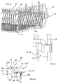
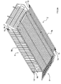
- a collapsible basket according to one embodiment of the invention comprises a bottom wall 1, a front wall 2, a rear wall 3, and side walls 4 and 5.
- Each of the walls comprises a metal frame 6, 7, 8, 9 formed (in the illustrated embodiment) of a folded thick wire, and a grid formed of a set of wires 13, 14 extending between the edges of the frame.
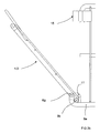
- the front wall 2 is of smaller height than the rear wall 3, so as to allow access to the products contained inside the basket, when an identical basket is stacked stacked on it or when the basket is hanging under the wall of a presentation ray.
- the frame 9 of each side wall 4, 5 has five sides with a vertical rear side 9a, a horizontal lower side 9b whose length corresponds to the depth of the bottom 1, a horizontal upper side 9e, a lower front side 9c inclined whose height is less than that of the rear side 6, and an upper front side inclined 9d interconnecting an end of the upper side 9e and that of the lower front side 9c.
- the height of the vertical side 9a may correspond to that of the rear wall 3 as illustrated in the variant of FIG. figure 1a , or may advantageously have a height slightly greater than that of the rear wall as shown in FIG. figure 8a . This improves the seating and the stability of the stacked baskets by ensuring that the supports are only under the two side walls.
- the side wall 5 is symmetrical to the side wall 4 with respect to a median vertical plane.
- the frame of the bottom wall 1 of the basket comprises, on each of its four sides, pivots 10, 11, which are in the illustrated embodiment, in the form of substantially U-shaped jumpers made of wire and whose ends are welded to the frame. It is also conceivable to have pivots in the form of rings of wire or other materials not welded to a frame and surrounding the son of the mutually pivoting frames.
- the jumpers 10 on the front 6a and rear 6b of the frame 6 extend in a horizontal direction (parallel to the bottom wall), while the jumpers 11 on the lateral sides 6c, 6d of the frame 6 extend into a vertical direction (orthogonal to the bottom wall).
- Riders 10, 11 are intended for to enclose, with a game just enough to allow the rotation of the lower side 7a, 8a, 9b of the frames 7, 8, 9 of the front walls 2, rear 3 and side 4, 5 of the basket intended to come to rest on the bottom 1.
- the front and rear pivots 10 allow a pivoting of at least 270 ° front walls 2 and rear 3 relative to the bottom wall, so as to fold the front and rear walls against the underside of the wall of bottom, while the lateral pivots 11 allow a pivoting of at least 90 ° side walls 4, 5 relative to the bottom wall, so as to fold the side walls on the upper face of the bottom wall.
- the jumpers 10 on the front 6a and rear 6b of the frame 6 extend in a vertical direction (orthogonal to the bottom wall), while the jumpers 11 on the lateral sides 6c, 6d of the frame 6 extend into a horizontal direction (parallel to the bottom wall).
- the jumpers 10, 11 are intended to enclose, with a game just sufficient to allow the rotation of the lower side 7a, 8a, 9b of the frames 7, 8, 9 of the front walls 2, rear 3 and side 4, 5 of the basket for
- the front and rear pivots 10 allow at least 90 ° pivoting of the front 2 and rear 3 walls with respect to the bottom wall, so that the front and rear walls can be folded back. against the upper face of the bottom wall, while the lateral pivots 11 allow a pivoting of at least 270 ° side walls 4, 5 relative to the bottom wall, so as to fold the side walls on the face bottom of the bottom wall.
- the frames 8, 7 of the rear walls 3 and front 2 have side portions 8c, 8d, 7c, 7d extending vertically from the ends of the upper sides 8b, 7b (i.e., extending orthogonally to the upper sides 8b, 7b frames 8, 7), the side portions 8c, 8d, 7c, 7d serving as a support for mounting the locking pieces 15.
- the side portions have a free end allowing the locking pieces 15, 15 ', 15 "to be able to be slipped.
- the frame 6 of the bottom wall further comprises intermediate elements 6e, 6f parallel to the front and rear sides and welded at their end to the side sides 6c, 6d of the frame.
- the front and rear lateral sides 6a, 6b, 6c, 6d of the frame of the bottom wall essentially form a closed rigid rectangle.
- the lateral sides of the basket may advantageously include keying elements 6g forcing the user to mount the basket in one direction.
- the polarizing element comprises a transverse wire section 6g of the bottom wall which extend laterally offset from the side wall 4, 5, and vertically offset the bottom wire 9b of the side wall.
- These offsets also advantageously have a space for accommodating the locking pieces 15, 15 ', 15 "in the folded-down position.This space ensures, in transport as in long-term storage, that the locking pieces 15, 15', 15" do not bear on the side wires 6c, 6d of the bottom wall.
- the polarizing element comprises one or two transverse wire sections 6g of the bottom wall which extend vertically in offset of the low wire 9b of the side wall, the wires 9b of the side wall frames 4, 5 comprising a corresponding offset 9g to conform to the shape of the vertical extension of the wire of the bottom wall.
- the polarizing element advantageously has a flared shape, for example of "V" inverted, in order to allow stable stacking with a defined positioning of folded baskets as illustrated in FIG. figure 9a .
- a section of transverse wire 38 of grid on one side of the offset 9g interferes with the polarizing element to stop the rotation of the side wall.
- the wire section 38 is welded on the inner side whereas in the variant of the figure 10 the wire section is welded to the outer side of the element 9g.
- the frame 8 of the rear wall 3 also comprises an intermediate element 8e in the form of a wire disposed substantially parallel to the upper and lower sides 8a, 8d, and welded to the wire 14 of the grid in order to stiffen the grid. -this.
- Guiding elements 16 are arranged on the side walls projecting from the upper side 9e of the frame.
- the guide elements are in the form of inverted U-shaped metal wires, welded to the frame on the inside of the frame (in the mounted position).
- the guide elements 16 serve to position a basket placed on another basket during the stacking of several baskets.
- the positioning of the guide members 16 is configured such that the guide member is threaded into a corner formed by the junction of two orthogonal frame members of the bottom wall.
- the rear guide elements 16a snap into the corners 17a formed by the element of the rear intermediate frame 6 welded transversely to the sides of the frames 6d and 6c, and the front guide elements 16b are threaded into the corners 17b formed by the junctions of the lateral sides 6c, 6d and the front side 6a.
- the wires 14 of the grids of the front and rear walls are welded to the frames 7, 8 on their inner faces (when the basket is in the mounted position).
- the sons 13 of the grid of the bottom wall 1 are also welded to the frame of the bottom wall on its upper face, that is to say on the inner face of the basket when the basket is in the mounted position.
- the son 14 of the grids of the front walls 2 and rear 3 are spaced from the son 13 of the grid of the bottom wall 1.
- the outer sides of the frames 8 and 7 of the rear wall 3 and front 2 are positioned against the son 13 of the grid of the bottom wall.
- the elements 8a, 8b of the frame 8 of the rear wall are substantially in the same plane as the elements 6a, 6b, 6e, 6f of the frame of the bottom wall, thereby reducing the volume of the folded walls as well as the clearance necessary to allow the pivoting of the walls.
- the elements 7b, 7a, 7c, 7d of the frame of the front wall 2 are also arranged substantially in the same plane as the frame of the bottom wall in disassembled position.
- the upper sides 8b and lower 8a of the rear frame 8 are a little shorter than the rear side 6b of the frame 6 of the bottom wall 1 so as to allow the frame 8 of the rear wall to fit into the perimeter of the frame 6 of the bottom wall.
- the upper sides 7b and 7a of the frame 7 of the front wall 2 are slightly shorter than the front side 6a of the frame 6 of the bottom wall 1.
- the side walls 4, 5 are themselves folded on the face top of the bottom wall 1 in disassembled position.
- the configuration described above allows the front and rear pivots 10 (the horizontally oriented U-shaped jumpers) to have a game just enough to allow the rotation of the sides 7a, 8a of the front frames 7 and rear 8, without requiring any play. additional.
- the clearance of the pivots 11 on the lateral sides 6c, 6d can also be reduced to the clearance needed to fold the side walls 4, 5 on the upper face of the bottom wall 1, without additional play required for locking or to accommodate the walls front and rear.
- This game reduces pivots makes it possible to make a basket more stable, rigid and less noisy to use than conventional folding bins.
- the added locking piece 15 also makes it possible to eliminate the play between the front, rear and side walls when locking the walls in the mounted position as illustrated in FIG. figure 1 .
- the locking element 15, 15 ', 15 “comprises a first fixing portion 17, 17' intended to be mounted on the frame of a wall and a second fixing portion 18, 18 'intended to be fixed to the frame of the adjacent wall, the two fixing parts being integrally connected together
- the locking element 15, 15 ', 15 may advantageously be formed of a plastic part, preferably thermosetting injected plastic material.
- Each attachment portion 17, 17 ', 18, 18' comprises a channel 19, 20 for accommodating respective frame portions.
- the second fixing portion 18 comprises resilient arms 21 configured to elastically clamp the frame wire, the free ends 22 of the elastic arms forming a "V" to spread the arms and guide the portion of the frame wire in the channel 20.
- the second fixing portion therefore allows the insertion of the frame portion in the channel in a direction orthogonal to the axis A2 of the channel.
- the first fixing portion 17 is configured to be threaded onto a portion of the frame in the direction of the central axis A1 of the channel 19, in particular on the side portions 8c, 8d, 7c, 7d of the frames 8, 7 of the rear walls 3 and before 2.
- the first fixing portion 17 may have an opening 23 opening into the channel to form arms 24 which can deform elastically, to give some elasticity to the engagement of the first fixing portion 17 on the frame wire.
- the respective walls forming the arms 21, 24 are configured so that the elastic force of the arms 24 the first fixing part on the wire of the frame is greater than the elastic clamping force of the arms 21 of the second fixing portion on the frame wire.
- the wall of the first fixing portion 17, 17 ' is closed.
- the upper side 30 of the channel 19 may have a flared shape, for example a funnel shape.
- the inner surface of the channel wall 19 of the first attachment portion 17 includes protuberances 25 intended to be crushed against the frame wire after threading, in order to increase the frictional force between the part and securing the frame portion to better resist movement of the locking member in rotation and in the axial direction A1 on the frame wire.
- the protuberances 25 project from the inner surface 26 of the wall forming the channel 19 bearing elastically against the frame portion.
- the protuberances 25 have an essentially prismatic shape with generating lines parallel to the axis A2 of the channel 19.
- Grooves 27 may be formed at the base of the protuberances to allow movement of material during the crushing of the protuberances.
- protuberances with other shapes, for example discrete nonprismatic protuberances distributed on the inner surface 26.
- the first fixing portion may further comprise anti-rotation elements 28, 29 in the form of extensions intended to be positioned on either side of a frame portion transverse to the frame portion on which the fixing portion is threaded as shown in the figure 4 .
- the extensions or lugs 28, 29 extend integrally from the wall 24 in a direction substantially parallel to the axis A1 of the channel 19, beyond the upper face 30 of the locking piece.
- the extensions may further comprise cavities 29 for accommodating ends of a spreader tool 24 when threading the fastening portion 17 on a frame portion. This avoids crushing and wear of the inner surface of the wall 24 during its threading before arriving at its final mounting position illustrated in FIG. figure 4 .
- the use of the collapsible basket according to the invention is then as follows.
- the basket being in its disassembled position represented in the figure 2 the lateral walls 4, 5, rear 3 and front 2 are then rotated away from their folded positions.
- the locking pieces 15 are then threaded on each of the side portions 8c, 8d, 7c, 7d of the frames 8, 7 of the rear walls 3 and before 2, until the lugs 28 of the locking elements overlap the upper side 8b, 7b of the respective frames 8, 7.
- a spacer tool inserted into the mounting holes 29 could be used to facilitate insertion of the locking members. It is also conceivable to provide a collapsible basket with the locking parts mounted or pre-mounted at the factory on the frames 8, 7.
- the side walls 4, 5 can then be fixed to the rear walls 3 and front 2 by pushing their frames into the elastic fastening portions 18 of the locking elements 15.
- the basket can also be easily folded by pulling on the side walls to disengage the frames of the fastening parts 18 from the locking elements 15.
- locking element 15 ', 15 comprises a first fixing portion 17' intended to be mounted on the frame of a wall and a second fixing portion 18 'intended to be fixed to the frame adjacent wall, the two fastening portions being integrally connected together.
- locking 15 ', 15 may advantageously be formed of a plastic part, preferably thermosetting injected plastic material.
- Each attachment portion 17 ', 18' includes a channel 19 ', 20 for accommodating respective frame portions.
- the second fixing portion 18 ' comprises resilient arms 21a and 21b configured to elastically clamp the frame wire, the free ends 22 of the elastic arms forming a "V" to spread the arms and guide the portion of the frame wire in the channel 20.
- the second fixing portion therefore allows the insertion of the frame portion in the channel in a direction orthogonal to the axis A2 of the channel.
- the first fixing portion 17 ' is configured to be threaded onto a portion of the frame in the direction of the central axis A1 of the channel 19', in particular on the side portions 8c, 8d, 7c, 7d of the frames 8, 7 of the walls rear 3 and front 2.
- the upper side 30 of the channel 19' may have a flared shape, for example a funnel shape.
- the inner surface of the wall of the channel 19 'of the first fixing portion 17' may comprise protuberances 25 'intended to be crushed against the wire of the frame after threading, in order to increase the friction force between the fixing portion and the frame portion, that to better withstand the displacement of the locking element in the axial direction A1 on the frame wire.
- the protuberances 25 ' protrude from the inner surface 26' of the wall forming the channel 19 'bearing against the frame portion. It is also possible to have protuberances with other shapes, for example discrete nonprismatic protuberances distributed on the inner surface 26 '. It is also possible to have a smooth surface without any protrusion in the channel 19 'in this embodiment, in particular because of the presence of the anti-rotation element 28'.
- the anti-rotation element 28 comprises a third fixing portion 31 intended to be mounted on the adjacent grid of the frame 8c, 8d, 7c, 7d, and is integrally connected to the element 17' by arms 32a, 32b.
- the arm 32a, 32b preferably comprises a certain elasticity.
- the third fixing portion 31 comprises elastic arms 33a, 33b configured to elastically clamp a wire of the grid, the resilient arms 33a, 33b having the shape of a "C" with a channel 35 housing the wire of the grid
- the third fixing part prevents the rotation of the locking element 15 'on the axis A1 of the frame 7c, 7d, 8c, 8d.
- the first and second attachment portions 17 ', 18' may further comprise a connecting wall 35, 35a, 35b on one side (see Fig. 4c ) or on two sides (see Fig. 5 ) to stiffen the elastic arms 21 a, 21 b.
- the connecting wall also makes it possible to provide a reference or presentation surface for mounting in the correct orientation of the locking element.
- the connecting walls include weakens 36a, 36b to reduce the rigidity of these walls to control the elasticity of the elastic arms 21b, 21a.
Description
La présente invention concerne des corbeilles en fil métallique, notamment des corbeilles utilisées dans des rayons de magasins pour la vente au détail de produits.The present invention relates to wire baskets, including baskets used in store shelves for the retail sale of products.
Certaines corbeilles connues sont formées de parois en fil métallique soudées ensemble afin de former un conteneur rigide. L'inconvénient est que ces conteneurs sont encombrants et donc coûteux à stocker et à transporter. Pour pallier à ces inconvénients, il existe des corbeilles en fil métallique formées d'éléments séparés assemblés avec des pièces de connexion en plastique tel que décrit dans
Au vu de ce qui précède, un but de l'invention est de fournir des corbeilles en fil métallique destinées à la présentation d'objets à la vente dans des rayons de magasin, peu volumineuses pour le transport et le stockage, faciles à monter, et stables dans leur position de montageIn view of the above, an object of the invention is to provide wire baskets for the presentation of objects for sale in store shelves, small for transport and storage, easy to assemble, and stable in their mounting position
Il est avantageux de fournir une corbeille en fil métallique qui est très facile à monter.It is advantageous to provide a wire basket that is very easy to assemble.
Il est avantageux de fournir une corbeille en fil métallique qui est silencieux à utiliser.It is advantageous to provide a wire basket that is quiet to use.
Il est avantageux de fournir une corbeille en fil métallique qui est économe à fabriquer, à transporter et à stocker.It is advantageous to provide a wire basket that is economical to manufacture, transport and store.
Des buts de l'invention sont réalisés par la corbeille selon la revendication 1.Objects of the invention are realized by the basket according to claim 1.
Dans la présente invention, une corbeille pliable en fil métallique comprend une paroi de fond, deux parois latérales, une paroi arrière une paroi avant, et des moyens de fixation pour verrouiller les parois latérales aux parois avant et arrière en position montée. Chacune des parois comprend un cadre en fil métallique et une grille, les parois avant, arrière et latérales étant montées de manière pivotante à la paroi de fond. Les moyens de fixation comprennent des pièces de verrouillage rapportées, chacune des pièces de verrouillage comprenant une première partie de fixation avec un canal destinée à être enfilée sur une portion de cadre d'une paroi, et une deuxième partie de fixation comprenant des bras élastiques configurés pour pincer élastiquement une portion du fil du cadre de la paroi adjacente, les deux parties de fixation étant reliées solidairement. La pièce de verrouillage peut avantageusement être une pièce injectée en matière plastique thermodurcissable.In the present invention, a collapsible wire basket comprises a bottom wall, two side walls, a rear wall, a front wall, and fastening means for locking the side walls to the front and rear walls in the mounted position. Each of the walls comprises a wire frame and a grid, the front, rear and side walls being pivotally mounted to the bottom wall. The fastening means comprise insert locking parts, each of the locking parts comprising a first fixing part with a channel intended to be threaded onto a frame portion of a wall, and a second fixing part comprising configured elastic arms. for resiliently clamping a portion of the frame wire of the adjacent wall, the two fastening portions being integrally connected. The locking piece may advantageously be an injected piece of thermosetting plastic material.
La surface intérieure d'une paroi formant le canal de la première partie de fixation comprend de préférence des protubérances et optionnellement des rainures ou dépressions au pied des protubérances, les protubérance étant configurées pour être écrasées lors du montage sur une portion de cadre, cela pour mieux résister au déplacement de l'élément de verrouillage après montage. La paroi formant le canal de la première partie de fixation peut en outre comprendre une ouverture pour permettre le fléchissement élastique de la paroi du canal.The inner surface of a wall forming the channel of the first fixing portion preferably comprises protuberances and optionally grooves or depressions at the foot of the protuberances, the protuberance being configured to be crushed during assembly on a frame portion, this for better resist the displacement of the locking element after mounting. The wall forming the channel of the first attachment portion may further include an opening to allow elastic deflection of the channel wall.
La première partie de fixation peut avantageusement comprendre des moyens anti-rotation.The first fixing portion may advantageously comprise anti-rotation means.
Dans une forme d'exécution avantageuse, les moyens anti-rotation peuvent être sous forme d'une extension destinée à se fixer sur un fil de la grille adjacente par une troisième partie de fixation relié solidairement à la première partie de fixation. La troisième partie de fixation comprend des bras élastiques ayant la forme d'un « C » avec un canal, configurés pour pincer élastiquement un fil de la grille. L'extension comprend de préférence des bras ayant une certaine élasticité pour améliorer l'élasticité de la pince en forme de « C ».In an advantageous embodiment, the anti-rotation means may be in the form of an extension intended to be fixed on a wire of the adjacent gate by a third fixing portion integrally connected to the first fixing portion. The third attachment portion includes resilient arms in the form of a "C" with a channel, configured to resiliently pinch a wire of the grid. The extension preferably comprises arms having a certain elasticity to improve the resilience of the "C" shaped clip.
Dans une autre forme d'exécution, les moyens anti-rotation peuvent être sous forme d'extensions s'étendant généralement dans la direction de l'axe du canal en saillie par rapport à une extrémité supérieure du canal. Dans ce cas, il y a de préférence une paire d'extensions anti-rotation configurées pour être positionnées de part et d'autre d'une portion de fil du cadre orientée transversalement à l'axe du canal.In another embodiment, the anti-rotation means may be in the form of extensions extending generally in the direction of the axis of the channel projecting from an upper end of the channel. In this case, there is preferably a pair of anti-rotation extensions configured to be positioned on either side of a wire portion of the frame oriented transversely to the axis of the channel.
Le cadre de la paroi de fond comporte, sur chacun de ses quatre côtés, des pivots, ces pivots pouvant être sous forme de cavaliers en forme de U réalisés en fil métallique et dont les extrémités sont soudées au cadre. Les cavaliers sur les côtés avant et arrière du cadre s'étendent avantageusement dans une direction parallèle à la paroi de fond, alors que les cavaliers sur les côtés latéraux du cadre s'étendent dans une direction orthogonale à la paroi de fond, les parois avant et arrière étant configurées pour être rabattues contre la face inférieure de la paroi de fond et les parois latérales étant configurées pour être rabattues sur la surface supérieure de la paroi de fond. Les fils des grilles des parois avant et arrière sont soudés au cadre sur leurs faces intérieures et des fils de la grille de la paroi de fond sont soudés sur le cadre de la paroi de fond sur sa face supérieure. Le côté supérieur du cadre de la paroi arrière et le côté supérieur du cadre de la paroi avant ont des longueurs leur permettant de s'insérer dans le périmètre du cadre de la paroi de fond.The frame of the bottom wall comprises, on each of its four sides, pivots, these pivots may be in the form of U-shaped jumpers made of wire and whose ends are welded to the frame. The jumpers on the front and rear sides of the frame advantageously extend into a direction parallel to the bottom wall, while the jumpers on the lateral sides of the frame extend in a direction orthogonal to the bottom wall, the front and rear walls being configured to be folded against the underside of the bottom wall and the side walls being configured to be folded over the upper surface of the bottom wall. The grid wires of the front and rear walls are welded to the frame on their inner faces and the wires of the grid of the bottom wall are welded to the frame of the bottom wall on its upper face. The upper side of the frame of the rear wall and the upper side of the frame of the front wall have lengths allowing them to fit into the perimeter of the frame of the bottom wall.
Avantageusement, la pièce de verrouillage rapportée permet d'éliminer le jeu entre les parois avant, arrière et latérales lors du verrouillage des parois en position montée. Le jeu réduit des pivots aide également à réaliser une corbeille plus stable, rigide et moins bruyante à l'utilisation que les corbeilles pliables conventionnelles.Advantageously, the reported locking piece eliminates the clearance between the front, rear and side walls when locking the walls in the mounted position. Reduced pivoting also helps to make a basket more stable, rigid and less noisy to use than conventional folding bins.
Des buts de l'invention sont réalisés par la corbeille selon la revendication 6.Objects of the invention are realized by the basket according to
Afin de faciliter le montage des parois dans le bons sens, les côtés latéraux de la corbeille comprennent des éléments détrompeurs contraignant l'utilisateur à ne monter la corbeille dans un seul sens. L'élément détrompeur peut avantageusement être formé par une section de fil transversal de la paroi de fond qui se prolongent verticalement en déport du fil bas de la paroi de côté.In order to facilitate the mounting of the walls in the right direction, the lateral sides of the basket include keying elements compelling the user to mount the basket in one direction. The polarizing element may advantageously be formed by a section of transverse wire of the bottom wall which extend vertically offset the bottom wire of the side wall.
Cette excroissance peut aussi constituer un espace libérant une zone pour assurer le logement des pièces de verrouillage en position rabattue. Cet espace assure, en transport comme en stockage de longue durée, que les pièces de verrouillage ne soient pas en appui sur les fils latéraux de la paroi de fond.This protrusion may also constitute a space releasing a zone to ensure the housing of the locking parts in the folded position. This space ensures, in transportation as in long-term storage, that the locking pieces are not supported on the side wires of the bottom wall.
Dans une variante, la section de fil de la paroi de fond est aussi latéralement en déport de la paroi de côté. Dans une autre variante, les fils des cadres des parois latérales comprenant un déport correspondant pour se conformer à la forme du prolongement vertical du fil de la paroi de fond. Les éléments détrompeurs peuvent avoir une forme de « V » inversée, afin de permettre un empilement stable avec un positionnement défini des corbeilles pliées. Les déports correspondants des cadres des parois latérales peuvent comprendre une section de fil transversale sur un coté configurée pour interférer avec l'élément détrompeur pour arrêter la rotation de la paroi latérale en position montée.In a variant, the wire section of the bottom wall is also laterally offset from the side wall. In another variant, the son of the side wall frames comprising a corresponding offset to conform to the shape of the vertical extension of the wire of the bottom wall. The keying elements may have an inverted "V" shape, in order to allow stable stacking with a defined positioning of the bent baskets. The corresponding offsets of the side wall frames may include a transverse wire section on one side configured to interfere with the biasing member to stop rotation of the sidewall in the mounted position.
Dans un aspect avantageux de l'invention, la hauteur de la paroi arrière peut être inférieure à la hauteur des parois latérales de manière à assurer des appuis, lors d'un empilement en position montée, que sur les deux parois latérales.In an advantageous aspect of the invention, the height of the rear wall may be less than the height of the side walls so as to provide support during a stack in the mounted position, that on the two side walls.
D'autres buts et aspects avantageux de l'invention ressortiront des revendications, de la description détaillée d'une forme d'exécution ci-après et des dessins annexés, dans lesquels :
- la
figure 1a est une vue en perspective d'une corbeille pliable selon une forme d'exécution de l'invention, représentée en position montée (prête à être utilisée) ; - la
figure 1b est une vue en perspective du coté gauche de la corbeille de lafigure 1 a avec deux éléments de verrouillage selon une première forme d'exécution; - la
figure 1c est une vue en perspective d'un élément de verrouillage monté sur la corbeille; - la
figure 1d est une vue de dessus d'un élément de verrouillage monté sur la corbeille; - la
figure 2a est une vue en perspective de la forme d'exécution selon lafigure 1 a montrant la corbeille en cours de montage; - la
figure 2b est une vue de la forme d'exécution selon lafigure 1 a montrant une paroi latérale de la corbeille en cours de montage; - la
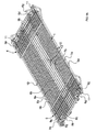
figure 3a est une vue en perspective de la forme d'exécution selon lafigure 1a , montrant la corbeille en position pliée ; - la
figure 3b est une vue en perspective d'une partie de la forme d'exécution selon lafigure 1a , montrant la corbeille en position pliée ; - la
figure 3c est une vue en coupe selon la ligne IIIc-IIIc de lafigure 3a ; - les
figures 4a et 4b sont des vues en perspective de l'élément de verrouillage selon une première forme d'exécution de l'invention; - la
figure 4c est une vue de dessus de l'élément de verrouillage desfigures 4a et 4b ; - la
figure 5 est une vue de dessus d'un élément de verrouillage selon une variante ; - la
figure 6a est une vue en perspective partielle d'un coin avant de la corbeille selon une deuxième forme d'exécution de l'invention; - la
figure 6b est une vue en perspective partielle d'un coin arrière de la corbeille selon la deuxième forme d'exécution de l'invention; - la
figure 7a est une vue en perspective d'un élément de verrouillage rapporté de la corbeille selon la deuxième forme d'exécution de l'invention; - la
figure 7b est une vue de dessus de l'élément de verrouillage de lafigure 7a ; - la
figure 8a est une vue en perspective d'une corbeille pliable selon une autre forme d'exécution de l'invention, représentée en position montée (prête à être utilisée) ; - la
figure 8b est une vue en perspective d'un côté de la corbeille de lafigure 8a ; - la
figure 9a est une vue en perspective de la forme d'exécution selon lafigure 8a , montrant deux corbeilles en position pliées et empilées; - la
figure 9b est une vue en perspective de la forme d'exécution selon lafigure 8a , montrant une corbeille en position pliée ; - la
figure 9c est une vue en perspective de la forme d'exécution selon lafigure 8a montrant la corbeille en cours de montage; et - la
figure 10 est une vue en perspective d'une corbeille pliable selon une variante de la corbeille de lafigure 8a .
- the
figure 1a is a perspective view of a collapsible basket according to one embodiment of the invention, shown in mounted position (ready to use); - the
figure 1b is a perspective view of the left side of the basket of thefigure 1 a with two locking elements according to a first embodiment; - the
figure 1c is a perspective view of a locking member mounted on the basket; - the
figure 1d is a top view of a locking element mounted on the basket; - the
figure 2a is a perspective view of the embodiment according to thefigure 1 showing the basket being erected; - the
figure 2b is a view of the embodiment according to thefigure 1 showing a side wall of the basket being assembled; - the
figure 3a is a perspective view of the embodiment according to thefigure 1a , showing the basket in the folded position; - the
figure 3b is a perspective view of a part of the embodiment according to thefigure 1a , showing the basket in the folded position; - the
figure 3c is a sectional view along line IIIc-IIIc of thefigure 3a ; - the
Figures 4a and 4b are perspective views of the locking member according to a first embodiment of the invention; - the
figure 4c is a top view of the locking element of theFigures 4a and 4b ; - the
figure 5 is a top view of a locking element according to a variant; - the
figure 6a is a partial perspective view of a front corner of the basket according to a second embodiment of the invention; - the
figure 6b is a partial perspective view of a rear corner of the basket according to the second embodiment of the invention; - the
figure 7a is a perspective view of a locking element attached to the basket according to the second embodiment of the invention; - the
figure 7b is a top view of the locking element of thefigure 7a ; - the
figure 8a is a perspective view of a collapsible basket according to another embodiment of the invention, shown in mounted position (ready to use); - the
figure 8b is a perspective view of one side of the basket of thefigure 8a ; - the
figure 9a is a perspective view of the embodiment according to thefigure 8a , showing two baskets in folded and stacked position; - the
figure 9b is a perspective view of the embodiment according to thefigure 8a , showing a basket in the folded position; - the
Figure 9c is a perspective view of the embodiment according to thefigure 8a showing the basket being assembled; and - the
figure 10 is a perspective view of a collapsible basket according to a variant of the basket of thefigure 8a .
Faisant référence aux figures, une corbeille pliable selon une forme d'exécution de l'invention comprend une paroi de fond 1, une paroi avant 2, une paroi arrière 3, et des parois latérales 4 et 5. Chacune des parois comprend un cadre métallique 6, 7, 8, 9 formé (dans la forme d'exécution illustrée) d'un fil métallique épais plié, et d'une grille formée d'un ensemble de fils métalliques 13, 14 s'étendant entre les bords du cadre.Referring to the figures, a collapsible basket according to one embodiment of the invention comprises a bottom wall 1, a
La paroi avant 2 est de plus faible hauteur que la paroi arrière 3, de façon à permettre l'accès aux produits contenus à l'intérieur de la corbeille, lorsqu'une corbeille identique est gerbée empilée sur celle-ci ou lorsque la corbeille est suspendue sous la paroi d'un rayon de présentation.The
Le cadre 9 de chaque paroi latérale 4, 5 a cinq côtés avec un côté arrière vertical 9a, un côté inférieur horizontal 9b dont la longueur correspond à la profondeur du fond 1, un côté supérieur horizontal 9e, un côté avant inférieur 9c incliné dont la hauteur est inférieure à celle du côté arrière 6, et un côté avant supérieur 9d incliné reliant entre elles une extrémité du côté supérieur 9e et celle du côté avant inférieur 9c. La hauteur du côté verticale 9a peut correspondre à celle de la paroi arrière 3 telle que illustré dans la variante de la
La paroi latérale 5 est symétrique à la paroi latérale 4 par rapport à un plan vertical médian.The
Le cadre de la paroi de fond 1 de la corbeille comporte, sur chacun de ses quatre côtés, des pivots 10, 11, qui sont dans la forme d'exécution illustrée, sous forme de cavaliers essentiellement en forme de U réalisés en fil métallique et dont les extrémités sont soudées au cadre. Il est également envisageable d'avoir des pivots sous forme d'anneaux en fil métallique ou en d'autres matériaux non soudés à un cadre et entourant les fils des cadres mutuellement pivotants. Dans les variantes des
Dans la variante de la
Les cadres 8, 7 des parois arrière 3 et avant 2 ont des parties latérales 8c, 8d ,7c, 7d s'étendant verticalement des extrémités des côtés supérieurs 8b, 7b (c'est-à-dire s'étendant orthogonalement aux côtés supérieurs 8b, 7b des cadres 8, 7), les parties latérales 8c, 8d, 7c, 7d servant comme support pour le montage des pièces de verrouillage 15. Les parties latérales ont une extrémité libre permettant aux pièces de verrouillage 15, 15', 15" de pouvoir être enfilées.The
Lorsque les parois arrière et avant sont pliées sous ou sur la paroi de fond en position démontée, les parties latérales 8c, 8d, 7c, 7d des cadres 8, 7 se trouvent parallèles et adjacentes aux côtés latéraux respectifs 6c, 6d de la paroi de fond 1.When the rear and front walls are folded under or on the bottom wall in the disassembled position, the
Le cadre 6 de la paroi de fond comprend en outre des éléments intermédiaires 6e, 6f parallèles aux côtés avant et arrière et soudés à leur extrémité aux côtés latéraux 6c, 6d du cadre. Les côtés latéraux avant et arrière 6a, 6b, 6c, 6d du cadre de la paroi de fond forment essentiellement un rectangle fermé rigide.The
Faisant référence notamment aux
Dans les variantes des
Dans les variantes des
Le cadre 8 de la paroi arrière 3 comprend aussi un élément intermédiaire 8e sous forme d'un fil métallique disposé essentiellement de façon parallèle aux côtés supérieurs et inférieurs 8a, 8d, et soudé au fil métallique 14 de la grille afin de rigidifier la grille celle-ci.The
Des éléments de guidage 16 sont disposés sur les parois latérales en saillie par rapport au côté supérieur 9e du cadre. Dans la forme d'exécution illustrée, les éléments de guidage sont sous forme de fils métalliques en U renversés, soudés au cadre sur le côté intérieur du cadre (en position montée). Les éléments de guidage 16 servent à positionner une corbeille placée sur une autre corbeille lors de l'empilement de plusieurs corbeilles. Le positionnement des éléments de guidage 16 est configuré de sorte à ce que l'élément de guidage s'enfile dans un coin formé par la jonction de deux éléments de cadre orthogonaux de la paroi de fond. Il y a de préférence deux éléments de guidage sur chaque paroi latérale, un élément de guidage arrière 16a et un élément de guidage avant 16b. Ainsi, les éléments de guidage arrière16a s'enfilent dans les coins 17a formés par l'élément du cadre intermédiaire arrière 6e soudé transversalement aux côtés des cadres 6d et 6c, et les éléments de guidage avant 16b s'enfilent dans les coins 17b formés par les jonctions des côtés latéraux 6c, 6d et du côté avant 6a.Guiding elements 16 are arranged on the side walls projecting from the
Les fils 14 des grilles des parois avant et arrière sont soudés aux cadres 7,8 sur leurs faces intérieures (lorsque la corbeille est en position montée). Les fils 13 de la grille de la paroi de fond 1 sont également soudés sur le cadre de la paroi de fond sur sa face supérieure, c'est-à-dire sur la face intérieure de la corbeille lorsque la corbeille est en position montée. Lorsque les parois avant et arrière sont repliées (c'est-à-dire en position démontée) contre la face inférieure de la paroi de fond, les fils 14 des grilles des parois avant 2 et arrière 3 sont éloignés des fils 13 de la grille de la paroi de fond 1. Les côtés extérieurs des cadres 8 et 7 des parois arrière 3 et avant 2 se trouvent positionnés contre les fils 13 de la grille de la paroi de fond. Dans cette position démontée, les éléments 8a, 8b du cadre 8 de la paroi arrière sont essentiellement dans le même plan que les éléments 6a, 6b, 6e, 6f du cadre de la paroi de fond, réduisant ainsi le volume des parois pliées ainsi que le jeu nécessaire pour permettre le pivotement des parois. Les éléments 7b, 7a, 7c, 7d du cadre de la paroi avant 2 sont disposés également essentiellement dans le même plan que le cadre de la paroi de fond en position démontée.The
Les côtés supérieurs 8b et inférieurs 8a du cadre arrière 8 sont un peu plus courts que le côté arrière 6b du cadre 6 de la paroi de fond 1 de manière à permettre au cadre 8 de la paroi arrière de s'insérer dans le périmètre du cadre 6 de la paroi de fond. De même, les côtés supérieurs 7b et 7a du cadre 7 de la paroi avant 2 sont légèrement plus courts que le côté avant 6a du cadre 6 de la paroi du fond 1. Les parois latérales 4, 5 sont quant à elles repliées sur la face supérieure de la paroi de fond 1 en position démontée.The
La configuration décrite ci-dessus permet aux pivots avant et arrière 10 (les cavaliers en U orientés horizontalement) d'avoir un jeu tout juste suffisant pour permettre la rotation des côtés 7a, 8a des cadres avant 7 et arrière 8, sans nécessiter de jeu supplémentaire. Le jeu des pivots 11 sur les côtés latéraux 6c, 6d peut également être réduit au jeu nécessaire pour plier les parois latérales 4, 5 sur la face supérieure de la paroi de fond 1, sans jeu supplémentaire nécessaire pour le verrouillage ou pour accommoder les parois avant et arrière. Ce jeu réduit des pivots permet de réaliser une corbeille plus stable, rigide et moins bruyante à l'utilisation que les corbeilles pliables conventionnelles. La pièce de verrouillage rapportée 15 permet en plus d'éliminer le jeu entre les parois avant, arrière et latérales lors du verrouillage des parois en position montée telles qu'illustrées dans la
L'élément de verrouillage 15, 15', 15" comprend une première partie de fixation 17, 17' destinée à être montée sur le cadre d'une paroi et une deuxième partie de fixation 18, 18' destinée à être fixée au cadre de la paroi adjacente, les deux parties de fixation étant reliées solidairement ensemble. L'élément de verrouillage 15, 15', 15" peut avantageusement être formé d'une pièce en matière plastique, de préférence en matière plastique injectée thermodurcissable.The locking
Chaque partie de fixation 17, 17', 18, 18' comprend un canal 19, 20 pour loger des portions de cadres respectifs. La deuxième partie de fixation 18 comprend des bras élastiques 21 configurés pour pincer élastiquement le fil du cadre, les extrémités libres 22 des bras élastiques formant un « V » pour écarter les bras et guider la portion du fil du cadre dans le canal 20. La deuxième partie de fixation permet donc l'insertion de la portion de cadre dans le canal dans une direction orthogonale à l'axe A2 du canal.Each
La première partie de fixation 17 est configurée pour être enfilée sur une portion du cadre dans la direction de l'axe central A1 du canal 19, notamment sur les parties latérales 8c, 8d ,7c, 7d des cadres 8, 7 des parois arrière 3 et avant 2. Dans une forme d'exécution (
Dans une forme d'exécution préférée, les parois respectives formant les bras 21, 24 sont configurées pour que la force élastique de serrement des bras 24 de la première partie de fixation sur le fil du cadre soit supérieure à la force élastique de serrement des bras 21 de la deuxième partie de fixation sur le fil du cadre. Dans le cadre de l'invention, il est également possible que la paroi de la première partie de fixation 17, 17' soit fermée. Pour faciliter l'insertion de la première partie de fixation 17 sur le fil du cadre, le côté supérieur 30 du canal 19 peut avoir une forme évasée, par exemple une forme d'entonnoir.In a preferred embodiment, the respective walls forming the
Dans une forme d'exécution, la surface intérieure de la paroi du canal 19 de la première partie de fixation 17 comprend des protubérances 25 destinées à être écrasées contre le fil du cadre après enfilement, afin d'augmenter la force de frottement entre la partie de fixation et la portion de cadre, cela pour mieux résister au déplacement de l'élément de verrouillage en rotation et dans la direction axiale A1 sur le fil du cadre. Les protubérances 25 sont en saillie par rapport à la surface intérieure 26 de la paroi formant le canal 19 venant en appui élastique contre la portion de cadre. Dans la forme d'exécution illustrée à la
Il est également possible d'avoir des protubérances avec des autres formes, par exemple des protubérances discrètes non prismatiques réparties sur la surface intérieure 26.It is also possible to have protuberances with other shapes, for example discrete nonprismatic protuberances distributed on the
La première partie de fixation peut comprendre en outre des éléments anti-rotation 28, 29 sous forme d'extensions destinées à être positionnées de part et d'autre d'une portion de cadre transversale à la portion de cadre sur laquelle la partie de fixation est enfilée comme illustré dans la
L'utilisation de la corbeille pliable selon l'invention est alors la suivante. La corbeille étant dans sa position démontée représentée à la
On peut ensuite procéder à la fixation des parois latérales 4, 5 aux parois arrière 3 et avant 2 en poussant leurs cadres dans les parties de fixation élastiques 18 des éléments de verrouillage 15. La corbeille peut aussi être facilement pliée en tirant sur les parois latérales pour dégager les cadres des parties de fixation 18 des éléments de verrouillage 15.The
Faisant référence notamment aux
Chaque partie de fixation 17', 18' comprend un canal 19', 20 pour loger des portions de cadres respectifs. La deuxième partie de fixation 18' comprend des bras élastiques 21 a et 21 b configurés pour pincer élastiquement le fil du cadre, les extrémités libres 22 des bras élastiques formant un « V » pour écarter les bras et guider la portion du fil du cadre dans le canal 20. La deuxième partie de fixation permet donc l'insertion de la portion de cadre dans le canal dans une direction orthogonale à l'axe A2 du canal.Each attachment portion 17 ', 18' includes a
La première partie de fixation 17' est configurée pour être enfilée sur une portion du cadre dans la direction de l'axe central A1 du canal 19', notamment sur les parties latérales 8c, 8d ,7c, 7d des cadres 8, 7 des parois arrière 3 et avant 2. Pour faciliter l'insertion de la première partie de fixation 17' sur le fil du cadre, le côté supérieur 30 du canal 19' peut avoir une forme évasée, par exemple une forme d'entonnoir.The first fixing portion 17 'is configured to be threaded onto a portion of the frame in the direction of the central axis A1 of the channel 19', in particular on the
La surface intérieure de la paroi du canal 19' de la première partie de fixation 17' peut comprendre des protubérances 25' destinées à être écrasées contre le fil du cadre après enfilement, afin d'augmenter la force de frottement entre la partie de fixation et la portion de cadre, cela pour mieux résister au déplacement de l'élément de verrouillage dans la direction axiale A1 sur le fil du cadre. Les protubérances 25' sont en saillie par rapport à la surface intérieure 26' de la paroi formant le canal 19' venant en appui contre la portion de cadre. Il est également possible d'avoir des protubérances avec des autres formes, par exemple des protubérances discrètes non prismatiques réparties sur la surface intérieure 26'. Il est également possible d'avoir une surface lisse sans aucune protubérance dans le canal 19' dans cette forme d'exécution, notamment en raison de la présence de l'élément anti-rotation 28'.The inner surface of the wall of the channel 19 'of the first fixing portion 17' may comprise protuberances 25 'intended to be crushed against the wire of the frame after threading, in order to increase the friction force between the fixing portion and the frame portion, that to better withstand the displacement of the locking element in the axial direction A1 on the frame wire. The protuberances 25 'protrude from the inner surface 26' of the wall forming the channel 19 'bearing against the frame portion. It is also possible to have protuberances with other shapes, for example discrete nonprismatic protuberances distributed on the inner surface 26 '. It is also possible to have a smooth surface without any protrusion in the channel 19 'in this embodiment, in particular because of the presence of the anti-rotation element 28'.
L'élément anti-rotation 28' comprend une troisième partie de fixation 31 destiné à être montée sur la grille adjacente du cadre 8c, 8d, 7c, 7d, et est relié solidairement à l'élément 17' par des bras 32a, 32b. Le bras 32a, 32b comprend de préférence une certaine élasticité. La troisième partie de fixation 31 comprend des bras élastiques 33a, 33b configurés pour pincer élastiquement un fil de la grille, les bras élastiques 33a, 33b ayant la forme d'un « C » avec un canal 35 logeant le fil de la grille La troisième partie de fixation empêche la rotation de l'élément de verouillage 15' sur l'axe A1 du cadre 7c, 7d, 8c, 8d.The anti-rotation element 28 'comprises a
Les première et deuxième parties de fixation 17', 18' peuvent comprendre en outre une paroi de liaison 35, 35a, 35b sur un côté (voir
Claims (13)
- Foldable metal wire basket comprising a bottom wall (1), two side walls (4, 5), a back wall (3), a front wall (2) and fastening means to lock the side walls to the front and back walls in mounted position, each of the walls comprising a metal wire frame and gridding, the front, back and side walls being pivot-mounted on the bottom wall, the frame (6) of the bottom wall (1) being inseparably attached on each of its four sides via pivots (10, 11) onto the frames (7, 8, 9) of the side and front walls, the attaching means comprising added-on locking parts (15), each of the locking parts comprising a first fastening part (17) and a second fastening part (18), the first fastening part comprising a channel (19) intended to be inserted over a portion of frame (7c, 7d, 8c, 8d) of a wall and anti-rotation means (28, 28'), and the second fastening part (18) comprising elastic arms (21) configured to elastically grip a portion of the frame wire of the adjacent wall, the two fastening parts being secured together, the said basket being characterized in that the anti-rotation means comprise either extensions (28) generally extending in the direction of the axis (A1) of the channel (19) and protruding from an upper end (30) of the channel (19), or an extension (28') secured to the first fastening part (17') and having a third fastening part (31) intended to be attached onto a wire of the gridding (14) of the back and front walls (2, 3).
- The foldable basket according to claim 1, characterized in that the locking part is an injected part in thermosetting plastic material.
- The foldable basket according to claim 1 or 2, characterized in that an inner surface of one wall forming the channel (19) of the first fastening part (17) comprises protuberances (25) configured to be flattened when mounting on a portion of frame (7c, 7d, 8c, 8d).
- The basket according to claim 5 characterized in that the extension (28') is secured to the first fastening part (17') via arms (32a, 32b) having some elasticity.
- The basket according to claim 5 or 6 characterized in that the third fastening part (31) comprises elastic arms (33a, 33b) configured elastically to grip a gridding wire.
- The basket according to one of the preceding claims, characterized in that the basket comprises foolproof elements (6g) on side walls formed by a section of crosswire (6c) of the bottom wall, these extending vertically, offset from a bottom wire (9b) of the side wall (4, 5).
- The foldable basket according to claim 8, characterized in that the foolproof elements (6g) also extend laterally, offset from the side wall (4, 5).
- The foldable basket according to claim 8 or 9, characterized in that the offset section of crosswire (6g) has a space for housing locking parts (15, 15', 15") in folded-down position.
- The foldable basket according to claim 8, characterized in that the wires (9b) of the frames of the side walls (4, 5) comprise a corresponding offset (9g) to conform to the shape of the vertical continuation of the wire of the bottom wall.
- The foldable basket according to the preceding claim, characterized in that the foolproof elements (6g) are of flared, inverted V-shape to allow stable stacking with defined positioning of the folded baskets.
- The foldable basket according to one of the two preceding claims, characterized in that the corresponding offsets (9g) of the frames of the side walls comprise a section of gridding crosswire (38) on a side configured to interfere with the foolproof element (6g) to stop rotation of the side wall in mounted position.
- The foldable basket according to one of the preceding claims, characterized in that the frame (6) of the bottom wall (1) on each of its four sides comprises pivots (10, 11) in the form of U-shaped tabs in metal wire whose ends are welded to the frame, the tabs (10) on the front (6a) and back (6b) sides of the frame extending in a direction parallel to the bottom wall, and the tabs (11) on the side walls (6c, 6d) of the frame extending in a direction orthogonal to the bottom wall, the gridding wires (14) of the front (2) and back (3) walls being welded onto the frames (7, 8) on their inner surfaces, and gridding wires (13) of the bottom wall (1) being welded onto the frame of the bottom wall on its upper surface, the front and back walls being configured to be folded over the underside of the bottom wall and the side walls being configured to be folded over the upper surface of the bottom wall.
- The foldable basket according to the preceding claim, characterized in that the upper side (8b) of the frame (8) of the back wall is slightly shorter than the back side (6b) of the frame (6) of the bottom wall to enable the frame of the back wall to be inserted within the perimeter of the frame of the bottom wall, and in that the upper side (7b) of the frame (7) of the front wall (2) is slightly shorter than the front side (6a) of the frame (6) of the bottom wall to enable the frame of the front wall to be inserted within the perimeter of the frame of the bottom wall.
Priority Applications (1)
| Application Number | Priority Date | Filing Date | Title |
|---|---|---|---|
| PL10787902T PL2496487T3 (en) | 2009-11-07 | 2010-11-07 | Collapsible basket made of metal wire |
Applications Claiming Priority (2)
| Application Number | Priority Date | Filing Date | Title |
|---|---|---|---|
| CH01721/09A CH702149B1 (en) | 2009-11-07 | 2009-11-07 | collapsible wire basket. |
| PCT/IB2010/055051 WO2011055345A2 (en) | 2009-11-07 | 2010-11-07 | Collapsible basket made of metal wire |
Publications (2)
| Publication Number | Publication Date |
|---|---|
| EP2496487A2 EP2496487A2 (en) | 2012-09-12 |
| EP2496487B1 true EP2496487B1 (en) | 2014-10-08 |
Family
ID=43446880
Family Applications (1)
| Application Number | Title | Priority Date | Filing Date |
|---|---|---|---|
| EP10787902.5A Active EP2496487B1 (en) | 2009-11-07 | 2010-11-07 | Collapsible basket made of metal wire |
Country Status (6)
| Country | Link |
|---|---|
| EP (1) | EP2496487B1 (en) |
| CH (1) | CH702149B1 (en) |
| ES (1) | ES2525746T3 (en) |
| FR (2) | FR2952355B1 (en) |
| PL (1) | PL2496487T3 (en) |
| WO (1) | WO2011055345A2 (en) |
Families Citing this family (3)
| Publication number | Priority date | Publication date | Assignee | Title |
|---|---|---|---|---|
| CN102715764A (en) * | 2012-06-01 | 2012-10-10 | 戴文军 | Folding type moveable folded cage |
| CN102908081A (en) * | 2012-11-19 | 2013-02-06 | 雅鼎卫浴股份有限公司 | Folding type wall-hung basket for bathroom |
| US20170129652A1 (en) * | 2015-09-14 | 2017-05-11 | Ifco Systems Gmbh | Container assembly with promotional panels and associated methods for making the same |
Family Cites Families (9)
| Publication number | Priority date | Publication date | Assignee | Title |
|---|---|---|---|---|
| US3349939A (en) * | 1964-05-18 | 1967-10-31 | Union Steel Prod Co | Portable and collapsible stacking bins or crates |
| US3726415A (en) * | 1971-11-03 | 1973-04-10 | J Malik | Wire rack |
| DE7813374U1 (en) * | 1978-05-02 | 1978-09-07 | Fuhrmeister Winfried | Goods basket with mesh walls |
| GB9508454D0 (en) * | 1995-04-26 | 1995-06-14 | Tenby Ind Ltd | Clamping of electrical or other cable |
| GB2314833A (en) * | 1996-07-02 | 1998-01-14 | Heartbeat Manufacturing Co The | Containers |
| US6192834B1 (en) * | 1999-02-10 | 2001-02-27 | Doskocil Manufacturing Company, Inc. | Collapsible cage |
| NL1020042C2 (en) * | 2002-02-22 | 2003-08-27 | Vika Metaal B V | Collapsible container, has front wall sloping away from base and back and side walls extending perpendicular to base |
| US6691382B1 (en) * | 2002-10-08 | 2004-02-17 | Lien-Cheng Su | Retainer adapted to detachably secure two wired/grilled members together |
| FR2850953B1 (en) * | 2003-02-06 | 2006-08-04 | Goupil Ind | FOLDING BASKET FOR THE PRESENTATION OF OBJECTS FOR SALE |
-
2009
- 2009-11-07 CH CH01721/09A patent/CH702149B1/en not_active IP Right Cessation
-
2010
- 2010-11-04 FR FR1059108A patent/FR2952355B1/en active Active
- 2010-11-04 FR FR1059106A patent/FR2952354A1/en active Pending
- 2010-11-07 EP EP10787902.5A patent/EP2496487B1/en active Active
- 2010-11-07 PL PL10787902T patent/PL2496487T3/en unknown
- 2010-11-07 WO PCT/IB2010/055051 patent/WO2011055345A2/en active Application Filing
- 2010-11-07 ES ES10787902.5T patent/ES2525746T3/en active Active
Also Published As
| Publication number | Publication date |
|---|---|
| PL2496487T3 (en) | 2015-04-30 |
| CH702149B1 (en) | 2014-06-30 |
| FR2952355A1 (en) | 2011-05-13 |
| EP2496487A2 (en) | 2012-09-12 |
| ES2525746T3 (en) | 2014-12-29 |
| WO2011055345A2 (en) | 2011-05-12 |
| CH702149A1 (en) | 2011-05-13 |
| FR2952354A1 (en) | 2011-05-13 |
| FR2952355B1 (en) | 2015-09-18 |
| WO2011055345A3 (en) | 2011-06-30 |
Similar Documents
| Publication | Publication Date | Title |
|---|---|---|
| FR2530443A1 (en) | CONSOLE DISPLAY FOR SOCKET WRENCHES OR THE LIKE TOOLS AND PACKAGE INCLUDING THE DISPLAY | |
| FR2751723A1 (en) | ASSEMBLY ASSEMBLY FOR CABLE PATHWAY STONES AND CABLE CHAIN STONES | |
| EP2496487B1 (en) | Collapsible basket made of metal wire | |
| FR2946510A1 (en) | School table for use in classroom, has fixing unit comprising stud that is received in reception housing so that walls of stud are in surface contact with walls of housing, where fixing unit fixes table top support on leg assembly | |
| EP0619239A1 (en) | Container provided with a one-piece catch | |
| EP1876928B1 (en) | Tripod slat end piece with a highly stabilised range of movement | |
| FR2556321A1 (en) | Stackable container for storage and transport made of synthetic material | |
| LU85275A1 (en) | SYSTEM FOR DELIVERY / PRESENTATION OF ITEMS | |
| EP0261008B1 (en) | Removable hinge, especially for a fishermen's seat box | |
| EP1257458B1 (en) | Trolley basket for self-service shop | |
| FR2767260A3 (en) | Device for dishwasher basket for holding items to be washed, esp. in domestic dishwasher strut of basket with guide groove in which folding yoke can at least partially latch to lock holder and from which it can be released to move holder | |
| EP1029469A1 (en) | Bottle rack and metallic component | |
| EP0857448B1 (en) | Grill grid consisting of hinged sections | |
| FR2693984A1 (en) | Dismantlable storage tray - has bottom, rear and front walls formed from single flexible angled piece with clip on identical rigid side walls | |
| FR2700724A1 (en) | Case for a series of tools, particularly Allen keys | |
| FR2661656A1 (en) | Pallet box | |
| EP1454833B1 (en) | collapsible basket for the display of goods | |
| FR2755103A1 (en) | Bio-degradable pallet crate usable for displaying merchandise | |
| EP1449785A1 (en) | Fastening device for a plastic lid on a plastic box for vacuum preservation of articles in a bulk arrangement in the box | |
| FR2675672A1 (en) | DRAWER IN SHEET. | |
| FR3072262A1 (en) | KITCHEN ARTICLE | |
| EP1554923B1 (en) | Support for plants, especially adaptable on polygonal plant pots | |
| FR2861967A1 (en) | Support rack for use in e.g. transport trolley, has notches made in vertical wall and descending between opening and blocking ends, where each notch has end that opens on one edge of wall and blocking end | |
| EP1772076B1 (en) | Sidestop device for mattresses | |
| FR2730614A1 (en) | ANTI-TILTING DRAWER CABINET |
Legal Events
| Date | Code | Title | Description |
|---|---|---|---|
| PUAI | Public reference made under article 153(3) epc to a published international application that has entered the european phase |
Free format text: ORIGINAL CODE: 0009012 |
|
| 17P | Request for examination filed |
Effective date: 20120601 |
|
| AK | Designated contracting states |
Kind code of ref document: A2 Designated state(s): AL AT BE BG CH CY CZ DE DK EE ES FI FR GB GR HR HU IE IS IT LI LT LU LV MC MK MT NL NO PL PT RO RS SE SI SK SM TR |
|
| DAX | Request for extension of the european patent (deleted) | ||
| REG | Reference to a national code |
Ref country code: DE Ref legal event code: R079 Ref document number: 602010019453 Country of ref document: DE Free format text: PREVIOUS MAIN CLASS: B65D0021020000 Ipc: B65D0006260000 |
|
| GRAP | Despatch of communication of intention to grant a patent |
Free format text: ORIGINAL CODE: EPIDOSNIGR1 |
|
| RIC1 | Information provided on ipc code assigned before grant |
Ipc: B65D 6/08 20060101ALI20140319BHEP Ipc: B65D 6/26 20060101AFI20140319BHEP Ipc: B65D 21/02 20060101ALI20140319BHEP Ipc: A47B 55/02 20060101ALN20140319BHEP |
|
| INTG | Intention to grant announced |
Effective date: 20140417 |
|
| GRAS | Grant fee paid |
Free format text: ORIGINAL CODE: EPIDOSNIGR3 |
|
| RBV | Designated contracting states (corrected) |
Designated state(s): AL AT BE BG CY CZ DE DK EE ES FI FR GB GR HR HU IE IS IT LT LU LV MC MK MT NL NO PL PT RO RS SE SI SK SM TR |
|
| GRAA | (expected) grant |
Free format text: ORIGINAL CODE: 0009210 |
|
| AK | Designated contracting states |
Kind code of ref document: B1 Designated state(s): AL AT BE BG CY CZ DE DK EE ES FI FR GB GR HR HU IE IS IT LT LU LV MC MK MT NL NO PL PT RO RS SE SI SK SM TR |
|
| REG | Reference to a national code |
Ref country code: GB Ref legal event code: FG4D Free format text: NOT ENGLISH |
|
| REG | Reference to a national code |
Ref country code: AT Ref legal event code: REF Ref document number: 690435 Country of ref document: AT Kind code of ref document: T Effective date: 20141015 |
|
| REG | Reference to a national code |
Ref country code: IE Ref legal event code: FG4D Free format text: LANGUAGE OF EP DOCUMENT: FRENCH |
|
| REG | Reference to a national code |
Ref country code: DE Ref legal event code: R096 Ref document number: 602010019453 Country of ref document: DE Effective date: 20141120 |
|
| REG | Reference to a national code |
Ref country code: RO Ref legal event code: EPE |
|
| REG | Reference to a national code |
Ref country code: ES Ref legal event code: FG2A Ref document number: 2525746 Country of ref document: ES Kind code of ref document: T3 Effective date: 20141229 |
|
| REG | Reference to a national code |
Ref country code: NL Ref legal event code: VDEP Effective date: 20141008 |
|
| REG | Reference to a national code |
Ref country code: AT Ref legal event code: MK05 Ref document number: 690435 Country of ref document: AT Kind code of ref document: T Effective date: 20141008 |
|
| REG | Reference to a national code |
Ref country code: LT Ref legal event code: MG4D |
|
| PG25 | Lapsed in a contracting state [announced via postgrant information from national office to epo] |
Ref country code: NL Free format text: LAPSE BECAUSE OF FAILURE TO SUBMIT A TRANSLATION OF THE DESCRIPTION OR TO PAY THE FEE WITHIN THE PRESCRIBED TIME-LIMIT Effective date: 20141008 |
|
| PG25 | Lapsed in a contracting state [announced via postgrant information from national office to epo] |
Ref country code: IS Free format text: LAPSE BECAUSE OF FAILURE TO SUBMIT A TRANSLATION OF THE DESCRIPTION OR TO PAY THE FEE WITHIN THE PRESCRIBED TIME-LIMIT Effective date: 20150208 Ref country code: LT Free format text: LAPSE BECAUSE OF FAILURE TO SUBMIT A TRANSLATION OF THE DESCRIPTION OR TO PAY THE FEE WITHIN THE PRESCRIBED TIME-LIMIT Effective date: 20141008 Ref country code: NO Free format text: LAPSE BECAUSE OF FAILURE TO SUBMIT A TRANSLATION OF THE DESCRIPTION OR TO PAY THE FEE WITHIN THE PRESCRIBED TIME-LIMIT Effective date: 20150108 Ref country code: FI Free format text: LAPSE BECAUSE OF FAILURE TO SUBMIT A TRANSLATION OF THE DESCRIPTION OR TO PAY THE FEE WITHIN THE PRESCRIBED TIME-LIMIT Effective date: 20141008 Ref country code: PT Free format text: LAPSE BECAUSE OF FAILURE TO SUBMIT A TRANSLATION OF THE DESCRIPTION OR TO PAY THE FEE WITHIN THE PRESCRIBED TIME-LIMIT Effective date: 20150209 |
|
| REG | Reference to a national code |
Ref country code: PL Ref legal event code: T3 |
|
| PG25 | Lapsed in a contracting state [announced via postgrant information from national office to epo] |
Ref country code: RS Free format text: LAPSE BECAUSE OF FAILURE TO SUBMIT A TRANSLATION OF THE DESCRIPTION OR TO PAY THE FEE WITHIN THE PRESCRIBED TIME-LIMIT Effective date: 20141008 Ref country code: HR Free format text: LAPSE BECAUSE OF FAILURE TO SUBMIT A TRANSLATION OF THE DESCRIPTION OR TO PAY THE FEE WITHIN THE PRESCRIBED TIME-LIMIT Effective date: 20141008 Ref country code: AT Free format text: LAPSE BECAUSE OF FAILURE TO SUBMIT A TRANSLATION OF THE DESCRIPTION OR TO PAY THE FEE WITHIN THE PRESCRIBED TIME-LIMIT Effective date: 20141008 Ref country code: GR Free format text: LAPSE BECAUSE OF FAILURE TO SUBMIT A TRANSLATION OF THE DESCRIPTION OR TO PAY THE FEE WITHIN THE PRESCRIBED TIME-LIMIT Effective date: 20150109 Ref country code: CY Free format text: LAPSE BECAUSE OF FAILURE TO SUBMIT A TRANSLATION OF THE DESCRIPTION OR TO PAY THE FEE WITHIN THE PRESCRIBED TIME-LIMIT Effective date: 20141008 Ref country code: LV Free format text: LAPSE BECAUSE OF FAILURE TO SUBMIT A TRANSLATION OF THE DESCRIPTION OR TO PAY THE FEE WITHIN THE PRESCRIBED TIME-LIMIT Effective date: 20141008 Ref country code: SE Free format text: LAPSE BECAUSE OF FAILURE TO SUBMIT A TRANSLATION OF THE DESCRIPTION OR TO PAY THE FEE WITHIN THE PRESCRIBED TIME-LIMIT Effective date: 20141008 |
|
| REG | Reference to a national code |
Ref country code: DE Ref legal event code: R119 Ref document number: 602010019453 Country of ref document: DE |
|
| PG25 | Lapsed in a contracting state [announced via postgrant information from national office to epo] |
Ref country code: BE Free format text: LAPSE BECAUSE OF NON-PAYMENT OF DUE FEES Effective date: 20141130 |
|
| PG25 | Lapsed in a contracting state [announced via postgrant information from national office to epo] |
Ref country code: CZ Free format text: LAPSE BECAUSE OF FAILURE TO SUBMIT A TRANSLATION OF THE DESCRIPTION OR TO PAY THE FEE WITHIN THE PRESCRIBED TIME-LIMIT Effective date: 20141008 Ref country code: EE Free format text: LAPSE BECAUSE OF FAILURE TO SUBMIT A TRANSLATION OF THE DESCRIPTION OR TO PAY THE FEE WITHIN THE PRESCRIBED TIME-LIMIT Effective date: 20141008 Ref country code: MC Free format text: LAPSE BECAUSE OF FAILURE TO SUBMIT A TRANSLATION OF THE DESCRIPTION OR TO PAY THE FEE WITHIN THE PRESCRIBED TIME-LIMIT Effective date: 20141008 Ref country code: DK Free format text: LAPSE BECAUSE OF FAILURE TO SUBMIT A TRANSLATION OF THE DESCRIPTION OR TO PAY THE FEE WITHIN THE PRESCRIBED TIME-LIMIT Effective date: 20141008 Ref country code: SK Free format text: LAPSE BECAUSE OF FAILURE TO SUBMIT A TRANSLATION OF THE DESCRIPTION OR TO PAY THE FEE WITHIN THE PRESCRIBED TIME-LIMIT Effective date: 20141008 |
|
| PLBE | No opposition filed within time limit |
Free format text: ORIGINAL CODE: 0009261 |
|
| STAA | Information on the status of an ep patent application or granted ep patent |
Free format text: STATUS: NO OPPOSITION FILED WITHIN TIME LIMIT |
|
| REG | Reference to a national code |
Ref country code: IE Ref legal event code: MM4A |
|
| 26N | No opposition filed |
Effective date: 20150709 |
|
| GBPC | Gb: european patent ceased through non-payment of renewal fee |
Effective date: 20150108 |
|
| PG25 | Lapsed in a contracting state [announced via postgrant information from national office to epo] |
Ref country code: GB Free format text: LAPSE BECAUSE OF NON-PAYMENT OF DUE FEES Effective date: 20150108 Ref country code: IE Free format text: LAPSE BECAUSE OF NON-PAYMENT OF DUE FEES Effective date: 20141107 Ref country code: DE Free format text: LAPSE BECAUSE OF NON-PAYMENT OF DUE FEES Effective date: 20150602 |
|
| REG | Reference to a national code |
Ref country code: FR Ref legal event code: PLFP Year of fee payment: 6 |
|
| PG25 | Lapsed in a contracting state [announced via postgrant information from national office to epo] |
Ref country code: SI Free format text: LAPSE BECAUSE OF FAILURE TO SUBMIT A TRANSLATION OF THE DESCRIPTION OR TO PAY THE FEE WITHIN THE PRESCRIBED TIME-LIMIT Effective date: 20141008 |
|
| PG25 | Lapsed in a contracting state [announced via postgrant information from national office to epo] |
Ref country code: SM Free format text: LAPSE BECAUSE OF FAILURE TO SUBMIT A TRANSLATION OF THE DESCRIPTION OR TO PAY THE FEE WITHIN THE PRESCRIBED TIME-LIMIT Effective date: 20141008 |
|
| PG25 | Lapsed in a contracting state [announced via postgrant information from national office to epo] |
Ref country code: BG Free format text: LAPSE BECAUSE OF FAILURE TO SUBMIT A TRANSLATION OF THE DESCRIPTION OR TO PAY THE FEE WITHIN THE PRESCRIBED TIME-LIMIT Effective date: 20141008 |
|
| PG25 | Lapsed in a contracting state [announced via postgrant information from national office to epo] |
Ref country code: MT Free format text: LAPSE BECAUSE OF FAILURE TO SUBMIT A TRANSLATION OF THE DESCRIPTION OR TO PAY THE FEE WITHIN THE PRESCRIBED TIME-LIMIT Effective date: 20141008 Ref country code: HU Free format text: LAPSE BECAUSE OF FAILURE TO SUBMIT A TRANSLATION OF THE DESCRIPTION OR TO PAY THE FEE WITHIN THE PRESCRIBED TIME-LIMIT; INVALID AB INITIO Effective date: 20101107 Ref country code: LU Free format text: LAPSE BECAUSE OF NON-PAYMENT OF DUE FEES Effective date: 20141107 Ref country code: TR Free format text: LAPSE BECAUSE OF FAILURE TO SUBMIT A TRANSLATION OF THE DESCRIPTION OR TO PAY THE FEE WITHIN THE PRESCRIBED TIME-LIMIT Effective date: 20141008 |
|
| REG | Reference to a national code |
Ref country code: FR Ref legal event code: PLFP Year of fee payment: 7 |
|
| REG | Reference to a national code |
Ref country code: FR Ref legal event code: PLFP Year of fee payment: 8 |
|
| PGFP | Annual fee paid to national office [announced via postgrant information from national office to epo] |
Ref country code: RO Payment date: 20171031 Year of fee payment: 8 |
|
| PGFP | Annual fee paid to national office [announced via postgrant information from national office to epo] |
Ref country code: PL Payment date: 20171024 Year of fee payment: 8 |
|
| PG25 | Lapsed in a contracting state [announced via postgrant information from national office to epo] |
Ref country code: MK Free format text: LAPSE BECAUSE OF FAILURE TO SUBMIT A TRANSLATION OF THE DESCRIPTION OR TO PAY THE FEE WITHIN THE PRESCRIBED TIME-LIMIT Effective date: 20141008 |
|
| PG25 | Lapsed in a contracting state [announced via postgrant information from national office to epo] |
Ref country code: AL Free format text: LAPSE BECAUSE OF FAILURE TO SUBMIT A TRANSLATION OF THE DESCRIPTION OR TO PAY THE FEE WITHIN THE PRESCRIBED TIME-LIMIT Effective date: 20141008 |
|
| PG25 | Lapsed in a contracting state [announced via postgrant information from national office to epo] |
Ref country code: RO Free format text: LAPSE BECAUSE OF NON-PAYMENT OF DUE FEES Effective date: 20181107 |
|
| PG25 | Lapsed in a contracting state [announced via postgrant information from national office to epo] |
Ref country code: PL Free format text: LAPSE BECAUSE OF NON-PAYMENT OF DUE FEES Effective date: 20181107 |
|
| PGFP | Annual fee paid to national office [announced via postgrant information from national office to epo] |
Ref country code: ES Payment date: 20220121 Year of fee payment: 12 |
|
| P01 | Opt-out of the competence of the unified patent court (upc) registered |
Effective date: 20230613 |
|
| REG | Reference to a national code |
Ref country code: ES Ref legal event code: FD2A Effective date: 20231229 |
|
| PG25 | Lapsed in a contracting state [announced via postgrant information from national office to epo] |
Ref country code: ES Free format text: LAPSE BECAUSE OF NON-PAYMENT OF DUE FEES Effective date: 20221108 |
|
| PG25 | Lapsed in a contracting state [announced via postgrant information from national office to epo] |
Ref country code: ES Free format text: LAPSE BECAUSE OF NON-PAYMENT OF DUE FEES Effective date: 20221108 |
|
| PGFP | Annual fee paid to national office [announced via postgrant information from national office to epo] |
Ref country code: IT Payment date: 20231124 Year of fee payment: 14 Ref country code: FR Payment date: 20231120 Year of fee payment: 14 |