EP2496481B1 - Multi-speed resin cartridge production system - Google Patents
Multi-speed resin cartridge production system Download PDFInfo
- Publication number
- EP2496481B1 EP2496481B1 EP20100829148 EP10829148A EP2496481B1 EP 2496481 B1 EP2496481 B1 EP 2496481B1 EP 20100829148 EP20100829148 EP 20100829148 EP 10829148 A EP10829148 A EP 10829148A EP 2496481 B1 EP2496481 B1 EP 2496481B1
- Authority
- EP
- European Patent Office
- Prior art keywords
- base material
- resin
- branch lines
- valve arrangement
- valve
- Prior art date
- Legal status (The legal status is an assumption and is not a legal conclusion. Google has not performed a legal analysis and makes no representation as to the accuracy of the status listed.)
- Active
Links
Images

Classifications
-
- E—FIXED CONSTRUCTIONS
- E21—EARTH OR ROCK DRILLING; MINING
- E21D—SHAFTS; TUNNELS; GALLERIES; LARGE UNDERGROUND CHAMBERS
- E21D20/00—Setting anchoring-bolts
- E21D20/02—Setting anchoring-bolts with provisions for grouting
- E21D20/025—Grouting with organic components, e.g. resin
- E21D20/026—Cartridges; Grouting charges
-
- B—PERFORMING OPERATIONS; TRANSPORTING
- B65—CONVEYING; PACKING; STORING; HANDLING THIN OR FILAMENTARY MATERIAL
- B65B—MACHINES, APPARATUS OR DEVICES FOR, OR METHODS OF, PACKAGING ARTICLES OR MATERIALS; UNPACKING
- B65B29/00—Packaging of materials presenting special problems
- B65B29/10—Packaging two or more different substances isolated from one another in the package but capable of being mixed without opening the package, e.g. forming packages containing a resin and hardener isolated by a frangible partition
-
- Y—GENERAL TAGGING OF NEW TECHNOLOGICAL DEVELOPMENTS; GENERAL TAGGING OF CROSS-SECTIONAL TECHNOLOGIES SPANNING OVER SEVERAL SECTIONS OF THE IPC; TECHNICAL SUBJECTS COVERED BY FORMER USPC CROSS-REFERENCE ART COLLECTIONS [XRACs] AND DIGESTS
- Y10—TECHNICAL SUBJECTS COVERED BY FORMER USPC
- Y10T—TECHNICAL SUBJECTS COVERED BY FORMER US CLASSIFICATION
- Y10T137/00—Fluid handling
- Y10T137/0318—Processes
-
- Y—GENERAL TAGGING OF NEW TECHNOLOGICAL DEVELOPMENTS; GENERAL TAGGING OF CROSS-SECTIONAL TECHNOLOGIES SPANNING OVER SEVERAL SECTIONS OF THE IPC; TECHNICAL SUBJECTS COVERED BY FORMER USPC CROSS-REFERENCE ART COLLECTIONS [XRACs] AND DIGESTS
- Y10—TECHNICAL SUBJECTS COVERED BY FORMER USPC
- Y10T—TECHNICAL SUBJECTS COVERED BY FORMER US CLASSIFICATION
- Y10T137/00—Fluid handling
- Y10T137/8593—Systems
- Y10T137/87571—Multiple inlet with single outlet
- Y10T137/87652—With means to promote mixing or combining of plural fluids
- Y10T137/8766—With selectively operated flow control means
-
- Y—GENERAL TAGGING OF NEW TECHNOLOGICAL DEVELOPMENTS; GENERAL TAGGING OF CROSS-SECTIONAL TECHNOLOGIES SPANNING OVER SEVERAL SECTIONS OF THE IPC; TECHNICAL SUBJECTS COVERED BY FORMER USPC CROSS-REFERENCE ART COLLECTIONS [XRACs] AND DIGESTS
- Y10—TECHNICAL SUBJECTS COVERED BY FORMER USPC
- Y10T—TECHNICAL SUBJECTS COVERED BY FORMER US CLASSIFICATION
- Y10T137/00—Fluid handling
- Y10T137/8593—Systems
- Y10T137/87571—Multiple inlet with single outlet
- Y10T137/87676—With flow control
- Y10T137/87684—Valve in each inlet
- Y10T137/87692—With common valve operator
Definitions
- the present invention is directed to a system and method for producing partitioned tubular film cartridges, and, more particularly, to a system and method for producing mine roof bolt resin cartridges that can be used to anchor bolts and other supports in mine roofs.
- Mine roof bolts and other structural elements are often anchored into rock, concrete or the like, by a combination of adhesives and mechanical structures such as an expansion anchor at the distal end of the bolt.
- Bolts sized 5 ⁇ 8 inch to 11 ⁇ 4 inch in diameter are used in boreholes varying from 3 ⁇ 4 inch to 2 inches in diameter.
- Adhesives are generally formed in place within the borehole by providing a resin cartridge that includes two compartments, with a polymerizable (curable) resin component in one compartment, and a hardener or catalyst component in another compartment. A borehole is drilled in the rock, and the cartridge containing the polymerizable resin and catalyst is inserted into the blind end of the borehole.
- the distal end of the bolt ruptures the package so that the resin and catalyst components are mixed.
- the bolt is rotated to shred the package and enhance mixing until the resin hardens to a degree that nearly prevents the bolt from being rotated, and the mixed composition is allowed to cure.
- the most common types of resin cartridges are known as two component systems because they contain a catalyst and a resin. These two component resin cartridges are produced via a variety of techniques. In general, these techniques involve advancing a web of a film into a tube shape having a divider within the tube, thereby producing a partitioned tube. One compartment of the partitioned tube receives the resin component and the other compartment of the partitioned tube receives the catalyst component. The tube is sealed off at intervals to produce lengths of the filled package.
- the partitioned package is filled in a packaging machine that receives a stream of a curable resin into one compartment and a stream of catalyst in the other compartment.
- the resin and the catalyst are prepared in separate mixing vessels and are transferred to the packaging machine. The preparation and transfer of the resin and the catalyst has conventionally been conducted in batch operations or semi-continuous operations with minimal feedback or process controls. United States Patent No. 3,889,446 (Simmons et al. ) provides an example of such a process.
- a two-speed resin cartridge contains, for example, in a first compartment, both a fast and a slow setting resin and, in a second compartment, a catalyst.
- a "fast setting resin” is a resin that has a short time to set up or “gel” when in contact with a catalyst.
- a “slow setting resin” is a resin that has a long setting time.
- the faster setting resin will also have a faster cure time, where the cure time is the time it takes for the resin to achieve full adhesive strength.
- the setting time of a resin is usually affected by the chemical make up of the resin and the catalyst components.
- the fast and slow setting resins are separated from the catalyst in the cartridge so that a reaction is prevented prior to rupturing the barrier dividing the compartments.
- the use of two resins of distinct setting speeds permits bolt-pretensioning.
- the faster setting resin is disposed toward one end of the cartridge while the slower setting resin is disposed toward the other end of the cartridge.
- the two-speed cartridge is typically inserted into the borehole so that the end containing the faster resin abuts the top of the borehole allowing a bolt inserted into the borehole to be anchored by the resin at the top of the hole first. Orienting the cartridge in such a way, with the faster end inserted first, is important to the success of the anchoring medium to provide support.
- a nut may be tightened at the opposite end of the bolt to apply a compressive force to an associated support plate abutting the mine roof surface to help compress and support the mine roof.
- the slower setting resin disposed toward the other end of the bolt can fully solidify to anchor the remaining portion of the bolt in the borehole.
- two-speed resin cartridges While known, are not widely available in the United States primarily due to the manufacturing difficulties and costs associated with their manufacture.
- a faster setting and slower setting resin are pumped from individual tanks to a resin cartridge packaging machine through individual feed pipes, each of which is associated with a pump and a valve at the end near the packaging machine.
- the operator then alternately selects from the resins in the feed pipes for injection into a cartridge to create a two-speed resin cartridge.
- the resins and catalysts used in roof bolt operations are highly viscous and flow through piping in a laminar fashion. These properties make it difficult to cleanly and quickly transition from one resin to another during the cartridge filling process.
- the present invention is directed to a system for producing resin cartridges that contain a first portion that sets at a first speed when ruptured by a mine roof bolt or other rupturing device and one or more subsequent portions that sets at a different speed when subjected to the rupturing force.
- the system includes a base material supply source, a plurality of branch lines each in fluid communication with the base material supply source, at least one altering material supply line in fluid communication with at least one of the branch lines, a valve arrangement for selecting a valve output composition from among the base materials in the multiple branch lines, and a product line configured to transfer the valve output composition to a packaging machine where it can be injected into a resin cartridge.
- the present invention is directed to a method of producing resin cartridges that contain a first portion that sets at a first speed when ruptured by a mine roof bolt or other rupturing device and one or more subsequent portions that set at a different speed when subjected to the rupturing force.
- the method includes the steps of feeding a supply base material into a plurality of branch lines, adding an altering material to the supply base material in at least one of the branch lines, feeding the branch lines into a valve arrangement, selecting as a valve output composition the base material contained in one of the branch lines, transferring the valve output composition to a packaging machine, and injecting the valve output composition into a resin cartridge.
- the method further includes the step of selecting a second valve output composition from a different branch line and injecting the second valve output composition into the resin cartridge.
- the present invention is described with reference to producing resin cartridges that contain a first portion that set at a first speed when ruptured by a mine roof bolt or other rupturing device and one or more subsequent portions that set at a different speed when subjected to the rupturing force.
- Each portion of the resin cartridge -contains a resin component and a catalyst component, typically separated from one another by a pliable film barrier.
- the term "catalyst” means a substance that initiates polymerization when combined with a polymerizable resin component. When the cartridge is ruptured, the resin can mix with the catalyst and the catalyst can effect polymerization of the associated resin.
- the resin cartridges produced by the method and system described herein are particularly useful in anchoring mine roof bolts.
- the resin cartridges produced according to the present invention may be used to anchor other structural compounds. Moreover, the resin cartridges manufactured according to the present invention may be used for housing other components that may or may not be reactive when mixed.
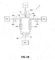
- FIGS. 1a and 1b represents a schematic of the system 2 of the present invention for delivering a base material to a packaging machine.
- the packaging machine is not shown in detail in the drawings and is not limited hereby, except that the packaging machine is suitable for packaging reactive components into a partitioned package.
- One non-limiting example of a packaging machine is the packaging machine shown and described in United States Patent No. 3,889,446 (Simmons et al. ), the contents of which are expressly incorporated herein by reference.
- a system 2 is provided to produce a resin cartridge containing up to three portions where each portion contains a resin and associated catalyst.
- the resin and catalyst components are initially kept separate from one another within the package by way of a barrier. Rupturing of the barrier causes the resin and catalyst to mix, effecting cure of the resulting mixture.
- the resin/catalyst mixture associated with at least one of the portions sets at a rate distinct or different from the setting rate of a resin/catalyst mixture associated with another portion of the resin cartridge. In this sense, the resin cartridge is considered a multi-speed resin cartridge.
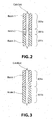
- FIG. 2 shows an example of a cartridge containing three portions (201a, 201b, 201c).
- the resin and catalyst components in each of portions 201a-c sets at a speed that is unique from the speed at which a mixture of the resin and catalyst components of another portion would set.
- the resin/catalyst combination in portion 201a set a first speed
- the resin/catalyst combination in portion 201b set at a second speed
- the resin/catalyst combination in portion 201c set at a third speed.
- FIG. 1 shows an example of a cartridge containing three portions (201a, 201b, 201c).
- the cartridge contains two portions (301a, 301b), each including a resin and associated catalyst that, when mixed, create a mixture that sets at a distinct rate from a corresponding mixture of the resin and catalyst in the other portion.
- portions 301a, 301b
- each including a resin and associated catalyst that, when mixed, create a mixture that sets at a distinct rate from a corresponding mixture of the resin and catalyst in the other portion.
- cartridges having more than three portions are also envisioned.
- a base material which may be, for example, a catalyst or resin
- Base material supply source 10 is intended to represent any element or combination of elements that can act to supply a base material, such as a catalyst or resin, to downstream portions of system 2.
- base material supply source 10 is a supply tank (not shown) containing large quantities of a base material that is continually refilled and replenished by a constant or repeated influx of base material.
- a series of valves, pumps, mixers and pipes could also be provided in an operational relationship with a supply tank to properly distribute the base material to the system 2.
- base material supply source 10 could be the output section of a system for producing a base material through mixing, reacting and/or combining various chemical compounds and other additives.
- base material supply source 10 could be the output section of a system for producing a base material through mixing, reacting and/or combining various chemical compounds and other additives.
- the details of preparing useful base materials such as catalysts and/or resins is beyond the scope of this application, but would be understood by those skilled in the art.
- the base material is a catalyst
- potential, non-limiting catalysts for use as the base catalyst include, but are not limited to, peroxide types such as benzoyl peroxide (BPO) with a water or oil base.
- BPO benzoyl peroxide
- Other such catalysts include cyclohexone peroxide, hydroxyl heptyl peroxide, 1-hydroxy cyclohexyl hydroperoxide-1, t-butyl hydroperoxide, 2, 4-dichlorobenzoyl peroxide and the like, methyl ethyl ketone peroxide as well as inorganic peroxides alone or mixed with organic peroxides, such as sodium percarbonate, calcium peroxide, or sodium peroxide.
- Potential catalysts are listed in United States Patent No. 3,324,663 (McLean ), the contents of which are expressly incorporated herein by reference. Such catalysts are commercially available from a variety of sources.
- the base material can also be a resin.
- resins for use as the base resin include, but are not limited to, polyester with a styrene monomer cross-linking agent as well as acrylates and acrylic resins and combinations thereof, unsaturated polyester resins dissolved in suitable ethylenically unsaturated monomer or mixture of monomers such as styrene, alpha methyl styrene, vinyl toluene, and methyl methacrylate.
- Potential resins are provided in United States Patent Nos. 3,731,791 (Fourcade et al. ) and 5,993,116 (Paxton et al. ), the contents of which are expressly incorporated herein by reference. Such resins are commercially available from a variety of sources.
- the base material provided by base material supply source 10 may also contain additives such as fillers or other particulate matter.
- additives such as fillers or other particulate matter.
- the relative amount of particulate matter that is added to, for instance, a catalyst or resin, as a filler material affects the cost and performance of the final resin cartridge.
- Potential fillers for use with the system include, but are not limited to, limestone, fly ash, sand, and talc, and limestone is particularly useful.
- Additional fillers may include calcite, granite, basalt, dolomite, andesite, feldspars, amphiboles, pyroxenes, olivine, iron oxides, gabbro, rhyolite, syenite, diorite, dolerite, peridotite, trachyte, obsidian, quartz, vitrified clay, slag, cinders, and glass cullet.
- the base materials described herein may include these filler materials or other additional materials, as would be appreciated by one skilled in the art.
- Mass meters can be employed to accurately control the amount of fillers added to a base material.
- filler may be added to the base material at base material supply source 10 or at a point upstream of base material supply source 10 such as in a mixing station. While the base material provided to system 2 from base material supply source 10 may already contain the appropriate levels of filler material, system 2 can additionally include subsystems (not shown) downstream of base material supply source 10 for adding filler materials at various points throughout system 2 prior to packaging machine PM-1.
- Base material is transferred from base material supply source 10 through base material supply line 12 to a downstream section of system 2. This transfer can be accomplished via a system of valves and pumps, and a metering pump 40a, such as a mass or volume meter, may be useful to measure and control the flow rate of base material from base material supply source 10.
- a metering pump 40a such as a mass or volume meter
- base material supply line 12 can "split" into multiple branch lines 14a, 14b. This split point is designated as point “A" in FIG. 1 . It is also contemplated that one or more branch lines 14a, 14b can extend directly from base material supply source 10, so long as fluid communication exists between base material supply source 10 and branch lines 14a, 14b. While only two branch lines are shown, it is anticipated that a system having additional branch lines, such as three, four, or five, could be used. The flow of base material continues downstream through the respective branch lines 14a, 14b as shown by the arrows in FIG. 1 , which designate the general direction of flow through the system.
- a branch line such as branch line 14a
- Altering material supply line 24a can extend between altering material supply source 20a and branch line 14a. Altering material can be transferred from altering material supply source 20a through altering material supply line 24a to branch line 14a via a system of valves and pumps, and a metering pump 40b, such as a mass or volume pump, may be useful to measure and control the flow rate of altering material from altering material supply source 20a to branch line 14a.
- another branch line such as branch line 14b
- another branch line can come into fluid communication with another altering material supply line 24b.
- Altering material supply line 24b can extend between altering material supply source 20b and branch line 14b. Altering material can be transferred from altering material supply source 20b through altering material supply line 24b to branch line 14b via a system of valves and pumps, and a metering pump 40c may be useful to measure and control the flow rate of altering material from altering material supply source 20b to branch line 14b.
- branch lines 14a, 14b is not particularly limited, and may be varied depending on, for example, the number of altering material supply lines in communication therewith. However, shorter branch lines 14a, 14b can be replaced more easily and in a cost effective manner in the event they become contaminated or stained by the passing base material if it is desired to use the system 2 with another base material.
- Branch lines 14a, 14b, as well as altering material supply lines 24a, 24b, product line 18 (each discussed below) and other material lines that may be utilized in the invention can be made of any suitable material, with metal or plastic cylindrical tubing or piping being preferred.
- the flow rate of altering material through altering material supply lines 24a, 24b and into branch lines 14a, 14b can be adjusted based on the total flow rate of the base material in branch lines 14a, 14b after addition of the altering material.
- the flow rate of altering material is no more than 5% (by volume) of the flow rate of the base material, such as 1% by volume or less.
- Altering material supply sources 20a, 20b can each provide a material that, when added to the base material, whether it be a catalyst, resin, or other material, can affect or alter the setting time of the resin/catalyst mixture in the resin cartridge containing the base material modified with the altering material.
- the amount of altering material added to the base material is determined primarily by the type of altering material, the effect the altering material has on the setting time, and the desired setting time of the final resin/catalyst mixture.
- the altering material can be selected to be a material that will either inhibit or promote the reaction (i.e., slow down or speed up the setting time) between the catalyst and the associated resin in a resin cartridge upon rupturing of a partition in the resin cartridge or otherwise allowing the catalyst and resin to mix.
- the altering material can be one which will either promote or inhibit the reaction between the resin and the associated catalyst in a resin cartridge.
- each of the altering material supply sources 20a, 20b provides a different altering material or a different concentration of the same altering material.
- useful altering materials include inhibitor and promoter compounds.
- useful inhibitors include, but are not limited to, naphthoquinone as well as hydropuinone, monoalkyl phenols, including monotertiary butyl phenol, monotertiary butyl hydroquinone, ortho-, meta- and para- cresol, higher alkyl phenols, polyhydricphenols, including catechol, resorcinol, and the partially alkylated polyhydric phenols, including eugenol, guaiacol, and mixtures of these, as listed in United States Patent No.
- Altering material supply sources 20a, 20b represent any element or combination of elements that can act to supply an altering material to altering material supply lines 24a, 24b.
- altering material supply sources 20a, 20b are supply tanks containing large quantities of the altering material that can continually be replenished. A series of valves, pumps, mixers and pipes can be provided in operational relationship with the tanks to distribute the altering material into altering material supply lines 24a, 24b.
- altering material supply sources 20a, 20b could be the output portion of a system for producing an altering material through mixing, reacting and/or combining various chemical compounds and other additives. The details of preparing useful altering materials is beyond the scope of this application, but would be understood by those skilled in the art.
- modifiers including modifiers that may or may not significantly affect the cure speed of a resin/catalyst mixture, such as stabilizers, gelling agents, thickeners, dyes and pigments
- additive of these modifiers can be done by incorporating them into the altering material(s) at, upstream, or downstream of the altering material supply sources 20a, 20b or by a separate process in which one or more modifier supply lines (not shown) are provided in fluid communication with branch lines 14a, 14b in a manner similar to that described above with respect to the interaction between altering material supply lines 24a, 24b and branch lines 14a, 14b.
- a dye material is mixed with the altering material either at the altering material supply source 20a, 20b or at another point along the altering material supply line 24a, 24b.
- the dye material, along with the altering material is then combined with the base material in branch lines 14a, 14b. Because the altering material can be selected to alter the setting speed of a resin/catalyst mixture from the setting speed of a resin/catalyst mixture that does not include the altering material, adding a dye material simultaneously with the altering material provides certain advantages.
- the dye for example, by combining the dye with the altering material (which is then added to the base material), one can visually determine where in the resin cartridge the base material supplemented with altering material is disposed based on the presence (or absence) of the dye material. In a resin cartridge, this is an easy and accurate way of determining the relative setting times of the various portions (201a-c, 301a-b) along the length of the cartridge.
- the color of the dyes selected are each unique from one another and also unique from the original color of the base material.
- branch line 14a, 14b could have no associated altering material supply line 24a, 24b to allow the base material to flow through any or all branch lines 14a, 14b of system 2 to packaging machine PM-1 without being modified by the altering material.
- a similar effect can be produced by simply stopping flow from one of the altering material supply lines 24a, 24b for an appropriate time period to allow the base material in the corresponding branch line 14a, 14b to flow through system 2 without having altering material added thereto.
- mixing devices 30a, 30b can be used to ensure a proper level of integration of the base material and the added materials, such as the altering materials, dyes, etc.
- mixing devices 30a, 30b are static mixers, for example mixers comprised of baffles incorporated within branch lines 14a, 14b.
- Mixing devices 30a, 30b can be incorporated along one section of branch lines 14a, 14b, along multiple sections, or along the entire length of branch lines 14a, 14b.
- mixing device 30a, 30b is disposed immediately after the point where the altering material is added to branch lines 14a, 14b to ensure that the altering material and/or dye material adequately mixes with the base material.
- the mixing apparatus can ensure that the base material and added materials is at least 50% mixed, such as uniformly mixed.
- mixing by mixing devices 30a, 30b may be less than 1%, so that mixing occurs during use of resin cartridge in a bore hole.
- valve arrangement 50 can include a single 3-way valve configured to independently select base material flow from one of the branch lines 14a, 14b as an input to the valve and allowing the base material contained in the selected valve input source to pass through valve arrangement, 50 as a valve arrangement output composition and into product line 18. All flow from the unselected branch lines 14a, 14b can be stopped at the inlet to valve arrangement 50. If there are, for example, three branch lines, valve arrangement 50 can include a 4-way valve configured to independently select base material flow from one or more of the branch lines. Valves that can accept multiple input streams and select among the multiple input streams to provide a single output stream are considered "multi-input" valves for purposes of this application.
- a valve arrangement 50 comprised of a single 3-way valve is shown in FIG. 1a .
- the valve arrangement 50 can include a separate, single input/single output valve associated with each of the branch lines 14a, 14b.
- a separate, single input/single output valve associated with each of the branch lines 14a, 14b.
- the separate valves can operate in conjunction with one another to provide base material flow from a particular branch line 14a, 14b to product line 18 at a given time.
- Valves of valve arrangement 50 can be any type of available valve. Non-limiting examples of types of valves that can be used include ball valves and rotor valves. Valves of valve arrangement 50 should be able to quickly switch between the various input ports or between an open and closed position. In a preferred embodiment, the switch time between a first and second input port, or between an open and closed position if the valve has a single input, is 16 milliseconds or less, such as 0.8 milliseconds or less.
- the switching time of valve can also be tied to the volume of base material to be provided to the resin cartridge.
- the switching time of such a valve is sufficiently quick that the volume of base material provided by valve during the switching operation fills 2.0 inch or less, such as 0.2 inch or less, of the associated compartment of the resin cartridge.
- the valve(s) of valve arrangement 50 are sized so that the volume of base material contained within a valve at a given time is 2.0% or less, such as 0.2% or less, of the volume of the resin cartridge. By limiting the amount of material that passes through valve while transitioning between inputs, the transition length in the cartridge is also limited.
- Valve(s) of valve arrangement 50 should also be able to handle thick materials flowing in a laminar or near laminar fashion into the input ports. Valves should be made of a resilient material that can withstand prolonged exposure to corrosive materials. Valves should also be capable of being automated when connected to an appropriate computer network.
- a product line 18 can extend from valve arrangement 50 and into packaging machine PM-1 in order to transfer the valve arrangement output composition to packaging machine PM-1 where the composition is then injected into the appropriate compartment of the resin cartridge.
- the distance from valve arrangement 50 to packaging machine PM-1 is preferably short, such as between one and three feet, to allow the base material flowing into packaging machine PM-1 to quickly correspond to the base material from the selected valve input source without an undue delay period in which the previously selected valve input source continues to flow into packaging machine PM-1. In other words, a short product line 18 is preferred.
- Packaging machine PM-1 receives a base material, in the form of valve arrangement output composition, from product line 18 for injection into one compartment of a resin cartridge and another material from a separate supply pipe (not shown) for injection into a separate compartment.
- a base material in the form of valve arrangement output composition
- the system 2 can be used in conjunction with a system for providing resin to the packaging machine PM-1.
- the resin system could provide resin to packaging machine PM-1 for injection into one compartment of the resin cartridge while the system 2 could provide catalyst to packaging machine PM-1 for injection into a separate compartment of the resin cartridge.
- the system 2 described above is used with a resin as a base material
- the system 2 can be used in conjunction with a system for providing catalyst to the packaging machine PM-1 to create a resin cartridge.
- a suitable packaging machine PM-1 is described in United States Patent No. 3,889,446 (Simmons et al. ). Generally, such packaging machines produce resin cartridges by forming a web of pliable film into an advancing first tube with the edges of the tube overlapping each other. A second tube is formed therein by advancing another film into the first tube, thereby creating a second tube within the first tube, i.e., one compartment within another compartment. Alternatively, an edge of the first tube may span the diameter of the tube to create side-by-side compartments. These are only examples of packaging techniques and are not meant to be limiting. Packaging machine PM-1 further may include one or more packaging pumps for delivering materials into the two compartments of the packaging.
- Packaging machine PM-1 seals the compartments together and cuts the length of filled packaging at the seal, yielding a cartridge with one compartment containing a base material provided from system 2, optionally having along its length amounts of base material of different setting speeds, and another compartment containing another material that can react with the base material. It is also envisioned that packaging machine PM-1 can create a compartment that is partitioned along its length to separate, for instance, one section of base material having a first amount or type of altering material from a second section of base material having a second amount or type of altering material.
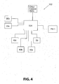
- the system of the present invention can include a computer network 102 for controlling system 2 via a remote station.
- Network 102 includes numerous components in mutual communication via a central processor 104.
- Central processor 104 can be programmed for controlling and coordinating the delivery rates of base material and altering materials by, for example, controlling the flow rates through metering pumps 40a-c.
- Central processor 104 can also be programmed to control and coordinate delivery of filler, additives, dyes and modifiers.
- central processor 104 can be programmed to activate the operation of valve arrangement 50 in order to transition the source of the valve arrangement output composition provided to product line 18 from a first branch line 14a to a second or subsequent branch line 14b.
- Central processor 104 also coordinates with packaging machine PM-1 to ensure the resin cartridges are produced with the appropriate amount of base material and other materials that may be supplied by a separate pipe.
- the flow rate of altering material may be synchronized with packaging machine PM-1 and valve arrangement 50 to provide the desired setting time and indexing to the cartridge clips or ends of the cartridge in order to allow the packaging film to be marked to show the different portions.
- Branch lines 14a-n could all originate from a common split point A in supply line 12 or system 2 could contain multiple split points where a first branch line 14a subsequently splits into two or more branch lines at a point downstream from the original split point A. As mentioned above, one or more of branch lines 14a-n could also originate at the base material supply source 10. Increasing the number of branch lines increases the number of different (modified) base materials that can be provided to packaging machine PM-1.
- Each branch line 14a-n could be provided in fluid communication with corresponding altering material supply lines 24a-n and/or modifier lines to provide inhibitors, promoters, dyes, modifiers, etc., to the base material in branch lines 14a-n.
- valve arrangement 50 could include a 4-way valve, including inlets for all three branch lines 14a-c as well as a single outlet for product line 18.
- valve arrangement, 50 could include a 6-way valve, including inlets for all five branch lines 14a-e as well as a single outlet for product line 18.
- the systems 2, 102, 104 described herein may be used in conjunction with or as a subset of the systems described in United States Patent Application Publication No. 2008/0120947 (Oldsen et al. ), issued as United States Patent No. 7,637,086 .
- the method includes a step of providing a base material, such as from a base material supply source.
- the base material can be, for example, a resin or a catalyst.
- the method further includes a step of feeding the base material into a plurality of branch lines. This can be accomplished such as described above, where the base material supply line 10 "splits," such as at split point "A,” into two or more branch lines 14a, 14b.
- the method further includes a step of adding at least one altering material to the base material flowing through at least one of the branch lines 14a, 14b.
- the altering material can be provided from an altering material supply source 20a, 20b through an altering material supply line 24a, 24b in fluid communication with a corresponding branch line 14a, 14b.
- the altering material can be, for example, a promoter or an inhibitor.
- the method can further include a step of adding a dye to the base material.
- the dye can be added in various ways. For instance, the dye can be added to the altering material or the dye can be added directly to the base material at a point along one of the branch lines 14a, 14b.
- the method also includes a step of feeding each of the branch lines 14a, 14b into a valve arrangement 50.
- the valve arrangement 50 can select from between the various branch lines 14a, 14b and provide an output composition, which corresponds to the base material in the selected branch line, as an output of the valve assembly 50. This output is then transferred to a packaging machine PM-1 where it is injected into a resin cartridge.
- the present system and method allows for the production of resin cartridges in a more efficient and effective manner than with prior art systems and methods.
- a single stream of base material can be provided to the system at a substantially constant mass flow rate.
- Splitting the input base material into a plurality of branch lines, adding the altering materials, dyes and other modifiers to the base material in the individual branch lines, and then selecting from among the various branch lines as the input to the packaging machine using a quick-changing valve assembly allows for the base material to maintain a more steady flow through the system. This greatly reduces the momentum changes that are necessary when stopping and starting the flow of the base material as well as the starting and stopping of the pump providing the base material from the base material supply source.
- valves in the valve arrangement that can quickly toggle between the selected input (for a multi-input valve) or between open and closed (for a single input/output valve) create clean cutoffs in the type of base material provided to the packaging machine, resulting in sharper transitions between the different portions or sections of the resin cartridge.
Landscapes
- Engineering & Computer Science (AREA)
- Mining & Mineral Resources (AREA)
- Geochemistry & Mineralogy (AREA)
- Structural Engineering (AREA)
- Life Sciences & Earth Sciences (AREA)
- General Life Sciences & Earth Sciences (AREA)
- Mechanical Engineering (AREA)
- Geology (AREA)
- Processing And Handling Of Plastics And Other Materials For Molding In General (AREA)
- Casting Or Compression Moulding Of Plastics Or The Like (AREA)
- Package Specialized In Special Use (AREA)
- Adhesives Or Adhesive Processes (AREA)
- Heating, Cooling, Or Curing Plastics Or The Like In General (AREA)
Priority Applications (1)
| Application Number | Priority Date | Filing Date | Title |
|---|---|---|---|
| PL10829148T PL2496481T3 (pl) | 2009-11-05 | 2010-11-05 | Układ produkcji wkładów z żywicą o wielu prędkościach [utwardzania] |
Applications Claiming Priority (2)
| Application Number | Priority Date | Filing Date | Title |
|---|---|---|---|
| US25829609P | 2009-11-05 | 2009-11-05 | |
| PCT/US2010/055614 WO2011057068A1 (en) | 2009-11-05 | 2010-11-05 | Multi-speed resin cartridge production system |
Publications (3)
| Publication Number | Publication Date |
|---|---|
| EP2496481A1 EP2496481A1 (en) | 2012-09-12 |
| EP2496481A4 EP2496481A4 (en) | 2013-11-13 |
| EP2496481B1 true EP2496481B1 (en) | 2015-03-04 |
Family
ID=43924106
Family Applications (1)
| Application Number | Title | Priority Date | Filing Date |
|---|---|---|---|
| EP20100829148 Active EP2496481B1 (en) | 2009-11-05 | 2010-11-05 | Multi-speed resin cartridge production system |
Country Status (12)
| Country | Link |
|---|---|
| US (1) | US8567437B2 (pl) |
| EP (1) | EP2496481B1 (pl) |
| CN (1) | CN102666287A (pl) |
| AU (1) | AU2010315091C1 (pl) |
| BR (1) | BR112012010557A2 (pl) |
| CA (1) | CA2779690A1 (pl) |
| CO (1) | CO6551682A2 (pl) |
| ES (1) | ES2537161T3 (pl) |
| MX (1) | MX2012005285A (pl) |
| PL (1) | PL2496481T3 (pl) |
| WO (1) | WO2011057068A1 (pl) |
| ZA (1) | ZA201203190B (pl) |
Families Citing this family (5)
| Publication number | Priority date | Publication date | Assignee | Title |
|---|---|---|---|---|
| US9120614B2 (en) * | 2010-10-13 | 2015-09-01 | Dsi Underground Systems, Inc. | Method for preserving the firmness and internal pressure of a resin cartridge and improving the shelf-life of a resin cartridge |
| US10060393B2 (en) * | 2013-02-11 | 2018-08-28 | Ford Global Technologies, Llc | Purge valve and fuel vapor management system |
| CN104481857A (zh) * | 2014-12-05 | 2015-04-01 | 苏州慧捷自动化科技有限公司 | 一种压缩机在线长时间跑合系统 |
| AU2016201180B2 (en) * | 2016-02-25 | 2022-01-06 | Metrik Properties Pty Ltd | An injection system, method of manufacturing and dual conduit delivery tube for reducing resin intermixing during the manufacture of dual set time resin capsules |
| EP4045281A1 (de) * | 2019-10-15 | 2022-08-24 | Reifenhäuser GmbH & Co. KG Maschinenfabrik | Schmelzeleiter für ein extrusionswerkzeug einer extrusionsanlage, extrusionswerkzeug, extrusionsanlage und verfahren zum betreiben einer solchen extrusionsanlage |
Family Cites Families (20)
| Publication number | Priority date | Publication date | Assignee | Title |
|---|---|---|---|---|
| US3324663A (en) * | 1963-10-21 | 1967-06-13 | American Cyanamid Co | Rock bolting |
| GB1127914A (en) * | 1965-10-05 | 1968-09-18 | Exchem Holdings | Bolt head for use with resinous securing compositions |
| US3474898A (en) * | 1967-05-15 | 1969-10-28 | American Cyanamid Co | Package of reactable components |
| US3996722A (en) * | 1972-06-19 | 1976-12-14 | Frederick William Bernhardt | Method of making a cartridge |
| US3861522A (en) * | 1972-08-16 | 1975-01-21 | Du Pont | Compartmented package having variable-volume compartments |
| US3889446A (en) * | 1974-06-18 | 1975-06-17 | Du Pont | Process for forming partitioned film packages and apparatus for use therein |
| US4346546A (en) * | 1978-10-16 | 1982-08-31 | Sidney Tasker | Automatic flexible container fabricating machine |
| US4257438A (en) * | 1978-11-16 | 1981-03-24 | Miller Donald V | Bulk catalyst proportioner |
| US4239105A (en) * | 1979-08-02 | 1980-12-16 | General Electric Company | Resin capsule for mining roof bolting systems |
| US4280943A (en) * | 1979-11-08 | 1981-07-28 | E. I. Du Pont De Nemours & Co. | Organic grouting composition for anchoring a bolt in a hole |
| FR2483512A1 (fr) * | 1980-05-30 | 1981-12-04 | Explosifs Prod Chim | Procede de scellement de tiges ou boulons d'ancrage pour galeries de mines, cartouches inorganiques correspondantes, et procedes de preparation |
| US4497403A (en) * | 1983-06-24 | 1985-02-05 | Celtite, Inc. | Cartridge containing multiple areas of a multi-component mix and method of making the same |
| JPS60161724A (ja) * | 1984-02-01 | 1985-08-23 | Toshiba Corp | 混合制御装置 |
| US5205322A (en) * | 1992-06-17 | 1993-04-27 | Puritan-Bennett Corporation | Method and apparatus for flow control for sensor calibration |
| US5965635A (en) * | 1995-06-07 | 1999-10-12 | Illinois Tool Works Inc. | Alkylacrylate ester composition for anchoring materials in or to concrete or masonry |
| JP3333121B2 (ja) * | 1996-12-25 | 2002-10-07 | 東京エレクトロン株式会社 | 塗布装置 |
| US5993116A (en) * | 1997-06-30 | 1999-11-30 | Sandvik Rock Tools, Inc. | Filler-containing rock bolt anchoring system and method of preparation thereof |
| ZA200605213B (en) * | 2005-06-24 | 2007-09-26 | J Lok Co | Device for forming partitioned film packages |
| US7637086B2 (en) * | 2006-11-29 | 2009-12-29 | J-Lok Co. | System and method for producing resin cartridges |
| US7775745B2 (en) * | 2009-01-20 | 2010-08-17 | J-Lok Co. | Anchoring systems and methods of use thereof |
-
2010
- 2010-11-05 PL PL10829148T patent/PL2496481T3/pl unknown
- 2010-11-05 CN CN2010800579940A patent/CN102666287A/zh active Pending
- 2010-11-05 US US12/940,342 patent/US8567437B2/en active Active
- 2010-11-05 MX MX2012005285A patent/MX2012005285A/es active IP Right Grant
- 2010-11-05 ES ES10829148.5T patent/ES2537161T3/es active Active
- 2010-11-05 EP EP20100829148 patent/EP2496481B1/en active Active
- 2010-11-05 AU AU2010315091A patent/AU2010315091C1/en active Active
- 2010-11-05 CA CA 2779690 patent/CA2779690A1/en not_active Abandoned
- 2010-11-05 BR BR112012010557A patent/BR112012010557A2/pt not_active IP Right Cessation
- 2010-11-05 WO PCT/US2010/055614 patent/WO2011057068A1/en not_active Ceased
-
2012
- 2012-05-03 ZA ZA2012/03190A patent/ZA201203190B/en unknown
- 2012-05-16 CO CO12081053A patent/CO6551682A2/es not_active Application Discontinuation
Also Published As
| Publication number | Publication date |
|---|---|
| WO2011057068A1 (en) | 2011-05-12 |
| PL2496481T3 (pl) | 2015-10-30 |
| CN102666287A (zh) | 2012-09-12 |
| CO6551682A2 (es) | 2012-10-31 |
| CA2779690A1 (en) | 2011-05-12 |
| BR112012010557A2 (pt) | 2019-09-24 |
| EP2496481A4 (en) | 2013-11-13 |
| AU2010315091C1 (en) | 2016-01-28 |
| US8567437B2 (en) | 2013-10-29 |
| AU2010315091A1 (en) | 2012-05-31 |
| EP2496481A1 (en) | 2012-09-12 |
| ZA201203190B (en) | 2013-01-30 |
| AU2010315091B2 (en) | 2015-09-17 |
| ES2537161T3 (es) | 2015-06-03 |
| MX2012005285A (es) | 2012-08-03 |
| US20110100470A1 (en) | 2011-05-05 |
Similar Documents
| Publication | Publication Date | Title |
|---|---|---|
| EP2496481B1 (en) | Multi-speed resin cartridge production system | |
| Pojman | Frontal polymerization | |
| CN105637180B (zh) | 自钻式锚杆组件和安装方法 | |
| AU2010206829B2 (en) | Anchoring systems and methods of use thereof | |
| RU2480329C2 (ru) | Применение устройства, обеспечивающего создание нити из пастообразного материала | |
| US8539992B2 (en) | Apparatus and method for anchor bolt grouting | |
| CN109642462A (zh) | 可泵送树脂系统 | |
| NO311540B1 (no) | Fremgangsmåte og anordning for lagring og blanding av materialer i et borehull | |
| US9738405B2 (en) | Resin cartridge production system | |
| KR100952646B1 (ko) | 중합체 변형 석고막 및 그 용도 | |
| US3861155A (en) | Pumpable rockbolt method | |
| JP2002097446A (ja) | 粘性があるアミン硬化性の化学的固着用接着剤 | |
| AU2021258480B2 (en) | Apparatus for resin injection, mining machine and method | |
| JP2009019332A (ja) | 多点地盤同時注入による地盤強化方法 | |
| US3930639A (en) | Pumpable rockbolt method | |
| CN120882950A (zh) | 用于给送散装树脂的布置、采矿机器及方法 | |
| CN118008417A (zh) | 钻孔围岩修复与锚固增强的锚杆自动化安装方法 | |
| Steinberg et al. | Pumpable rockbolt method |
Legal Events
| Date | Code | Title | Description |
|---|---|---|---|
| PUAI | Public reference made under article 153(3) epc to a published international application that has entered the european phase |
Free format text: ORIGINAL CODE: 0009012 |
|
| 17P | Request for examination filed |
Effective date: 20120514 |
|
| AK | Designated contracting states |
Kind code of ref document: A1 Designated state(s): AL AT BE BG CH CY CZ DE DK EE ES FI FR GB GR HR HU IE IS IT LI LT LU LV MC MK MT NL NO PL PT RO RS SE SI SK SM TR |
|
| AX | Request for extension of the european patent |
Extension state: BA ME |
|
| REG | Reference to a national code |
Ref country code: DE Ref legal event code: R079 Ref document number: 602010022935 Country of ref document: DE Free format text: PREVIOUS MAIN CLASS: B65B0035540000 Ipc: B65B0029100000 |
|
| A4 | Supplementary search report drawn up and despatched |
Effective date: 20131015 |
|
| RIC1 | Information provided on ipc code assigned before grant |
Ipc: B65B 29/10 20060101AFI20131009BHEP |
|
| GRAP | Despatch of communication of intention to grant a patent |
Free format text: ORIGINAL CODE: EPIDOSNIGR1 |
|
| INTG | Intention to grant announced |
Effective date: 20140919 |
|
| GRAS | Grant fee paid |
Free format text: ORIGINAL CODE: EPIDOSNIGR3 |
|
| GRAA | (expected) grant |
Free format text: ORIGINAL CODE: 0009210 |
|
| AK | Designated contracting states |
Kind code of ref document: B1 Designated state(s): AL AT BE BG CH CY CZ DE DK EE ES FI FR GB GR HR HU IE IS IT LI LT LU LV MC MK MT NL NO PL PT RO RS SE SI SK SM TR |
|
| AX | Request for extension of the european patent |
Extension state: BA ME |
|
| REG | Reference to a national code |
Ref country code: GB Ref legal event code: FG4D |
|
| REG | Reference to a national code |
Ref country code: CH Ref legal event code: EP |
|
| REG | Reference to a national code |
Ref country code: IE Ref legal event code: FG4D |
|
| REG | Reference to a national code |
Ref country code: AT Ref legal event code: REF Ref document number: 713620 Country of ref document: AT Kind code of ref document: T Effective date: 20150415 |
|
| REG | Reference to a national code |
Ref country code: DE Ref legal event code: R096 Ref document number: 602010022935 Country of ref document: DE Effective date: 20150416 |
|
| REG | Reference to a national code |
Ref country code: ES Ref legal event code: FG2A Ref document number: 2537161 Country of ref document: ES Kind code of ref document: T3 Effective date: 20150603 |
|
| REG | Reference to a national code |
Ref country code: SE Ref legal event code: TRGR |
|
| REG | Reference to a national code |
Ref country code: EE Ref legal event code: FG4A Ref document number: E010586 Country of ref document: EE Effective date: 20150602 Ref country code: NL Ref legal event code: VDEP Effective date: 20150304 |
|
| REG | Reference to a national code |
Ref country code: NO Ref legal event code: T2 Effective date: 20150304 |
|
| PG25 | Lapsed in a contracting state [announced via postgrant information from national office to epo] |
Ref country code: HR Free format text: LAPSE BECAUSE OF FAILURE TO SUBMIT A TRANSLATION OF THE DESCRIPTION OR TO PAY THE FEE WITHIN THE PRESCRIBED TIME-LIMIT Effective date: 20150304 Ref country code: FI Free format text: LAPSE BECAUSE OF FAILURE TO SUBMIT A TRANSLATION OF THE DESCRIPTION OR TO PAY THE FEE WITHIN THE PRESCRIBED TIME-LIMIT Effective date: 20150304 Ref country code: LT Free format text: LAPSE BECAUSE OF FAILURE TO SUBMIT A TRANSLATION OF THE DESCRIPTION OR TO PAY THE FEE WITHIN THE PRESCRIBED TIME-LIMIT Effective date: 20150304 |
|
| REG | Reference to a national code |
Ref country code: LT Ref legal event code: MG4D |
|
| PG25 | Lapsed in a contracting state [announced via postgrant information from national office to epo] |
Ref country code: RS Free format text: LAPSE BECAUSE OF FAILURE TO SUBMIT A TRANSLATION OF THE DESCRIPTION OR TO PAY THE FEE WITHIN THE PRESCRIBED TIME-LIMIT Effective date: 20150304 Ref country code: LV Free format text: LAPSE BECAUSE OF FAILURE TO SUBMIT A TRANSLATION OF THE DESCRIPTION OR TO PAY THE FEE WITHIN THE PRESCRIBED TIME-LIMIT Effective date: 20150304 Ref country code: GR Free format text: LAPSE BECAUSE OF FAILURE TO SUBMIT A TRANSLATION OF THE DESCRIPTION OR TO PAY THE FEE WITHIN THE PRESCRIBED TIME-LIMIT Effective date: 20150605 |
|
| REG | Reference to a national code |
Ref country code: SK Ref legal event code: T3 Ref document number: E 18759 Country of ref document: SK |
|
| PG25 | Lapsed in a contracting state [announced via postgrant information from national office to epo] |
Ref country code: NL Free format text: LAPSE BECAUSE OF FAILURE TO SUBMIT A TRANSLATION OF THE DESCRIPTION OR TO PAY THE FEE WITHIN THE PRESCRIBED TIME-LIMIT Effective date: 20150304 |
|
| PG25 | Lapsed in a contracting state [announced via postgrant information from national office to epo] |
Ref country code: RO Free format text: LAPSE BECAUSE OF FAILURE TO SUBMIT A TRANSLATION OF THE DESCRIPTION OR TO PAY THE FEE WITHIN THE PRESCRIBED TIME-LIMIT Effective date: 20150304 Ref country code: PT Free format text: LAPSE BECAUSE OF FAILURE TO SUBMIT A TRANSLATION OF THE DESCRIPTION OR TO PAY THE FEE WITHIN THE PRESCRIBED TIME-LIMIT Effective date: 20150706 |
|
| REG | Reference to a national code |
Ref country code: PL Ref legal event code: T3 |
|
| PG25 | Lapsed in a contracting state [announced via postgrant information from national office to epo] |
Ref country code: IS Free format text: LAPSE BECAUSE OF FAILURE TO SUBMIT A TRANSLATION OF THE DESCRIPTION OR TO PAY THE FEE WITHIN THE PRESCRIBED TIME-LIMIT Effective date: 20150704 |
|
| REG | Reference to a national code |
Ref country code: DE Ref legal event code: R097 Ref document number: 602010022935 Country of ref document: DE |
|
| PG25 | Lapsed in a contracting state [announced via postgrant information from national office to epo] |
Ref country code: IT Free format text: LAPSE BECAUSE OF FAILURE TO SUBMIT A TRANSLATION OF THE DESCRIPTION OR TO PAY THE FEE WITHIN THE PRESCRIBED TIME-LIMIT Effective date: 20150304 |
|
| PLBE | No opposition filed within time limit |
Free format text: ORIGINAL CODE: 0009261 |
|
| STAA | Information on the status of an ep patent application or granted ep patent |
Free format text: STATUS: NO OPPOSITION FILED WITHIN TIME LIMIT |
|
| PG25 | Lapsed in a contracting state [announced via postgrant information from national office to epo] |
Ref country code: DK Free format text: LAPSE BECAUSE OF FAILURE TO SUBMIT A TRANSLATION OF THE DESCRIPTION OR TO PAY THE FEE WITHIN THE PRESCRIBED TIME-LIMIT Effective date: 20150304 |
|
| PGFP | Annual fee paid to national office [announced via postgrant information from national office to epo] |
Ref country code: NO Payment date: 20151111 Year of fee payment: 6 Ref country code: GB Payment date: 20151104 Year of fee payment: 6 Ref country code: TR Payment date: 20151030 Year of fee payment: 6 Ref country code: EE Payment date: 20151127 Year of fee payment: 6 |
|
| 26N | No opposition filed |
Effective date: 20151207 |
|
| PG25 | Lapsed in a contracting state [announced via postgrant information from national office to epo] |
Ref country code: SI Free format text: LAPSE BECAUSE OF FAILURE TO SUBMIT A TRANSLATION OF THE DESCRIPTION OR TO PAY THE FEE WITHIN THE PRESCRIBED TIME-LIMIT Effective date: 20150304 |
|
| PGFP | Annual fee paid to national office [announced via postgrant information from national office to epo] |
Ref country code: SK Payment date: 20151030 Year of fee payment: 6 |
|
| PG25 | Lapsed in a contracting state [announced via postgrant information from national office to epo] |
Ref country code: LU Free format text: LAPSE BECAUSE OF FAILURE TO SUBMIT A TRANSLATION OF THE DESCRIPTION OR TO PAY THE FEE WITHIN THE PRESCRIBED TIME-LIMIT Effective date: 20151105 Ref country code: MC Free format text: LAPSE BECAUSE OF FAILURE TO SUBMIT A TRANSLATION OF THE DESCRIPTION OR TO PAY THE FEE WITHIN THE PRESCRIBED TIME-LIMIT Effective date: 20150304 |
|
| REG | Reference to a national code |
Ref country code: CH Ref legal event code: PL |
|
| PG25 | Lapsed in a contracting state [announced via postgrant information from national office to epo] |
Ref country code: LI Free format text: LAPSE BECAUSE OF NON-PAYMENT OF DUE FEES Effective date: 20151130 Ref country code: CH Free format text: LAPSE BECAUSE OF NON-PAYMENT OF DUE FEES Effective date: 20151130 |
|
| REG | Reference to a national code |
Ref country code: IE Ref legal event code: MM4A |
|
| REG | Reference to a national code |
Ref country code: FR Ref legal event code: ST Effective date: 20160729 |
|
| PG25 | Lapsed in a contracting state [announced via postgrant information from national office to epo] |
Ref country code: BE Free format text: LAPSE BECAUSE OF FAILURE TO SUBMIT A TRANSLATION OF THE DESCRIPTION OR TO PAY THE FEE WITHIN THE PRESCRIBED TIME-LIMIT Effective date: 20150304 |
|
| REG | Reference to a national code |
Ref country code: AT Ref legal event code: UEP Ref document number: 713620 Country of ref document: AT Kind code of ref document: T Effective date: 20150304 |
|
| PG25 | Lapsed in a contracting state [announced via postgrant information from national office to epo] |
Ref country code: IE Free format text: LAPSE BECAUSE OF NON-PAYMENT OF DUE FEES Effective date: 20151105 |
|
| PG25 | Lapsed in a contracting state [announced via postgrant information from national office to epo] |
Ref country code: FR Free format text: LAPSE BECAUSE OF NON-PAYMENT OF DUE FEES Effective date: 20151130 |
|
| PGFP | Annual fee paid to national office [announced via postgrant information from national office to epo] |
Ref country code: SE Payment date: 20161111 Year of fee payment: 7 Ref country code: AT Payment date: 20161109 Year of fee payment: 7 Ref country code: ES Payment date: 20161111 Year of fee payment: 7 |
|
| PG25 | Lapsed in a contracting state [announced via postgrant information from national office to epo] |
Ref country code: BG Free format text: LAPSE BECAUSE OF FAILURE TO SUBMIT A TRANSLATION OF THE DESCRIPTION OR TO PAY THE FEE WITHIN THE PRESCRIBED TIME-LIMIT Effective date: 20150304 Ref country code: HU Free format text: LAPSE BECAUSE OF FAILURE TO SUBMIT A TRANSLATION OF THE DESCRIPTION OR TO PAY THE FEE WITHIN THE PRESCRIBED TIME-LIMIT; INVALID AB INITIO Effective date: 20101105 Ref country code: SM Free format text: LAPSE BECAUSE OF FAILURE TO SUBMIT A TRANSLATION OF THE DESCRIPTION OR TO PAY THE FEE WITHIN THE PRESCRIBED TIME-LIMIT Effective date: 20150304 |
|
| REG | Reference to a national code |
Ref country code: DE Ref legal event code: R119 Ref document number: 602010022935 Country of ref document: DE |
|
| REG | Reference to a national code |
Ref country code: EE Ref legal event code: MM4A Ref document number: E010586 Country of ref document: EE Effective date: 20161130 |
|
| REG | Reference to a national code |
Ref country code: NO Ref legal event code: MMEP |
|
| PG25 | Lapsed in a contracting state [announced via postgrant information from national office to epo] |
Ref country code: CY Free format text: LAPSE BECAUSE OF FAILURE TO SUBMIT A TRANSLATION OF THE DESCRIPTION OR TO PAY THE FEE WITHIN THE PRESCRIBED TIME-LIMIT Effective date: 20150304 |
|
| GBPC | Gb: european patent ceased through non-payment of renewal fee |
Effective date: 20161105 |
|
| PG25 | Lapsed in a contracting state [announced via postgrant information from national office to epo] |
Ref country code: EE Free format text: LAPSE BECAUSE OF NON-PAYMENT OF DUE FEES Effective date: 20161130 Ref country code: NO Free format text: LAPSE BECAUSE OF NON-PAYMENT OF DUE FEES Effective date: 20161130 Ref country code: SK Free format text: LAPSE BECAUSE OF NON-PAYMENT OF DUE FEES Effective date: 20161105 |
|
| REG | Reference to a national code |
Ref country code: SK Ref legal event code: MM4A Ref document number: E 18759 Country of ref document: SK Effective date: 20161105 |
|
| PG25 | Lapsed in a contracting state [announced via postgrant information from national office to epo] |
Ref country code: MT Free format text: LAPSE BECAUSE OF FAILURE TO SUBMIT A TRANSLATION OF THE DESCRIPTION OR TO PAY THE FEE WITHIN THE PRESCRIBED TIME-LIMIT Effective date: 20150304 |
|
| PG25 | Lapsed in a contracting state [announced via postgrant information from national office to epo] |
Ref country code: GB Free format text: LAPSE BECAUSE OF NON-PAYMENT OF DUE FEES Effective date: 20161105 Ref country code: DE Free format text: LAPSE BECAUSE OF NON-PAYMENT OF DUE FEES Effective date: 20170601 |
|
| PG25 | Lapsed in a contracting state [announced via postgrant information from national office to epo] |
Ref country code: MK Free format text: LAPSE BECAUSE OF FAILURE TO SUBMIT A TRANSLATION OF THE DESCRIPTION OR TO PAY THE FEE WITHIN THE PRESCRIBED TIME-LIMIT Effective date: 20150304 |
|
| REG | Reference to a national code |
Ref country code: SE Ref legal event code: EUG |
|
| REG | Reference to a national code |
Ref country code: AT Ref legal event code: MM01 Ref document number: 713620 Country of ref document: AT Kind code of ref document: T Effective date: 20171105 |
|
| PG25 | Lapsed in a contracting state [announced via postgrant information from national office to epo] |
Ref country code: AT Free format text: LAPSE BECAUSE OF NON-PAYMENT OF DUE FEES Effective date: 20171105 Ref country code: SE Free format text: LAPSE BECAUSE OF NON-PAYMENT OF DUE FEES Effective date: 20171106 |
|
| PG25 | Lapsed in a contracting state [announced via postgrant information from national office to epo] |
Ref country code: AL Free format text: LAPSE BECAUSE OF FAILURE TO SUBMIT A TRANSLATION OF THE DESCRIPTION OR TO PAY THE FEE WITHIN THE PRESCRIBED TIME-LIMIT Effective date: 20150304 |
|
| REG | Reference to a national code |
Ref country code: ES Ref legal event code: FD2A Effective date: 20181221 |
|
| PGFP | Annual fee paid to national office [announced via postgrant information from national office to epo] |
Ref country code: DE Payment date: 20181220 Year of fee payment: 9 |
|
| PG25 | Lapsed in a contracting state [announced via postgrant information from national office to epo] |
Ref country code: ES Free format text: LAPSE BECAUSE OF NON-PAYMENT OF DUE FEES Effective date: 20171106 |
|
| PG25 | Lapsed in a contracting state [announced via postgrant information from national office to epo] |
Ref country code: CZ Free format text: LAPSE BECAUSE OF NON-PAYMENT OF DUE FEES Effective date: 20191105 |
|
| PG25 | Lapsed in a contracting state [announced via postgrant information from national office to epo] |
Ref country code: TR Free format text: LAPSE BECAUSE OF NON-PAYMENT OF DUE FEES Effective date: 20161105 |
|
| P01 | Opt-out of the competence of the unified patent court (upc) registered |
Effective date: 20230514 |
|
| PGFP | Annual fee paid to national office [announced via postgrant information from national office to epo] |
Ref country code: PL Payment date: 20251024 Year of fee payment: 16 |