EP2495984A1 - Vorrichtung und verfahren zur anzeige stereoskopischer bilder - Google Patents
Vorrichtung und verfahren zur anzeige stereoskopischer bilder Download PDFInfo
- Publication number
- EP2495984A1 EP2495984A1 EP10855122A EP10855122A EP2495984A1 EP 2495984 A1 EP2495984 A1 EP 2495984A1 EP 10855122 A EP10855122 A EP 10855122A EP 10855122 A EP10855122 A EP 10855122A EP 2495984 A1 EP2495984 A1 EP 2495984A1
- Authority
- EP
- European Patent Office
- Prior art keywords
- weight
- image
- person
- display
- stereoscopic
- Prior art date
- Legal status (The legal status is an assumption and is not a legal conclusion. Google has not performed a legal analysis and makes no representation as to the accuracy of the status listed.)
- Withdrawn
Links
- 238000000034 method Methods 0.000 title claims description 4
- 238000010586 diagram Methods 0.000 description 14
- 230000003287 optical effect Effects 0.000 description 7
- 230000001276 controlling effect Effects 0.000 description 4
- 239000000203 mixture Substances 0.000 description 3
- 230000002596 correlated effect Effects 0.000 description 1
- 230000007423 decrease Effects 0.000 description 1
- 210000003128 head Anatomy 0.000 description 1
- 239000004973 liquid crystal related substance Substances 0.000 description 1
- 239000003550 marker Substances 0.000 description 1
- 239000011159 matrix material Substances 0.000 description 1
- 238000002156 mixing Methods 0.000 description 1
- 238000012986 modification Methods 0.000 description 1
- 230000004048 modification Effects 0.000 description 1
- 210000001747 pupil Anatomy 0.000 description 1
- 238000006467 substitution reaction Methods 0.000 description 1
Images


Classifications
-
- G—PHYSICS
- G09—EDUCATION; CRYPTOGRAPHY; DISPLAY; ADVERTISING; SEALS
- G09G—ARRANGEMENTS OR CIRCUITS FOR CONTROL OF INDICATING DEVICES USING STATIC MEANS TO PRESENT VARIABLE INFORMATION
- G09G3/00—Control arrangements or circuits, of interest only in connection with visual indicators other than cathode-ray tubes
- G09G3/001—Control arrangements or circuits, of interest only in connection with visual indicators other than cathode-ray tubes using specific devices not provided for in groups G09G3/02 - G09G3/36, e.g. using an intermediate record carrier such as a film slide; Projection systems; Display of non-alphanumerical information, solely or in combination with alphanumerical information, e.g. digital display on projected diapositive as background
- G09G3/003—Control arrangements or circuits, of interest only in connection with visual indicators other than cathode-ray tubes using specific devices not provided for in groups G09G3/02 - G09G3/36, e.g. using an intermediate record carrier such as a film slide; Projection systems; Display of non-alphanumerical information, solely or in combination with alphanumerical information, e.g. digital display on projected diapositive as background to produce spatial visual effects
-
- G—PHYSICS
- G03—PHOTOGRAPHY; CINEMATOGRAPHY; ANALOGOUS TECHNIQUES USING WAVES OTHER THAN OPTICAL WAVES; ELECTROGRAPHY; HOLOGRAPHY
- G03B—APPARATUS OR ARRANGEMENTS FOR TAKING PHOTOGRAPHS OR FOR PROJECTING OR VIEWING THEM; APPARATUS OR ARRANGEMENTS EMPLOYING ANALOGOUS TECHNIQUES USING WAVES OTHER THAN OPTICAL WAVES; ACCESSORIES THEREFOR
- G03B35/00—Stereoscopic photography
-
- G—PHYSICS
- G02—OPTICS
- G02B—OPTICAL ELEMENTS, SYSTEMS OR APPARATUS
- G02B27/00—Optical systems or apparatus not provided for by any of the groups G02B1/00 - G02B26/00, G02B30/00
- G02B27/0093—Optical systems or apparatus not provided for by any of the groups G02B1/00 - G02B26/00, G02B30/00 with means for monitoring data relating to the user, e.g. head-tracking, eye-tracking
-
- G—PHYSICS
- G02—OPTICS
- G02B—OPTICAL ELEMENTS, SYSTEMS OR APPARATUS
- G02B30/00—Optical systems or apparatus for producing three-dimensional [3D] effects, e.g. stereoscopic images
- G02B30/20—Optical systems or apparatus for producing three-dimensional [3D] effects, e.g. stereoscopic images by providing first and second parallax images to an observer's left and right eyes
- G02B30/26—Optical systems or apparatus for producing three-dimensional [3D] effects, e.g. stereoscopic images by providing first and second parallax images to an observer's left and right eyes of the autostereoscopic type
- G02B30/27—Optical systems or apparatus for producing three-dimensional [3D] effects, e.g. stereoscopic images by providing first and second parallax images to an observer's left and right eyes of the autostereoscopic type involving lenticular arrays
-
- G—PHYSICS
- G02—OPTICS
- G02B—OPTICAL ELEMENTS, SYSTEMS OR APPARATUS
- G02B30/00—Optical systems or apparatus for producing three-dimensional [3D] effects, e.g. stereoscopic images
- G02B30/20—Optical systems or apparatus for producing three-dimensional [3D] effects, e.g. stereoscopic images by providing first and second parallax images to an observer's left and right eyes
- G02B30/34—Stereoscopes providing a stereoscopic pair of separated images corresponding to parallactically displaced views of the same object, e.g. 3D slide viewers
-
- H—ELECTRICITY
- H04—ELECTRIC COMMUNICATION TECHNIQUE
- H04N—PICTORIAL COMMUNICATION, e.g. TELEVISION
- H04N13/00—Stereoscopic video systems; Multi-view video systems; Details thereof
- H04N13/30—Image reproducers
- H04N13/302—Image reproducers for viewing without the aid of special glasses, i.e. using autostereoscopic displays
- H04N13/305—Image reproducers for viewing without the aid of special glasses, i.e. using autostereoscopic displays using lenticular lenses, e.g. arrangements of cylindrical lenses
-
- H—ELECTRICITY
- H04—ELECTRIC COMMUNICATION TECHNIQUE
- H04N—PICTORIAL COMMUNICATION, e.g. TELEVISION
- H04N13/00—Stereoscopic video systems; Multi-view video systems; Details thereof
- H04N13/30—Image reproducers
- H04N13/349—Multi-view displays for displaying three or more geometrical viewpoints without viewer tracking
- H04N13/351—Multi-view displays for displaying three or more geometrical viewpoints without viewer tracking for displaying simultaneously
-
- H—ELECTRICITY
- H04—ELECTRIC COMMUNICATION TECHNIQUE
- H04N—PICTORIAL COMMUNICATION, e.g. TELEVISION
- H04N13/00—Stereoscopic video systems; Multi-view video systems; Details thereof
- H04N13/30—Image reproducers
- H04N13/366—Image reproducers using viewer tracking
-
- H—ELECTRICITY
- H04—ELECTRIC COMMUNICATION TECHNIQUE
- H04N—PICTORIAL COMMUNICATION, e.g. TELEVISION
- H04N13/00—Stereoscopic video systems; Multi-view video systems; Details thereof
- H04N13/30—Image reproducers
- H04N13/366—Image reproducers using viewer tracking
- H04N13/368—Image reproducers using viewer tracking for two or more viewers
-
- G—PHYSICS
- G02—OPTICS
- G02B—OPTICAL ELEMENTS, SYSTEMS OR APPARATUS
- G02B30/00—Optical systems or apparatus for producing three-dimensional [3D] effects, e.g. stereoscopic images
- G02B30/20—Optical systems or apparatus for producing three-dimensional [3D] effects, e.g. stereoscopic images by providing first and second parallax images to an observer's left and right eyes
- G02B30/26—Optical systems or apparatus for producing three-dimensional [3D] effects, e.g. stereoscopic images by providing first and second parallax images to an observer's left and right eyes of the autostereoscopic type
- G02B30/30—Optical systems or apparatus for producing three-dimensional [3D] effects, e.g. stereoscopic images by providing first and second parallax images to an observer's left and right eyes of the autostereoscopic type involving parallax barriers
Definitions
- An embodiment of this invention relates to an apparatus and method for displaying stereoscopic images.
- Any stereoscopic image display apparatus with which no dedicated eyeglasses are used, has a limited display field (hereinafter called "view region") in which a stereoscopic image can be seen.
- the viewers may hardly see a stereoscopic image, depending on their positions with respect to the stereoscopic image display apparatus. Even if a viewer first stays in the view region, he or she may move from the view region. In view of this, it is desirable to change the mode of displaying the stereoscopic image in accordance with the viewer's position, so that the viewer may see the stereoscopic image.
- An embodiment provides a stereoscopic image displaying apparatus is configured to display a multi-viewpoint image.
- a person data acquiring unit acquires person data including a position of each of persons who are viewing a stereoscopic image
- a weight calculating unit calculates a weight from the person data and display parameters, the weight representing a stereoscopic degree inferred, for each of the persons, from a multi-viewpoint image displayed in accordance with the display parameters
- an image determining unit selects the display parameter that maximizes a total sum of the weights calculated of the persons and outputs a multi-viewpoint image that accords with the display parameters selected
- an image displaying unit displays the multi-viewpoint image output from the image determining unit.
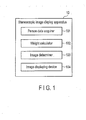
- a stereoscopic image display apparatus 10 comprises a person data acquiring unit 101, a weight calculating unit 102, an image determining unit 103, and an image displaying unit 104.
- the apparatus 10 can change the mode of displaying a stereoscopic image in accordance with the positions of viewers and can enable, for example, several viewers to see a good stereoscopic image at the same time.
- the person data acquiring unit 101 detects the positions of the viewers (hereinafter called "persons") who are viewing the stereoscopic image the stereoscopic image display apparatus 10 displays.
- This embodiment can cope with the case where several persons view an image, and can detect the position of each of these persons.
- the person data acquiring unit 101 outputs the person data representing the position detected of each person.
- a detecting unit such as a camera, may detect the position of a person i, thus finding the coordinates (hereinafter referred to as "position coordinates Xi, Yi") of the position that the person assumes with respect to the stereoscopic image display apparatus 10.
- the weight calculating unit 102 calculates a weight representing the stereoscopic degree for each person, from the person data acquired by the person data acquiring unit 101 and including the position of the person.
- the image determining unit 103 selects the display parameters at which the sum of weights the weight calculating unit 102 has calculated for each person is maximal, and outputs the multi-viewpoint image that accords with the display parameters selected.
- the image displaying unit 104 displays the multi-viewpoint image output from the image determining unit 103.
- the image displaying unit 104 is a device configured to display the multi-viewpoint image generated by the image determining unit 103.
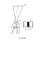
- the image displaying unit 104 comprises a display element array 114 and an aperture control unit 115 arranged in front of the display element array 114.
- a liquid crystal display (LCD) may be used as the display element array 114.
- the aperture control unit 115 is a light-beam control element that controls the light beams being transmitted and guides the light beams in a prescribed direction.
- a lenticular sheet may be used as the aperture control unit 115.
- the lenticular sheet is an array plate of lens segments, which controls the input light beams and output light beams, guiding them in a prescribed direction.
- an array plate having slits, i.e., light-transmitting regions can be used as the aperture control unit 115.
- These light-transmitting regions and lens segments have a function of emitting those of the light beams emerging forwards from the display element array 114, which propagate in a specific direction.
- the lens segments and the light-transmitting regions will be collectively referred to as "optical aperture unit.”
- a lenticular sheet is used, which is a lens array used in the display element array 114, each lens having a genetratrix extending perpendicular to the screen.
- the optical apertures 116, 116, ... of the respective lens segments are arranged in association with pixels.
- the aperture control unit 115 is not limited to such a lenticular lens sheet as described above or an array plate composed of light-transmitting regions. Instead, an LCD can be used as a light shutter that can change the position and shape of each light-transmitting region.
- one pixel is composed of sub-pixels for red, green and blue (RGB), respectively.
- RGB red, green and blue
- the display element array 114 has display pixels (sub-pixels 140, 141, ...) arranged in the form of a matrix, each having an aspect ratio of 3:1 so that the pixel may be shaped like a square.
- Each sub-pixel emits red (R) light, green (G) light or blue (B) light.
- an image defined by sub-pixels arranged in the row direction, in the number associated with parallax, i.e., a set of parallax images represented by the sub-pixels associated with the exit pupil (i.e., optical aperture 116), shall be called “element image.”
- the sub-pixels are not limited to those for red, green and blue (RGB).
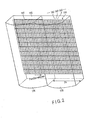
- the element image is composed of six sub-pixels arranged in the column direction. That is, one element image 141 is defined by 18 pixels arranged in the row direction and six pixels arranged in the column direction (as indicated by a frame in FIG. 2 ). As seen from FIG. 2 , a stereoscopic image can be displayed, which achieves 18 parallaxes in the horizontal direction, and the element image, i.e., pixels defining the stereoscopic image, becomes square because the six pixels are arranged in the column direction.
- the position any pixel assumes in one valid pixel in the horizontal direction corresponds to the aperture control unit 115, and is correlated to the angle at which a light beam is emitted.
- parallax address The address representing the direction of the light beam shall be called "parallax address.”
- the parallax address corresponds to the position the pixel assumes, in one valid pixel, with respect to the horizontal direction.
- the parallax address gradually increases toward the right edge of the screen.
- the optical apertures 116, 916, ... are arranged at the element images, respectively.
- the width Ps (lens pitch) of any optical aperture 116 is equal to the width of one element image.
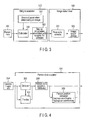
- FIG. 3 schematically shows the configurations of the weight calculating unit 102 and image determining unit 103.
- the weight calculating unit 102 has a calculating unit 300.
- the calculating unit 300 receives the person data 200 containing the data acquired by the person data acquiring unit 101 and representing the position of each person, and also receives parameters for determining images.
- the calculating unit 300 calculates the weight representing the stereoscopic degree for each person and outputs the weight about the person and the display parameter 203 associated with the weight.
- the weight W representing the stereoscopic degree has been calculated from the person data 200 for the multi-viewpoint image (i.e., combination of pixels) to display at the image display apparatus 10 and for the display parameters 201 related to the hardware design of the image display apparatus 10.
- the weight W which is based at least on the position of each person, may be changed in any manner. For example, it may be changed in accordance with any one of the viewing modes the viewer has selected.
- the objects that can be controlled in accordance with the display parameters, such as the arrangement of pixels to display, will be described later in detail.
- the weight (called “position weight”) is calculated, which accords with the area of stereoscopic display, the density of light beams and the position designated.
- the position data about each person should therefore be acquired by any means.
- a weight associated with the attribute of each person (hereinafter referred to as “attribute weight”) is calculated in addition to the position weight.
- the value of the position weight and that of the attribute weight are synthesized, generating the weight W.
- the image determining unit 103 comprises a parameter selecting unit 301 and an image output unit 302.
- the parameter selecting unit 301 receives the weight of each person and the display parameter 203 associated with this weight, and selects a display parameter that maximizes the total sum of the weights of persons, which the weight calculating unit 102 has calculated.
- the image output unit 302 outputs the multi-viewpoint image that accords with the display parameter selected by the parameter selecting unit 301.
- Fig. 4 shows the configuration of the person data acquiring unit 101.
- the person data acquiring unit 101 comprises a detecting unit 303 and a tracking unit 304.
- the detecting unit 303 receives a camera image 204 or the like, detects the position of each person, and outputs the person data 200 representing the position and attribute of each person.
- the tracking unit 304 detects the change in the position of the same person for a prescribed time, from the output of the detecting unit 303. That is, the tracking unit 304 tracks each person moving.
- the image used to detect the position is not limited to an image coming from a camera.
- a signal provided from, for example, radar may be used instead.
- Any object that can be recognized as pertaining to a person e.g., face, head, entire person or marker, may be detected in order to detect the position.
- the attribute of each person the name, child/adult distinction, viewing time, remote controller ownership, or the like can be exemplified.
- the attribute is detected by any means or by may be explicitly input by the viewer or someone else.
- the person data acquiring unit 101 may further comprise a person position converting unit 305 configured to convert the position data about each person, to a coordinate value.
- the person position converting unit 305 may be provided not in the person data acquiring unit 101, but in the weight calculating unit 102.
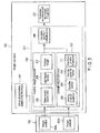
- FIG. 5 shows the configuration of the weight calculating unit 102.
- the weight calculating unit 102 comprises the calculating unit 300.
- the calculating unit 300 receives the person data 200 and a parameter group that determines an image and calculates and outputs the weight of each person and the display parameter 203 associated with this weight.
- the calculating unit 300 comprises a position weight calculating unit 306, an attribute weight calculating unit 307, and a calculating unit 308.
- the position weight calculating unit 306 calculates a position weight from the parameter group that determines the person position 204 and the image.
- the attribute weight calculating unit 307 calculates an attribute weight from the person attribute 205.
- the calculating unit 308 calculates the sum or product of the position weight and the attribute weight, so calculated. If only the position weight or the attribute weight is utilized, the sum or product of these weights need not be calculated.
- the position weight calculating unit 306 calculates the position weight from stereoscopic display area 205, light beam density 206 and position weight 207 designated.
- the stereoscopic display area 205 is determined from the position of each person (i.e., position relative to the display screen of the image display apparatus 10) and the multi-viewpoint image. The larger this area, the greater the position weight will be.
- the light beam density 206 is determined from the distance from the display screen of the image display apparatus 10 and the number of viewpoints. The higher the light beam density 206, the greater the position weight will become.
- a greater weight is assigned to the usual viewing position than to any other positions.
- the position weight calculating unit 306 calculates the sum or product of the weights calculated for the stereoscopic display area 205, light beam density 206 and position weight 207, and outputs the sum or product. Only one of these weights may be utilized. In this case, the sum or product of these weights need not be calculated. Moreover, any other item that can represent a weight pertaining to a "viewed state" may be added.
- the attribute weight calculating unit 307 calculates the attribute weight from attribute values such as the viewing time or a start sequence 208 and a specified person 209, the remote controller holder 210 and the positional relation 211 of the persons. Higher weights are assigned to the viewing time and start sequence 208 so that any person who has been viewing for a long time or has started viewing before anyone else may have priority. Similarly, the weight for the specified person 209 or holder 210 of the remote controller is increased so that the specified person 209 or holder 210 may have priority. As for the positional relation 211, a person sitting in front of the display or near the display has a greater weight than any other persons.
- the attribute weight calculating unit 307 finds the sum or product of the weights calculated for the viewing time and start sequence 208, specified person 209, remote controller holder 210 and positional relation 211, and outputs the sum or product. If only one of these weights is utilized, the sum or product of these weights need not be calculated. Further, any other item that can represent a weight pertaining to viewing may be added.
- the calculating unit 308 calculates the sum or product of the weight value output from the position weight calculating unit 306 and the attribute weight value output from the attribute weight calculating unit 307.
- the calculating unit 308 must calculate at least the position weight.
- the weight is calculated for each person with respect to each of the display parameters included in the display parameters 201 that determine the image. As a rule, weights are calculated for all persons (except for the case where the parameters are selected for the specified person 209 only).
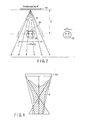
- a "viewed state” can be geometrically found or calculated.
- the pattern 21 extracted at a view region setting distance by the two lines connecting a person 20 to the two edges of the image displaying unit (display) 104, is identical to the "viewed state.”
- the parts 22 of the pattern 21 are regions in which no stereoscopic views can be seen.
- the ratio of these parts 22 to the entire pattern 21 can be calculated as a weight.
- the ratio of the parts 22 may be, for example, 100%.
- the entire pattern 21 is seen as a stereoscopic image, and the weight calculated has the maximum value of, for example, "1.”
- the ratio of the width len of the light beam to the inter-eye distance d is regarded as the weight of the light beam density 206. If the width len of the light beam is smaller than the inter-eye distance d, the weight of the light beam density 206 will be set to the value of "1.”
- FIG. 8 shows an exemplary weight map M, in which the weight value calculated by the calculated by the weight calculating unit 102 are distributed in the real-space coordinates.
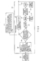
- FIG. 9 shows the configuration of the image determining unit 103.
- the image determining unit 103 receives the weight of each person, output from the weight calculating unit, and also the display parameter 203 associated with this weight.
- the weight of each person and the display parameter may be either a single output or a plurality of outputs. It the image determining unit 103 receives a single output, the output may be the maximum total value of weights for each person, the maximum value for the specified person, or the average value or intermediate value for each person, which is greater than the other.
- different priorities may be allocated to the viewers in accordance with their attribute weights, and the maximum value of the total weight for the viewers having priorities higher than a specific value, or the average or intermediate value of the weights for the viewers, which is greater than the other.
- the decision unit 310 of the image determining unit 103 determines whether the weight described above is equal to or greater than a prescribed reference value. If the decision unit 310 receives a plurality of outputs, it determines whether the weights of all viewers (or N viewer or more viewers) are equal to or greater than the reference value. Instead, different priorities may be allocated to the viewers in accordance with their attribute weights, and the decision unit 310 may determine whether the weights of only the viewers having priorities are higher than a particular value. In either case, a display parameter 213 associated with any weight equal to or greater than the reference value is selected.
- the image determining unit 103 may have a blend/section unit 311 that switches images if the scene changes so fast or the image moves so fast that the change can hardly be recognized.
- the image determining unit 103 may further have a blend/selection unit 312 that blends a multi-viewpoint image (stereoscopic image) 215 with an image 216 displayed in the past, thereby slowing changing the scene. In the process of blending the images, it is desired that a primary delay should be absorbed.
- the presentation of the multi-viewpoint image (stereoscopic image) that accords with the selected display parameter can be achieved by physically changing the position or orientation of the display 104 as will be described later.
- an image 212 such as a two-dimensional image, monochromic image, black image (not displayed) or colorless image, will be displayed (that is, a 2D image is displayed), in order not to display an inappropriate stereoscopic image.
- the 2D image will be displayed if the total sum of weights is too small, if some of the viewers are unable to see the stereoscopic image, or if the visibility is too low for the specified person.
- the image determining unit 103 may further have a data display unit 311 that guides any person to a position where he or she can see the stereoscopic image or generates an alarm informing any person that he or she can not see the stereoscopic image.
- the controls achieved by the display parameter 201 that determine an image will be explained. Some of the display parameters control the view region, and the other display parameters control the light beam density.
- the parameters for controlling the view region are the image shift, the pixel pitch, the gap between each lens segment and the pixel associated therewith, and the rotation, deforming and motion of the display.
- the parameters for controlling the light beam density are the gap between the each lens segment and the pixel associated therewith and the parallax number.
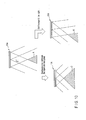
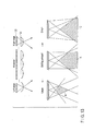
- the display parameters for controlling the view region will be explained with reference to FIG. 10 and FIG. 11 . If the image displayed is shifted to, for example, the right, the "view region," i.e., region where the stereoscopic image can be seen well, will move from region A to region B, as shown in FIG. 10 . As seen from the comparison items (a) and (c) shown in FIG. 11 , the view region shifts to the left, or moves to region B, because the light beam L shifts to the left as shown at item (c).
- the view region will move from region A to region C, as can be understood by comparing items (a) and (b) shown in FIG. 11 . In this case, the light beam density decreases, though the view region gets nearer.
- parallax images are sequentially arranged at the pixels 22 of the display in a specific order.
- the parallax images are images, each deviating from the view point. They are equivalent to the images of a person 20, photographed with a plurality of cameras 21, respectively, as shown in FIG. 11 .
- the light beam emerging from the pixel 22 (sub-pixel 140) emerges, passing through the lens/slit 23 (optical aperture 116).
- the shape of the view region can be geometrically determined, by using angles ⁇ and ⁇ shown in FIG. 11 .
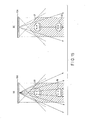
- the adjacent view regions will be explained with reference to FIG. 12 .
- the view region B adjacent to view region A in which the image is viewed is defined by the left pixel and the lens on the right side of the leftmost lens and the pixel and by the right pixel and the lens on the left side of the rightmost lens.
- the view region B can be further shifted to the left or the right.
- the view region can be better controlled by shifting the pixel 22 and the lens 23 relative to each other. If the pixel 22 and the lens 23 are much shifted relative to each other, the view region will change from view region A to the view region B as shown in FIG. 13 . Conversely, if the pixel 22 and the lens 23 are shifted relative a little to each other, the view region will change from view region A to the view region C as shown in FIG. 13 .
- the width and nearness of the view region can thus be controlled in accordance with the display parameter related to the pixel arrangement (pixel pitch). The distance at which the view region is broadest shall be called "view-region setting distance.”
- the view region is controlled by moving, rotating or deforming the image displaying unit.
- the basic view region A can be changed to view region B by rotating the image displaying unit 104.
- the basic view region A can be changed to view region C by moving the image displaying unit 104, and to view region D by deforming the image displaying unit 104.
- the view region can be controlled by moving, rotating or deforming the image displaying unit 104, thereby controlling the view region.
- the parallax number is 6 as shown in item (a) of FIG. 15 , the person 31 closer to the display 104 than the person 30 receives more light beams and can therefore see a better stereoscopic image than the person 30.
- the parallax number is 3 as shown in item (b) of FIG. 15 , reducing the light beam density, the person 31 receives less light beams than in the case shown in item (a) of FIG. 15 so long as the person remains at the same distance from the display 104.
- the density of the light beams emitted from each pixel of the display 104 can be calculated from the angle ⁇ determined by the lens and the gap, the parallax number and the position of the person.
Landscapes
- Physics & Mathematics (AREA)
- Engineering & Computer Science (AREA)
- General Physics & Mathematics (AREA)
- Multimedia (AREA)
- Signal Processing (AREA)
- Optics & Photonics (AREA)
- Computer Hardware Design (AREA)
- Theoretical Computer Science (AREA)
- Testing, Inspecting, Measuring Of Stereoscopic Televisions And Televisions (AREA)
- Controls And Circuits For Display Device (AREA)
- Processing Or Creating Images (AREA)
Applications Claiming Priority (1)
| Application Number | Priority Date | Filing Date | Title |
|---|---|---|---|
| PCT/JP2010/070815 WO2012070103A1 (ja) | 2010-11-22 | 2010-11-22 | 立体画像表示装置および方法 |
Publications (2)
| Publication Number | Publication Date |
|---|---|
| EP2495984A1 true EP2495984A1 (de) | 2012-09-05 |
| EP2495984A4 EP2495984A4 (de) | 2013-11-20 |
Family
ID=46145480
Family Applications (1)
| Application Number | Title | Priority Date | Filing Date |
|---|---|---|---|
| EP10855122.7A Withdrawn EP2495984A4 (de) | 2010-11-22 | 2010-11-22 | Vorrichtung und verfahren zur anzeige stereoskopischer bilder |
Country Status (8)
| Country | Link |
|---|---|
| US (1) | US20120182292A1 (de) |
| EP (1) | EP2495984A4 (de) |
| JP (1) | JP4937424B1 (de) |
| KR (1) | KR101292513B1 (de) |
| CN (1) | CN102668576B (de) |
| RU (1) | RU2012104001A (de) |
| TW (1) | TWI507013B (de) |
| WO (1) | WO2012070103A1 (de) |
Families Citing this family (16)
| Publication number | Priority date | Publication date | Assignee | Title |
|---|---|---|---|---|
| JP5110182B2 (ja) * | 2011-03-11 | 2012-12-26 | オムロン株式会社 | 映像表示装置 |
| JP2013182209A (ja) * | 2012-03-02 | 2013-09-12 | Toshiba Corp | 立体画像表示装置、立体画像表示方法、および制御装置 |
| JP5727969B2 (ja) | 2012-06-15 | 2015-06-03 | 株式会社東芝 | 位置推定装置、方法、及びプログラム |
| JP6099892B2 (ja) * | 2012-07-09 | 2017-03-22 | パナソニック インテレクチュアル プロパティ コーポレーション オブ アメリカPanasonic Intellectual Property Corporation of America | 映像表示装置 |
| CN103595997A (zh) * | 2012-08-13 | 2014-02-19 | 辉达公司 | 3d显示系统和3d显示方法 |
| TWI524736B (zh) * | 2012-11-20 | 2016-03-01 | 群康科技(深圳)有限公司 | 三維影像顯示系統及其校正方法 |
| US9674510B2 (en) * | 2012-11-21 | 2017-06-06 | Elwha Llc | Pulsed projection system for 3D video |
| JP5810247B2 (ja) * | 2013-10-08 | 2015-11-11 | オリンパス株式会社 | 立体視内視鏡システム |
| CN106297610B (zh) | 2015-06-05 | 2020-03-17 | 北京智谷睿拓技术服务有限公司 | 显示控制方法和装置 |
| CN106297611B (zh) * | 2015-06-05 | 2021-08-10 | 北京智谷睿拓技术服务有限公司 | 显示控制方法和装置 |
| CN106291953B (zh) | 2015-06-05 | 2019-01-08 | 北京智谷睿拓技术服务有限公司 | 显示控制方法和装置 |
| KR102415502B1 (ko) * | 2015-08-07 | 2022-07-01 | 삼성전자주식회사 | 복수의 사용자를 위한 라이트 필드 렌더링 방법 및 장치 |
| JP6131312B2 (ja) * | 2015-12-08 | 2017-05-17 | 株式会社Pfu | 情報処理装置、方法およびプログラム |
| CN108234990B (zh) * | 2018-02-12 | 2021-04-20 | 苏州佳世达电通有限公司 | 立体显示设备及立体显示方法 |
| US11243410B2 (en) * | 2019-04-26 | 2022-02-08 | Wuhan Tianma Micro-Electronics Co., Ltd. | Display device |
| JP7516781B2 (ja) * | 2020-03-04 | 2024-07-17 | 富士フイルムビジネスイノベーション株式会社 | 表示システム、表示制御装置及びプログラム |
Family Cites Families (18)
| Publication number | Priority date | Publication date | Assignee | Title |
|---|---|---|---|---|
| JPH0389794A (ja) * | 1989-09-01 | 1991-04-15 | Nippon Telegr & Teleph Corp <Ntt> | 多人数用三次元表示方式 |
| DE4312918A1 (de) * | 1993-04-14 | 1994-10-20 | Hertz Inst Heinrich | Wiedergabeeinrichtung |
| DE69434685T2 (de) * | 1993-08-04 | 2006-09-14 | Canon K.K. | Bildverarbeitungsverfahren und -gerät |
| JP2812254B2 (ja) * | 1995-05-31 | 1998-10-22 | 日本電気株式会社 | 視点追従型立体映像表示装置 |
| US6005607A (en) * | 1995-06-29 | 1999-12-21 | Matsushita Electric Industrial Co., Ltd. | Stereoscopic computer graphics image generating apparatus and stereoscopic TV apparatus |
| JP3514947B2 (ja) * | 1997-06-05 | 2004-04-05 | シャープ株式会社 | 3次元画像処理装置及び3次元画像処理方法 |
| JPH11155152A (ja) * | 1997-11-21 | 1999-06-08 | Canon Inc | 三次元形状情報入力方法及び装置及び画像入力装置 |
| US6757422B1 (en) * | 1998-11-12 | 2004-06-29 | Canon Kabushiki Kaisha | Viewpoint position detection apparatus and method, and stereoscopic image display system |
| JP2001319217A (ja) * | 2000-05-09 | 2001-11-16 | Fuji Photo Film Co Ltd | 画像表示方法 |
| US6677982B1 (en) * | 2000-10-11 | 2004-01-13 | Eastman Kodak Company | Method for three dimensional spatial panorama formation |
| KR100416548B1 (ko) * | 2001-10-10 | 2004-02-05 | 삼성전자주식회사 | 3차원 영상 표시장치 |
| US8369607B2 (en) * | 2002-03-27 | 2013-02-05 | Sanyo Electric Co., Ltd. | Method and apparatus for processing three-dimensional images |
| KR100977193B1 (ko) * | 2002-04-25 | 2010-08-20 | 샤프 가부시키가이샤 | 화상 데이터 생성 장치, 화상 데이터 재생 장치, 및 화상데이터 기록 매체 |
| US7084904B2 (en) * | 2002-09-30 | 2006-08-01 | Microsoft Corporation | Foveated wide-angle imaging system and method for capturing and viewing wide-angle images in real time |
| JP4440067B2 (ja) | 2004-10-15 | 2010-03-24 | キヤノン株式会社 | 立体表示のための画像処理プログラム、画像処理装置および立体表示システム |
| JP2009077234A (ja) * | 2007-09-21 | 2009-04-09 | Toshiba Corp | 三次元画像処理装置、方法及びプログラム |
| KR101502603B1 (ko) * | 2008-09-22 | 2015-03-13 | 삼성전자주식회사 | 입체 영상 표시 장치 및 그 방법 |
| TWI387316B (zh) * | 2008-11-18 | 2013-02-21 | 財團法人工業技術研究院 | 立體影像顯示裝置與立體影像顯示方法 |
-
2010
- 2010-11-22 JP JP2011546354A patent/JP4937424B1/ja not_active Expired - Fee Related
- 2010-11-22 WO PCT/JP2010/070815 patent/WO2012070103A1/ja not_active Ceased
- 2010-11-22 CN CN201080026723.9A patent/CN102668576B/zh not_active Expired - Fee Related
- 2010-11-22 KR KR1020117030074A patent/KR101292513B1/ko not_active Expired - Fee Related
- 2010-11-22 EP EP10855122.7A patent/EP2495984A4/de not_active Withdrawn
- 2010-11-22 RU RU2012104001/08A patent/RU2012104001A/ru unknown
-
2011
- 2011-11-22 TW TW100142724A patent/TWI507013B/zh not_active IP Right Cessation
-
2012
- 2012-01-30 US US13/361,148 patent/US20120182292A1/en not_active Abandoned
Also Published As
| Publication number | Publication date |
|---|---|
| KR101292513B1 (ko) | 2013-08-01 |
| US20120182292A1 (en) | 2012-07-19 |
| TWI507013B (zh) | 2015-11-01 |
| JPWO2012070103A1 (ja) | 2014-05-19 |
| KR20120069612A (ko) | 2012-06-28 |
| CN102668576A (zh) | 2012-09-12 |
| JP4937424B1 (ja) | 2012-05-23 |
| CN102668576B (zh) | 2015-09-02 |
| TW201236441A (en) | 2012-09-01 |
| WO2012070103A1 (ja) | 2012-05-31 |
| RU2012104001A (ru) | 2014-12-27 |
| EP2495984A4 (de) | 2013-11-20 |
Similar Documents
| Publication | Publication Date | Title |
|---|---|---|
| EP2495984A1 (de) | Vorrichtung und verfahren zur anzeige stereoskopischer bilder | |
| KR101290908B1 (ko) | 3차원 영상 표시 장치 | |
| US8310524B2 (en) | Stereoscopic image display apparatus | |
| JP3966830B2 (ja) | 立体表示装置 | |
| US8531454B2 (en) | Display apparatus and stereoscopic image display method | |
| JP5631329B2 (ja) | 立体映像表示装置、立体映像表示方法 | |
| US8681174B2 (en) | High density multi-view image display system and method with active sub-pixel rendering | |
| US20120062556A1 (en) | Three-dimensional image display apparatus, three-dimensional image processor, three-dimensional image display method, and computer program product | |
| US20120194905A1 (en) | Image display apparatus and image display method | |
| KR20140073584A (ko) | 화상 처리 장치, 입체 화상 표시 장치, 화상 처리 방법 및 화상 처리 프로그램 | |
| US20140192168A1 (en) | Image processing device, method, and stereoscopic image display device | |
| KR100742728B1 (ko) | 3차원 화상 표시장치 | |
| CN105230012B (zh) | 用于再生图像信息的方法和自动立体屏幕 | |
| JP4977278B1 (ja) | 画像処理装置、立体画像表示装置および画像処理方法 | |
| US20130229336A1 (en) | Stereoscopic image display device, stereoscopic image display method, and control device | |
| US8368744B2 (en) | Image display apparatus, image processing device, and image processing method | |
| US20140362197A1 (en) | Image processing device, image processing method, and stereoscopic image display device | |
| JP5422684B2 (ja) | 立体画像決定装置、立体画像決定方法、および立体画像表示装置 | |
| JP2002305759A (ja) | 眼鏡無し立体映像表示装置 |
Legal Events
| Date | Code | Title | Description |
|---|---|---|---|
| PUAI | Public reference made under article 153(3) epc to a published international application that has entered the european phase |
Free format text: ORIGINAL CODE: 0009012 |
|
| 17P | Request for examination filed |
Effective date: 20120127 |
|
| AK | Designated contracting states |
Kind code of ref document: A1 Designated state(s): AL AT BE BG CH CY CZ DE DK EE ES FI FR GB GR HR HU IE IS IT LI LT LU LV MC MK MT NL NO PL PT RO RS SE SI SK SM TR |
|
| RIC1 | Information provided on ipc code assigned before grant |
Ipc: G09G 5/36 20060101ALI20130301BHEP Ipc: G02B 27/22 20060101ALI20130301BHEP Ipc: H04N 13/04 20060101AFI20130301BHEP Ipc: G09G 5/00 20060101ALI20130301BHEP |
|
| A4 | Supplementary search report drawn up and despatched |
Effective date: 20131018 |
|
| RIC1 | Information provided on ipc code assigned before grant |
Ipc: G09G 3/00 20060101ALI20131014BHEP Ipc: G02B 27/22 20060101ALI20131014BHEP Ipc: G09G 5/36 20060101ALI20131014BHEP Ipc: H04N 13/04 20060101AFI20131014BHEP Ipc: G09G 5/00 20060101ALI20131014BHEP |
|
| DAX | Request for extension of the european patent (deleted) | ||
| STAA | Information on the status of an ep patent application or granted ep patent |
Free format text: STATUS: THE APPLICATION HAS BEEN WITHDRAWN |
|
| 18W | Application withdrawn |
Effective date: 20160119 |