EP2495540A2 - Design von Filtermodulen für öffnungskodierte Multiplex-Bildgebungssysteme - Google Patents
Design von Filtermodulen für öffnungskodierte Multiplex-Bildgebungssysteme Download PDFInfo
- Publication number
- EP2495540A2 EP2495540A2 EP12157955A EP12157955A EP2495540A2 EP 2495540 A2 EP2495540 A2 EP 2495540A2 EP 12157955 A EP12157955 A EP 12157955A EP 12157955 A EP12157955 A EP 12157955A EP 2495540 A2 EP2495540 A2 EP 2495540A2
- Authority
- EP
- European Patent Office
- Prior art keywords
- filter
- modifying
- candidate
- spatial partition
- filter module
- Prior art date
- Legal status (The legal status is an assumption and is not a legal conclusion. Google has not performed a legal analysis and makes no representation as to the accuracy of the status listed.)
- Granted
Links
- 238000003384 imaging method Methods 0.000 title claims abstract description 45
- 238000013461 design Methods 0.000 title claims description 23
- 238000005192 partition Methods 0.000 claims abstract description 67
- 238000000034 method Methods 0.000 claims abstract description 27
- 230000003595 spectral effect Effects 0.000 claims description 43
- 230000003287 optical effect Effects 0.000 claims description 28
- 230000004044 response Effects 0.000 claims description 27
- 238000009826 distribution Methods 0.000 description 24
- 238000005457 optimization Methods 0.000 description 24
- 230000004075 alteration Effects 0.000 description 10
- 238000013459 approach Methods 0.000 description 9
- 238000001514 detection method Methods 0.000 description 9
- 239000011159 matrix material Substances 0.000 description 9
- 238000003491 array Methods 0.000 description 8
- 230000000694 effects Effects 0.000 description 8
- 238000005259 measurement Methods 0.000 description 6
- 238000010586 diagram Methods 0.000 description 5
- 238000001914 filtration Methods 0.000 description 5
- 238000012546 transfer Methods 0.000 description 4
- 230000005540 biological transmission Effects 0.000 description 3
- 230000015572 biosynthetic process Effects 0.000 description 3
- 238000000701 chemical imaging Methods 0.000 description 3
- 230000010354 integration Effects 0.000 description 3
- 238000012986 modification Methods 0.000 description 3
- 230000004048 modification Effects 0.000 description 3
- 238000012634 optical imaging Methods 0.000 description 3
- 230000010287 polarization Effects 0.000 description 3
- 238000012360 testing method Methods 0.000 description 3
- 101100193720 Caenorhabditis elegans rbg-1 gene Proteins 0.000 description 2
- 239000002131 composite material Substances 0.000 description 2
- 230000001902 propagating effect Effects 0.000 description 2
- 238000005316 response function Methods 0.000 description 2
- 230000035945 sensitivity Effects 0.000 description 2
- 230000000007 visual effect Effects 0.000 description 2
- XUIMIQQOPSSXEZ-UHFFFAOYSA-N Silicon Chemical compound [Si] XUIMIQQOPSSXEZ-UHFFFAOYSA-N 0.000 description 1
- 230000008859 change Effects 0.000 description 1
- 238000011156 evaluation Methods 0.000 description 1
- 238000002474 experimental method Methods 0.000 description 1
- 238000012632 fluorescent imaging Methods 0.000 description 1
- 238000003780 insertion Methods 0.000 description 1
- 230000037431 insertion Effects 0.000 description 1
- 238000004519 manufacturing process Methods 0.000 description 1
- 238000010606 normalization Methods 0.000 description 1
- 238000012545 processing Methods 0.000 description 1
- 230000000644 propagated effect Effects 0.000 description 1
- 238000000985 reflectance spectrum Methods 0.000 description 1
- 238000005070 sampling Methods 0.000 description 1
- 229910052710 silicon Inorganic materials 0.000 description 1
- 239000010703 silicon Substances 0.000 description 1
- 238000000638 solvent extraction Methods 0.000 description 1
- 238000001228 spectrum Methods 0.000 description 1
- 238000010183 spectrum analysis Methods 0.000 description 1
- 239000000126 substance Substances 0.000 description 1
- 230000009466 transformation Effects 0.000 description 1
Images


Classifications
-
- G—PHYSICS
- G01—MEASURING; TESTING
- G01J—MEASUREMENT OF INTENSITY, VELOCITY, SPECTRAL CONTENT, POLARISATION, PHASE OR PULSE CHARACTERISTICS OF INFRARED, VISIBLE OR ULTRAVIOLET LIGHT; COLORIMETRY; RADIATION PYROMETRY
- G01J3/00—Spectrometry; Spectrophotometry; Monochromators; Measuring colours
- G01J3/02—Details
- G01J3/0205—Optical elements not provided otherwise, e.g. optical manifolds, diffusers, windows
- G01J3/0208—Optical elements not provided otherwise, e.g. optical manifolds, diffusers, windows using focussing or collimating elements, e.g. lenses or mirrors; performing aberration correction
-
- G—PHYSICS
- G06—COMPUTING; CALCULATING OR COUNTING
- G06F—ELECTRIC DIGITAL DATA PROCESSING
- G06F30/00—Computer-aided design [CAD]
- G06F30/20—Design optimisation, verification or simulation
-
- G—PHYSICS
- G01—MEASURING; TESTING
- G01J—MEASUREMENT OF INTENSITY, VELOCITY, SPECTRAL CONTENT, POLARISATION, PHASE OR PULSE CHARACTERISTICS OF INFRARED, VISIBLE OR ULTRAVIOLET LIGHT; COLORIMETRY; RADIATION PYROMETRY
- G01J1/00—Photometry, e.g. photographic exposure meter
- G01J1/02—Details
- G01J1/04—Optical or mechanical part supplementary adjustable parts
- G01J1/0488—Optical or mechanical part supplementary adjustable parts with spectral filtering
- G01J1/0492—Optical or mechanical part supplementary adjustable parts with spectral filtering using at least two different filters
-
- G—PHYSICS
- G01—MEASURING; TESTING
- G01J—MEASUREMENT OF INTENSITY, VELOCITY, SPECTRAL CONTENT, POLARISATION, PHASE OR PULSE CHARACTERISTICS OF INFRARED, VISIBLE OR ULTRAVIOLET LIGHT; COLORIMETRY; RADIATION PYROMETRY
- G01J3/00—Spectrometry; Spectrophotometry; Monochromators; Measuring colours
- G01J3/02—Details
- G01J3/0205—Optical elements not provided otherwise, e.g. optical manifolds, diffusers, windows
- G01J3/0229—Optical elements not provided otherwise, e.g. optical manifolds, diffusers, windows using masks, aperture plates, spatial light modulators or spatial filters, e.g. reflective filters
-
- G—PHYSICS
- G01—MEASURING; TESTING
- G01J—MEASUREMENT OF INTENSITY, VELOCITY, SPECTRAL CONTENT, POLARISATION, PHASE OR PULSE CHARACTERISTICS OF INFRARED, VISIBLE OR ULTRAVIOLET LIGHT; COLORIMETRY; RADIATION PYROMETRY
- G01J3/00—Spectrometry; Spectrophotometry; Monochromators; Measuring colours
- G01J3/28—Investigating the spectrum
- G01J3/2823—Imaging spectrometer
-
- G—PHYSICS
- G01—MEASURING; TESTING
- G01J—MEASUREMENT OF INTENSITY, VELOCITY, SPECTRAL CONTENT, POLARISATION, PHASE OR PULSE CHARACTERISTICS OF INFRARED, VISIBLE OR ULTRAVIOLET LIGHT; COLORIMETRY; RADIATION PYROMETRY
- G01J3/00—Spectrometry; Spectrophotometry; Monochromators; Measuring colours
- G01J3/28—Investigating the spectrum
- G01J3/30—Measuring the intensity of spectral lines directly on the spectrum itself
- G01J3/36—Investigating two or more bands of a spectrum by separate detectors
-
- G—PHYSICS
- G01—MEASURING; TESTING
- G01J—MEASUREMENT OF INTENSITY, VELOCITY, SPECTRAL CONTENT, POLARISATION, PHASE OR PULSE CHARACTERISTICS OF INFRARED, VISIBLE OR ULTRAVIOLET LIGHT; COLORIMETRY; RADIATION PYROMETRY
- G01J4/00—Measuring polarisation of light
-
- G—PHYSICS
- G02—OPTICS
- G02B—OPTICAL ELEMENTS, SYSTEMS OR APPARATUS
- G02B5/00—Optical elements other than lenses
- G02B5/20—Filters
- G02B5/201—Filters in the form of arrays
-
- G—PHYSICS
- G02—OPTICS
- G02B—OPTICAL ELEMENTS, SYSTEMS OR APPARATUS
- G02B5/00—Optical elements other than lenses
- G02B5/30—Polarising elements
- G02B5/3025—Polarisers, i.e. arrangements capable of producing a definite output polarisation state from an unpolarised input state
-
- H—ELECTRICITY
- H04—ELECTRIC COMMUNICATION TECHNIQUE
- H04N—PICTORIAL COMMUNICATION, e.g. TELEVISION
- H04N25/00—Circuitry of solid-state image sensors [SSIS]; Control thereof
- H04N25/10—Circuitry of solid-state image sensors [SSIS]; Control thereof for transforming different wavelengths into image signals
- H04N25/11—Arrangement of colour filter arrays [CFA]; Filter mosaics
- H04N25/13—Arrangement of colour filter arrays [CFA]; Filter mosaics characterised by the spectral characteristics of the filter elements
- H04N25/134—Arrangement of colour filter arrays [CFA]; Filter mosaics characterised by the spectral characteristics of the filter elements based on three different wavelength filter elements
-
- G—PHYSICS
- G01—MEASURING; TESTING
- G01J—MEASUREMENT OF INTENSITY, VELOCITY, SPECTRAL CONTENT, POLARISATION, PHASE OR PULSE CHARACTERISTICS OF INFRARED, VISIBLE OR ULTRAVIOLET LIGHT; COLORIMETRY; RADIATION PYROMETRY
- G01J3/00—Spectrometry; Spectrophotometry; Monochromators; Measuring colours
- G01J3/02—Details
- G01J3/0205—Optical elements not provided otherwise, e.g. optical manifolds, diffusers, windows
- G01J3/0224—Optical elements not provided otherwise, e.g. optical manifolds, diffusers, windows using polarising or depolarising elements
-
- G—PHYSICS
- G02—OPTICS
- G02B—OPTICAL ELEMENTS, SYSTEMS OR APPARATUS
- G02B2207/00—Coding scheme for general features or characteristics of optical elements and systems of subclass G02B, but not including elements and systems which would be classified in G02B6/00 and subgroups
- G02B2207/129—Coded aperture imaging
-
- H—ELECTRICITY
- H04—ELECTRIC COMMUNICATION TECHNIQUE
- H04N—PICTORIAL COMMUNICATION, e.g. TELEVISION
- H04N23/00—Cameras or camera modules comprising electronic image sensors; Control thereof
- H04N23/50—Constructional details
- H04N23/55—Optical parts specially adapted for electronic image sensors; Mounting thereof
Definitions
- This invention relates generally to imaging systems that can capture multiple images of the same object simultaneously, for example images of different spectral or polarization components of the object.
- spectral imaging applications may use a single image camera in connection with a filter wheel.
- the filter wheel contains wavelength filters that correspond to the wavelength bands of interest. At any one time, only one of the wavelength filters is positioned in the imaging path and the camera captures the filtered image.
- the filter wheel rotates in order to switch from one wavelength filter to the next, with the camera capturing images one after another.
- the multispectral imaging is implemented in a time multiplexed manner.
- the resulting systems can be large and complicated.
- dispersive elements such as prisms or gratings.
- dispersive elements are used to spatially separate different wavelengths.
- the light is typically dispersed along one dimension of the detector array.
- the other dimension is used to capture one spatial dimension of the object.
- time multiplexing is introduced to capture the second spatial dimension, for example by scanning.
- a conventional RGB imaging device may be based on a detector array where red, green and blue filters are attached to each individual detector.
- the Bayer pattern is one common pattern for arranging these micro-filters on the detector array.
- one disadvantage of this approach is the increased cost and complexity of manufacturing. Because there is a one-to-one correspondence between micro-filters and detectors, and because the micro-filters are attached to the detectors, the micro-filters are the same size as the detectors, which is small. The many different small micro-filters must then be arranged into an array and aligned with the underlying detectors. This may be difficult, especially if a large number of different types of micro-filters are required. Another disadvantage is the lack of flexibility. Once the micro-filter array is attached to the detector array, it is difficult to change the micro-filter array.
- the present invention overcomes the limitations of the prior art by providing a computer-implemented method for designing filter modules used in multi-imaging systems.
- an "aperture-multiplexed" imaging system includes a sensor that captures multiplexed images of an object.
- the filter module is positioned approximately in a conjugate plane to the sensor to provide aperture coding of the multiplexed images.
- the aperture-multiplexed imaging system performs a predefined task.
- the filter module is designed as follows. A model of the object(s) to be imaged by the imaging system is received. A candidate design for the filter module is also received. The candidate design includes a candidate spatial partition of the filter module into filter cells.
- the multiplexed image formation by the imaging system is simulated.
- a performance metric is calculated. The performance metric is a function of the simulated multiplexed images and is selected to be indicative of the predefined task.
- the candidate spatial partition of filter cells is modified based on the calculated performance metric.
- crosstalk between different filter cells is reduced, for example reduced spectral crosstalk if the filter cells are wavelength filters.
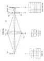
- FIGS 1A and 1B are diagrams illustrating an example aperture-multiplexed imaging system 110 according to the invention.
- the term "aperture-multiplexed" will be explained below.
- the system 110 includes an optical imaging group 112 and an array 114 of imaging-forming elements 115.
- the array 114 may be referred to as a microimaging array.
- the optical imaging group 112 is depicted in Figure 1A as a single objective lens, but it should be understood that it could contain multiple elements.
- the objective lens 112 forms an optical image 155 of the object 150 at an image plane IP.
- the microimaging array 114 is located at the image plane IP.
- the system in its entirety forms spatially multiplexed and interleaved optical images 170 at the sensor plane SP. Examples of microimaging arrays 114 include microlens arrays, arrays of pinholes, micromirror arrays, checkerboard grids and waveguide/channel arrays.
- the sensor array 180 is also shown in Figure 1A
- a filter module 125 is positioned at a plane SP' conjugate to the sensor plane SP.
- the actual physical location may be before, after or in the middle of the optical imaging group 112.
- the filter module contains a number of spatially multiplexed filter cells 127A-D.
- the filter module 125 includes a rectangular array of filter cells 127, as shown in the bottom portion of Figure 1A .
- the bottom portion of Figure 1A provides more detail.
- the object 150 is divided into a 3x3 array of regions, which are labeled 1-9.
- the filter module 125 is a 2x2 rectangular array of individual filter cells 127A-D.
- each filter cell 127A-D might have a different spectral response.
- the sensor array 180 is shown as a 6x6 rectangular array.
- Figure 1B illustrates conceptually how the spatially multiplexed optical images 170A-D are produced and interleaved at sensor array 180.
- the object 150 if captured and filtered by filter cell 127A, would produce an optical image 155A.
- the 3x3 regions are labeled with the suffix A: 1A-9A.
- the object 150 filtered by filter cells 127B,C,D would produce corresponding optical images 155B,C,D with 3x3 regions labeled 1B-9B, 1C-9C and 1D-9D.
- Each of these four optical images 155A-D is filtered by a different filter cell 127A-D within filter module 125 but they are all produced simultaneously by the imaging system 110.
- the four optical images 155A-D are formed in an interleaved fashion at the sensor plane, as shown in Figure 1B .
- image 155A as an example, the 3x3 regions 1A-9A from optical image 155A are not contiguous in a 3x3 block within optical image 170. Rather, regions 1A, 1B, 1C and 1D, from the four different optical images, are arranged in a 2x2 fashion in the upper left of optical image 170 (the inversion of image 170 is neglected for clarity). Regions 2-9 are similarly arranged. Thus, the regions 1A-9A that make up optical image 170A are spread out across the composite optical image 170, separated by portions of the other optical images 170B-D.
- the overall array can be divided into rectangular subarrays 171(1)-(9) of sensor elements (only one subarray 171(1) is shown in FIG. 1B ). For each region 1-9, all of the corresponding regions from each filtered image are imaged onto the subarray. For example, regions 1A, 1B, 1C and 1D are all imaged onto subarray 171(1).
- each imaging element 115 in array 114 forms an image of the filter module 125 at the sensor plane SP. Since there are multiple imaging elements 115, multiple images 171 of the filter module 125 are formed.
- Figure 1 has been simplified to illustrate underlying concepts.
- the object 150 was artificially divided into an array in order to more easily explain the overall imaging function.
- the invention is not limited to arrayed objects.
- most practical systems will use significantly larger arrays, particularly at the sensor assembly and possibly also at the filter module.
- Each region could correspond to multiple sensor elements, for example.
- the regions labeled 1 in the object, 1A in the filtered image 155A and 1A in the composite image 170 do not have to be exact images of each other.
- region 1A within image 170 may capture the filtered energy approximately from region 1 in the object 150, but it may not actually be an image of region 1.
- the energy collected by sensor elements in region 1A of image 170 may be integrating and sampling the image (or some transformation of the image) in region 1 in object 150, rather than representing a geometrical reproduction of the object at that region.
- effects such as parallax, vignetting, diffraction and optical propagation may affect any image formation.
- each captured image is filtered by a filter cell 127A-D within filter module 125, and each filter cell 127 may be designed to implement different filtering functions.
- the filter module 125 is located at a conjugate plane SP' rather than the actual sensor plane SP, and since this typically means that the filter module will be much larger compared to what would be required at the sensor plane, the tolerances and other mechanical requirements are relaxed. This makes it easier to manipulate the filter module, compared to if the filter module were located at the sensor plane (e.g., if attached to the sensor assembly).
- aperture-multiplexed refers to the fact that multiple images 170 are spatially multiplexed at the sensor 180 (in an interleaved fashion), and that each image 170 is filtered by a different filter cell 127A-D but the filtering is applied at the conjugate sensor plane (i.e., at the aperture) not at the actual sensor plane.
- system 110 is an "aperture-multiplexed" imaging system.
- the filtering which occurs at the aperture plane will sometimes be referred to as aperture coding.
- aperture coding One drawback of aperture coding is that the conjugate plane SP' typically will not be perfectly imaged onto the sensor plane SP. Effects such as distortion, parallax and aberrations (both geometric and chromatic) may cause crosstalk between adjacent multiplexed images at the sensor plane. Referring to Figure 1B , imperfect imaging may cause images 1A and 1B to blend together, at least at the boundaries. The net effect is that the blended image captured by the sensors 180 no longer represents the object filtered by only filter A or by only filter B, but as filtered by some combination of filters A and B. This crosstalk between filters A and B is usually undesirable.
- Figure 2 is a flow diagram for a method to design aperture-multiplexed imaging systems, which accounts for these system properties.
- the description 210 of the filter module has two parts: a spatial partition of the filter module into individual filter cells, and the optical properties (e.g., a specific spectral filter response or polarization filter response) of each filter cell.
- the purpose of the method in Figure 2 is to design the spatial partition and possibly also the individual optical properties.
- a computer system simulates 220 the overall image formation by the imaging system. This typically will include modeling the propagation through all of the optics, the detector behavior and subsequent processing. The modeling should be accurate enough to predict crosstalk between different filter cells.
- the resulting simulated images are used to calculate 230 a performance metric.
- the performance metric is selected according to the desired task for the imaging system. Steps 220 and 230 typically will also use models of the object(s) to be imaged, a description of the other portions of the imaging system and possibly also additional information about the task at hand.
- the filter module 210 is modified 240 based on the calculated performance metric. Repeating this cycle improves the design for the filter module.
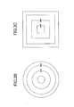
- FIGs 3A-4B illustrate various types of partitions and parameterizations.
- the filter module is partitioned into an array of rectangular filter cells, which are defined by their boundaries. The partition can be modified by moving the boundaries, as indicated by the arrows in the figure. For clarity, only a few arrows are shown in the figure. Note that the filter cells are all rectangular, but they need not be the same size.
- the filter module is partitioned into a concentric array of circular annular filter cells. This partition is also defined by the boundaries between filter cells. The boundaries are circles in this case.
- Figure 3C is a variation where the filter cells are square annular filter cells.
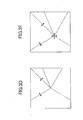
- the filter module is partitioned into a polar array of sector-shaped filter cells, again defined by the boundaries between filter cells.
- the outside border is shown as rectangular, but it could also be other shapes (e.g., circular).
- the position of the origin can also be changed.
- Figure 3E shows a sector-based partition, where the origin is offset from the center of the filter module.
- Figure 3F combines annular and sector boundaries, producing filter cells that have an annular sector shape. The annular boundaries and/or the sector boundaries can be modified.
- Figure 3G is similar, except that the sector boundaries can move independently for each annulus.
- Figures 3A-3G are all examples where the spatial partition is modified by moving boundaries between filter cells. This assumes that adjacent filter cells butt up against each other. This is not required.
- Figure 4A shows a partition of rectangular filter cells, where the boundary of each filter cell can be adjusted separately from the boundary of the adjacent filter cell. This can be used to create dead space or guard bands between filter cells, shown as the cross-hatched area in Figure 4A . Dead zones can be used beneficially to reduce crosstalk at the sensor.
- Figure 4B is a similar example using annular filter cells.
- the spatial partition of the filter module into filter cells can also be parameterized in other ways.
- the parameterization can be designed to permit modification of the position and/or size of filter cells within the filter module.
- Global modifications can also be made, for example scaling the entire filter module.
- the number of filter cells can also be variable.
- the optical properties for the filter cells may be determined a priori, in which case determining the spatial partition is the primary task in designing the filter module. An example might be if a certain spectral response is desired (e.g., detecting R, G and B components of an object, where the different components are defined by an industry standard).
- the optical properties for the filter cells may be iterated in addition to the spatial partitioning. The same is true for the rest of the imaging system. That is, in some cases, the rest of the imaging system (or certain components within the imaging system) may also be iterated based on the performance metric.
- the individual filter cells can have different shapes and sizes: rectangles, disk segments, rings, ring segments. Which one to choose depends in part on the application requirements. For example, an aperture mask coded with annuli has some advantages for extended depth of focus requirements. A partition into squares has some advantages in applications that require a compact point spread function at the microimaging array 114 to keep crosstalk between adjacent imaging elements to a minimum.
- the main lens system 112 has focal length F and diameter D .
- the microimaging array 114 is a microlens array, where each microlens has focal length f and diameter d .
- the distance from main lens 112 to microimaging array 114 is z 1 and the distance between microlens array 114 and sensor 180 is z 2 .
- the coordinates in the aperture plane SP' are denoted by u, v, those in the microlens plane IP by x, y, and those in the sensor plane SP by ⁇ , ⁇ .
- the filter module is described by a partition P of the filter module into a set of non-overlapping filter cells.
- Crosstalk at the MLA plane can be characterized as follows.
- the light passing through the main lens should ideally come to focus at the MLA plane. Due to lens aberrations and chromatic aberrations, that ideal case may not be achieved.
- Point spread functions (PSFs) for some wavelengths may have a larger width than PSFs for other wavelength and can leak over to other microlenses, causing crosstalk at the MLA plane.
- PSFs Point spread functions
- Spectral crosstalk at the sensor can then be characterized as follows.
- the image of the aperture mask on the sensor is not simply the same image scaled by the magnification factor of the microlens.
- Chromatic aberration, diffraction effects, and lens aberrations are distorting the image causing non-overlapping cells in the aperture mask to overlap in the sensor image.
- Such overlap causes spectral cross-talk at the sensor plane. Therefore, not an entire cell area, but a reduced one may contain the object's spectral information intended to be filtered.
- ⁇ 1 ⁇ i ⁇ j , i ⁇ j ⁇ ⁇ ⁇ ⁇ S
- ⁇ 2 S ⁇ ⁇ i ⁇ ⁇ ⁇ S
- the Bayer pattern contains twice as many green filters compared to red and blue since it is matching specific characteristics of the human visual system.
- a different distribution e.g. higher response in blue than red due to required discriminating power between signals in the blue and red region of the light spectrum.
- ⁇ is the Lebesgue measure.
- the information collected at the sensor should satisfy I ⁇ m ⁇ n I ⁇ n ⁇ ⁇ m .
- the difference between the distribution of captured spectral information and the target distribution is measure by a distance metric dist I ⁇ m ⁇ n I ⁇ n ⁇ ⁇ m .
- a light ray enters the system when the ray crosses the input plane at a distance x 1 from the optical axis while traveling in a direction that makes an angle ⁇ 1 with the optical axis. Some distance further along, the ray crosses the output plane, this time at a distance x 2 from the optical axis and making an angle ⁇ 2 .
- the focal length of a lens depends on the wavelength of the light passing through the lens. Typically lens specifications give the focal length as one number with respect to a reference wavelength. For other wavelengths, the focal properties differ a little, causing chromatic aberrations at the image plane. That means the ray transfer matrix U depends on ⁇ as f ⁇ and F ⁇ depend on ⁇ .
- Bayer Filtering Example Now consider a system designed to perform Bayer filtering, where the filter module is partitioned as shown in Figure 3B .
- the spectral responses for the filter cells are ⁇ 1 , ⁇ 2 , ⁇ 3 , respectively, each characterized by a center wavelength ⁇ 1 , ⁇ 2 , ⁇ 3 .
- ⁇ i we can compute the focal lengths f i and F i of microlens and main lens.
- the spatial extent of a disc of radius r imaged onto the sensor is given by 1 - z 2 f 1 ⁇ 1 - z 1 F i - z 2 F i ⁇ r . From the images of the ring radii for corresponding center wavelengths we can compute the overlap and wasted area between imaged rings.
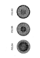
- Figures 5A-5C show three possible arrangements of red, green and blue filters within the filter module.
- the blue filter is in the center.
- Figures 5B and 5C are the two possible configurations where the red filter is in the center. These configurations will be referred to as BGR, RGB, and RBG, respectively.
- the filter cells are sized so that the G filter cell has twice the area of either the R or B filter cell, consistent with a standard Bayer configuration.
- the lens diameter ratio d / D 0.0325.
- Table 1 shows the radii of the image of each filter cell.
- Table 1 Radius of the images of the filter cells of Figure 5.
- BGR RGB RBG r o ,1 0.0164 0.0162 0.0162 r t ,2 0.0163 0.0163 0.0164 r o, 2 0.0282 0.0282 0.0232 r t ,3 0.0280 0.0284 0.0230 r o ,3 0.0323 0.0328 0.0326
- C Bayer max m - 1 , 2 , 3 ⁇ ⁇ m - 1 ⁇ area ⁇ 0 , g t pm ⁇ ⁇ 1 , g ⁇ ⁇ 2 , g ⁇ m area ⁇ 0 , g t pm ⁇ ⁇ 1 , g ⁇ ⁇ 2 , g - 1 .
- the two layouts BRG and RBG have the least amount of non-usable pixels on the sensor and preserve the target distribution of 1:2:1 best from among the six different layouts.
- all rays entering the main lens parallel to the optical axis hit the microlens. This does not have to be true in general.
- Wave Aberration Optics In order include diffraction effects and lens aberrations into the wave propagation computations to describe the wavefront passing through the aperture and the microlens onto the sensor, we approximate the diffraction integral by the Fresnel approximation using the operator notation introduced in J.W. Goodman, Introduction to Fourier Optics, McGraw-Hill, New York, 1986 .
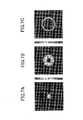
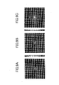
- the filter module uses the BGR configuration for the filter module ( Figure 5A ).
- Figure 6A shows the intensity distribution at the MLA plane, produced by light travelling through the blue filter cell (which is also assumed to have blue wavelength).
- Figures 6B and 6C show the intensity distributions at the MLA plane, produced by light travelling through the green and red filter cells, respectively.
- Figures 7A-7C show this same light but propagated to the sensor plane, assuming a non-aberrated microlens.
- Figure 7A shows the light distribution at the sensor plane, produced by light travelling through the blue filter cell.
- Figures 7B and 7C show the light distribution at the sensor plane, produced by light travelling through the green and red filter cells, respectively.
- Figures 9 and 10 are analogous figures, but using the RBG configuration ( Figure 5C ).
- Figure 9A is for the blue filter
- Figure 9B is for the green filter
- Figure 9C is for the red filter.
- the wavelengths are presented in the same order as in Figures 6-8 to facilitate comparison, even though the order of the filter cells in the filter module is different.
- the design of the spatial partition for the filter module can be formulated as an optimization problem: optimize the parameters of the filter cells forming the spatial partition, given a specific performance metric.
- Each of the filter cells is a ring segment.
- a ring segment is defined by an inner radius r 0 , a width ⁇ (so that the outer radius is r 0 + ⁇ ), an angular offset ⁇ 0 and an angular span ⁇ (so that the ring segment extends from ⁇ 0 to ⁇ 0 + ⁇ ).
- the partition P R divides the disk into N nested rings R n .
- Each ring R n is divided into M ( n ) ring segments c n,m parameterized by r 0,n,m , ⁇ n , ⁇ n,m , and ⁇ 0,n,m .
- Each ring segment i.e., filter cell
- ⁇ n ,m ( ⁇ ) has a spectral response function ⁇ n ,m ( ⁇ ).
- the partition P R we want to determine the optimal widths of the rings and the optimal angular spans of the ring segments according to minimizing an application specific cost function C .
- the cost functions in these examples are designed to take into account the crosstalk at the MLA-plane as well as spectral cross-talk at the sensor and distribution of captured information over different spectral filters. Since these measures are based on the wave propagation and integration over certain areas, they are highly nonlinear and non-convex. Therefore, in general, we cannot assume the optimization problem to be convex and prefer to use solvers that apply to non-convex constraint optimization problems.
- cost function is to generalize the cost function used for the Bayer pattern evaluation applying geometric optics approximation from Eqn. (14) to the following form.
- the optimization problem (18) includes a non-linear constraint function h .
- This function can calculate a lower bound on the size of a filter cell depending on the minimal resolvable spot size on the sensor and the magnification factor of the microlens.
- the circle of the size of the minimal resolvable spot size on the sensor, projected through the microlens onto the aperture plane is denoted as ⁇ u .
- the focal length of the microlens should be set such that the minimal resolvable spot size covers at least one sensor pixel: p ⁇ min ⁇ ⁇ s ⁇ j ⁇ p ⁇ 1.22 min ⁇ j ⁇ N MLA . where the minimizations are over j.
- the resulting size ⁇ u ( i ) for a filter cell c i in the filter array depends on the spectral response of the cell and satisfies ⁇ ⁇ u i ⁇ ⁇ ⁇ s ⁇ i ⁇ M .
- the optimization problem can be solved by a constrained optimization solver.
- a combinatorial optimization method such as binary search can be used.
- the first one is the capturing of photographic information with a Bayer-pattern-type filter.
- the filter module is designed for equal signal-to-noise ratios in the different captured spectral images.
- the inside red ring width is reduced and the middle blue width is increased compared to the non-optimized case.
- the optimized partition has a better approximation of the 1:2:1 area coverage property at the sensor plane.
- the optimized partition with the adjusted ring diameters reduces the crosstalk in the B and the G band compared to the non-optimized while simultaneously achieving a better approximation of the 1:2:1 ratio at the sensor (last three rows of the table).
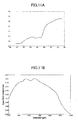
- Equalizing SNR Detector response typically is not constant over its wavelength range. Most silicon detectors are less sensitive in the blue regions than in the green region. Therefore, the blue channel of an RGB image is often more noisy than the green channel. In order to compensate for such loss of sensitivity and related increase of noise, we can design the filter module such that the signal-to-noise-ratio of the captured information is constant. For this we define ⁇ ( n ) to be the per-pixel-variance of the intensity I ( ⁇ n ) and assume it to be constant and uncorrelated for all ( s , t ) ⁇ A n , where A n is the region at the sensor plane that contains the pixels that receive the spectral response of the signal filtered by response ⁇ n .
- SNR sp n log ⁇ I ⁇ n 2 A n - 2 ⁇ ⁇ n 2 , where
- ⁇ ( n ) 2 ⁇ ⁇ ⁇ J sensor ⁇ n ⁇ s n , 0 t n , 0 2 .
- Figures 11A-11C show the spectral responses for skin y , the detector ⁇ , and the four filter cells ⁇ 1 , : : : ⁇ 4 , respectively.
- the lens parameters are the same as given in Table 3.
- the parameterization of the optimized filter partition is calculated using Eqn. (35).
- the resulting filter module is shown in Figure 12 .
- Detection Application we address the problem of how to optimize a filter partition given that the system is designed for a detection task.
- w Gaussian noise w ⁇ N (0, C) with correlation matrix C.
- the classification performance is optimized for maximum deflection coefficient.
- the signal z is the sensed spectral data integrated over the area A n that is covered by the image of partition cells with given spectral response ⁇ n in a super-pixel.
- the noise is the integrated pixel noise over the integration area A n .
- the noise obtained for a superpixel measurement has distribution N (0,C)), where C is the correlation matrix of the variables ⁇ k ⁇ An w n ( k ) and ( w n ( k )) is the multivariate Gaussian N(0, Cp).
- the scope of the invention includes other embodiments not discussed in detail above.
- other embodiments may include cost functions measuring classification performance such as the Bhattacharya distance, for example when signal and noise are modeled as Gaussian distributions.
- Alternative classification performance measurements may include structured background models which are used in band-selection for hyperspectral imaging applications.
- the cost function may measure detection performance of a single molecule in optical background in conjunction with RGB performance for the human visual system. Such an application occurs in fluorescent imaging, when an RGB image of an area and a fluorescent signal response should be captured in one imaging path.
- the filter partition layout can also be altered to enable refocusing the image along with multi-modal detection.
- the cost function for such an application could combine a metric such as a sharpness metric for testing the sharpness in each refocused image along with weighting for each imaging modality. There could also be a metric to ensure an appropriate trade-off between image resolution, number of refocus planes, and multiple imaging modalities (filter partitions). There could also be penalties for diffraction effects like crosstalk.
Landscapes
- Physics & Mathematics (AREA)
- Spectroscopy & Molecular Physics (AREA)
- General Physics & Mathematics (AREA)
- Engineering & Computer Science (AREA)
- Optics & Photonics (AREA)
- Multimedia (AREA)
- Signal Processing (AREA)
- Theoretical Computer Science (AREA)
- Evolutionary Computation (AREA)
- Geometry (AREA)
- General Engineering & Computer Science (AREA)
- Computer Hardware Design (AREA)
- Color Television Image Signal Generators (AREA)
- Optical Filters (AREA)
- Blocking Light For Cameras (AREA)
- Transforming Light Signals Into Electric Signals (AREA)
Applications Claiming Priority (1)
| Application Number | Priority Date | Filing Date | Title |
|---|---|---|---|
| US13/040,809 US8949078B2 (en) | 2011-03-04 | 2011-03-04 | Filter modules for aperture-coded, multiplexed imaging systems |
Publications (3)
| Publication Number | Publication Date |
|---|---|
| EP2495540A2 true EP2495540A2 (de) | 2012-09-05 |
| EP2495540A3 EP2495540A3 (de) | 2013-04-17 |
| EP2495540B1 EP2495540B1 (de) | 2016-10-19 |
Family
ID=45877972
Family Applications (1)
| Application Number | Title | Priority Date | Filing Date |
|---|---|---|---|
| EP12157955.1A Not-in-force EP2495540B1 (de) | 2011-03-04 | 2012-03-02 | Design von Filtermodulen für öffnungskodierte Multiplex-Bildgebungssysteme |
Country Status (3)
| Country | Link |
|---|---|
| US (2) | US8949078B2 (de) |
| EP (1) | EP2495540B1 (de) |
| JP (1) | JP6035772B2 (de) |
Cited By (3)
| Publication number | Priority date | Publication date | Assignee | Title |
|---|---|---|---|---|
| US8854525B2 (en) | 2011-04-22 | 2014-10-07 | Panasonic Corporation | Imaging device, imaging system, and imaging method |
| EP2736262A3 (de) * | 2012-11-26 | 2015-10-07 | Ricoh Company, Ltd. | Kalibrierung von plenotpischem Abbildungssystem |
| CN105547476A (zh) * | 2015-12-08 | 2016-05-04 | 中国航空工业集团公司西安航空计算技术研究所 | 一种机载多光谱视频图像采集与处理方法 |
Families Citing this family (33)
| Publication number | Priority date | Publication date | Assignee | Title |
|---|---|---|---|---|
| JP5001471B1 (ja) * | 2011-04-22 | 2012-08-15 | パナソニック株式会社 | 撮像装置、撮像システム、及び撮像方法 |
| WO2013080551A1 (ja) | 2011-11-30 | 2013-06-06 | パナソニック株式会社 | 撮像装置 |
| US9137441B2 (en) | 2012-02-16 | 2015-09-15 | Ricoh Co., Ltd. | Spatial reconstruction of plenoptic images |
| JP2014075780A (ja) * | 2012-09-14 | 2014-04-24 | Ricoh Co Ltd | 撮像装置及び撮像システム |
| WO2014050699A1 (ja) * | 2012-09-25 | 2014-04-03 | 富士フイルム株式会社 | 画像処理装置及び方法並びに撮像装置 |
| JP2014089075A (ja) * | 2012-10-29 | 2014-05-15 | Ricoh Co Ltd | 分光反射率測定システム |
| US9219866B2 (en) | 2013-01-07 | 2015-12-22 | Ricoh Co., Ltd. | Dynamic adjustment of multimode lightfield imaging system using exposure condition and filter position |
| US9565996B2 (en) | 2013-01-18 | 2017-02-14 | Ricoh Company, Ltd. | Plenoptic otoscope |
| US10327627B2 (en) | 2013-01-18 | 2019-06-25 | Ricoh Company, Ltd. | Use of plenoptic otoscope data for aiding medical diagnosis |
| CN103148936A (zh) * | 2013-01-29 | 2013-06-12 | 中国科学院光电研究院 | 一种基于液晶光阀技术的多光谱成像仪 |
| US9843740B2 (en) * | 2013-02-13 | 2017-12-12 | Panasonic Intellectual Property Management Co., Ltd. | Multispectral imaging device and multispectral imaging method |
| US9110240B2 (en) * | 2013-03-05 | 2015-08-18 | Rambus Inc. | Phase gratings with odd symmetry for high-resolution lensed and lensless optical sensing |
| US9681051B2 (en) * | 2013-08-19 | 2017-06-13 | Massachusetts Institute Of Technology | Method and apparatus for motion coded imaging |
| JP5946970B2 (ja) * | 2013-09-27 | 2016-07-06 | 富士フイルム株式会社 | 撮像装置及び撮像方法 |
| US9030580B2 (en) * | 2013-09-28 | 2015-05-12 | Ricoh Company, Ltd. | Color filter modules for plenoptic XYZ imaging systems |
| WO2015118540A1 (en) | 2014-02-06 | 2015-08-13 | Bar Ilan University | System and method for imaging with pinhole arrays |
| US9392933B2 (en) | 2014-03-06 | 2016-07-19 | Ricoh Company, Ltd. | Otoscope illumination |
| US9823338B2 (en) * | 2014-04-03 | 2017-11-21 | Evolv Technologies, Inc. | Feature extraction for radar |
| WO2015159651A1 (ja) * | 2014-04-14 | 2015-10-22 | シャープ株式会社 | 光検出装置および固体撮像装置並びにそれらの製造方法 |
| CN111812838A (zh) * | 2014-06-25 | 2020-10-23 | 技术创新动力基金(以色列)有限合伙公司 | 用于光场成像的系统和方法 |
| US9661193B2 (en) * | 2014-08-01 | 2017-05-23 | Panasonic Intellectual Property Management Co., Ltd. | Imaging apparatus and analyzing apparatus |
| US9883798B2 (en) | 2014-11-14 | 2018-02-06 | Ricoh Company, Ltd. | Simultaneous capture of filtered images of the eye |
| US10117579B2 (en) | 2014-11-14 | 2018-11-06 | Ricoh Company, Ltd. | Simultaneous capture of filtered images of the eye |
| US10284825B2 (en) | 2015-09-08 | 2019-05-07 | Rambus Inc. | Systems with integrated refractive and diffractive optics |
| US10098529B2 (en) | 2015-10-28 | 2018-10-16 | Ricoh Company, Ltd. | Optical design of a light field otoscope |
| US10228283B2 (en) * | 2016-08-12 | 2019-03-12 | Spectral Insights Private Limited | Spectral imaging system |
| US10296780B2 (en) | 2017-03-07 | 2019-05-21 | Ricoh Company, Ltd. | Automatic eardrum registration from light field data |
| US10275644B2 (en) | 2017-03-08 | 2019-04-30 | Ricoh Company, Ltd | Automatic classification of eardrum shape |
| US10616461B2 (en) * | 2017-04-25 | 2020-04-07 | Raytheon Company | Broadband optical systems and methods |
| JP7030536B2 (ja) * | 2018-01-17 | 2022-03-07 | キヤノン株式会社 | 撮像光学系および撮像装置 |
| CN108896178B (zh) * | 2018-05-29 | 2021-08-20 | 中国科学院光电研究院 | 一种多路复用多光谱成像仪 |
| CN112462455A (zh) * | 2020-11-05 | 2021-03-09 | 安徽熙泰智能科技有限公司 | 一种亚波长孔径阵列结构滤光片、显示器及其制备方法 |
| CN117571128B (zh) * | 2024-01-16 | 2024-03-29 | 长春理工大学 | 一种高分辨率偏振光谱图像成像方法及系统 |
Family Cites Families (39)
| Publication number | Priority date | Publication date | Assignee | Title |
|---|---|---|---|---|
| JP3047252B2 (ja) | 1990-11-05 | 2000-05-29 | コニカ株式会社 | 合焦制御装置 |
| US5870179A (en) | 1993-06-25 | 1999-02-09 | The Regents Of The University Of Colorado | Apparatus and method for estimating range |
| US5521695A (en) | 1993-06-25 | 1996-05-28 | The Regents Of The University Of Colorado | Range estimation apparatus and method |
| US7218448B1 (en) | 1997-03-17 | 2007-05-15 | The Regents Of The University Of Colorado | Extended depth of field optical systems |
| US6911638B2 (en) | 1995-02-03 | 2005-06-28 | The Regents Of The University Of Colorado, A Body Corporate | Wavefront coding zoom lens imaging systems |
| US20020118457A1 (en) | 2000-12-22 | 2002-08-29 | Dowski Edward Raymond | Wavefront coded imaging systems |
| US20030057353A1 (en) | 2001-07-20 | 2003-03-27 | Dowski Edward Raymond | Wavefront coding zoom lens imaging systems |
| US20020195548A1 (en) | 2001-06-06 | 2002-12-26 | Dowski Edward Raymond | Wavefront coding interference contrast imaging systems |
| JP3275010B2 (ja) | 1995-02-03 | 2002-04-15 | ザ・リジェンツ・オブ・ザ・ユニバーシティ・オブ・コロラド | 拡大された被写界深度を有する光学システム |
| US5926283A (en) | 1997-07-12 | 1999-07-20 | Optical Insights, Llc | Multi-spectral two dimensional imaging spectrometer |
| US6021005A (en) | 1998-01-09 | 2000-02-01 | University Technology Corporation | Anti-aliasing apparatus and methods for optical imaging |
| US6069738A (en) | 1998-05-27 | 2000-05-30 | University Technology Corporation | Apparatus and methods for extending depth of field in image projection systems |
| US5982497A (en) | 1998-07-09 | 1999-11-09 | Optical Insights, Llc | Multi-spectral two-dimensional imaging spectrometer |
| US6873733B2 (en) | 2001-01-19 | 2005-03-29 | The Regents Of The University Of Colorado | Combined wavefront coding and amplitude contrast imaging systems |
| US6525302B2 (en) | 2001-06-06 | 2003-02-25 | The Regents Of The University Of Colorado | Wavefront coding phase contrast imaging systems |
| US6842297B2 (en) | 2001-08-31 | 2005-01-11 | Cdm Optics, Inc. | Wavefront coding optics |
| AU2003213651A1 (en) | 2002-02-27 | 2003-09-09 | Cdm Optics, Inc. | Optimized image processing for wavefront coded imaging systems |
| US7031054B2 (en) | 2002-10-09 | 2006-04-18 | The Regent Of The University Of Colorado | Methods and systems for reducing depth of field of hybrid imaging systems |
| US7180673B2 (en) | 2003-03-28 | 2007-02-20 | Cdm Optics, Inc. | Mechanically-adjustable optical phase filters for modifying depth of field, aberration-tolerance, anti-aliasing in optical systems |
| CN1768346B (zh) | 2003-03-31 | 2010-11-17 | Cdm光学有限公司 | 用于最小化成像系统中的光程差效应的系统和方法 |
| WO2006001785A1 (en) | 2003-05-30 | 2006-01-05 | Cdm Optics, Inc. | Lithographic systems and methods with extended depth of focus |
| CN101373272B (zh) | 2003-12-01 | 2010-09-01 | 全视Cdm光学有限公司 | 用于优化光学和数字系统设计的系统和方法 |
| US7433042B1 (en) | 2003-12-05 | 2008-10-07 | Surface Optics Corporation | Spatially corrected full-cubed hyperspectral imager |
| JP4752031B2 (ja) * | 2004-10-01 | 2011-08-17 | ボード オブ トラスティーズ オブ ザ レランド スタンフォード ジュニア ユニバーシティ | 撮像の装置と方法 |
| US7256944B2 (en) * | 2005-02-18 | 2007-08-14 | Eastman Kodak Company | Compact image capture assembly using multiple lenses and image sensors to provide an extended zoom range |
| US7616841B2 (en) | 2005-06-17 | 2009-11-10 | Ricoh Co., Ltd. | End-to-end design of electro-optic imaging systems |
| WO2007008826A2 (en) | 2005-07-11 | 2007-01-18 | Infotonics Technology Center, Inc. | High speed, optically-multiplexed, hyperspectral imagers and methods thereof |
| US20070081224A1 (en) | 2005-10-07 | 2007-04-12 | Robinson M D | Joint optics and image processing adjustment of electro-optic imaging systems |
| EP1941314A4 (de) | 2005-10-07 | 2010-04-14 | Univ Leland Stanford Junior | Anordnungen und ansätze für die mikroskopie |
| US7692709B2 (en) | 2006-05-12 | 2010-04-06 | Ricoh Co., Ltd. | End-to-end design of electro-optic imaging systems with adjustable optical cutoff frequency |
| US8330087B2 (en) | 2007-10-16 | 2012-12-11 | Cambridge Research & Instrumentation, Inc. | Spectral imaging system with dynamic optical correction |
| FR2924235B1 (fr) | 2007-11-27 | 2010-08-20 | Commissariat Energie Atomique | Dispositif d'imagerie visible a filtre colore |
| KR101483714B1 (ko) * | 2008-06-18 | 2015-01-16 | 삼성전자 주식회사 | 디지털 촬상 장치 및 방법 |
| US8149400B2 (en) | 2009-04-07 | 2012-04-03 | Duke University | Coded aperture snapshot spectral imager and method therefor |
| US8248511B2 (en) | 2009-09-30 | 2012-08-21 | Ricoh Co., Ltd. | Dual-mode extended depth-of-field imaging systems |
| US8143565B2 (en) | 2009-09-30 | 2012-03-27 | Ricoh Co., Ltd. | Adjustable multimode lightfield imaging system having an actuator for changing position of a non-homogeneous filter module relative to an image-forming optical module |
| EP2642260A4 (de) * | 2010-11-16 | 2015-12-09 | Nikon Corp | Multibandkamera und multiband-bilderfassungsverfahren |
| JP5906062B2 (ja) * | 2010-12-17 | 2016-04-20 | キヤノン株式会社 | 撮像装置およびその制御方法 |
| US9250131B2 (en) | 2011-01-17 | 2016-02-02 | Ricoh Co., Ltd. | Multi-imaging system with interleaved images |
-
2011
- 2011-03-04 US US13/040,809 patent/US8949078B2/en active Active
-
2012
- 2012-02-20 JP JP2012034456A patent/JP6035772B2/ja not_active Expired - Fee Related
- 2012-03-02 EP EP12157955.1A patent/EP2495540B1/de not_active Not-in-force
-
2015
- 2015-02-02 US US14/611,844 patent/US9519737B2/en not_active Expired - Fee Related
Non-Patent Citations (1)
| Title |
|---|
| J.W. GOODMAN: "Introduction to Fourier Optics", 1986, MCGRAW-HILL |
Cited By (5)
| Publication number | Priority date | Publication date | Assignee | Title |
|---|---|---|---|---|
| US8854525B2 (en) | 2011-04-22 | 2014-10-07 | Panasonic Corporation | Imaging device, imaging system, and imaging method |
| EP2536153B1 (de) * | 2011-04-22 | 2016-04-13 | Panasonic Intellectual Property Management Co., Ltd. | Bildaufnahmevorrichtung, bildaufnahmesystem und bildaufnahmeverfahren |
| EP2736262A3 (de) * | 2012-11-26 | 2015-10-07 | Ricoh Company, Ltd. | Kalibrierung von plenotpischem Abbildungssystem |
| CN105547476A (zh) * | 2015-12-08 | 2016-05-04 | 中国航空工业集团公司西安航空计算技术研究所 | 一种机载多光谱视频图像采集与处理方法 |
| CN105547476B (zh) * | 2015-12-08 | 2018-02-09 | 中国航空工业集团公司西安航空计算技术研究所 | 一种机载多光谱视频图像采集与处理方法 |
Also Published As
| Publication number | Publication date |
|---|---|
| US8949078B2 (en) | 2015-02-03 |
| EP2495540A3 (de) | 2013-04-17 |
| JP6035772B2 (ja) | 2016-11-30 |
| EP2495540B1 (de) | 2016-10-19 |
| US20150169807A1 (en) | 2015-06-18 |
| JP2012185498A (ja) | 2012-09-27 |
| US20120226480A1 (en) | 2012-09-06 |
| US9519737B2 (en) | 2016-12-13 |
Similar Documents
| Publication | Publication Date | Title |
|---|---|---|
| EP2495540B1 (de) | Design von Filtermodulen für öffnungskodierte Multiplex-Bildgebungssysteme | |
| US7894058B2 (en) | Single-lens computed tomography imaging spectrometer and method of capturing spatial and spectral information | |
| CN103913807B (zh) | 光场成像系统、及调节全光成像系统的方法 | |
| RU2535640C2 (ru) | Формирование многоспектральных изображений | |
| US9030580B2 (en) | Color filter modules for plenoptic XYZ imaging systems | |
| US7324196B2 (en) | Spectral encoder | |
| US7283232B2 (en) | Optical spectroscopy with overlapping images | |
| US5627639A (en) | Coded aperture imaging spectrometer | |
| US5926283A (en) | Multi-spectral two dimensional imaging spectrometer | |
| CN110494723B (zh) | 波前传感器及其使用方法 | |
| US9343491B2 (en) | Spectral imaging sensors and methods | |
| US20230177655A1 (en) | System and method for digital optical aberration correction and spectral imaging | |
| EP3215818A1 (de) | Spektralbildgebungsverfahren und system | |
| Zeng et al. | Optical design of a high-resolution spectrometer with a wide field of view | |
| US7876434B2 (en) | Color camera computed tomography imaging spectrometer for improved spatial-spectral image accuracy | |
| CN112985601B (zh) | 一种基于衍射的长焦光谱编码成像系统和方法 | |
| Berkner et al. | Optimization of spectrally coded mask for multi-modal plenoptic camera | |
| CN115078266A (zh) | 光学系统及其设计方法 | |
| EP4184136A1 (de) | Abbildungsvorrichtung zur multispektralen oder hyperspektralen abbildung von mindestens einem objekt | |
| Mansur et al. | Fiber optic snapshot hyperspectral imager | |
| Llanos | Chromatic aberration correction and spectral reconstruction from colour images | |
| Gulis et al. | Low-aberration imaging monochromator with dispersion subtraction based on an axially symmetric design | |
| RU2397457C1 (ru) | Отображающий фокальный спектрометр (варианты) | |
| Berkner et al. | Design framework for a spectral mask for a plenoptic camera | |
| Hallada | The Fresnel Zone Light Field Spectral Imager |
Legal Events
| Date | Code | Title | Description |
|---|---|---|---|
| PUAI | Public reference made under article 153(3) epc to a published international application that has entered the european phase |
Free format text: ORIGINAL CODE: 0009012 |
|
| 17P | Request for examination filed |
Effective date: 20120302 |
|
| AK | Designated contracting states |
Kind code of ref document: A2 Designated state(s): AL AT BE BG CH CY CZ DE DK EE ES FI FR GB GR HR HU IE IS IT LI LT LU LV MC MK MT NL NO PL PT RO RS SE SI SK SM TR |
|
| AX | Request for extension of the european patent |
Extension state: BA ME |
|
| PUAL | Search report despatched |
Free format text: ORIGINAL CODE: 0009013 |
|
| AK | Designated contracting states |
Kind code of ref document: A3 Designated state(s): AL AT BE BG CH CY CZ DE DK EE ES FI FR GB GR HR HU IE IS IT LI LT LU LV MC MK MT NL NO PL PT RO RS SE SI SK SM TR |
|
| AX | Request for extension of the european patent |
Extension state: BA ME |
|
| RIC1 | Information provided on ipc code assigned before grant |
Ipc: G01J 1/04 20060101AFI20130308BHEP Ipc: G01J 3/28 20060101ALI20130308BHEP Ipc: G01J 3/36 20060101ALI20130308BHEP Ipc: G01J 3/02 20060101ALI20130308BHEP |
|
| GRAP | Despatch of communication of intention to grant a patent |
Free format text: ORIGINAL CODE: EPIDOSNIGR1 |
|
| INTG | Intention to grant announced |
Effective date: 20151113 |
|
| GRAP | Despatch of communication of intention to grant a patent |
Free format text: ORIGINAL CODE: EPIDOSNIGR1 |
|
| INTG | Intention to grant announced |
Effective date: 20160429 |
|
| GRAS | Grant fee paid |
Free format text: ORIGINAL CODE: EPIDOSNIGR3 |
|
| GRAA | (expected) grant |
Free format text: ORIGINAL CODE: 0009210 |
|
| AK | Designated contracting states |
Kind code of ref document: B1 Designated state(s): AL AT BE BG CH CY CZ DE DK EE ES FI FR GB GR HR HU IE IS IT LI LT LU LV MC MK MT NL NO PL PT RO RS SE SI SK SM TR |
|
| REG | Reference to a national code |
Ref country code: GB Ref legal event code: FG4D |
|
| REG | Reference to a national code |
Ref country code: CH Ref legal event code: EP |
|
| REG | Reference to a national code |
Ref country code: AT Ref legal event code: REF Ref document number: 838748 Country of ref document: AT Kind code of ref document: T Effective date: 20161115 |
|
| REG | Reference to a national code |
Ref country code: IE Ref legal event code: FG4D |
|
| REG | Reference to a national code |
Ref country code: DE Ref legal event code: R096 Ref document number: 602012024236 Country of ref document: DE |
|
| REG | Reference to a national code |
Ref country code: NL Ref legal event code: FP |
|
| REG | Reference to a national code |
Ref country code: LT Ref legal event code: MG4D |
|
| PG25 | Lapsed in a contracting state [announced via postgrant information from national office to epo] |
Ref country code: LV Free format text: LAPSE BECAUSE OF FAILURE TO SUBMIT A TRANSLATION OF THE DESCRIPTION OR TO PAY THE FEE WITHIN THE PRESCRIBED TIME-LIMIT Effective date: 20161019 |
|
| REG | Reference to a national code |
Ref country code: AT Ref legal event code: MK05 Ref document number: 838748 Country of ref document: AT Kind code of ref document: T Effective date: 20161019 |
|
| REG | Reference to a national code |
Ref country code: FR Ref legal event code: PLFP Year of fee payment: 6 |
|
| PG25 | Lapsed in a contracting state [announced via postgrant information from national office to epo] |
Ref country code: GR Free format text: LAPSE BECAUSE OF FAILURE TO SUBMIT A TRANSLATION OF THE DESCRIPTION OR TO PAY THE FEE WITHIN THE PRESCRIBED TIME-LIMIT Effective date: 20170120 Ref country code: SE Free format text: LAPSE BECAUSE OF FAILURE TO SUBMIT A TRANSLATION OF THE DESCRIPTION OR TO PAY THE FEE WITHIN THE PRESCRIBED TIME-LIMIT Effective date: 20161019 Ref country code: NO Free format text: LAPSE BECAUSE OF FAILURE TO SUBMIT A TRANSLATION OF THE DESCRIPTION OR TO PAY THE FEE WITHIN THE PRESCRIBED TIME-LIMIT Effective date: 20170119 Ref country code: LT Free format text: LAPSE BECAUSE OF FAILURE TO SUBMIT A TRANSLATION OF THE DESCRIPTION OR TO PAY THE FEE WITHIN THE PRESCRIBED TIME-LIMIT Effective date: 20161019 |
|
| PG25 | Lapsed in a contracting state [announced via postgrant information from national office to epo] |
Ref country code: FI Free format text: LAPSE BECAUSE OF FAILURE TO SUBMIT A TRANSLATION OF THE DESCRIPTION OR TO PAY THE FEE WITHIN THE PRESCRIBED TIME-LIMIT Effective date: 20161019 Ref country code: IS Free format text: LAPSE BECAUSE OF FAILURE TO SUBMIT A TRANSLATION OF THE DESCRIPTION OR TO PAY THE FEE WITHIN THE PRESCRIBED TIME-LIMIT Effective date: 20170219 Ref country code: PL Free format text: LAPSE BECAUSE OF FAILURE TO SUBMIT A TRANSLATION OF THE DESCRIPTION OR TO PAY THE FEE WITHIN THE PRESCRIBED TIME-LIMIT Effective date: 20161019 Ref country code: PT Free format text: LAPSE BECAUSE OF FAILURE TO SUBMIT A TRANSLATION OF THE DESCRIPTION OR TO PAY THE FEE WITHIN THE PRESCRIBED TIME-LIMIT Effective date: 20170220 Ref country code: ES Free format text: LAPSE BECAUSE OF FAILURE TO SUBMIT A TRANSLATION OF THE DESCRIPTION OR TO PAY THE FEE WITHIN THE PRESCRIBED TIME-LIMIT Effective date: 20161019 Ref country code: HR Free format text: LAPSE BECAUSE OF FAILURE TO SUBMIT A TRANSLATION OF THE DESCRIPTION OR TO PAY THE FEE WITHIN THE PRESCRIBED TIME-LIMIT Effective date: 20161019 Ref country code: RS Free format text: LAPSE BECAUSE OF FAILURE TO SUBMIT A TRANSLATION OF THE DESCRIPTION OR TO PAY THE FEE WITHIN THE PRESCRIBED TIME-LIMIT Effective date: 20161019 Ref country code: AT Free format text: LAPSE BECAUSE OF FAILURE TO SUBMIT A TRANSLATION OF THE DESCRIPTION OR TO PAY THE FEE WITHIN THE PRESCRIBED TIME-LIMIT Effective date: 20161019 |
|
| REG | Reference to a national code |
Ref country code: DE Ref legal event code: R097 Ref document number: 602012024236 Country of ref document: DE |
|
| PG25 | Lapsed in a contracting state [announced via postgrant information from national office to epo] |
Ref country code: DK Free format text: LAPSE BECAUSE OF FAILURE TO SUBMIT A TRANSLATION OF THE DESCRIPTION OR TO PAY THE FEE WITHIN THE PRESCRIBED TIME-LIMIT Effective date: 20161019 Ref country code: CZ Free format text: LAPSE BECAUSE OF FAILURE TO SUBMIT A TRANSLATION OF THE DESCRIPTION OR TO PAY THE FEE WITHIN THE PRESCRIBED TIME-LIMIT Effective date: 20161019 Ref country code: EE Free format text: LAPSE BECAUSE OF FAILURE TO SUBMIT A TRANSLATION OF THE DESCRIPTION OR TO PAY THE FEE WITHIN THE PRESCRIBED TIME-LIMIT Effective date: 20161019 Ref country code: SK Free format text: LAPSE BECAUSE OF FAILURE TO SUBMIT A TRANSLATION OF THE DESCRIPTION OR TO PAY THE FEE WITHIN THE PRESCRIBED TIME-LIMIT Effective date: 20161019 Ref country code: RO Free format text: LAPSE BECAUSE OF FAILURE TO SUBMIT A TRANSLATION OF THE DESCRIPTION OR TO PAY THE FEE WITHIN THE PRESCRIBED TIME-LIMIT Effective date: 20161019 |
|
| PLBE | No opposition filed within time limit |
Free format text: ORIGINAL CODE: 0009261 |
|
| STAA | Information on the status of an ep patent application or granted ep patent |
Free format text: STATUS: NO OPPOSITION FILED WITHIN TIME LIMIT |
|
| PG25 | Lapsed in a contracting state [announced via postgrant information from national office to epo] |
Ref country code: IT Free format text: LAPSE BECAUSE OF FAILURE TO SUBMIT A TRANSLATION OF THE DESCRIPTION OR TO PAY THE FEE WITHIN THE PRESCRIBED TIME-LIMIT Effective date: 20161019 Ref country code: SM Free format text: LAPSE BECAUSE OF FAILURE TO SUBMIT A TRANSLATION OF THE DESCRIPTION OR TO PAY THE FEE WITHIN THE PRESCRIBED TIME-LIMIT Effective date: 20161019 Ref country code: BG Free format text: LAPSE BECAUSE OF FAILURE TO SUBMIT A TRANSLATION OF THE DESCRIPTION OR TO PAY THE FEE WITHIN THE PRESCRIBED TIME-LIMIT Effective date: 20170119 |
|
| 26N | No opposition filed |
Effective date: 20170720 |
|
| REG | Reference to a national code |
Ref country code: CH Ref legal event code: PL |
|
| PG25 | Lapsed in a contracting state [announced via postgrant information from national office to epo] |
Ref country code: SI Free format text: LAPSE BECAUSE OF FAILURE TO SUBMIT A TRANSLATION OF THE DESCRIPTION OR TO PAY THE FEE WITHIN THE PRESCRIBED TIME-LIMIT Effective date: 20161019 Ref country code: MC Free format text: LAPSE BECAUSE OF FAILURE TO SUBMIT A TRANSLATION OF THE DESCRIPTION OR TO PAY THE FEE WITHIN THE PRESCRIBED TIME-LIMIT Effective date: 20161019 |
|
| REG | Reference to a national code |
Ref country code: IE Ref legal event code: MM4A |
|
| PG25 | Lapsed in a contracting state [announced via postgrant information from national office to epo] |
Ref country code: LU Free format text: LAPSE BECAUSE OF NON-PAYMENT OF DUE FEES Effective date: 20170302 |
|
| PG25 | Lapsed in a contracting state [announced via postgrant information from national office to epo] |
Ref country code: IE Free format text: LAPSE BECAUSE OF NON-PAYMENT OF DUE FEES Effective date: 20170302 Ref country code: CH Free format text: LAPSE BECAUSE OF NON-PAYMENT OF DUE FEES Effective date: 20170331 Ref country code: LI Free format text: LAPSE BECAUSE OF NON-PAYMENT OF DUE FEES Effective date: 20170331 |
|
| REG | Reference to a national code |
Ref country code: FR Ref legal event code: PLFP Year of fee payment: 7 |
|
| PG25 | Lapsed in a contracting state [announced via postgrant information from national office to epo] |
Ref country code: MT Free format text: LAPSE BECAUSE OF NON-PAYMENT OF DUE FEES Effective date: 20170302 |
|
| PGFP | Annual fee paid to national office [announced via postgrant information from national office to epo] |
Ref country code: GB Payment date: 20190320 Year of fee payment: 8 Ref country code: DE Payment date: 20190321 Year of fee payment: 8 Ref country code: FR Payment date: 20190322 Year of fee payment: 8 |
|
| PGFP | Annual fee paid to national office [announced via postgrant information from national office to epo] |
Ref country code: BE Payment date: 20190320 Year of fee payment: 8 Ref country code: NL Payment date: 20190320 Year of fee payment: 8 |
|
| PG25 | Lapsed in a contracting state [announced via postgrant information from national office to epo] |
Ref country code: HU Free format text: LAPSE BECAUSE OF FAILURE TO SUBMIT A TRANSLATION OF THE DESCRIPTION OR TO PAY THE FEE WITHIN THE PRESCRIBED TIME-LIMIT; INVALID AB INITIO Effective date: 20120302 |
|
| PG25 | Lapsed in a contracting state [announced via postgrant information from national office to epo] |
Ref country code: CY Free format text: LAPSE BECAUSE OF NON-PAYMENT OF DUE FEES Effective date: 20161019 |
|
| PG25 | Lapsed in a contracting state [announced via postgrant information from national office to epo] |
Ref country code: MK Free format text: LAPSE BECAUSE OF FAILURE TO SUBMIT A TRANSLATION OF THE DESCRIPTION OR TO PAY THE FEE WITHIN THE PRESCRIBED TIME-LIMIT Effective date: 20161019 |
|
| PG25 | Lapsed in a contracting state [announced via postgrant information from national office to epo] |
Ref country code: TR Free format text: LAPSE BECAUSE OF FAILURE TO SUBMIT A TRANSLATION OF THE DESCRIPTION OR TO PAY THE FEE WITHIN THE PRESCRIBED TIME-LIMIT Effective date: 20161019 |
|
| PG25 | Lapsed in a contracting state [announced via postgrant information from national office to epo] |
Ref country code: AL Free format text: LAPSE BECAUSE OF FAILURE TO SUBMIT A TRANSLATION OF THE DESCRIPTION OR TO PAY THE FEE WITHIN THE PRESCRIBED TIME-LIMIT Effective date: 20161019 |
|
| REG | Reference to a national code |
Ref country code: DE Ref legal event code: R119 Ref document number: 602012024236 Country of ref document: DE |
|
| REG | Reference to a national code |
Ref country code: NL Ref legal event code: MM Effective date: 20200401 |
|
| REG | Reference to a national code |
Ref country code: BE Ref legal event code: MM Effective date: 20200331 |
|
| PG25 | Lapsed in a contracting state [announced via postgrant information from national office to epo] |
Ref country code: NL Free format text: LAPSE BECAUSE OF NON-PAYMENT OF DUE FEES Effective date: 20200401 |
|
| PG25 | Lapsed in a contracting state [announced via postgrant information from national office to epo] |
Ref country code: DE Free format text: LAPSE BECAUSE OF NON-PAYMENT OF DUE FEES Effective date: 20201001 Ref country code: FR Free format text: LAPSE BECAUSE OF NON-PAYMENT OF DUE FEES Effective date: 20200331 |
|
| PG25 | Lapsed in a contracting state [announced via postgrant information from national office to epo] |
Ref country code: BE Free format text: LAPSE BECAUSE OF NON-PAYMENT OF DUE FEES Effective date: 20200331 |
|
| GBPC | Gb: european patent ceased through non-payment of renewal fee |
Effective date: 20200302 |
|
| PG25 | Lapsed in a contracting state [announced via postgrant information from national office to epo] |
Ref country code: GB Free format text: LAPSE BECAUSE OF NON-PAYMENT OF DUE FEES Effective date: 20200302 |