EP2495381B1 - System und Verfahren zum Verriegeln und Entriegeln einer Tür eines Toilettenmoduls eines öffentlichen Verkehrsmittels - Google Patents
System und Verfahren zum Verriegeln und Entriegeln einer Tür eines Toilettenmoduls eines öffentlichen Verkehrsmittels Download PDFInfo
- Publication number
- EP2495381B1 EP2495381B1 EP11382056.7A EP11382056A EP2495381B1 EP 2495381 B1 EP2495381 B1 EP 2495381B1 EP 11382056 A EP11382056 A EP 11382056A EP 2495381 B1 EP2495381 B1 EP 2495381B1
- Authority
- EP
- European Patent Office
- Prior art keywords
- door
- locking
- module
- unlocking
- signal
- Prior art date
- Legal status (The legal status is an assumption and is not a legal conclusion. Google has not performed a legal analysis and makes no representation as to the accuracy of the status listed.)
- Not-in-force
Links
- 238000000034 method Methods 0.000 title claims description 11
- 238000001514 detection method Methods 0.000 claims description 37
- 230000007246 mechanism Effects 0.000 claims description 22
- 230000008569 process Effects 0.000 claims description 10
- 239000012530 fluid Substances 0.000 claims description 6
- 238000004590 computer program Methods 0.000 claims description 2
- 238000010586 diagram Methods 0.000 description 10
- XLYOFNOQVPJJNP-UHFFFAOYSA-N water Substances O XLYOFNOQVPJJNP-UHFFFAOYSA-N 0.000 description 10
- 230000008901 benefit Effects 0.000 description 7
- 230000007257 malfunction Effects 0.000 description 7
- 239000002351 wastewater Substances 0.000 description 4
- 238000012423 maintenance Methods 0.000 description 3
- 238000004140 cleaning Methods 0.000 description 2
- 208000003443 Unconsciousness Diseases 0.000 description 1
- 230000002426 anti-panic effect Effects 0.000 description 1
- 230000015556 catabolic process Effects 0.000 description 1
- 238000001035 drying Methods 0.000 description 1
- 238000011010 flushing procedure Methods 0.000 description 1
- 238000012986 modification Methods 0.000 description 1
- 230000004048 modification Effects 0.000 description 1
- 238000005406 washing Methods 0.000 description 1
Images


Classifications
-
- E—FIXED CONSTRUCTIONS
- E05—LOCKS; KEYS; WINDOW OR DOOR FITTINGS; SAFES
- E05B—LOCKS; ACCESSORIES THEREFOR; HANDCUFFS
- E05B65/00—Locks or fastenings for special use
- E05B65/0035—Locks or fastenings for special use for privacy rooms, e.g. bathrooms
-
- B—PERFORMING OPERATIONS; TRANSPORTING
- B61—RAILWAYS
- B61D—BODY DETAILS OR KINDS OF RAILWAY VEHICLES
- B61D19/00—Door arrangements specially adapted for rail vehicles
- B61D19/02—Door arrangements specially adapted for rail vehicles for carriages
-
- B—PERFORMING OPERATIONS; TRANSPORTING
- B61—RAILWAYS
- B61D—BODY DETAILS OR KINDS OF RAILWAY VEHICLES
- B61D35/00—Sanitation
-
- E—FIXED CONSTRUCTIONS
- E05—LOCKS; KEYS; WINDOW OR DOOR FITTINGS; SAFES
- E05B—LOCKS; ACCESSORIES THEREFOR; HANDCUFFS
- E05B51/00—Operating or controlling locks or other fastening devices by other non-mechanical means
- E05B51/02—Operating or controlling locks or other fastening devices by other non-mechanical means by pneumatic or hydraulic means
-
- E—FIXED CONSTRUCTIONS
- E05—LOCKS; KEYS; WINDOW OR DOOR FITTINGS; SAFES
- E05B—LOCKS; ACCESSORIES THEREFOR; HANDCUFFS
- E05B63/00—Locks or fastenings with special structural characteristics
- E05B63/0065—Operating modes; Transformable to different operating modes
- E05B63/0069—Override systems, e.g. allowing opening from inside without the key, even when locked from outside
Definitions
- the present invention relates to a system for locking and unlocking the door of a toilet module in a transportation vehicle, a process for locking and unlocking said door using said system and a computer program product to carry out said process.
- Toilet modules for public transportation vehicles are known, such as those in trains, which include a clean water tank, a wastewater tank and flushing systems to discharge the wastewater from the toilet bowl to the wastewater tank.
- US 2009/0007328 discloses a self-cleaning public toilet comprising a safety and alarm system.
- the safety and alarm system includes a plurality of load cells that weigh the user who has entered a space; a photoelectric-sensor device for detecting the presence or otherwise of a person in the space during washing and drying of the inside of the toilet; and at least one pressure switch located in a pneumatic cylinder that actuates a rotating arm for cleaning a toilet bowl.
- the cited modules have a locking and unlocking system for the door which includes a locking and unlocking mechanism which is activated by a pneumatic actuator linked to an electronic control unit which detects the locked or unlocked position of a lever located inside the module.
- the same electronic control unit is configured to detect any malfunctioning of the module, be it because the water level in the waste water tank has reached its limit, due to lack of air or power supply or, for example, due to the lack of clean water in the tank.
- the aforementioned electronic control unit of the module sends an unlocking signal to the pneumatic actuator which activates the unlocking mechanism of the door. Therefore, in the event of a breakdown due to malfunctioning, the user can always leave the module.
- the existing locking and unlocking systems include a second locking and unlocking mechanism for the door which is activated from outside the module.
- This mechanism is associated with a square head key which only the train staff can operate.
- the same staff activates the second locking mechanism using the square head key so that the door remains permanently locked.
- the objective of the present invention is to solve the aforementioned problems, developing a system for locking and unlocking the door of a toilet module in a public transportation vehicle which has the advantages that will be described below
- the present invention provides a locking and unlocking system for the door of a toilet module in a public transportation vehicle, as claimed in claim 1.
- the system of the present invention has the advantage that it is possible to lock the door from the exterior by the train staff, and at the same time, unlock said door by a user that may have been left inside. In this way, it is guaranteed that the module remains out of order and locked without the danger of a user being left inside, it being possible to lock the door again when the user leaves when the signal to lock from the exterior persists.
- the means of locking and unlocking the door are associated with said means of processing and control in that they can receive a signal to lock or unlock the door be it from the exterior (second means of detection) or from the interior (first means of detection).
- Another advantage of the system stems from the fact that it is possible to carry out an automatic out of order of all of the modules in the vehicle once a journey has been completed, for example, to carry out maintenance operations, given that the means of locking and unlocking the door can be controlled automatically from the exterior without the risk of anybody being left locked inside.
- said system comprises means of detection of a failure of the module, and wherein said means of processing and control are configured to allow said door to be locked at any time when said means of processing and control receive a failure signal coming from said means of detection, it being possible said door to be unlocked by said means of unlocking upon receiving from said means of processing and control an unlocking signal coming from said first means of detection from the interior of the module, allowing said means of processing and control to lock said door again in order to leave the module out of order when the failure signal persists.
- the system has the advantage of when an out of order signal is produced due to a failure of the module, for example, owing to a lack of water in the clean water tank, the door locks to leave the module out of order, it being possible to unlock it at any moment from the interior (first means of detection) to allow a user to exit.
- the module remains locked and out of order, and as a result preventing incorrect use. Furthermore, if there is a user inside, said user can exit and the door will lock again, providing the failure signal continues.
- the means of locking and unlocking the door are associated with said means of processing and control in that they can receive a signal to lock or unlock the door coming from the interior (first means of detection) and/or from said means that detect the malfunction.
- said means of locking and unlocking includes a door locking mechanism actuated by a fluid dynamic actuator, and a closed-door electronic sensor associated with said actuator.
- said locking and unlocking mechanism includes a locking piston actuated by said actuator and a stop element positioned over the door to prevent said door from opening when said stop element comes into contact with said piston.
- said system is applied on a door that is a sliding door.
- a door that is a sliding door.
- any other type of door could be used.
- said first means of detection of the order to lock or unlock the door coming from the interior of the module include a lever for locking and unlocking situated in the interior of the module, a fluid dynamic actuator to actuate said lever, and at least one electronic sensor associated with said actuator to detect the position of said lever and supply a signal to said means of processing and control.
- said second means of detection of an order to lock or unlock the door coming from the exterior of said module include a lock provided with a locking and unlocking key, and at least one electronic sensor associated with said key to detect the position of said key and supply a signal to said means of processing and control.
- said system comprises an indicator of the status of the module, said indicator being associated with said means of processing and control to supply an informative signal on the status of the module according to a signal emitted by said first or second means of detection of the order to lock or unlock the door, or according to a signal emitted by said means of detection of a failure of the module.
- said indicator of the status of the module includes at least one fluid dynamic actuator associated with said informative signal in order to show said informative signal according to the signal emitted by said means of detection of the order to lock or unlock the door or according to said means of detection of a failure of the module.
- said indicator of the status of the module includes at least three pictograms to provide tactile information of at least three states of the module (for example, out of order, occupied and free).
- said door is an automatic door and said system comprises a push button to open and close said door automatically from the interior or exterior of the module, said button being associated with said means of processing and control to supply a signal to unlock said door automatically to said means of locking and unlocking said door, such that said door can be at the same time unlocked and open.
- This embodiment is useful for people with disabilities and has an anti-panic function.
- said means of detection of a failure include means of detection of a lack of electric energy for the proper operation of the module and, again preferably, said means of processing and control include, in addition, an automaton of pneumatic logical functions.
- the automaton of pneumatic logical functions has the advantage of guaranteeing efficient and reliable operation of the system for locking and unlocking in absence of power supply.
- said automaton is configured to allow the door to be unlocked at any time upon receiving an unlocking signal coming from the pneumatic sensor associated with the key of said second means. In this way, the door can be unlocked at any moment from the exterior in the absence of power supply.
- the present invention provides a process for locking and unlocking the door of a toilet module in a public transportation vehicle, by using the claimed system which comprises the stages of;
- This process has the advantage that it envisages the locking of the door from the exterior by the train staff, and at the same time, the unlocking of said door by a user that may have been left inside. In this way it is guaranteed that the module remains out of order and locked without the danger of a user being left inside, it being possible the door to be locked again when the user leaves if the locking signal coming from the exterior continues.
- said process comprises the stages of;
- the following discloses a preferred embodiment of the locking and unlocking system of a door 1 of a module 2 of the toilet in a public transportation vehicle, such as for example, a train.
- This embodiment includes means of processing and control that are configured by an electric processing and control unit and a pneumatic processing and control unit, also called herein automaton of pneumatic logical functions.
- either one or other unit is determined by the operating conditions of the module 2. Such that, whenever the module 2 has power supply, the system will be governed by the electronic processing and control unit, while the system will be governed by the pneumatic automaton, only in the event that there is no power supply.
- both electric sensors and pneumatic sensors have been envisaged to detect the actions which operate in the system.
- the toilet module 2 includes a sliding door 1 with an upper guide 3 that has means of locking and unlocking the door 1.
- the means of locking and unlocking include a locking mechanism 4 which consists in a locking piston 5 associated with a stop element 6 positioned above the sliding door 1.
- the mechanism 4 is actuated by a pneumatic actuator 7 which is associated with a closed door pneumatic sensor 8 and a closed door electric sensor 9, operating either one or other sensor according to whether the control of the system is governed by the electric automaton or the pneumatic automaton.
- the locking of the door 1 is produced, when the door is closed, in the event that the pneumatic actuator 7 receives a locking signal coming from the means of processing and control of the system which makes the piston 5 to descend.
- the unlocking is produced when the same actuator 7 receives an unlocking signal from the same means of processing and control.
- the signals for locking and unlocking the door 1 are emitted by electric sensors 10, 11 or by pneumatic sensors 12, according to whether the system is governed by the electric automaton or the pneumatic automaton. In either case, these sensors 10, 11, 12 are associated with a locking and unlocking lever 13 which is actuated by the user or the system itself (in the event of a failure being detected), by way of a pneumatic actuator 14.
- the locking of the door 1 from the interior is produced, with the door closed, when the user or the system itself moves the lever 13 by way of the actuator 14 until the position in which there is one of the said electric sensors 10 which sends the locking signal to the means of processing and control.
- the user or the system itself To unlock the door 1 from the interior, the user or the system itself must move the lever 13 to a position in which there is another electric sensor 11 which sends an unlocking signal to the means of processing and control.
- a pneumatic sensor 12 is envisaged in order to be able to also unlock the door in the event of a failure in the power supply by way of the automaton of pneumatic logical functions.
- the locking and unlocking lever 13, the electric sensors 10, 11, the pneumatic sensors 12 and the pneumatic actuator 14 form the first means which detect the order to lock or unlock the door 1 from the interior of the module. These means are positioned in a plate 15 situated in the interior of the module 2.
- Figure 3 shows a front view of said plate 15 in which can be appreciated, in addition to the lever 13, the indicator 16 of the status of the module in which tactile pictograms are displayed which provide the user with information on the status of the module (out of order, occupied and free) according to the signal they receive from the means of processing and control.
- FIG. 4 shows the front view of the same plate 15 in which represented schematically are, the pneumatic actuator 14 of the lever 13, electric sensors 10, 11 and the pneumatic sensor 12 associated with said lever 13 and a couple of pneumatic actuators 17, 18 associated with the pictograms.
- Said pictograms provide information on the status of the module 2 according to the signal proceeding from the means of processing and control.
- one of the novel features of the system of the present invention stems from the fact that the door 1 can be locked from the exterior by the train staff, it being possible at the same time to unlock it from the interior in order to allow a user locked inside to exit.
- the locking of the door 1 from the exterior is produced, with the door 1 being closed, when a shaft 23 of the lock 19 moves a key 24 to the position in which there is the first electric sensor 21 which sends the locking signal to the means of processing and control, which in turn, send the signal to the pneumatic actuator 7 of the locking mechanism 4 of the door 1.
- shaft 23 of the lock 19 To unlock the door 1 from the exterior, shaft 23 of the lock 19 must move the key 24 to the position in which there is the second electric sensor 22 which supplies the unlocking signal to the means of processing and control.
- a pneumatic sensor 20 is envisaged in order to be able to also unlock the door 1 in the event of a failure in the power supply by way of the automaton of pneumatic logical functions.
- the lock 19, the shaft 23, the key 24, the electric sensors 21, 22 and the pneumatic sensor 20 form the second means which detect the order to open or close the door 1 from the exterior. These means are positioned in a plate 25 situated in the exterior of the module 2.
- Figure 5 shows a front view of said plate 25, in which can be appreciated, in addition to the lock 19, the indicator 26 of the status of the module in which tactile pictograms are displayed which provide the user with information on the status of the module (out of order, occupied and free).
- the lock 19 includes, in addition to the positions of toilet locked (WC locked) and toilet unlocked (WC unlocked), the position of toilet in service (WC in service).
- the key 24 of the lock 19 is found in an intermediate position in which no signal is sent to the means of processing and control, the system being able to operate in a normal way.
- FIG. 6 shows the rear view of the same plate 25 in which represented schematically are, the shaft 23, the key 24, the electric sensors 21, 22 and the pneumatic sensor 20 associated with said key 24 and a couple of pneumatic actuators 27, 28 associated with the pictograms.
- Said pictograms provide information on the status of the module 2 according to the signal which they receive from the means of processing and control of the system.
- the door can be an automatic door envisaged with a push button 29 to open or close said door automatically from the interior or exterior of the module 2. This door is useful for users with disabilities.
- FIGs 7 and 8 represent the front views of an interior plate 30 and an exterior plate 31 of the module 2 envisaged with an automatic door.
- the plates 30, 31 are identical to the plates in figures 3 and 4 with the only particularity that they additionally include a button 29.
- the button 29 is associated with the means of processing and control of the system in order to be able to send an unlocking signal to the mechanism 4 of the door. In this way, it is possible to open and unlock the door with a single push of a button facilitating the exit of the user in the case of panic.
- the system has the advantage of when detecting an out of order signal that has been produced due to a failure of the module 2, for example, owing to a lack of water in the clean water tank or due to a lack of power supply, the door 1 locks to leave the module 2 out of order, it being possible to unlock the module at any moment from the interior or exterior to allow a user to exit.
- the system has means of detection of a failure (for example, a sensor for the water level in the tanks, power supply sensor, etc%) which are associated with the processing and electronic control unit to be able to supply a locking signal at any moment to the pneumatic actuator 7 of the locking means.
- a failure for example, a sensor for the water level in the tanks, power supply sensor, etc.
- the processing and electronic control unit sends, simultaneously, a signal to the actuator 14 of the lever 13 in order to put it in a locked position, and the actuators 17, 18 of the tactile indicator to show the out of order signal.
- an automaton of pneumatic logical functions will enter into operation which will respond to the signals sent by the pneumatic sensors of the system.
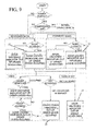
- the diagram in figure 9 represents the operating algorithm of the system when limited without air and/or power supply (degrade mode). In this way the system is governed by the electronic processing and control unit (if there is power supply) or the pneumatic processing and control unit (if there is no power supply), it being necessary to have a tank of reserve air to make the system operate if there is a shortage of it.
- the first situation is that in which a user inside wants to exit, the user proceeds to move the lever 13 into the unlocked position (free) in which there are the electric sensor 11 and pneumatic sensor 12 which supply an unlocking signal to the (electronic or pneumatic) processing and control unit so that pneumatic actuator 7 of the locking and unlocking mechanism 4 is actuated.
- the user can exit the module 2 by opening the door 1 manually or, in the event that the door is automatic, by pressing the button 29.
- a second situation is that in which the train staff detect the out of order and wish to open the door 1 to carry out, for example, a maintenance operation, the train staff proceed to move the key 24 of the lock 19 to the position (WC unlocked) in which there are the electric sensor 22 and pneumatic sensor 20 which supply an unlocking signal to the (electronic or pneumatic) processing and control unit so that the pneumatic actuator 5 of the locking and unlocking mechanism 4 is actuated.
- the train staff can open the door 1 and access the module 2.
- the (electronic or pneumatic) processing and control unit sends, simultaneously, a signal to the actuator 14 of the lever 13 in order to put it in an unlocked position (free), while the out of order signal is maintained on the indicator (16, 26).
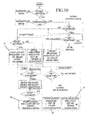
- the diagram in figure 10 represents the operating algorithm of the system in security mode and in normal operation mode. In these operation modes the system is always governed by the electronic processing and control unit.
- the first situation is that in which a user inside wants to exit, the user proceeds to move the lever 13 into the unlocked position (free) in which there is the electric sensor 11 which sends an unlocking signal to the electronic processing and control unit so that the pneumatic actuator 7 of the locking and unlocking mechanism 4 is actuated.
- the user can exit the module 2 by opening the door 1 manually or, in the event that the door is automatic, by pressing the button 29.
- a second situation is that in which the train staff detect the out of order and wish to open the door 1 to carry out, for example, a maintenance operation, the train staff proceed to move the key 24 of the lock 19 to the position (WC unlocked) in which there is the electric sensor 22 which sends an unlocking signal to the electronic processing and control unit so that the pneumatic actuator 7 of the locking and unlocking mechanism 4 is actuated. In this way, the train staff can open the door 1 and access the module 2.
- the electronic processing and control unit sends, simultaneously, a signal to the actuator 14 of the lever 13 in order to put it in an unlocked position (free).
- Diagram 10 also shows the normal operation mode of the system when the electronic processing and control unit does not detect any failure. In this event, two situations can exist.
- the train staff position the key 24 of the lock 19 to the toilet unlocked position (WC unlocked) because, for example, they detect that the toilet has been occupied for a long time and wish to know if there is an unconscious person inside.
- the electric sensor 22 which sends an unlocking signal to the electronic processing and control unit so that the pneumatic actuator 7 of the locking and unlocking mechanism 4 is actuated.
- the train staff can open the door 1 and access the module 2 to see what has happened.
- the electronic processing and control unit sends, simultaneously, a signal to the actuator 14 of the lever 13 in order to put it in an unlocked position (free).
- the toilet remains permanently unlocked.
- the train staff position the key 24 of the lock 19 to the toilet locked position (WC locked) because they wish, for example, to leave the toilet out of order.
- the electric sensor 21 which supply a locking signal to the electronic processing and control unit so that it proceeds to lock the module 2 as if there were a failure.
- the train staff positions the key 24 of the lock 19 to the toilet in service position (WC in service). In this position the system operates normally awaiting the locking or unlocking signal of the lever 13 which would have to be actuated now by the user when accessing the module 2.
- the system of the present invention locks the door faced with any out of order produced by the train staff themselves, due to a lack of power and/or air supply, or any other failure detection, allowing at any moment a user or the train staff themselves the possibility to unlock the door in order to exit the module or access the module 2.
Landscapes
- Engineering & Computer Science (AREA)
- Mechanical Engineering (AREA)
- Structural Engineering (AREA)
- Health & Medical Sciences (AREA)
- Epidemiology (AREA)
- General Health & Medical Sciences (AREA)
- Public Health (AREA)
- Lock And Its Accessories (AREA)
Claims (15)
- Verriegelungs- und Entriegelungssystem für die Tür (1) eines Toilettenmoduls (2) in einem öffentlichen Transportmittel, das Verriegelungs- und Entriegelungsmittel (3, 4, 5, 6, 7, 8, 9) für die Tür (1), wenn die Tür (1) geschlossen ist, erste Mittel zum Detektieren (11, 12, 13,14) eines Befehls zum Verriegeln oder Entriegeln der Tür, der aus dem Inneren des Moduls (2) kommt, und Verarbeitungs- und Steuermittel aufweist, um ein Signal an die Verriegelungs- und Entriegelungsmittel (3, 4, 5, 6, 7, 8, 9) zu übermitteln, das von einem von den ersten Mitteln zum Detektieren (11, 12, 13,14) abgegebenen Signal abhängt, wobei das Verriegelungs- und Entriegelungssystem zweite Mittel zum Detektieren (19, 20, 21, 22, 23, 24) eines Befehls zum Verriegeln oder Entriegeln der Tür (1) umfasst, der von außerhalb des Moduls (2) kommt, wobei die zweiten Mittel zum Detektieren (19, 20, 21, 22, 23, 24) mit den Verarbeitungs- und Steuermitteln verbunden sind, um den Verriegelungsmitteln (3, 4, 5, 6, 7, 8, 9) ein Türverriegelungssignal zu übermitteln, um das Modul (2) außer Betrieb zu belassen, wobei die Verarbeitungs- und Steuermittel derart ausgestaltet sind, um- das Entriegeln der Tür (1) zu erlauben, damit der Benutzer zu jeder Zeit aus dem Inneren des Moduls (2) austreten kann, wenn die Verarbeitungs- und Steuermittel ein Entriegelungssignal von den ersten Mitteln zum Detektieren (11, 12, 13, 14) empfangen, und- das Verriegeln der Tür (1) zu ermöglichen, um das Modul (2) erneut außer Betrieb zu belassen, sobald die Tür (1) erneut durch den Benutzer geschlossen ist und das Verriegelungssignal andauert.
- Verriegelungs- und Entriegelungssystem nach Anspruch 1, das Mittel zum Detektieren eines Fehlers des Moduls aufweist, und wobei die Verarbeitungs- und Steuermittel derart ausgebildet sind, dass sie der Tür (1) ermöglichen, zu jeder Zeit verriegelt zu werden, wenn die Verarbeitungs- und Steuermittel ein Fehlersignal empfangen, das von den Mittel zum Detektieren kommt, wobei es möglich ist, dass die Tür (1) von den Entriegelungsmitteln (3, 4, 5, 6, 7, 8, 9) nach Empfangen eines Entriegelungssignals von den Verarbeitungs- und Steuermitteln, das von den ersten Mittel zum Detektieren (11, 12, 13, 14) aus dem Inneren des Moduls (2) kommt, entriegelt wird, was es den die Verarbeitungs- und Steuermitteln ermöglicht, die Tür (1) erneut zu verriegeln, um das Modul (2) außer Betrieb zu belassen, wenn das Fehlersignal andauert.
- Verriegelungs- und Entriegelungssystem nach einem der vorhergehenden Ansprüche, bei dem die Verriegelungs- und Entriegelungsmittel einen Türverriegelungsmechanismus (4), der durch einen fluiddynamischen Aktuator (7) aktiviert wird, und einen den Schließzustand der Tür feststellenden elektrischen Sensor (9) umfassen, der mit dem Aktuator (7) verbunden ist.
- Verriegelungs- und Entriegelungssystem nach Anspruch 3, bei dem der Verriegelungs- und Entriegelungsmechanismus (4) einen Verriegelungsstift (5), der durch den Aktuator (7) aktiviert wird, und ein Stoppelement (6) umfasst, das über der Tür (1) angeordnet ist, um die Tür (1) am Öffnen zu hindern, wenn das Stoppelement (6) in Kontakt mit dem Stift (5) kommt.
- Verriegelungs- und Entriegelungssystem nach einem der vorhergehenden Ansprüche, bei dem die ersten Mittel zum Detektieren des Befehls, die Tür aus dem Inneren des Moduls zu verriegeln oder zu entriegeln, einen Hebel zum Verriegeln und Entriegeln (13), der in dem Inneren des Moduls angeordnet ist, einen fluiddynamischen Aktuator (14) zum Aktivieren des Hebels (13), und mindestens einen elektronischen Sensor (11, 10) umfassen, der mit dem Aktuator (14) verbunden ist, um die Position des Hebels (13) zu detektieren und ein Signal an die Verarbeitungs- und Steuermittel zu übermitteln.
- Verriegelungs- und Entriegelungssystem nach einem der vorhergehenden Ansprüche, bei dem die zweiten Mittel zum Detektieren, des Befehls, die Tür des Moduls von außen zu verriegeln oder zu entriegeln, ein Schloss (19), das mit einem Verriegelungs- und Entriegelungsschlüssel (24) versehen ist, und mindestens einen elektronischen Sensor (21, 22) umfassen, der mit dem Schlüssel (24) verbunden ist, um die Position des Schlüssels (24) zu detektieren und ein Signal an die Verarbeitungs- und Steuermittel zu übermitteln.
- Verriegelungs- und Entriegelungssystem nach einem der vorhergehenden Ansprüche, das einen Indikator (16, 26) für den Status des Moduls umfasst, wobei der Indikator mit den Verarbeitungs- und Steuermitteln verbunden ist, um ein Informations-Signal über den Status des Moduls gemäß einem Signal zu übertragen, das von den ersten (11, 12, 13, 14) oder zweiten (19, 20, 21, 22, 23, 24) Mitteln zum Detektieren des Befehls, die Tür (1) zu verriegeln oder zu entriegeln, ausgegeben wird, oder gemäß einem Signal, das durch die Mittel zum Detektieren eines Fehlers des Moduls ausgegeben wird.
- Verriegelungs- und Entriegelungssystem nach Anspruch 7, bei dem der Indikator (16, 26) über den Status des Moduls mindestens einen fluiddynamischen Aktuator (17, 18, 27, 28) umfasst, der mit dem Informations-Signal verbunden ist, um das Informations-Signal gemäß dem Signal anzuzeigen, das von den ersten (11, 12, 13, 14) und den zweiten (19, 20, 21, 22, 23, 24) Mitteln zum Detektieren des Befehls, die Tür zu verriegeln oder zu entriegeln, ausgegeben wird, oder gemäß den Mitteln zum Detektieren eines Fehlers des Moduls anzuzeigen.
- Verriegelungs- und Entriegelungssystem nach einem der vorhergehenden Ansprüche, bei dem die Tür eine automatische Tür (1) ist und das System einen Druckknopf (29) zum automatischen Öffnen und Schließen der Tür aus dem Inneren oder von außerhalb des Moduls (2) aufweist, wobei der Druckknopf (29) mit den Verarbeitungs- und Steuermitteln verbunden ist, um ein Signal zum Entriegeln der automatischen Tür (1) an die Verriegelungs- und Entriegelungsmittel (3, 4, 5, 6, 7, 8, 9) der Tür derart zu übermitteln, dass die Tür (1) zur selben Zeit durch den Druckknopf (29) entriegelt und geöffnet werden kann.
- Verriegelungs- und Entriegelungssystem nach einem der Ansprüche 2 bis 9, bei dem die Mittel zum Detektieren eines Fehlers Mittel zum Detektieren eines Mangels an elektrischer Energie für den ordnungsgemäßen Betrieb des Moduls (2) aufweisen.
- Verriegelungs- und Entriegelungssystem nach Anspruch 10, bei dem die Verarbeitungs- und Steuermittel zusätzlich ein Schaltwerk von pneumatisch-logischen Funktionen aufweisen.
- Verriegelungs- und Entriegelungssystem nach Anspruch 11, bei dem- die Verriegelungs- und Entriegelungsmittel der Tür zusätzlich einen pneumatischen Sensor (8) aufweisen, um zu detektieren, ob die Tür (1) geschlossen ist;- die ersten Mittel zum Detektieren des Befehls, die Tür (1) aus dem Inneren des Moduls (2) zu verriegeln oder zu entriegeln, zusätzlich einen pneumatischen Sensor (12) aufweisen, um die Position des Verriegelungs- und Entriegelungshebels (13) zu detektieren und ein Signal an das Schaltwerk von pneumatisch-logischen Funktionen zu übermitteln;- die zweiten Mittel zum Detektieren des Befehls, die Tür (1) von außerhalb des Moduls (2) zu verriegeln oder zu entriegeln, einen pneumatischen Sensor (20) aufweisen, um die Position des Verriegelungs- und Entriegelungsschlüssels (24) zu detektieren und ein Signal an das Schaltwerk von pneumatisch-logischen Funktionen zu leiten.
- Verfahren zum Verriegeln oder Entriegeln der Tür (1) eines Toilettenmoduls (2) in einem öffentlichen Transportmittel durch Verwenden des Systems nach einem der Ansprüche 1 bis 12, das folgende Schritte aufweist:a) Empfangen eines Türverriegelungssignals (1), das von außen kommt,b) falls die Tür (1) geschlossen ist, Senden eines Türverriegelungssignals, um die Tür (1) verriegelt zu lassen und das Modul (2) außer Betrieb zu belassen,c) falls ein Türentriegelungssignal (1), das aus dem Inneren des Moduls (2) kommt, empfangen wird, während die Tür (1) verriegelt ist, Entriegeln der Tür (1), um dem Benutzer das Austreten zu ermöglichen,d) falls die Tür (1) erneut von dem Benutzer geschlossen wird, Senden eines Türverriegelungssignals (1), um die Tür (1) zu verriegeln und das Modul (2) außer Betrieb zu belassen.
- Verfahren nach Anspruch 13, das folgende Schritte aufweist:a) Empfangen eines Fehlersignals von dem Modul (2),b) falls die Tür (1) geschlossen ist, Senden eines Türverriegelungssignals, um die Tür (1) verriegelt zu lassen und das Modul (2) außer Betrieb zu belassen,c) falls ein Türentriegelungssignal, das aus dem Inneren des Moduls (2) kommt, empfangen wird, während die Tür (1) verriegelt ist, Entriegeln der Tür (1), um dem Benutzer das Austreten zu ermöglichen,d) falls die Tür (1) erneut von dem Benutzer geschlossen wird, Senden eines Türverriegelungssignals, um die Tür (1) zu verriegeln und das Modul (2) außer Betrieb zu belassen.
- Verriegelungs- und Entriegelungssystem nach einem der Ansprüche 1 bis 12, dadurch gekennzeichnet, dass es ein Computerprogramm-Produkt aufweist, um das Verfahren nach einem der vorhergehenden Ansprüche 13 bis 14 auszuführen, und dass es das Verfahren nach Anspruch 13 oder 14 durch pneumatisch-logische und/oder elektrische Funktionen ausführt.
Priority Applications (3)
| Application Number | Priority Date | Filing Date | Title |
|---|---|---|---|
| EP11382056.7A EP2495381B2 (de) | 2011-03-03 | 2011-03-03 | System und Verfahren zum Verriegeln und Entriegeln einer Tür eines Toilettenmoduls eines öffentlichen Verkehrsmittels |
| PT11382056T PT2495381E (pt) | 2011-03-03 | 2011-03-03 | Um sistema e processo para trancar e destrancar uma porta de um módulo sanitário de um veículo de transporte público |
| ES11382056.7T ES2510891T5 (es) | 2011-03-03 | 2011-03-03 | Sistema y procedimiento para bloquear y desbloquear una puerta de un módulo de baño de un vehículo de transporte público |
Applications Claiming Priority (1)
| Application Number | Priority Date | Filing Date | Title |
|---|---|---|---|
| EP11382056.7A EP2495381B2 (de) | 2011-03-03 | 2011-03-03 | System und Verfahren zum Verriegeln und Entriegeln einer Tür eines Toilettenmoduls eines öffentlichen Verkehrsmittels |
Publications (4)
| Publication Number | Publication Date |
|---|---|
| EP2495381A1 EP2495381A1 (de) | 2012-09-05 |
| EP2495381B1 true EP2495381B1 (de) | 2014-07-02 |
| EP2495381B8 EP2495381B8 (de) | 2014-08-27 |
| EP2495381B2 EP2495381B2 (de) | 2018-06-20 |
Family
ID=44543121
Family Applications (1)
| Application Number | Title | Priority Date | Filing Date |
|---|---|---|---|
| EP11382056.7A Not-in-force EP2495381B2 (de) | 2011-03-03 | 2011-03-03 | System und Verfahren zum Verriegeln und Entriegeln einer Tür eines Toilettenmoduls eines öffentlichen Verkehrsmittels |
Country Status (3)
| Country | Link |
|---|---|
| EP (1) | EP2495381B2 (de) |
| ES (1) | ES2510891T5 (de) |
| PT (1) | PT2495381E (de) |
Families Citing this family (8)
| Publication number | Priority date | Publication date | Assignee | Title |
|---|---|---|---|---|
| FR3025822B1 (fr) * | 2014-09-17 | 2016-12-09 | Alstom Transp Tech | Dispositif perfectionne de verrouillage d'une porte, notamment d'une porte de cabine de toilette de vehicule ferroviaire |
| JP2016113868A (ja) * | 2014-12-18 | 2016-06-23 | 日本車輌製造株式会社 | 施解錠装置 |
| JP6845709B2 (ja) * | 2017-02-16 | 2021-03-24 | ナブテスコ株式会社 | 鉄道車両用ドア装置、鉄道車両用ドア装置を備えた鉄道車両、非常用ドア解錠装置及びロック機構により施錠されたドア本体を解錠する方法 |
| FR3087808B1 (fr) * | 2018-10-26 | 2020-11-06 | Sncf Mobilites | Systeme et procede de condamnation de l'acces a un compartiment privatisable, notamment un sanitaire |
| FR3089188B1 (fr) * | 2018-11-30 | 2022-01-28 | Sncf Mobilites | Système de déblocage de l’accès a un compartiment privatisable, notamment un sanitaire |
| CN112196399B (zh) * | 2020-09-30 | 2023-02-24 | 中车青岛四方机车车辆股份有限公司 | 一种轨道车辆、厕所门及其控制策略 |
| JP7031027B2 (ja) * | 2021-01-07 | 2022-03-07 | ナブテスコ株式会社 | 鉄道車両用ドア装置、鉄道車両用ドア装置を備えた鉄道車両及び非常用ドア解錠装置 |
| EP4261131B1 (de) | 2022-04-14 | 2025-07-23 | Airbus Operations GmbH | Toilettentürsystem für ein fahrzeug |
Family Cites Families (5)
| Publication number | Priority date | Publication date | Assignee | Title |
|---|---|---|---|---|
| DE2519620C3 (de) † | 1975-05-02 | 1981-07-23 | Messerschmitt-Bölkow-Blohm GmbH, 8000 München | Toiletteneinrichtung für Eisenbahnwagen |
| DE2721650C2 (de) † | 1977-05-13 | 1986-04-03 | Messerschmitt-Bölkow-Blohm GmbH, 8012 Ottobrunn | Türschloß für WC-Kabinen o.dgl. mit fernsteuerbarer, elektromagnetischer Blockiervorrichtung |
| CN2041707U (zh) * | 1988-06-16 | 1989-07-26 | 王彩霞 | 一种具有指示三种状态功能的门锁 |
| ITBO20070467A1 (it) * | 2007-07-06 | 2009-01-07 | Eco Program S P A | Bagno pubblico autopulente e relative apparecchiature di sicurezza |
| US8141296B2 (en) * | 2008-06-09 | 2012-03-27 | Branko Bem | Apparatus for automatically opening and closing, locking and unlocking bathroom stall door |
-
2011
- 2011-03-03 EP EP11382056.7A patent/EP2495381B2/de not_active Not-in-force
- 2011-03-03 PT PT11382056T patent/PT2495381E/pt unknown
- 2011-03-03 ES ES11382056.7T patent/ES2510891T5/es active Active
Also Published As
| Publication number | Publication date |
|---|---|
| ES2510891T5 (es) | 2018-09-27 |
| EP2495381B8 (de) | 2014-08-27 |
| ES2510891T3 (es) | 2014-10-21 |
| EP2495381A1 (de) | 2012-09-05 |
| EP2495381B2 (de) | 2018-06-20 |
| PT2495381E (pt) | 2014-10-13 |
Similar Documents
| Publication | Publication Date | Title |
|---|---|---|
| EP2495381B1 (de) | System und Verfahren zum Verriegeln und Entriegeln einer Tür eines Toilettenmoduls eines öffentlichen Verkehrsmittels | |
| ES2683968T3 (es) | Procedimiento para hacer funcionar un dispositivo de vía de evacuación así como disposición de vía de evacuación | |
| PT1490284E (pt) | ''sistema de monitorização de poço para elevador'' | |
| ES2972555T3 (es) | Seguridad de acceso al hueco del ascensor | |
| EP3322661B1 (de) | Hemmschlüssel für abschreckungsvorrichtung | |
| CA3127951C (en) | ALARM SYSTEM WITH FIRST-TIME ANSWERING CODE FOR BUILDING ACCESS | |
| HK1247905A1 (en) | Device and method for monitoring a maintenance mode of an elevator installation | |
| JP5562511B2 (ja) | ドア制限装置 | |
| WO2009132470A2 (en) | Method of using an elevator system, elevator system for such a method and method of retrofitting such an elevator system and electronic door trim | |
| US20230047605A1 (en) | System, lavatory, airplane and method for controlling a lavatory door by a user and authorized entities | |
| MXPA97007604A (en) | Supervision of elevadorman door systems | |
| CN112467564B (zh) | 与行车信号系统、门禁系统联控的spks开关箱 | |
| CN105658558A (zh) | 用于电梯的安全系统、电梯设备和用于使此类安全系统运行的方法 | |
| JP2007176685A (ja) | エレベータのかご装置及びそれを備えたエレベータ装置 | |
| WO2004090267A1 (en) | Door lock | |
| JP2011115009A (ja) | 充電装置 | |
| JP3253176U (ja) | ドア開放装置 | |
| WO2020160068A1 (en) | System for alarm system arming and door lock operation | |
| JP2021195831A (ja) | トイレ装置 | |
| JPS6030833B2 (ja) | 金庫 | |
| GB2285479A (en) | An electrically operated lock | |
| CN104692207B (zh) | 基于自动感知的电梯防踏空预警系统及其控制方法 | |
| EP3095935A1 (de) | Hochsicheres hakenschloss | |
| EP2392533B1 (de) | Elektronische Türverkleidung, Aufzugsystem mit einer Gebäudetür mit besagter elektronischer Türverkleidung darin und Gebäudetür mit besagter elektronischer Türverkleidung | |
| EP4680823A1 (de) | Türsystem und modul dafür |
Legal Events
| Date | Code | Title | Description |
|---|---|---|---|
| PUAI | Public reference made under article 153(3) epc to a published international application that has entered the european phase |
Free format text: ORIGINAL CODE: 0009012 |
|
| AK | Designated contracting states |
Kind code of ref document: A1 Designated state(s): AL AT BE BG CH CY CZ DE DK EE ES FI FR GB GR HR HU IE IS IT LI LT LU LV MC MK MT NL NO PL PT RO RS SE SI SK SM TR |
|
| AX | Request for extension of the european patent |
Extension state: BA ME |
|
| 17P | Request for examination filed |
Effective date: 20130305 |
|
| GRAP | Despatch of communication of intention to grant a patent |
Free format text: ORIGINAL CODE: EPIDOSNIGR1 |
|
| INTG | Intention to grant announced |
Effective date: 20140211 |
|
| GRAS | Grant fee paid |
Free format text: ORIGINAL CODE: EPIDOSNIGR3 |
|
| GRAA | (expected) grant |
Free format text: ORIGINAL CODE: 0009210 |
|
| AK | Designated contracting states |
Kind code of ref document: B1 Designated state(s): AL AT BE BG CH CY CZ DE DK EE ES FI FR GB GR HR HU IE IS IT LI LT LU LV MC MK MT NL NO PL PT RO RS SE SI SK SM TR |
|
| REG | Reference to a national code |
Ref country code: GB Ref legal event code: FG4D |
|
| REG | Reference to a national code |
Ref country code: CH Ref legal event code: EP Ref country code: AT Ref legal event code: REF Ref document number: 676035 Country of ref document: AT Kind code of ref document: T Effective date: 20140715 |
|
| REG | Reference to a national code |
Ref country code: IE Ref legal event code: FG4D |
|
| RAP2 | Party data changed (patent owner data changed or rights of a patent transferred) |
Owner name: ALTE TECHNOLOGIES S.L.U. |
|
| REG | Reference to a national code |
Ref country code: DE Ref legal event code: R096 Ref document number: 602011008096 Country of ref document: DE Effective date: 20140814 |
|
| REG | Reference to a national code |
Ref country code: PT Ref legal event code: SC4A Free format text: AVAILABILITY OF NATIONAL TRANSLATION Effective date: 20141001 |
|
| REG | Reference to a national code |
Ref country code: ES Ref legal event code: FG2A Ref document number: 2510891 Country of ref document: ES Kind code of ref document: T3 Effective date: 20141021 |
|
| REG | Reference to a national code |
Ref country code: NL Ref legal event code: T3 |
|
| REG | Reference to a national code |
Ref country code: AT Ref legal event code: MK05 Ref document number: 676035 Country of ref document: AT Kind code of ref document: T Effective date: 20140702 |
|
| REG | Reference to a national code |
Ref country code: LT Ref legal event code: MG4D |
|
| PG25 | Lapsed in a contracting state [announced via postgrant information from national office to epo] |
Ref country code: FI Free format text: LAPSE BECAUSE OF FAILURE TO SUBMIT A TRANSLATION OF THE DESCRIPTION OR TO PAY THE FEE WITHIN THE PRESCRIBED TIME-LIMIT Effective date: 20140702 Ref country code: GR Free format text: LAPSE BECAUSE OF FAILURE TO SUBMIT A TRANSLATION OF THE DESCRIPTION OR TO PAY THE FEE WITHIN THE PRESCRIBED TIME-LIMIT Effective date: 20141003 Ref country code: NO Free format text: LAPSE BECAUSE OF FAILURE TO SUBMIT A TRANSLATION OF THE DESCRIPTION OR TO PAY THE FEE WITHIN THE PRESCRIBED TIME-LIMIT Effective date: 20141002 Ref country code: SE Free format text: LAPSE BECAUSE OF FAILURE TO SUBMIT A TRANSLATION OF THE DESCRIPTION OR TO PAY THE FEE WITHIN THE PRESCRIBED TIME-LIMIT Effective date: 20140702 Ref country code: LT Free format text: LAPSE BECAUSE OF FAILURE TO SUBMIT A TRANSLATION OF THE DESCRIPTION OR TO PAY THE FEE WITHIN THE PRESCRIBED TIME-LIMIT Effective date: 20140702 Ref country code: CZ Free format text: LAPSE BECAUSE OF FAILURE TO SUBMIT A TRANSLATION OF THE DESCRIPTION OR TO PAY THE FEE WITHIN THE PRESCRIBED TIME-LIMIT Effective date: 20140702 Ref country code: BG Free format text: LAPSE BECAUSE OF FAILURE TO SUBMIT A TRANSLATION OF THE DESCRIPTION OR TO PAY THE FEE WITHIN THE PRESCRIBED TIME-LIMIT Effective date: 20141002 |
|
| PG25 | Lapsed in a contracting state [announced via postgrant information from national office to epo] |
Ref country code: CY Free format text: LAPSE BECAUSE OF FAILURE TO SUBMIT A TRANSLATION OF THE DESCRIPTION OR TO PAY THE FEE WITHIN THE PRESCRIBED TIME-LIMIT Effective date: 20140702 Ref country code: LV Free format text: LAPSE BECAUSE OF FAILURE TO SUBMIT A TRANSLATION OF THE DESCRIPTION OR TO PAY THE FEE WITHIN THE PRESCRIBED TIME-LIMIT Effective date: 20140702 Ref country code: RS Free format text: LAPSE BECAUSE OF FAILURE TO SUBMIT A TRANSLATION OF THE DESCRIPTION OR TO PAY THE FEE WITHIN THE PRESCRIBED TIME-LIMIT Effective date: 20140702 Ref country code: AT Free format text: LAPSE BECAUSE OF FAILURE TO SUBMIT A TRANSLATION OF THE DESCRIPTION OR TO PAY THE FEE WITHIN THE PRESCRIBED TIME-LIMIT Effective date: 20140702 Ref country code: PL Free format text: LAPSE BECAUSE OF FAILURE TO SUBMIT A TRANSLATION OF THE DESCRIPTION OR TO PAY THE FEE WITHIN THE PRESCRIBED TIME-LIMIT Effective date: 20140702 Ref country code: IS Free format text: LAPSE BECAUSE OF FAILURE TO SUBMIT A TRANSLATION OF THE DESCRIPTION OR TO PAY THE FEE WITHIN THE PRESCRIBED TIME-LIMIT Effective date: 20141102 Ref country code: HR Free format text: LAPSE BECAUSE OF FAILURE TO SUBMIT A TRANSLATION OF THE DESCRIPTION OR TO PAY THE FEE WITHIN THE PRESCRIBED TIME-LIMIT Effective date: 20140702 |
|
| REG | Reference to a national code |
Ref country code: DE Ref legal event code: R026 Ref document number: 602011008096 Country of ref document: DE |
|
| PLBI | Opposition filed |
Free format text: ORIGINAL CODE: 0009260 |
|
| PG25 | Lapsed in a contracting state [announced via postgrant information from national office to epo] |
Ref country code: SK Free format text: LAPSE BECAUSE OF FAILURE TO SUBMIT A TRANSLATION OF THE DESCRIPTION OR TO PAY THE FEE WITHIN THE PRESCRIBED TIME-LIMIT Effective date: 20140702 Ref country code: EE Free format text: LAPSE BECAUSE OF FAILURE TO SUBMIT A TRANSLATION OF THE DESCRIPTION OR TO PAY THE FEE WITHIN THE PRESCRIBED TIME-LIMIT Effective date: 20140702 Ref country code: RO Free format text: LAPSE BECAUSE OF FAILURE TO SUBMIT A TRANSLATION OF THE DESCRIPTION OR TO PAY THE FEE WITHIN THE PRESCRIBED TIME-LIMIT Effective date: 20140702 Ref country code: DK Free format text: LAPSE BECAUSE OF FAILURE TO SUBMIT A TRANSLATION OF THE DESCRIPTION OR TO PAY THE FEE WITHIN THE PRESCRIBED TIME-LIMIT Effective date: 20140702 |
|
| 26 | Opposition filed |
Opponent name: SIEMENS AKTIENGESELLSCHAFT Effective date: 20150402 |
|
| PLAF | Information modified related to communication of a notice of opposition and request to file observations + time limit |
Free format text: ORIGINAL CODE: EPIDOSCOBS2 |
|
| PLAX | Notice of opposition and request to file observation + time limit sent |
Free format text: ORIGINAL CODE: EPIDOSNOBS2 |
|
| REG | Reference to a national code |
Ref country code: DE Ref legal event code: R026 Ref document number: 602011008096 Country of ref document: DE Effective date: 20150402 |
|
| PLBB | Reply of patent proprietor to notice(s) of opposition received |
Free format text: ORIGINAL CODE: EPIDOSNOBS3 |
|
| PG25 | Lapsed in a contracting state [announced via postgrant information from national office to epo] |
Ref country code: MC Free format text: LAPSE BECAUSE OF FAILURE TO SUBMIT A TRANSLATION OF THE DESCRIPTION OR TO PAY THE FEE WITHIN THE PRESCRIBED TIME-LIMIT Effective date: 20140702 Ref country code: LU Free format text: LAPSE BECAUSE OF FAILURE TO SUBMIT A TRANSLATION OF THE DESCRIPTION OR TO PAY THE FEE WITHIN THE PRESCRIBED TIME-LIMIT Effective date: 20150303 |
|
| REG | Reference to a national code |
Ref country code: CH Ref legal event code: PL |
|
| PG25 | Lapsed in a contracting state [announced via postgrant information from national office to epo] |
Ref country code: SI Free format text: LAPSE BECAUSE OF FAILURE TO SUBMIT A TRANSLATION OF THE DESCRIPTION OR TO PAY THE FEE WITHIN THE PRESCRIBED TIME-LIMIT Effective date: 20140702 |
|
| REG | Reference to a national code |
Ref country code: IE Ref legal event code: MM4A |
|
| PG25 | Lapsed in a contracting state [announced via postgrant information from national office to epo] |
Ref country code: LI Free format text: LAPSE BECAUSE OF NON-PAYMENT OF DUE FEES Effective date: 20150331 Ref country code: IE Free format text: LAPSE BECAUSE OF NON-PAYMENT OF DUE FEES Effective date: 20150303 Ref country code: CH Free format text: LAPSE BECAUSE OF NON-PAYMENT OF DUE FEES Effective date: 20150331 |
|
| REG | Reference to a national code |
Ref country code: FR Ref legal event code: PLFP Year of fee payment: 6 |
|
| PG25 | Lapsed in a contracting state [announced via postgrant information from national office to epo] |
Ref country code: BE Free format text: LAPSE BECAUSE OF FAILURE TO SUBMIT A TRANSLATION OF THE DESCRIPTION OR TO PAY THE FEE WITHIN THE PRESCRIBED TIME-LIMIT Effective date: 20140702 |
|
| PG25 | Lapsed in a contracting state [announced via postgrant information from national office to epo] |
Ref country code: MT Free format text: LAPSE BECAUSE OF FAILURE TO SUBMIT A TRANSLATION OF THE DESCRIPTION OR TO PAY THE FEE WITHIN THE PRESCRIBED TIME-LIMIT Effective date: 20140702 |
|
| PLAY | Examination report in opposition despatched + time limit |
Free format text: ORIGINAL CODE: EPIDOSNORE2 |
|
| REG | Reference to a national code |
Ref country code: FR Ref legal event code: PLFP Year of fee payment: 7 |
|
| PLBC | Reply to examination report in opposition received |
Free format text: ORIGINAL CODE: EPIDOSNORE3 |
|
| PGFP | Annual fee paid to national office [announced via postgrant information from national office to epo] |
Ref country code: NL Payment date: 20170320 Year of fee payment: 7 |
|
| PG25 | Lapsed in a contracting state [announced via postgrant information from national office to epo] |
Ref country code: HU Free format text: LAPSE BECAUSE OF FAILURE TO SUBMIT A TRANSLATION OF THE DESCRIPTION OR TO PAY THE FEE WITHIN THE PRESCRIBED TIME-LIMIT; INVALID AB INITIO Effective date: 20110303 Ref country code: SM Free format text: LAPSE BECAUSE OF FAILURE TO SUBMIT A TRANSLATION OF THE DESCRIPTION OR TO PAY THE FEE WITHIN THE PRESCRIBED TIME-LIMIT Effective date: 20140702 |
|
| PGFP | Annual fee paid to national office [announced via postgrant information from national office to epo] |
Ref country code: PT Payment date: 20170303 Year of fee payment: 7 Ref country code: GB Payment date: 20170301 Year of fee payment: 7 |
|
| PGFP | Annual fee paid to national office [announced via postgrant information from national office to epo] |
Ref country code: IT Payment date: 20170320 Year of fee payment: 7 |
|
| PG25 | Lapsed in a contracting state [announced via postgrant information from national office to epo] |
Ref country code: TR Free format text: LAPSE BECAUSE OF FAILURE TO SUBMIT A TRANSLATION OF THE DESCRIPTION OR TO PAY THE FEE WITHIN THE PRESCRIBED TIME-LIMIT Effective date: 20140702 |
|
| PLAB | Opposition data, opponent's data or that of the opponent's representative modified |
Free format text: ORIGINAL CODE: 0009299OPPO |
|
| R26 | Opposition filed (corrected) |
Opponent name: SIEMENS AKTIENGESELLSCHAFT Effective date: 20150402 |
|
| REG | Reference to a national code |
Ref country code: FR Ref legal event code: PLFP Year of fee payment: 8 |
|
| PUAH | Patent maintained in amended form |
Free format text: ORIGINAL CODE: 0009272 |
|
| STAA | Information on the status of an ep patent application or granted ep patent |
Free format text: STATUS: PATENT MAINTAINED AS AMENDED |
|
| 27A | Patent maintained in amended form |
Effective date: 20180620 |
|
| AK | Designated contracting states |
Kind code of ref document: B2 Designated state(s): AL AT BE BG CH CY CZ DE DK EE ES FI FR GB GR HR HU IE IS IT LI LT LU LV MC MK MT NL NO PL PT RO RS SE SI SK SM TR |
|
| REG | Reference to a national code |
Ref country code: DE Ref legal event code: R102 Ref document number: 602011008096 Country of ref document: DE |
|
| PG25 | Lapsed in a contracting state [announced via postgrant information from national office to epo] |
Ref country code: MK Free format text: LAPSE BECAUSE OF FAILURE TO SUBMIT A TRANSLATION OF THE DESCRIPTION OR TO PAY THE FEE WITHIN THE PRESCRIBED TIME-LIMIT Effective date: 20140702 |
|
| REG | Reference to a national code |
Ref country code: ES Ref legal event code: DC2A Ref document number: 2510891 Country of ref document: ES Kind code of ref document: T5 Effective date: 20180927 |
|
| REG | Reference to a national code |
Ref country code: NL Ref legal event code: MP Effective date: 20140702 |
|
| PG25 | Lapsed in a contracting state [announced via postgrant information from national office to epo] |
Ref country code: AL Free format text: LAPSE BECAUSE OF FAILURE TO SUBMIT A TRANSLATION OF THE DESCRIPTION OR TO PAY THE FEE WITHIN THE PRESCRIBED TIME-LIMIT Effective date: 20140702 Ref country code: PT Free format text: LAPSE BECAUSE OF NON-PAYMENT OF DUE FEES Effective date: 20180903 |
|
| GBPC | Gb: european patent ceased through non-payment of renewal fee |
Effective date: 20180303 |
|
| PG25 | Lapsed in a contracting state [announced via postgrant information from national office to epo] |
Ref country code: NL Free format text: LAPSE BECAUSE OF FAILURE TO SUBMIT A TRANSLATION OF THE DESCRIPTION OR TO PAY THE FEE WITHIN THE PRESCRIBED TIME-LIMIT Effective date: 20140702 |
|
| PG25 | Lapsed in a contracting state [announced via postgrant information from national office to epo] |
Ref country code: IT Free format text: LAPSE BECAUSE OF NON-PAYMENT OF DUE FEES Effective date: 20180303 Ref country code: GB Free format text: LAPSE BECAUSE OF NON-PAYMENT OF DUE FEES Effective date: 20180303 |
|
| PGFP | Annual fee paid to national office [announced via postgrant information from national office to epo] |
Ref country code: DE Payment date: 20190219 Year of fee payment: 9 |
|
| PGFP | Annual fee paid to national office [announced via postgrant information from national office to epo] |
Ref country code: FR Payment date: 20190213 Year of fee payment: 9 |
|
| PGFP | Annual fee paid to national office [announced via postgrant information from national office to epo] |
Ref country code: ES Payment date: 20190401 Year of fee payment: 9 |
|
| REG | Reference to a national code |
Ref country code: DE Ref legal event code: R119 Ref document number: 602011008096 Country of ref document: DE |
|
| PG25 | Lapsed in a contracting state [announced via postgrant information from national office to epo] |
Ref country code: DE Free format text: LAPSE BECAUSE OF NON-PAYMENT OF DUE FEES Effective date: 20201001 Ref country code: FR Free format text: LAPSE BECAUSE OF NON-PAYMENT OF DUE FEES Effective date: 20200331 |
|
| REG | Reference to a national code |
Ref country code: ES Ref legal event code: FD2A Effective date: 20210727 |
|
| PG25 | Lapsed in a contracting state [announced via postgrant information from national office to epo] |
Ref country code: ES Free format text: LAPSE BECAUSE OF NON-PAYMENT OF DUE FEES Effective date: 20200304 |