EP2495158B1 - Festpunkt für eine diebstahlsicherungsvorrichtung für zwei- und mehrrädrige fahrzeuge - Google Patents
Festpunkt für eine diebstahlsicherungsvorrichtung für zwei- und mehrrädrige fahrzeuge Download PDFInfo
- Publication number
- EP2495158B1 EP2495158B1 EP10826152.0A EP10826152A EP2495158B1 EP 2495158 B1 EP2495158 B1 EP 2495158B1 EP 10826152 A EP10826152 A EP 10826152A EP 2495158 B1 EP2495158 B1 EP 2495158B1
- Authority
- EP
- European Patent Office
- Prior art keywords
- bush
- head
- theft device
- terminal
- arrangement according
- Prior art date
- Legal status (The legal status is an assumption and is not a legal conclusion. Google has not performed a legal analysis and makes no representation as to the accuracy of the status listed.)
- Not-in-force
Links
- 238000003466 welding Methods 0.000 claims description 10
- 238000007789 sealing Methods 0.000 claims description 4
- 230000000717 retained effect Effects 0.000 claims description 3
- 230000001681 protective effect Effects 0.000 claims description 2
- 239000000463 material Substances 0.000 description 4
- 238000000034 method Methods 0.000 description 3
- 239000011324 bead Substances 0.000 description 2
- 238000010348 incorporation Methods 0.000 description 2
- 230000006978 adaptation Effects 0.000 description 1
- 238000004873 anchoring Methods 0.000 description 1
- 230000000295 complement effect Effects 0.000 description 1
- 230000001419 dependent effect Effects 0.000 description 1
- 239000002828 fuel tank Substances 0.000 description 1
- 238000009434 installation Methods 0.000 description 1
- 230000014759 maintenance of location Effects 0.000 description 1
- 238000012986 modification Methods 0.000 description 1
- 230000004048 modification Effects 0.000 description 1
- 238000000926 separation method Methods 0.000 description 1
- 239000000725 suspension Substances 0.000 description 1
Images






Classifications
-
- B—PERFORMING OPERATIONS; TRANSPORTING
- B62—LAND VEHICLES FOR TRAVELLING OTHERWISE THAN ON RAILS
- B62H—CYCLE STANDS; SUPPORTS OR HOLDERS FOR PARKING OR STORING CYCLES; APPLIANCES PREVENTING OR INDICATING UNAUTHORIZED USE OR THEFT OF CYCLES; LOCKS INTEGRAL WITH CYCLES; DEVICES FOR LEARNING TO RIDE CYCLES
- B62H5/00—Appliances preventing or indicating unauthorised use or theft of cycles; Locks integral with cycles
- B62H5/02—Appliances preventing or indicating unauthorised use or theft of cycles; Locks integral with cycles for locking the steering mechanism
- B62H5/04—Appliances preventing or indicating unauthorised use or theft of cycles; Locks integral with cycles for locking the steering mechanism acting on the handlebars or equivalent
-
- B—PERFORMING OPERATIONS; TRANSPORTING
- B62—LAND VEHICLES FOR TRAVELLING OTHERWISE THAN ON RAILS
- B62H—CYCLE STANDS; SUPPORTS OR HOLDERS FOR PARKING OR STORING CYCLES; APPLIANCES PREVENTING OR INDICATING UNAUTHORIZED USE OR THEFT OF CYCLES; LOCKS INTEGRAL WITH CYCLES; DEVICES FOR LEARNING TO RIDE CYCLES
- B62H5/00—Appliances preventing or indicating unauthorised use or theft of cycles; Locks integral with cycles
- B62H5/003—Appliances preventing or indicating unauthorised use or theft of cycles; Locks integral with cycles using chains or cables
Definitions
- the invention refers to an anti-theft device arrangement as defined in the preamble of claim 1.
- Prior art document ES2203281 discloses an anti-theft device as disclosed in the preamble of claim 1, whereby the handlebar is secured to a fixed point provided on the vehicle chassis by mechanical means.
- the invention solves the prior art problems by providing an anti-theft device arrangement as in claim 1.
- the invention comprises a fixed point on the vehicle chassis, made for instance, of a tubular welded structure, joining this fixed point to the handlebar of the vehicle by mechanical means such as a chain and its accessories.
- the fixed point in turn comprises a stud bolt, a nut, a plate with drilled hole or similar or equivalent technique, both incorporated separately to the vehicle chassis, and more specifically to its tubular structure on which a small hole has been made in one of the tubes, attaching this stud bolt or nut to the hole in the tube of the tubular structure by means of welding or a similar technique.
- a stud bolt or a nut and similar elements onto the tubular structure that comprises the chassis is carried out in the vehicle-assembly line, by making a small circular hole in the case of the stud, or a small polygonal hole to secure the nut, and then proceeding to securing it by welding.
- the hole has been designed so that its presence does not affect the strength of the chassis and it can be protected by a plug.
- Both the stud such and the nut project from the tubular structure a little, and more specifically from the frame, to facilitate the incorporation of the anti-theft device with all the necessary safety features.
- An anti-theft device to be secured to a fixed point comprising in one of the possible versions, a main bush, preferably cylindrical, one of the ends of which has a cavity that is also cylindrical and threaded, centred on this base, with a thread complementary to the stud bolt on the fixed point.
- a main bush preferably cylindrical, one of the ends of which has a cavity that is also cylindrical and threaded, centred on this base, with a thread complementary to the stud bolt on the fixed point.
- On the other end of the bush is a second cavity, cylindrical in its lower part and truncated conical in its upper part, which receives a terminal, for securing the corresponding chain.
- the main bush incorporates by welding or a similar means, a fixing pivot for a supplementary chain.
- the terminal is secured to the inside of the main bush by threading it in and by means of a circlip, which is inserted into the second cavity and in its cylindrical part, threading it and then the circlip is inserted in a slot on the cylindrical part of the second cavity, opening and impeding it from coming out of this cavity.
- Another anti-theft device to be secured to the fixed point comprises in another of the possible versions, a main bush, preferably cylindrical in its first part, which extends in a truncated cone second part.
- the cylindrical end of the bush has a second cylindrical area of smaller diameter than the first and which includes inside a threaded cavity that is screwed onto a fixed point when this is a stud bolt welded to the frame of the vehicle chassis.
- the main bush is secured to a second bush that is tubular in its left-hand part while its right-hand part has a cylindrical structure open at its upper end.
- the main bush is attached to the right-hand part and it is secured by a single setscrew to its single end, and a ring that is inserted into a slot in the cylindrical cavity of the right-hand part of this tubular structure.
- the retaining terminal On the left-hand of the second bush, which is designed with a cylindrical cavity, the retaining terminal is inserted in the end of a conventional chain, and a terminal is welded to the right-hand part, for securing a second chain.
- the anti-theft device to be secured to the fixed point comprises, a main bush, preferably cylindrical, from one of the ends of which emerges a stud bolt to be threaded onto the fixed point, with a nut welded to a tube of the tubular structure, the bush has a slot on its side into which a secondary bush (also cylindrical is fitted), the upper end of which has a hole, and inside a perimeter slot, in this hole a chain is fitted by one of its ends which has a corresponding terminal.
- the cylindrical body of the bush is attached by suitable means to the tubular structure of the two or more wheeled vehicle, and incorporates, in the different embodiments, some means to enable the immobilisation of the vehicle with other parts of the vehicle so as to avoid its manipulation and subsequent robbery, and some means to enable its immobilisation to points outside the vehicle, namely lamp posts, trees or similar elements, stopping the vehicle from being loaded onto a van lorry or similar vehicle.
- the means to immobilise parts of the vehicle consists of a conventional stub whose base is threaded and secured to the body of the bush, and on its side either a support which is threaded into one of the ends of said body the upper, whereas by the lower end is attached to the tubular structure or chassis of the vehicle, incorporating locks in some embodiments, which immobilise the different components of the bush and specifically its head, so that opening this lock will allow the separation and/or freeing of these components from the body of the bush.
- Both the stub and the support on the upper end of the body of the bush are complemented with a chain, which is secured to the stub at one of its ends while the opposite end of the chain is immobilised to a point on the vehicle or a point outside the vehicle.
- a fixed point (22), on the tubular structure (13), comprises a stud bolt (30) inserted into the frame tube (20) of the tubular structure (13), through a hole (41), attaching the stud (30) to the frame tube (20) by welding (29), the stud bolt (30) projects a little, sufficient to thread the anti-theft device securely, for instance (99) as shown in figures 17 and 18 .
- the fixed point (22) has a hexagon nut (28) inserted in the frame tube (20) of the tubular structure (13), through a hole (41), attaching the nut (28) to the frame tube (20) by welding (29), see figure 4 .
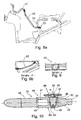
- FIG. 8 Another anti-theft device (98) according to the invention, is shown in figures 8, 9, and 10 , incorporating the means to secure it to a fixed point (22).
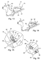
- Anther anti-theft device (74) according to the invention, is shown in figures 13, 14, 15, and 16 incorporating the means to secure it to a fixed point (22).
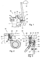
- the anti-theft device (62) comprises, as shown in figures 1 to 3 , a terminal, (23), with one end threaded onto stud bolt (30) that is welded (30) to a frame tube (20), part of the stud (30) projecting from the tube (20) enabling the terminal (23) to be threaded onto it, which in one of the possible embodiments, as shown in figure 3 .
- This has an inner cavity (75) at its lower end, cylindrical in shape, to immobilise to a fixing pivot (76) which is on one of the ends of the chain (17) with links (27) ball joints or the like.
- the terminal, (23) incorporates on its side a stub (26) so that it is possible to immobilise onto it a terminal, (24), inside which is a cylindrical cavity (77) with the lock, (25), and a second interior cavity (78) for locking a fixing terminal (79), fitted to one of the ends of the chain (19), as may be seen in figure 3 .
- the functionality of the assembly formed by a fixed point (22) and an anti-theft device in a version (62) shown in figures 1 and 2 is to enable the anti-theft device (72), to immobilise the vehicle (10) to a post (15) of a street lamp (14), the lamp having (14) a column (15) and a light (16) located on its upper end, with the chain (19) secured by the aforementioned means to the terminal, (24) and this in turn secured (24) to the terminal, (23) as described before the fixed point (22).
- the chain (17) joins the handlebar (12) to the tubular structure (13).
- the anti-theft device (72) comprises, as may be seen in figures 4 to 7 , a terminal, (57) preferably cylindrical, the bottom part of which has a stud (78) to which a nut is threaded (28) welded to a plate (36), and (36) to a frame tube (20) forming a fixed point (22), the inside of the terminal (57) having a cavity (79), into which a bush or fixing pivot (58) is secured by known means to the end of a conventional chain (17) with links (27), see figure 4 .
- a terminal, (57) is secured a (34) to which a chain may be attached, as in (19).
- the anti-theft device (72) thus comprises, as shown in figure 5 , a terminal, (35), preferably cylindrical, the lower part of which has a cavity (79) also cylindrical and of a smaller diameter, threaded inside, to screw onto a stud bolt (30), welded to a frame tube (20) with a bead weld (29) securing the threaded part with a pin (31) that is inserted in a hole (64) .
- a terminal, (35) preferably cylindrical, the lower part of which has a cavity (79) also cylindrical and of a smaller diameter, threaded inside, to screw onto a stud bolt (30), welded to a frame tube (20) with a bead weld (29) securing the threaded part with a pin (31) that is inserted in a hole (64) .
- the pivot (80) has a slot (32) for housing a circlip (33), which once placed on the pivot (80) in the cavity (81), the circlip (33) opens and blocks the pivot (80) when it penetrates (33) the inner slot (32) of the terminal, (35).
- the anti-theft device in another version (98) shown in figures 8a, 8b, 9 and 10 comprises a tubular structure (60) formed by a right-hand part (46) of a vertical cylindrical shape open at one of its ends the upper closed, and a left-hand part (45) also horizontally cylindrical, the right-hand part (46) incorporates a retaining terminal (49).
- the retaining terminal (49) which by one of its ends is threaded to the stud (30), which welded to the frame tube (20) as may be seen in figure 9 .
- Said retaining terminal (49) is immobilised in the right-hand part (46) by a circlip (42), which is placed in immobilisation position in a slot (51), as may be seen in figure 10 .
- the anti-theft device in another version (63), see figure 11 comprises a main bush (37) which is in turn (37) formed by a cylindrical part (38) that extends downwards in a truncated cone part (39), and between parts (38-39) there is a slot (51), see figure 12 to hold the circlip (42), which opens when entering the slot (51) immobilising the main bush inside the cavity (82), of the right-hand part (46) of the tubular structure (60), see detail "b" in figure 11 .
- the stud (30) is threaded to the upper part of the main bush (37), immobilising (30) to (37) with a nut (85), see figure 12 .
- the anti-theft device (74) comprises a main bush (70) to which a the secondary bush (71) is incorporated by adequate means, leaving a slot (55) between (70-71), so the bush (71) can turn with regard to the main bush (70), securing to said secondary bush (71) the terminal, (56), joined (56) to one of the ends of the chain (52).
- the secondary bush (71) is fitted to the main bush (70) by the recess (83) in the upper part of the bush main (70).
- the anti-theft device (74) as shown in figure 15 is threaded onto the nut (28) of the fixed point (22), located on the frame tube (20), the chain in active situation (52) immobilising the handlebar (12), as may be seen in figure 13 by one of its ends thanks to the fixing pivot (53) and lock, (54) to the frame tube (20), while in standby position, as can be seen in figure 14 the fixing support (53) it secured to a point on any part of the vehicle chassis.
- Figures 17 and 18 show the features of a anti-theft device in version (99), comprising a bush (86) formed by an upper part (87) and a lower part (88), in the upper part (87), as can be seen in figure 18 , is fitted a plate (66) by the stud bolt (68) to which the protective plug is threaded (67), joining the bush (86) to the frame tube (20) with the stud (30), the upper part of which (30) is secured to (20) by welding (29), and by the upper part, the stud bolt (30) is screwed onto the lower side (88) of the bush (86).
- the chain (52) is fitted by one of its ends to the fixing terminal (56) and this is secured to the plate (66) by a pin (not illustrated).
- an anti-theft device in another version (90) see figure 19 , has a stud bolt (30) welded on one end to the frame tube (20), while the other end is screwed into the cavity (91), of the lower part (92) of a bush (94), while the upper part (93) is joined to a terminal, (56) by means of a lug (95) and a pin (96), in turn the terminal, (56) receives one end of the chain (52).
- the parts (92-93) of the bush (94) are joined with the stud bolt (97).
- the bush (100) has a cylindrical body (101) with flat upper and lower end (102-103), fitting to the upper base (102) and in the central orifice, (104) it contains, the support (111), the side of the cylindrical body (101), there are holes (119-141) opposite each other, to fit a stub (105) and a button lock (116) respectively, as may be seen in figure 22 .
- the body of the bush (100) may adopt other exterior configurations in addition to cylindrical without altering its functionality.
- the support (111), as may be seen in figure 20 through the hole (113), allows the mounting of the corresponding chain with links or similar (not depicted in the illustrations) in the hole (113), that joins the fixed point through the bush (100) and this in turn to the vehicle chassis or a resistant structure of the same, with the handlebar of the vehicle, or with an element of street furniture, to avoid the vehicle being loaded onto a truck or similar for robbery, even though the handlebar is immobilised.
- Figures 20 and 21 also show the design of this support (111), which includes a flat head (112) where the mentioned hole is located (113), extending downwards (112) with an extension (114) of circular perimeter that continues with a special thread with several diameters (115), which (115) fits into the cavity (121) on the inside of the cylindrical body (101) of the bush (100), as can be seen in figure 22 .
- the stub (105) which is shown in cross-section in figure 3 , has a head (106) with a cavity (107) designed for an Allen key or the like for fitting onto the body of the bush (100), this head (106) extending in a narrowing (108), that extends to a cylindrical part (109), and an truncated cone area (110), that in turn extends to another truncated cone section (121) that fits in the hole (119) of the body (101).
- the bush (100) To fit the bush (100), it is secured to the tubular structure or chassis of the vehicle by means of the hole (104) in the lower end of the body (101), then the support (111) is inserted into the cavity (121) by the upper end of the body (101), then the stub (105) is threaded in the hole (119) secured to the support (111), and finally the user fits the button lock (116) in the hole (141), completely locking the assembly and it is ready to act as a fixed point of an chain joined to the support (112) through the hole (113).
- the fixed point is formed by the bush (130), which includes a head (131) and a cylindrical body (132).
- the body (132) has on its upper base, a cavity (126), in which the cylindrical portion (122) of the head (131) fits, and in the lower base (127) there is a projection (128).
- the head (131) is depicted in detail in figures 25 and 26 , and is designed to have an interior cavity (133), machined with a circular slot (134), which (134) has a recess (135), the slot in turn (134) extends inside and downwards in cylindrical cavities of different diameters and lengths (136-139), and on the outside thy extend down in cylindrical portions (122-123-124), and between the portions (123-124) there is a circular cavity (169), to fit the seal or ring (125), ending the head (131) in a truncated conical portion (170) of little height, as shown in figure 26 .
- the bush (130) is fitted to the tubular structure of a vehicle of two or more wheels (Not depicted in the figures), with a screw (140) that penetrates the interior cavity (139) as can be seen in figure 25 , and the head (131) is retained on the cylindrical body (132) with the aid of the seal (125), that expands on the inside of the circular cavity (142) stopping the bush from detaching (130) from the tubular structure or chassis of the vehicle (not represented in the illustrations).
- the bush (143) includes the head (144) and the cylindrical body (145) of said bush (143), fitting to the latter (143) and in its side the stub (105).
- the cylindrical body (145) of the bush (143) has a hole (146) on its side, for fitting the stub (105).
- the formal and functional features of the head and the cylindrical body (144-145) are the same as described for the head and cylindrical body (131-132), so the cylindrical body (145) is versatile and allows one or two anchoring points in a single fixed point.
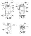
- the bush (147) as may be seen in figures 30 to 33 , comprises a cylindrical body (148) machined so that its upper part, the end (151) has a cavity (167) in which a head (149) is fitted, which fits into the cavity (150) on the body (148) of the bush (147).
- the bush in turn (147) and its body (148) are immobilised to the tubular structure of the vehicle (Not represented in the figures) by the lower end (153) using suitable means, having made a ridge (168) in this base (153).
- Figure 32 shows how the head (149) is immobilised in the cavity (150) designed on the inside of the body (148), having made in it (148) an inner circular slot (152), into which the ridge of circular perimeter (154) if fitted by pressure, guiding the entry of the head (149) in the cavity (150) by the slope (155).
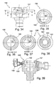
- any head of described above e.g., the one distinguished as (156) has had two slots (157) machined inside, instead of one slot such as in head (131) shown in figure 25 , thus, if someone tries to break the fixed point, and pull off one end of the head chain (156) see figures 34 and 39 which have the annular body (171) and a tab (172), the force needed to do this is much greater, and the possibilities of turning the chain and its annular body end (171) to free it from the head (156) and the slots (157), is also impeded with a sealing (158), so that un single shaft (159) that is a part of said sealing (158) and that slides through the passage (173) locking the tab (160), that forms a part of the annular bodies (161) present in the end of the chain (Not represented in the figures), but if these annular bodies (161) in figures 16 to 18 in different positions, and in figure 39 , which shows how the shaft (159) when it slides along channel (162),
- the head in this case (163) in contrast to the previous head (156), the head in this case (163) includes on its side a stub (164), and the lock (165) of a different type from that shown in figure 39 , but with the same functionality, which is none other than by means of the lug (166) sliding along the passage (167), to lock the tab (160) of the annular bodies (161) that fit into the slots (157).
- the annular bodies (161) can be locked through a shaft (180) linked by its upper end to a cable, (179) sliding in a sheath (182), so that when the user closes the anti-theft device using this cable, (179) this will pull the shaft (180) against the expansion action of the spring (181), sliding (180) through the hole (178) on the body of the head (163) freeing the annular bodies (161) and with is the corresponding chain (Not represented in the figures).
- the head (189) it has been machined inside to fit the support (169), on the tab of which (170) one end of a chain a chain with links is fitted (Not represented in the figures).
- the support (169) has body with annular ribs (171-172) that fit into the annular recesses (173-174).
Landscapes
- Engineering & Computer Science (AREA)
- Mechanical Engineering (AREA)
- Steering Devices For Bicycles And Motorcycles (AREA)
- Lock And Its Accessories (AREA)
- Automatic Cycles, And Cycles In General (AREA)
Claims (23)
- Eine Diebstahlsicherungsvorrichtung bestehend aus einem Fahrzeug mit einem Rahmen und einem Lenker, wobei der Lenker dazu vorbereitet ist, mit mechanischen Mitteln (23, 27) in Form eines Anschlusses und einer konventionellen Kette mit Kettengliedern an einem Befestigungspunkt am Fahrgestell gesichert zu werden, wobei der Befestigungspunkt einen Stehbolzen (30) umfasst, der durch eine Öffnung in den Rohrrahmen des Fahrzeugs eingesetzt ist und mit dem Rahmen verschweißt ist, wobei dieser Stehbolzen aus dem Rahmen hervorsteht, dadurch gekennzeichnet, dass diese mechanischen Mittel des Weiteren ein Anschlussteil (23) umfassen, wovon eine Seite auf den Stehbolzen (30) geschraubt ist, wobei das Anschlussteil (23) auf seiner Seite einen Stutzen (26) aufweist, wobei dieser Stutzen (26) für den Anschluss an ein zweites Anschlussteil (24) vorbereitet ist, wobei dieses zweite Anschlussteil (24) für die Aufnahme des Anschlussteils (79) einer Kette (19) vorbereitet ist.
- Eine Diebstahlsicherungsvorrichtung gemäß Anspruch 1, dadurch gekennzeichnet, dass die mechanischen Mittel ein vorzugsweise zylindrisches Anschlussteil (57) umfassen, an dessen Unterseite sich ein Bolzen (78) befindet, auf den eine Mutter (28) geschraubt wird, die an einer Platte (36) angeschweißt ist, wobei diese Platte (36) ihrerseits an einem Fahrgestellrohr (20) angeschweißt ist, das Teil eines Rohrrahmens (13) ist und einen Befestigungspunkt bildet, und wobei das Anschlussteil (57) einen Hohlraum (79) zur Aufnahme einer Hülse bzw. eines Befestigungszapfen (58) hat, wobei der Befestigungszapfen (58) mit bekannten Mitteln am Ende einer konventionellen Kette (17) mit Kettengliedern (27) der mechanischen Mittel befestigt ist.
- Eine Diebstahlsicherungsvorrichtung gemäß Anspruch 2, dadurch gekennzeichnet, dass sich auf der Seite des Anschlussteils (57) ein Befestigungszapfen (34) befindet, der zur Aufnahme eines Anschlussteils einer Kette (19) dient.
- Eine Diebstahlsicherungsvorrichtung gemäß Anspruch 1, dadurch gekennzeichnet, dass die mechanischen Mittel eine Rohrkonstruktion (60) umfassen, die die durch ein rechtes Teil (46) mit einer vertikal zylindrischen Form, das auf einer Seite offen und an der Oberseite geschlossen ist, und ein linkes Teil (45) mit einer horizontal zylindrischen Form gebildet wird, wobei das rechte Teil (46) einen Arretieranschluss (49) zur Aufnahme eines Anschlussteils einer zweiten Kette aufweist.
- Eine Diebstahlsicherungsvorrichtung gemäß Anspruch 4, dadurch gekennzeichnet, dass die Rohrkonstruktion (60) einen Hohlraum (82) zur Aufnahme des Arretieranschlusses (49) umfasst, der auf einer Seite auf den Bolzen (30) geschraubt ist, wobei dieser Arretieranschluss (49) im rechten Teil (46) der Rohrkonstruktion (60) durch einen Sprengring (42) arretiert wird, der sich in Fixierungsposition in einer Nut (51) im Hohlraum (82) befindet.
- Eine Diebstahlsicherungsvorrichtung gemäß Anspruch 1, dadurch gekennzeichnet, dass die mechanischen Mittel des Weiteren ein Anschlussteil (56) umfassen, das zur Aufnahme eines Endes der Kette (52) dient, und dass an diesem Anschlussteil (56) eine Sekundärhülse (71) befestigt wird, die sich an einer Haupthülse (70) befindet, wobei eine Nut (55) zwischen (70-71) vorhanden ist, damit die Hülse (71) in Bezug zur Haupthülse (70) drehen kann, und wobei die Sekundärhülse (71) durch die Auskehlung (83) an der Oberseite der Haupthülse (70) an der Haupthülse (70) befestigt ist.
- Eine Diebstahlsicherungsvorrichtung gemäß Anspruch 1, dadurch gekennzeichnet, dass die mechanischen Mitteln des Weiteren ein Anschlussteil (56) umfasst, das zur Aufnahme der Kette (52) auf einer seiner Seiten dient, und dass das Anschlussteil mit einem Stift an der Platte (66) befestigt ist, wobei die Platte zur Befestigung an der Oberseite (87) einer Hülse (86), eines Stehbolzens (68) vorbereitet ist, auf den der Schutzstopfen (67) geschraubt wird, wobei die Hülse (86) am Rahmenrohr (20) mit dem Bolzen (30) verbunden wird, dessen Oberseite (30) durch Schweißen (29) mit (20) verbunden ist, und an der Oberseite ist der Stehbolzen (30) in die Unterseite (88) der Hülse (86) geschraubt.
- Eine Diebstahlsicherungsvorrichtung gemäß Anspruch 1, dadurch gekennzeichnet, dass der Stehbolzen (30) auf der einen Seite am Rahmenrohr (20) verschweißt ist, und das andere Ende in den Hohlraum (91) an der Unterseite (92) einer Hülse (94) geschraubt ist, während die Oberseite (93) mittels einer Öse (95) und einem Stift (96) mit einem Anschlussteil (56) verbunden ist, wobei das Anschlussteil (56) zur Aufnahme eines Endes der Kette (52) dient, wobei die Teile (92-93) der Hülse (94) mit dem Stehbolzen (97) verbunden werden.
- Eine Diebstahlsicherungsvorrichtung gemäß Anspruch 1, dadurch gekennzeichnet, dass der Befestigungspunkt eine Hülse (100) mit zylindrischem Körper (101) mit flacher Ober- und Unterseite (102-103) und mit einer mittleren Öffnung (104) umfasst, die an ihrer Unterseite an der Rohrkonstruktion oder am Fahrgestell des Fahrzeugs befestigt wird, und an ihrer Oberseite zur Aufnahme einer Halterung (111) dient, wobei die Halterung (111) die Montage der entsprechenden Kette mit Kettengliedern in der Öffnung (113) ermöglicht, und den Befestigungspunkt über die Hülse (100) daran befestigt, und wobei die Seite des zylindrischen Körpers (101) des Weiteren sich gegenüber liegende Öffnungen (119-141) zum Befestigen eines Stutzens (105) und eines Knopfschlosses (116) umfasst.
- Eine Diebstahlsicherungsvorrichtung gemäß Anspruch 9, dadurch gekennzeichnet, dass die Halterung (111) ein flaches Kopfstück (112) aufweist, worin sich die Öffnung (113) befindet, die sich nach unten (112) mit einer Verlängerung (114) des kreisförmigen Umfangs erstreckt, und durch ein Spezialgewinde mit unterschiedlichen Durchmessern (115) fortgesetzt wird, das (115) in den Hohlraum (121) auf der Innenseite des zylindrischen Körpers (101) der Hülse (100) passt.
- Eine Diebstahlsicherungsvorrichtung gemäß Anspruch 9, dadurch gekennzeichnet, dass der Stutzen (105) einen Kopf (106) mit einem Hohlraum (107) zum Einsetzen eines Innensechskantschlüssels o. ä. in den Körper der Hülse (100) aufweist, wobei sich dieser Kopf (106) mit einer Verjüngung (108) verlängert wird, die sich in einen zylindrischen Teil (109) und einen kegelstumpfförmigen Bereich (110) erstreckt, der sich wiederum in einen weiteren kegelstumpfförmigen Abschnitt (121) erstreckt, der in die Öffnung (119) des Körpers (101) passt.
- Eine Diebstahlsicherungsvorrichtung gemäß Anspruch 1, dadurch gekennzeichnet, dass der Befestigungspunkt die Hülse (130) umfasst, die einen Kopf (131) und einen zylindrischen Körper (132) aufweist, der auf der Oberseite einen Hohlraum (126) aufweist, worin der zylindrische Abschnitt (122) des Kopfs (131) passt, und an der Unterseite (127) befindet sich ein Überstand (128).
- Eine Diebstahlsicherungsvorrichtung gemäß Anspruch 12, dadurch gekennzeichnet, dass der Kopf (131) so konstruiert ist, dass er auf seiner Innenseite den Hohlraum (133) aufweist, in die eine Ringnut (134) gearbeitet ist, wobei (134) eine Auskehlung (135) aufweist, und wobei sich die Nut (134) ihrerseits innen und in Abwärtsrichtung in zylindrische Hohlräume unterschiedlicher Durchmesser und Längen (136-139) erstreckt, und an der Außenseite erstrecken sie sich in Abwärtsrichtung in zylindrischen Abschnitten (122-123-124), und zwischen den Abschnitten (123-124) befindet sich ein kreisförmiger (169) für die Montage der Dichtung oder des Rings (125), wobei der Kopf (131) in einem kegelstumpfförmigen Abschnitt (170) geringer Höhe endet.
- Eine Diebstahlsicherungsvorrichtung gemäß Anspruch 12, dadurch gekennzeichnet, dass die Hülse (130) mit einer Schraube (140) an der Rohrkonstruktion eines Fahrzeugs mit zwei oder mehr Rädern (in den Abbildungen nicht dargestellt) befestigt wird, die in den inneren Hohlraum (139) eingesetzt ist, wie dies in der Abb. 6 zu erkennen ist, und wobei der Kopf (131) mittels der Dichtung (125) auf dem zylindrischen Körper (132) gehalten wird, die sich an der Innenseite des kreisförmigen Hohlraums (142) befindet, und verhindert, dass sich die Hülse von der Rohrkonstruktion oder vom Fahrgestell des Fahrzeugs löst.
- Eine Diebstahlsicherungsvorrichtung gemäß Anspruch 1, dadurch gekennzeichnet, dass der Befestigungspunkt die Hülse (143) umfasst, die den Kopf (144) und den zylindrischen Körper (145) der Hülse (143) aufweist, wobei an der Hülse (143) und auf ihrer Seite der Stutzen (105) befestigt wird, wobei der zylindrische Körper (145) der Hülse (143) seitlich eine Öffnung (146) zum Befestigen des Stutzens (105) aufweist.
- Eine Diebstahlsicherungsvorrichtung gemäß Anspruch 1, dadurch gekennzeichnet, dass der Befestigungspunkt die Hülse (147) umfasst, die einen derartig bearbeiteten zylindrischen Körper (148) aufweist, dass ihre Oberseite (151) einen Hohlraum (167) aufweist, in den ein Kopf (149) montiert wird, der in den Hohlraum (150) am Körper (148) der Hülse (147) passt, wobei die Hülse (147) und ihr Körper (148) mit geeigneten Mitteln an der Unterseite (153) des Fahrzeugs fixiert ist, wozu sich an dieser Basis (153) eine Rippe (168) befindet.
- Eine Diebstahlsicherungsvorrichtung gemäß Anspruch 16, dadurch gekennzeichnet, dass der Kopf (149) im Hohlraum (150) auf der Innenseite des Körpers (148) fixiert wird, wozu sich darin eine Ringnut (152) befindet, in die die Rippe mit ringförmigem Umfang (154) auf Druck eingepresst wird, wobei das Einsetzen des Kopfs (149) in den Hohlraum (150) durch die Flanke (155) geführt wird.
- Eine Diebstahlsicherungsvorrichtung gemäß Anspruch 16, dadurch gekennzeichnet, dass in die Innenseite des Kopfs die Nuten (157) gearbeitet sind, wodurch wenn jemand versucht, den Befestigungspunkt zu brechen und ein Ende der Kette (156) zu trennen, der erforderliche Kraftaufwand dazu sehr viel größer ist, und die Möglichkeit zum Drehen der Kette und ihres ringförmigen Abschlussstücks (171), um sie vom Kopf (156) und den Nuten (157) zu lösen, wird mit einer Dichtung (158) verhindert, wobei eine einzelne Welle (159), die Teil der Dichtung (158) ist, und durch den Kanal (173) gleitet, und die Raste (160) arretiert, die ein Teil der vorhandenen ringförmigen Körper (161) am Ende der Kette ist.
- Eine Diebstahlsicherungsvorrichtung gemäß Anspruch 16, dadurch gekennzeichnet, dass der Kopf auf seiner Seite einen Stutzen (164) und das Schloss (165) aufweist, das mittels der Öse (166) entlang des Kanals (167) gleitet, um die Raste (160) der ringförmigen Körper (161), die in die Nuten (157) im Kopf (163) greift, zu arretieren.
- Eine Diebstahlsicherungsvorrichtung gemäß Anspruch 1, dadurch gekennzeichnet, dass der Befestigungspunkt die Hülse umfasst, in die ein Kopf (168) passt, der eine Halterung (169) aufweist, worin sich eine Halterung (169) befindet, weil die Innenseite des Körpers des Kopfs (168) einen Hohlraum mit ringförmigen Auskehlungen (173-174) aufweist.
- Eine Diebstahlsicherungsvorrichtung gemäß Anspruch 20, dadurch gekennzeichnet, dass die Halterung (169) einen zylindrischen Körper aufweist, dessen Oberseite mit einer Raste (170) verlängert wird, und dass sich an der Innenseite des Körpers ringförmige Rippen (171-172) befinden.
- Eine Diebstahlsicherungsvorrichtung gemäß Anspruch 20, dadurch gekennzeichnet, dass der Kopf (168) auf seiner Seite ein Schloss (175) und eine Stutzen (105) aufweist, wobei sich die Halterung (169) durch eine Welle (176) dieses Schlosses bewegt, (165) die rechts und links des Kanals (177) gleitet.
- Eine Diebstahlsicherungsvorrichtung gemäß Anspruch 20, dadurch gekennzeichnet, dass der Körper des Kopfs (163) eine Öffnung (178) aufweist, in die eine Welle (180) eingesetzt wird, die von einer Feder (181) umgeben ist, wobei das obere Ende der Welle (180) an dem von einem Mantel (182) umgebenen Kabel (179) verbunden ist.
Applications Claiming Priority (3)
| Application Number | Priority Date | Filing Date | Title |
|---|---|---|---|
| ES200930917A ES2358659B1 (es) | 2009-10-28 | 2009-10-28 | Punto fijo para dispositivo antirrobo para vehículos de dos o más ruedas. |
| ES201031567A ES2381239B1 (es) | 2010-10-26 | 2010-10-26 | MEJORAS EN EL OBJETO DE LA PATENTE DE INVENCIÓN Nº 200930917 (0) POR: "PUNTO FIJO PARA DISPOSITIVO ANTIRROBO PARA VEHÍCULOS DE DOS O MÁS RUEDAS". |
| PCT/ES2010/070698 WO2011051532A1 (es) | 2009-10-28 | 2010-10-27 | Punto fijo para dispositivo antirrobo para vehículos de dos o mas ruedas |
Publications (3)
| Publication Number | Publication Date |
|---|---|
| EP2495158A1 EP2495158A1 (de) | 2012-09-05 |
| EP2495158A4 EP2495158A4 (de) | 2013-01-02 |
| EP2495158B1 true EP2495158B1 (de) | 2014-08-27 |
Family
ID=43921395
Family Applications (1)
| Application Number | Title | Priority Date | Filing Date |
|---|---|---|---|
| EP10826152.0A Not-in-force EP2495158B1 (de) | 2009-10-28 | 2010-10-27 | Festpunkt für eine diebstahlsicherungsvorrichtung für zwei- und mehrrädrige fahrzeuge |
Country Status (3)
| Country | Link |
|---|---|
| EP (1) | EP2495158B1 (de) |
| ES (1) | ES2524978T3 (de) |
| WO (1) | WO2011051532A1 (de) |
Family Cites Families (12)
| Publication number | Priority date | Publication date | Assignee | Title |
|---|---|---|---|---|
| US1991825A (en) * | 1933-09-21 | 1935-02-19 | William P Strickland | Anti-theft device |
| FR2263931A1 (en) * | 1974-03-15 | 1975-10-10 | Perret 3 Louis | Handle bar locking system for cycles - is extendable cable stowed inside the handle bar and lockable onto rear |
| US3910081A (en) * | 1974-05-07 | 1975-10-07 | David R Pender | Locking means for bicycles and the like |
| US3965709A (en) * | 1975-06-04 | 1976-06-29 | David P. Belke | Bicycle lock |
| ES295543Y (es) * | 1986-06-23 | 1989-05-01 | Colome Planas Fernando | Cable blindado antirrobo con dispositivo de bloqueo para motocicletas |
| FR2706411B1 (fr) * | 1993-06-11 | 1995-09-01 | Mbk Ind | Dispositif antivol pour véhicule et notamment, quoique non exclusivement pour véhicule à deux roues. |
| JP3455328B2 (ja) * | 1995-05-08 | 2003-10-14 | スズキ株式会社 | 自動二輪車の盗難防止装置 |
| IT1294495B1 (it) * | 1995-11-15 | 1999-04-12 | Aprilia Spa | Antifurto per veicoli a due ruote. |
| JPH1016844A (ja) * | 1996-07-03 | 1998-01-20 | Asahi Denso Kk | ワイヤ式ハンドルロック |
| JP4421751B2 (ja) * | 2000-05-12 | 2010-02-24 | 本田技研工業株式会社 | 車両のハンドルロック装置 |
| FR2879555A1 (fr) * | 2004-12-16 | 2006-06-23 | Peugeot Motocycles Sa | Systeme d'antivol pour vehicule a deux roues de type scooter |
| NL1034101C2 (nl) * | 2007-07-05 | 2009-01-06 | Batavus Bv | Fiets en slotkabel. |
-
2010
- 2010-10-27 EP EP10826152.0A patent/EP2495158B1/de not_active Not-in-force
- 2010-10-27 ES ES10826152.0T patent/ES2524978T3/es active Active
- 2010-10-27 WO PCT/ES2010/070698 patent/WO2011051532A1/es not_active Ceased
Also Published As
| Publication number | Publication date |
|---|---|
| WO2011051532A1 (es) | 2011-05-05 |
| WO2011051532A4 (es) | 2011-06-23 |
| EP2495158A1 (de) | 2012-09-05 |
| ES2524978T3 (es) | 2014-12-16 |
| EP2495158A4 (de) | 2013-01-02 |
Similar Documents
| Publication | Publication Date | Title |
|---|---|---|
| US9914332B2 (en) | Trailer hitch assembly for a vehicle | |
| US20060076752A1 (en) | Manually height adjustable and rotatable steering assembly for bicycles | |
| US8235411B2 (en) | Self-latching and locking trailer coupler | |
| US6889995B2 (en) | Hitch locking mechanism | |
| ZA200502849B (en) | Bicycle lock | |
| US5211042A (en) | Steering locking apparatus with tiltable steering mechanism | |
| US7431319B2 (en) | Hitch locking mechanism | |
| CA2477351A1 (en) | "push & lock" system with steel balls | |
| US5832753A (en) | Lock assembly | |
| AU2006100068A4 (en) | Tire lock | |
| CA2278821A1 (en) | Trailer kingpin locking apparatus | |
| EP2495158A1 (de) | Festpunkt für eine diebstahlsicherungsvorrichtung für zwei- und mehrrädrige fahrzeuge | |
| CA2939754A1 (en) | Coupling | |
| FR2475477A1 (fr) | Bequille pour porte-bagages de pavillon | |
| EP3530495B1 (de) | Entfernbare diebstahlsicherungsvorrichtung für anhängerkupplung | |
| KR19980087232A (ko) | 스티어링 컬럼에의 스티어링 휘일 고정장치 | |
| EP1944440A2 (de) | Vorrichtung zum Immobilisieren von Fahrzeugen an einem beweglichen Punkt oder anderen festen Punkten | |
| ES2358659B1 (es) | Punto fijo para dispositivo antirrobo para vehículos de dos o más ruedas. | |
| KR20000003809A (ko) | 고정식 높이조절링을 갖는 맨홀 | |
| US20040164518A1 (en) | Hitch locking mechanism | |
| FR2627445A1 (fr) | Mecanisme de blocage du volant pour vehicules automobiles | |
| EP1093430B1 (de) | Schlossvorrichtung, insbesondere für zweiradfahrzeuge | |
| EP2450269A1 (de) | Diebstahlschutzvorrichtung für motorräder, quads, roller und dergleichen | |
| WO2013110645A1 (fr) | Procédé de montage et ensemble de serrure pour ouvrant de véhicule automobile | |
| EP3808638B1 (de) | Kraftfahrzeug, das eine interne vorrichtung zum befestigen eines ersatzreifens umfasst |
Legal Events
| Date | Code | Title | Description |
|---|---|---|---|
| PUAI | Public reference made under article 153(3) epc to a published international application that has entered the european phase |
Free format text: ORIGINAL CODE: 0009012 |
|
| 17P | Request for examination filed |
Effective date: 20120425 |
|
| AK | Designated contracting states |
Kind code of ref document: A1 Designated state(s): AL AT BE BG CH CY CZ DE DK EE ES FI FR GB GR HR HU IE IS IT LI LT LU LV MC MK MT NL NO PL PT RO RS SE SI SK SM TR |
|
| A4 | Supplementary search report drawn up and despatched |
Effective date: 20121129 |
|
| RIC1 | Information provided on ipc code assigned before grant |
Ipc: B62H 5/00 20060101ALI20121123BHEP Ipc: B62H 5/04 20060101AFI20121123BHEP |
|
| 17Q | First examination report despatched |
Effective date: 20121211 |
|
| DAX | Request for extension of the european patent (deleted) | ||
| GRAP | Despatch of communication of intention to grant a patent |
Free format text: ORIGINAL CODE: EPIDOSNIGR1 |
|
| RIC1 | Information provided on ipc code assigned before grant |
Ipc: B62H 5/00 20060101ALI20131104BHEP Ipc: B62H 5/04 20060101AFI20131104BHEP |
|
| INTG | Intention to grant announced |
Effective date: 20131212 |
|
| GRAS | Grant fee paid |
Free format text: ORIGINAL CODE: EPIDOSNIGR3 |
|
| GRAA | (expected) grant |
Free format text: ORIGINAL CODE: 0009210 |
|
| AK | Designated contracting states |
Kind code of ref document: B1 Designated state(s): AL AT BE BG CH CY CZ DE DK EE ES FI FR GB GR HR HU IE IS IT LI LT LU LV MC MK MT NL NO PL PT RO RS SE SI SK SM TR |
|
| REG | Reference to a national code |
Ref country code: GB Ref legal event code: FG4D |
|
| REG | Reference to a national code |
Ref country code: CH Ref legal event code: EP |
|
| REG | Reference to a national code |
Ref country code: AT Ref legal event code: REF Ref document number: 684385 Country of ref document: AT Kind code of ref document: T Effective date: 20140915 |
|
| REG | Reference to a national code |
Ref country code: IE Ref legal event code: FG4D |
|
| REG | Reference to a national code |
Ref country code: DE Ref legal event code: R096 Ref document number: 602010018632 Country of ref document: DE Effective date: 20141009 |
|
| REG | Reference to a national code |
Ref country code: ES Ref legal event code: FG2A Ref document number: 2524978 Country of ref document: ES Kind code of ref document: T3 Effective date: 20141216 |
|
| REG | Reference to a national code |
Ref country code: AT Ref legal event code: MK05 Ref document number: 684385 Country of ref document: AT Kind code of ref document: T Effective date: 20140827 |
|
| REG | Reference to a national code |
Ref country code: LT Ref legal event code: MG4D |
|
| REG | Reference to a national code |
Ref country code: NL Ref legal event code: VDEP Effective date: 20140827 |
|
| PG25 | Lapsed in a contracting state [announced via postgrant information from national office to epo] |
Ref country code: BG Free format text: LAPSE BECAUSE OF FAILURE TO SUBMIT A TRANSLATION OF THE DESCRIPTION OR TO PAY THE FEE WITHIN THE PRESCRIBED TIME-LIMIT Effective date: 20141127 Ref country code: GR Free format text: LAPSE BECAUSE OF FAILURE TO SUBMIT A TRANSLATION OF THE DESCRIPTION OR TO PAY THE FEE WITHIN THE PRESCRIBED TIME-LIMIT Effective date: 20141128 Ref country code: FI Free format text: LAPSE BECAUSE OF FAILURE TO SUBMIT A TRANSLATION OF THE DESCRIPTION OR TO PAY THE FEE WITHIN THE PRESCRIBED TIME-LIMIT Effective date: 20140827 Ref country code: SE Free format text: LAPSE BECAUSE OF FAILURE TO SUBMIT A TRANSLATION OF THE DESCRIPTION OR TO PAY THE FEE WITHIN THE PRESCRIBED TIME-LIMIT Effective date: 20140827 Ref country code: PT Free format text: LAPSE BECAUSE OF FAILURE TO SUBMIT A TRANSLATION OF THE DESCRIPTION OR TO PAY THE FEE WITHIN THE PRESCRIBED TIME-LIMIT Effective date: 20141229 Ref country code: LT Free format text: LAPSE BECAUSE OF FAILURE TO SUBMIT A TRANSLATION OF THE DESCRIPTION OR TO PAY THE FEE WITHIN THE PRESCRIBED TIME-LIMIT Effective date: 20140827 Ref country code: NO Free format text: LAPSE BECAUSE OF FAILURE TO SUBMIT A TRANSLATION OF THE DESCRIPTION OR TO PAY THE FEE WITHIN THE PRESCRIBED TIME-LIMIT Effective date: 20141127 |
|
| PG25 | Lapsed in a contracting state [announced via postgrant information from national office to epo] |
Ref country code: CY Free format text: LAPSE BECAUSE OF FAILURE TO SUBMIT A TRANSLATION OF THE DESCRIPTION OR TO PAY THE FEE WITHIN THE PRESCRIBED TIME-LIMIT Effective date: 20140827 Ref country code: IS Free format text: LAPSE BECAUSE OF FAILURE TO SUBMIT A TRANSLATION OF THE DESCRIPTION OR TO PAY THE FEE WITHIN THE PRESCRIBED TIME-LIMIT Effective date: 20141227 Ref country code: RS Free format text: LAPSE BECAUSE OF FAILURE TO SUBMIT A TRANSLATION OF THE DESCRIPTION OR TO PAY THE FEE WITHIN THE PRESCRIBED TIME-LIMIT Effective date: 20140827 Ref country code: HR Free format text: LAPSE BECAUSE OF FAILURE TO SUBMIT A TRANSLATION OF THE DESCRIPTION OR TO PAY THE FEE WITHIN THE PRESCRIBED TIME-LIMIT Effective date: 20140827 Ref country code: AT Free format text: LAPSE BECAUSE OF FAILURE TO SUBMIT A TRANSLATION OF THE DESCRIPTION OR TO PAY THE FEE WITHIN THE PRESCRIBED TIME-LIMIT Effective date: 20140827 Ref country code: LV Free format text: LAPSE BECAUSE OF FAILURE TO SUBMIT A TRANSLATION OF THE DESCRIPTION OR TO PAY THE FEE WITHIN THE PRESCRIBED TIME-LIMIT Effective date: 20140827 |
|
| PG25 | Lapsed in a contracting state [announced via postgrant information from national office to epo] |
Ref country code: NL Free format text: LAPSE BECAUSE OF FAILURE TO SUBMIT A TRANSLATION OF THE DESCRIPTION OR TO PAY THE FEE WITHIN THE PRESCRIBED TIME-LIMIT Effective date: 20140827 |
|
| PG25 | Lapsed in a contracting state [announced via postgrant information from national office to epo] |
Ref country code: RO Free format text: LAPSE BECAUSE OF FAILURE TO SUBMIT A TRANSLATION OF THE DESCRIPTION OR TO PAY THE FEE WITHIN THE PRESCRIBED TIME-LIMIT Effective date: 20140827 Ref country code: EE Free format text: LAPSE BECAUSE OF FAILURE TO SUBMIT A TRANSLATION OF THE DESCRIPTION OR TO PAY THE FEE WITHIN THE PRESCRIBED TIME-LIMIT Effective date: 20140827 Ref country code: DK Free format text: LAPSE BECAUSE OF FAILURE TO SUBMIT A TRANSLATION OF THE DESCRIPTION OR TO PAY THE FEE WITHIN THE PRESCRIBED TIME-LIMIT Effective date: 20140827 Ref country code: SK Free format text: LAPSE BECAUSE OF FAILURE TO SUBMIT A TRANSLATION OF THE DESCRIPTION OR TO PAY THE FEE WITHIN THE PRESCRIBED TIME-LIMIT Effective date: 20140827 Ref country code: CZ Free format text: LAPSE BECAUSE OF FAILURE TO SUBMIT A TRANSLATION OF THE DESCRIPTION OR TO PAY THE FEE WITHIN THE PRESCRIBED TIME-LIMIT Effective date: 20140827 |
|
| REG | Reference to a national code |
Ref country code: DE Ref legal event code: R097 Ref document number: 602010018632 Country of ref document: DE |
|
| PG25 | Lapsed in a contracting state [announced via postgrant information from national office to epo] |
Ref country code: LU Free format text: LAPSE BECAUSE OF FAILURE TO SUBMIT A TRANSLATION OF THE DESCRIPTION OR TO PAY THE FEE WITHIN THE PRESCRIBED TIME-LIMIT Effective date: 20141027 Ref country code: PL Free format text: LAPSE BECAUSE OF FAILURE TO SUBMIT A TRANSLATION OF THE DESCRIPTION OR TO PAY THE FEE WITHIN THE PRESCRIBED TIME-LIMIT Effective date: 20140827 Ref country code: MC Free format text: LAPSE BECAUSE OF FAILURE TO SUBMIT A TRANSLATION OF THE DESCRIPTION OR TO PAY THE FEE WITHIN THE PRESCRIBED TIME-LIMIT Effective date: 20140827 |
|
| REG | Reference to a national code |
Ref country code: CH Ref legal event code: PL |
|
| PG25 | Lapsed in a contracting state [announced via postgrant information from national office to epo] |
Ref country code: BE Free format text: LAPSE BECAUSE OF NON-PAYMENT OF DUE FEES Effective date: 20141031 |
|
| PLBE | No opposition filed within time limit |
Free format text: ORIGINAL CODE: 0009261 |
|
| STAA | Information on the status of an ep patent application or granted ep patent |
Free format text: STATUS: NO OPPOSITION FILED WITHIN TIME LIMIT |
|
| GBPC | Gb: european patent ceased through non-payment of renewal fee |
Effective date: 20141127 |
|
| REG | Reference to a national code |
Ref country code: IE Ref legal event code: MM4A |
|
| PG25 | Lapsed in a contracting state [announced via postgrant information from national office to epo] |
Ref country code: CH Free format text: LAPSE BECAUSE OF NON-PAYMENT OF DUE FEES Effective date: 20141031 Ref country code: LI Free format text: LAPSE BECAUSE OF NON-PAYMENT OF DUE FEES Effective date: 20141031 |
|
| 26N | No opposition filed |
Effective date: 20150528 |
|
| REG | Reference to a national code |
Ref country code: FR Ref legal event code: PLFP Year of fee payment: 6 |
|
| PG25 | Lapsed in a contracting state [announced via postgrant information from national office to epo] |
Ref country code: IE Free format text: LAPSE BECAUSE OF NON-PAYMENT OF DUE FEES Effective date: 20141027 Ref country code: GB Free format text: LAPSE BECAUSE OF NON-PAYMENT OF DUE FEES Effective date: 20141127 |
|
| PGFP | Annual fee paid to national office [announced via postgrant information from national office to epo] |
Ref country code: ES Payment date: 20150929 Year of fee payment: 6 |
|
| PG25 | Lapsed in a contracting state [announced via postgrant information from national office to epo] |
Ref country code: SI Free format text: LAPSE BECAUSE OF FAILURE TO SUBMIT A TRANSLATION OF THE DESCRIPTION OR TO PAY THE FEE WITHIN THE PRESCRIBED TIME-LIMIT Effective date: 20140827 |
|
| PGFP | Annual fee paid to national office [announced via postgrant information from national office to epo] |
Ref country code: FR Payment date: 20150921 Year of fee payment: 6 |
|
| PG25 | Lapsed in a contracting state [announced via postgrant information from national office to epo] |
Ref country code: SM Free format text: LAPSE BECAUSE OF FAILURE TO SUBMIT A TRANSLATION OF THE DESCRIPTION OR TO PAY THE FEE WITHIN THE PRESCRIBED TIME-LIMIT Effective date: 20140827 |
|
| PGFP | Annual fee paid to national office [announced via postgrant information from national office to epo] |
Ref country code: IT Payment date: 20151029 Year of fee payment: 6 Ref country code: DE Payment date: 20151222 Year of fee payment: 6 |
|
| PG25 | Lapsed in a contracting state [announced via postgrant information from national office to epo] |
Ref country code: TR Free format text: LAPSE BECAUSE OF FAILURE TO SUBMIT A TRANSLATION OF THE DESCRIPTION OR TO PAY THE FEE WITHIN THE PRESCRIBED TIME-LIMIT Effective date: 20140827 Ref country code: MT Free format text: LAPSE BECAUSE OF FAILURE TO SUBMIT A TRANSLATION OF THE DESCRIPTION OR TO PAY THE FEE WITHIN THE PRESCRIBED TIME-LIMIT Effective date: 20140827 Ref country code: HU Free format text: LAPSE BECAUSE OF FAILURE TO SUBMIT A TRANSLATION OF THE DESCRIPTION OR TO PAY THE FEE WITHIN THE PRESCRIBED TIME-LIMIT; INVALID AB INITIO Effective date: 20101027 Ref country code: BE Free format text: LAPSE BECAUSE OF FAILURE TO SUBMIT A TRANSLATION OF THE DESCRIPTION OR TO PAY THE FEE WITHIN THE PRESCRIBED TIME-LIMIT Effective date: 20140827 |
|
| REG | Reference to a national code |
Ref country code: DE Ref legal event code: R119 Ref document number: 602010018632 Country of ref document: DE |
|
| REG | Reference to a national code |
Ref country code: FR Ref legal event code: ST Effective date: 20170630 |
|
| PG25 | Lapsed in a contracting state [announced via postgrant information from national office to epo] |
Ref country code: DE Free format text: LAPSE BECAUSE OF NON-PAYMENT OF DUE FEES Effective date: 20170503 Ref country code: FR Free format text: LAPSE BECAUSE OF NON-PAYMENT OF DUE FEES Effective date: 20161102 |
|
| PG25 | Lapsed in a contracting state [announced via postgrant information from national office to epo] |
Ref country code: IT Free format text: LAPSE BECAUSE OF NON-PAYMENT OF DUE FEES Effective date: 20161027 |
|
| PG25 | Lapsed in a contracting state [announced via postgrant information from national office to epo] |
Ref country code: ES Free format text: LAPSE BECAUSE OF NON-PAYMENT OF DUE FEES Effective date: 20161028 |
|
| PG25 | Lapsed in a contracting state [announced via postgrant information from national office to epo] |
Ref country code: MK Free format text: LAPSE BECAUSE OF FAILURE TO SUBMIT A TRANSLATION OF THE DESCRIPTION OR TO PAY THE FEE WITHIN THE PRESCRIBED TIME-LIMIT Effective date: 20140827 |
|
| PG25 | Lapsed in a contracting state [announced via postgrant information from national office to epo] |
Ref country code: AL Free format text: LAPSE BECAUSE OF FAILURE TO SUBMIT A TRANSLATION OF THE DESCRIPTION OR TO PAY THE FEE WITHIN THE PRESCRIBED TIME-LIMIT Effective date: 20140827 |
|
| REG | Reference to a national code |
Ref country code: ES Ref legal event code: FD2A Effective date: 20181113 |