EP2494342B1 - Brenngassensoren mit integrierten stützstrukturen - Google Patents
Brenngassensoren mit integrierten stützstrukturen Download PDFInfo
- Publication number
- EP2494342B1 EP2494342B1 EP10791004.4A EP10791004A EP2494342B1 EP 2494342 B1 EP2494342 B1 EP 2494342B1 EP 10791004 A EP10791004 A EP 10791004A EP 2494342 B1 EP2494342 B1 EP 2494342B1
- Authority
- EP
- European Patent Office
- Prior art keywords
- support
- combustible gas
- conductive
- gas sensor
- support member
- Prior art date
- Legal status (The legal status is an assumption and is not a legal conclusion. Google has not performed a legal analysis and makes no representation as to the accuracy of the status listed.)
- Active
Links
Images


Classifications
-
- G—PHYSICS
- G01—MEASURING; TESTING
- G01N—INVESTIGATING OR ANALYSING MATERIALS BY DETERMINING THEIR CHEMICAL OR PHYSICAL PROPERTIES
- G01N27/00—Investigating or analysing materials by the use of electric, electrochemical, or magnetic means
- G01N27/02—Investigating or analysing materials by the use of electric, electrochemical, or magnetic means by investigating impedance
- G01N27/04—Investigating or analysing materials by the use of electric, electrochemical, or magnetic means by investigating impedance by investigating resistance
- G01N27/14—Investigating or analysing materials by the use of electric, electrochemical, or magnetic means by investigating impedance by investigating resistance of an electrically-heated body in dependence upon change of temperature
- G01N27/16—Investigating or analysing materials by the use of electric, electrochemical, or magnetic means by investigating impedance by investigating resistance of an electrically-heated body in dependence upon change of temperature caused by burning or catalytic oxidation of surrounding material to be tested, e.g. of gas
-
- G—PHYSICS
- G01—MEASURING; TESTING
- G01N—INVESTIGATING OR ANALYSING MATERIALS BY DETERMINING THEIR CHEMICAL OR PHYSICAL PROPERTIES
- G01N27/00—Investigating or analysing materials by the use of electric, electrochemical, or magnetic means
- G01N27/26—Investigating or analysing materials by the use of electric, electrochemical, or magnetic means by investigating electrochemical variables; by using electrolysis or electrophoresis
- G01N27/416—Systems
- G01N27/4162—Systems investigating the composition of gases, by the influence exerted on ionic conductivity in a liquid
-
- G—PHYSICS
- G01—MEASURING; TESTING
- G01N—INVESTIGATING OR ANALYSING MATERIALS BY DETERMINING THEIR CHEMICAL OR PHYSICAL PROPERTIES
- G01N33/00—Investigating or analysing materials by specific methods not covered by groups G01N1/00 - G01N31/00
- G01N33/0004—Gaseous mixtures, e.g. polluted air
- G01N33/0009—General constructional details of gas analysers, e.g. portable test equipment
- G01N33/0011—Sample conditioning
- G01N33/0016—Sample conditioning by regulating a physical variable, e.g. pressure or temperature
-
- G—PHYSICS
- G01—MEASURING; TESTING
- G01N—INVESTIGATING OR ANALYSING MATERIALS BY DETERMINING THEIR CHEMICAL OR PHYSICAL PROPERTIES
- G01N33/00—Investigating or analysing materials by specific methods not covered by groups G01N1/00 - G01N31/00
- G01N33/0004—Gaseous mixtures, e.g. polluted air
- G01N33/0009—General constructional details of gas analysers, e.g. portable test equipment
- G01N33/0027—General constructional details of gas analysers, e.g. portable test equipment concerning the detector
-
- G—PHYSICS
- G01—MEASURING; TESTING
- G01N—INVESTIGATING OR ANALYSING MATERIALS BY DETERMINING THEIR CHEMICAL OR PHYSICAL PROPERTIES
- G01N33/00—Investigating or analysing materials by specific methods not covered by groups G01N1/00 - G01N31/00
- G01N33/0004—Gaseous mixtures, e.g. polluted air
- G01N33/0009—General constructional details of gas analysers, e.g. portable test equipment
- G01N33/0027—General constructional details of gas analysers, e.g. portable test equipment concerning the detector
- G01N33/0031—General constructional details of gas analysers, e.g. portable test equipment concerning the detector comprising two or more sensors, e.g. a sensor array
-
- G—PHYSICS
- G01—MEASURING; TESTING
- G01N—INVESTIGATING OR ANALYSING MATERIALS BY DETERMINING THEIR CHEMICAL OR PHYSICAL PROPERTIES
- G01N33/00—Investigating or analysing materials by specific methods not covered by groups G01N1/00 - G01N31/00
- G01N33/0004—Gaseous mixtures, e.g. polluted air
- G01N33/0009—General constructional details of gas analysers, e.g. portable test equipment
- G01N33/0027—General constructional details of gas analysers, e.g. portable test equipment concerning the detector
- G01N33/0036—General constructional details of gas analysers, e.g. portable test equipment concerning the detector specially adapted to detect a particular component
- G01N33/0047—Organic compounds
-
- G—PHYSICS
- G01—MEASURING; TESTING
- G01N—INVESTIGATING OR ANALYSING MATERIALS BY DETERMINING THEIR CHEMICAL OR PHYSICAL PROPERTIES
- G01N33/00—Investigating or analysing materials by specific methods not covered by groups G01N1/00 - G01N31/00
- G01N33/0004—Gaseous mixtures, e.g. polluted air
- G01N33/0009—General constructional details of gas analysers, e.g. portable test equipment
- G01N33/0073—Control unit therefor
-
- G—PHYSICS
- G01—MEASURING; TESTING
- G01N—INVESTIGATING OR ANALYSING MATERIALS BY DETERMINING THEIR CHEMICAL OR PHYSICAL PROPERTIES
- G01N33/00—Investigating or analysing materials by specific methods not covered by groups G01N1/00 - G01N31/00
- G01N33/22—Fuels; Explosives
- G01N33/225—Gaseous fuels, e.g. natural gas
Definitions
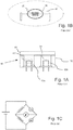
- a conventional combustible gas sensor 10 typically includes an element such as a platinum element wire or coil 20 encased in a refractory (for example, alumina) bead 30, which is impregnated with a catalyst (for example, palladium or platinum) to form an active or sensing element, which is sometimes referred to as a pelement 40, pellistor, detector or sensing element.
- a catalyst for example, palladium or platinum
- Active or sensing pelement 40 and compensating pelement 50 can, for example, be deployed within wells 60a and 60b of an explosion-proof housing 70 and can be separated from the surrounding environment by a flashback arrestor, for example, a porous metal frit 80.
- Porous metal frit 80 allows ambient gases to pass into housing 70 but prevents ignition of flammable gas in the surrounding environment by the hot elements.
- Such catalytic gas sensors are usually mounted in instruments which, in some cases, must be portable and, therefore, carry their own power supply. It is, therefore, desirable to minimize the power consumption of a catalytic gas sensor.
- the combustible gas sensor can also include a first catalyst support member in operative connection with the first conductive element, wherein the intermediate section of the first support element contacts the first catalyst support member to provide support for the first conductive element.
- the first support element passes through at least a portion of the first catalyst support.
- the first catalyst support member supports a catalyst thereon.
- the first catalyst support member has a volume less than a sphere having a diameter of 500 ⁇ m (wherein the volume of a sphere is calculated by the formula 4/3 ⁇ (D/2) 3 ).
- the first catalyst support member can have a volume no greater than a sphere having a diameter of no greater than 440 ⁇ m, or a diameter no greater than 300 ⁇ m.
- the combustible gas sensor can further include at least two electrically conductive contact members between which the first conductive element is connected.
- the contact members are in electrical connection with electronic circuitry.
- the first support element can, for example, include an alloy of at least one of tungsten, nickel, molybdenum or titanium with at least one of platinum, palladium, rhodium or iridium.
- the first support element includes a platinum-tungsten alloy.
- the combustible gas sensor can further include at least a second sensing element including a second conductive element having, for example, an average diameter less than 20 ⁇ m in electrical connection with the electronic circuitry.
- the combustible gas sensor can further include a second support element second support element including a first anchored end, a second anchored end and an extending intermediate section between the first anchored end and the second anchored end. The extending intermediate section of the second support element provides support for the second conductive element.
- the second support element can, for example, be in operative connection with the second conductive element to provide support therefor.
- the second support element can, for example, contact the second conductive element to provide support therefor.
- the second support element can, for example, exhibit a quotient calculated by dividing a tensile strength thereof in units of pounds per square inch or psi by a thermal conductivity thereof in units of watts/cm/°C of at least 250,000.
- the combustible gas sensor can further include a third support member to which the first anchored end of the second support element is anchored and a fourth support member to which the second anchored end of the first support element is anchored.
- the combustible gas sensor can also include a second catalyst support member in operative connection with the second conductive element, wherein the intermediate section of the second support element contacts the second catalyst support member to provide support for the second conductive element.
- the second support element can, for example, pass through at least a portion of the second catalyst support.
- the second catalyst support member supports a catalyst thereon.
- the second support element can, for example, include an alloy of at least one of tungsten, nickel, molybdenum or titanium with at least one of platinum, palladium or rhodium.
- the second support element includes a platinum-tungsten alloy.
- the second support element has an average diameter in the range of approximately 0.0005 inches to approximately 0.0025 inches.
- the second support element can, for example, have an average diameter of approximately 0.001 inches.
- the second sensing element can, for example, be used to compensate for ambient temperature changes.
- the first sensing element can, for example, be used to compensate for ambient temperature changes.
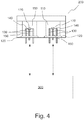
- catalyst support member 170 As a ceramic bead, an aluminum oxide suspension was fired onto coiled section 142. The resultant catalyst support member/ceramic bead 170 was impregnated with a catalyst. Although a bare wire comprising a catalytic material (such as platinum) can be used as a sensing element in certain embodiments of a combustible gas sensor, a catalyst support member 170 (such as a ceramic bead) provides increased surface area for one or more catalyst species.
- a catalytic material such as platinum
- Support element 160 thus increases durability while decreasing heat loss as compared to sensors including other support systems or support mechanisms.
- FIG. 3A illustrates signal responses to periodic inflow/spikes of 2.5% methane over a temperature range of -30 to +50°C.
- the trace labeled 1/20 (low power, compensation mode) sets forth data for a sensing element or detector operated at 1/20 the power of an active sensing element or detector, thereby providing a "temperature compensating" function as described above.
- Figure 3B illustrates sensor response calibrated to 50% LEL. Figure 3B also sets forth how temperature was varied over the time of the study.
- the sensing elements of the sensor can be switched between a high power/high temperature active mode and a low power/low temperature inactive or compensating mode over a wide range of periods.
- the period of cycling is limited (on the lower end) by the amount of time required to achieve equilibrium or steady state operation. Periods as low as, for example, 20 seconds were possible with the sensing elements tested. Much longer periods (for example, hours days, weeks, months or longer) are also possible.
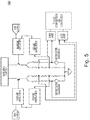
- Electronic circuitry 300 (see Figure 4 ), which is in electrical connection with contact posts 130 of each of detector assemblies 110, can effect automatic periodic switching between sensing element modes. Alternatively, switching between modes can be effected after a manually initiated or controlled event such as a power off/power on (or power cycling) procedure or event.
Landscapes
- Chemical & Material Sciences (AREA)
- Health & Medical Sciences (AREA)
- Life Sciences & Earth Sciences (AREA)
- Engineering & Computer Science (AREA)
- Analytical Chemistry (AREA)
- Immunology (AREA)
- Pathology (AREA)
- General Physics & Mathematics (AREA)
- General Health & Medical Sciences (AREA)
- Physics & Mathematics (AREA)
- Biochemistry (AREA)
- Medicinal Chemistry (AREA)
- Food Science & Technology (AREA)
- Combustion & Propulsion (AREA)
- Chemical Kinetics & Catalysis (AREA)
- Electrochemistry (AREA)
- Oil, Petroleum & Natural Gas (AREA)
- General Chemical & Material Sciences (AREA)
- Molecular Biology (AREA)
- Investigating Or Analyzing Materials By The Use Of Electric Means (AREA)
Claims (17)
- Sensor für entzündliche Gase (200), aufweisend:
mindestens ein erstes Abfühlelement, aufweisend ein erstes leitfähiges Element (140) mit einem durchschnittlichen Durchmesser kleiner als 20 µm, wobei ein erstes Ende des ersten leitfähigen Elements (140) an einem ersten leitfähigen Teil (130) befestigt ist, und ein zweites Ende des ersten leitfähigen Elements (140) an einem zweiten leitfähigen Teil (130) befestigt ist, wobei das erste leitfähige Teil (130) und das zweite leitfähige Teil (130) in elektrischer Verbindung mit einer elektronischen Schaltung (300) sind, wobei der Sensor für entzündliche Gase (200) des Weiteren aufweist:ein erstes und ein zweites Trägerteil (150) und ein erstes Trägerelement (160), das ein Metall oder eine Metallegierung aufweist, wobei das erste Trägerelement (160) ein erstes verankertes Ende, das an dem ersten Trägerteil (150) befestigt ist, ein zweites verankertes Ende, das an dem zweiten Trägerteil (150) befestigt ist, und ein Zwischensegment, das sich zwischen dem ersten verankerten Ende und dem zweiten verankerten Ende erstreckt, wobei das erste Trägerteil (150) und das zweite Trägerteil (150) von dem ersten leitfähigen Teil (130) und dem zweiten leitfähigen Teil (130) elektrisch isoliert sind,wobei das Zwischensegment in Kontakt mit dem ersten leitfähigen Element (140) ist und dieses trägt, wobei das erste Trägerelement (160) einen Quotienten, der durch Teilen von dessen Zugfestigkeit in der Einheit Pound per Square Inch oder psi (N/m2) durch dessen Wärmeleitfähigkeit in der Einheit Watt/cm/°C (Watt/m/Kelvin) berechnet wird, von mindestens 250.000 (17.236.875 (N/m2)/ (Watt/m/Kelvin)) zeigt, und wobei das erste Trägerelement (160) einen durchschnittlichen Durchmesser im Bereich von annähernd 0,0005 Inch (0,00127 cm) bis annähernd 0,0025 Inch (0,00635 cm) aufweist. - Sensor für entzündliche Gase (200) nach Anspruch 1, des Weiteren aufweisend mindestens ein zweites Abfühlelement, aufweisend ein zweites leitfähiges Element (140) mit einem durchschnittlichen Durchmesser kleiner als 20 µm, wobei ein erstes Ende des zweiten leitfähigen Elements (140) an einem dritten leitfähigen Teil (130) befestigt ist, und ein zweites Ende des ersten leitfähigen Elements (140) an einem vierten leitfähigen Teil (130) befestigt ist, wobei das dritte leitfähige Teil (130) und das vierte leitfähige Teil (130) in elektrischer Verbindung mit der elektronischen Schaltung (300) sind, wobei der Sensor für entzündliche Gase (200) des Weiteren ein zweites Trägerelement (160) aufweist, das ein Metall oder eine Metalllegierung aufweist,
wobei das zweite Trägerelement (160) des Weiteren ein erstes verankertes Ende, das an einem dritten Trägerteil (150) befestigt ist, und ein zweites verankertes Ende, das an einem vierten Trägerteil (150) befestigt ist, und ein Zwischensegment aufweist, welches sich zwischen dem ersten verankerten Ende des zweiten Trägerelements (160) und dem zweiten verankerten Ende des zweiten Trägerelements (160) erstreckt, wobei das dritte Trägerteil (150) und das vierte Trägerteil (150) elektrisch von dem dritten leitfähigen Teil (130) und dem vierten leitfähigen Element (130) isoliert sind,
wobei das Zwischensegment des zweiten Trägerelements (160) in Kontakt mit dem zweiten leitfähigen Element (140) ist und dieses trägt, wobei das zweite Trägerelement (160) einen Quotienten, der durch Teilen von dessen Zugfestigkeit in der Einheit Pound per Square Inch oder psi (N/m2) durch dessen Wärmeleitfähigkeit in der Einheit Watt/cm/°C (Watt/m/Kelvin) berechnet wird, von mindestens 250.000 (17.236.875 (N/m2)/(Watt/m/Kelvin)) zeigt, und wobei das zweite Trägerelement (160) einen durchschnittlichen Durchmesser im Bereich von annähernd 0,0005 Inch (0,00127 cm) bis annähernd 0,0025 Inch (0,00635 cm) aufweist. - Sensor für entzündliche Gase (200) nach Anspruch 1, wobei das erste Trägerelement (160) einen Quotienten, der durch Teilen von dessen Zugfestigkeit in der Einheit Pounds per Square Inch oder psi durch dessen Wärmeleitfähigkeit in der Einheit Watt/cm/°C berechnet wird, von mindestens 400.000 zeigt, und das zweite Trägerelement (160) einen Quotienten, der durch Teilen von dessen Zugfestigkeit in der Einheit Pounds per Square Inch oder psi durch dessen Wärmeleitfähigkeit in der Einheit Watt/cm/°C berechnet wird, von 400.000 zeigt.
- Sensor für entzündliche Gase nach Anspruch 1, wobei das erste leitfähige Element (140) einen durchschnittlichen Durchmesser kleiner als 12,5 µm aufweist.
- Sensor für entzündliche Gase (200) nach Anspruch 1, wobei das erste leitfähige Element (140) einen durchschnittlichen Durchmesser nicht größer als annähernd 10 µm aufweist.
- Sensor für entzündliche Gase (200) nach Anspruch 2, wobei das zweite leitfähige Element (140) einen durchschnittlichen Durchmesser kleiner als 20 µm aufweist.
- Sensor für entzündliche Gase (200) nach Anspruch 1 oder Anspruch 2, des Weiteren aufweisend ein erstes Katalysatorträgerteil (170) oder ein zweites Katalysatorträgerteil (170) in funktionaler Verbindung mit dem ersten leitfähigen Element (140) oder dem zweiten leitfähigen Element (140), wobei das Zwischensegment des ersten Trägerelements (160) oder des zweiten Trägerelements (160) in Kontakt mit dem ersten Katalysatorträgerteil (170) oder dem zweiten Katalysatorträgerteil (170) kommt, um das erste leitfähige Element (140) oder das zweite leitfähige Element (140) zu tragen, wobei das erste Katalysatorträgerteil (170) oder das zweite Katalysatorträgerelement (170) einen Katalysator darauf tragen.
- Sensor für entzündliche Gase (200) nach Anspruch 7, wobei das erste Trägerelement (160) oder das zweite Trägerelement (160) durch mindestens einen Anteil des ersten Katalysatorträgerteils (170) oder des zweiten Katalysatorträgerteils (170) führt.
- Sensor für entzündliche Gase (200) nach Anspruch 8, wobei das erste Katalysatorträgerteil (170) oder das zweite Katalysatorträgerteil (170) ein Volumen von weniger als einer Kugel mit einem Durchmesser von 500 µm aufweist.
- Sensor für entzündliche Gase (200) nach Anspruch 1 oder Anspruch 2, wobei das erste Trägerelement (160) oder das zweite Trägerelement (160) eine Legierung von mindestens einem von Wolfram, Nickel, Molybdän oder Titan mit mindestens einem von Platin, Palladium, Rhodium oder Iridium aufweist.
- Sensor für entzündliche Gase (200) nach Anspruch 1 oder Anspruch 2, wobei das erste Trägerelement (160) oder das zweite Trägerelement eine Platin-WolframLegierung (160) aufweist.
- Sensor für entzündliche Gase (200) nach Anspruch 10, wobei das erste leitfähige Element (140) oder das zweite leitfähige Element (140) einen durchschnittlichen Durchmesser nicht größer als annähernd 10 µm aufweist.
- Sensor für entzündliche Gase (200) nach Anspruch 1 oder Anspruch 2, wobei das erste Trägerelement (160) oder das zweite Trägerelement (160) eine Zugfestigkeit von mindestens 100.000 psi (6,8948 x 10⁸ N/m2) aufweist.
- Sensor für entzündliche Gase (200) nach Anspruch 1 oder Anspruch 2, wobei das erste Trägerelement (160) oder das zweite Trägerelement (160) eine Wärmeleitfähigkeit nicht größer als 0,5 Watt/cm/°C aufweist.
- Sensor für entzündliche Gase (200) nach Anspruch 2, wobei die elektronische Schaltung (300) vorgesehen ist, um zwischen einem ersten Modus, in dem das erste Abfühlelement in einem Modus mit höherem Energieverbrauch und das zweite Abfühlelement in einem Modus mit niedrigerem Energieverbrauch ist, und einem zweiten Modus zu wechseln, in dem das zweite Abfühlelement in einem Modus mit höherem Energieverbrauch und das erste Abfühlelement in einem Modus mit niedrigerem Energieverbrauch ist.
- Sensor für entzündliche Gase (200) nach Anspruch 15, wobei das zweite Abfühlelement in dem ersten Modus Umgebungstemperaturänderungen kompensiert, und das erste Abfühlelement in dem zweiten Modus Umgebungstemperaturänderungen kompensiert.
- Sensor für entzündliche Gase (200) nach Anspruch 16, wobei die elektronische Schaltung (300) vorgesehen ist, um periodisch zwischen dem ersten Modus und dem zweiten Modus umzuschalten.
Priority Applications (1)
| Application Number | Priority Date | Filing Date | Title |
|---|---|---|---|
| EP20208265.7A EP3809126B1 (de) | 2009-10-30 | 2010-10-29 | Brenngassensoren mit mehreren aktiven elementen |
Applications Claiming Priority (2)
| Application Number | Priority Date | Filing Date | Title |
|---|---|---|---|
| US25674909P | 2009-10-30 | 2009-10-30 | |
| PCT/US2010/054860 WO2011053866A1 (en) | 2009-10-30 | 2010-10-29 | Combustible gas sensors including integral support structures and combustible gas sensor with multiple active elements |
Related Child Applications (1)
| Application Number | Title | Priority Date | Filing Date |
|---|---|---|---|
| EP20208265.7A Division EP3809126B1 (de) | 2009-10-30 | 2010-10-29 | Brenngassensoren mit mehreren aktiven elementen |
Publications (2)
| Publication Number | Publication Date |
|---|---|
| EP2494342A1 EP2494342A1 (de) | 2012-09-05 |
| EP2494342B1 true EP2494342B1 (de) | 2020-11-25 |
Family
ID=43589982
Family Applications (2)
| Application Number | Title | Priority Date | Filing Date |
|---|---|---|---|
| EP20208265.7A Active EP3809126B1 (de) | 2009-10-30 | 2010-10-29 | Brenngassensoren mit mehreren aktiven elementen |
| EP10791004.4A Active EP2494342B1 (de) | 2009-10-30 | 2010-10-29 | Brenngassensoren mit integrierten stützstrukturen |
Family Applications Before (1)
| Application Number | Title | Priority Date | Filing Date |
|---|---|---|---|
| EP20208265.7A Active EP3809126B1 (de) | 2009-10-30 | 2010-10-29 | Brenngassensoren mit mehreren aktiven elementen |
Country Status (10)
| Country | Link |
|---|---|
| US (3) | US8826721B2 (de) |
| EP (2) | EP3809126B1 (de) |
| JP (1) | JP2013509594A (de) |
| KR (1) | KR101758755B1 (de) |
| CN (2) | CN104614414B (de) |
| AU (1) | AU2010313245B2 (de) |
| BR (1) | BR112012008468A2 (de) |
| CA (1) | CA2774467C (de) |
| RU (1) | RU2611074C2 (de) |
| WO (1) | WO2011053866A1 (de) |
Families Citing this family (30)
| Publication number | Priority date | Publication date | Assignee | Title |
|---|---|---|---|---|
| AU2010313245B2 (en) | 2009-10-30 | 2014-10-23 | Msa Technology, Llc | Combustible gas sensors including integral support structures and combustible gas sensor with multiple active elements |
| US9784755B2 (en) | 2011-10-14 | 2017-10-10 | Msa Technology, Llc | Sensor interrogation |
| US10908111B2 (en) | 2011-10-14 | 2021-02-02 | Msa Technology, Llc | Sensor interrogation |
| EP2766725B1 (de) | 2011-10-14 | 2018-05-23 | MSA Technology, LLC | Verfahren zum testen eines gassensors |
| US9562873B2 (en) | 2011-10-14 | 2017-02-07 | Msa Technology, Llc | Sensor interrogation |
| US9528957B2 (en) | 2011-10-14 | 2016-12-27 | Msa Technology, Llc | Sensor interrogation |
| EP2763468B1 (de) * | 2013-01-31 | 2017-08-30 | Sensirion AG | Tragbare Sensorvorrichtung mit einem Gassensor und Verfahren zum Betrieb davon |
| EP2762881A1 (de) * | 2013-01-31 | 2014-08-06 | Sensirion Holding AG | Tragbare Sensorvorrichtung mit einem Gassensor und Niedrigleistungsmodus |
| BR112015014188A8 (pt) | 2013-03-12 | 2019-10-22 | Msa Technology Llc | método para testar um sistema, sistema para detectar um gás alvo, sensor eletroquímico, método para a operação de um sistema de sensores |
| US10578573B2 (en) * | 2013-03-12 | 2020-03-03 | Msa Technology, Llc | Diagnostics for catalytic structures and combustible gas sensors including catalytic structures |
| EP2806266B1 (de) * | 2013-05-23 | 2017-06-14 | Honeywell International Inc. | Pellistor mit Einzelelement, der unempfindlich gegenüber internen und externen Störungen ist |
| DE102014018681B3 (de) * | 2014-12-18 | 2015-10-29 | Dräger Safety AG & Co. KGaA | Gassensor und Verfahren zur Herstellung eines Messelementes |
| CN118900405A (zh) | 2016-04-19 | 2024-11-05 | 工业科技有限公司 | 工作人员安全系统 |
| CA3215844A1 (en) * | 2016-09-08 | 2018-03-15 | Industrial Scientific Corporation | Combustible gas sensing element with cantilever support |
| US10234412B2 (en) | 2016-11-04 | 2019-03-19 | Msa Technology, Llc | Identification of combustible gas species via pulsed operation of a combustible gas sensor |
| US10627379B2 (en) | 2017-05-17 | 2020-04-21 | Msa Technology, Llc | Comparative diagnostics for catalytic structures and combustible gas sensors including catalytic structures |
| US10948469B2 (en) | 2017-05-17 | 2021-03-16 | Msa Technology, Llc | Dynamic comparative diagnostics for catalytic structures and combustible gas sensors including catalytic structures |
| JP2020523182A (ja) | 2017-06-11 | 2020-08-06 | エムエスエー テクノロジー, リミテッド・ライアビリティ・カンパニー | 硫黄化合物用フィルタ |
| CA3090715C (en) * | 2018-03-03 | 2024-04-23 | James SAWADA | Sensor and method for detecting combustible gas |
| US10900922B2 (en) | 2018-07-17 | 2021-01-26 | Msa Technology, Llc | Power reduction in combustible gas sensors |
| EP3827498A1 (de) | 2018-07-23 | 2021-06-02 | MSA Technology, LLC | Energiegewinnung aus stromschleifen |
| US11543396B2 (en) | 2019-06-11 | 2023-01-03 | Msa Technology, Llc | Gas sensor with separate contaminant detection element |
| US11268923B2 (en) | 2019-06-11 | 2022-03-08 | Msa Technology, Llc | Sensor for compositions which deposit upon a surface from a gaseous matrix |
| US11112378B2 (en) | 2019-06-11 | 2021-09-07 | Msa Technology, Llc | Interrogation of capillary-limited sensors |
| CN110782629A (zh) | 2019-10-31 | 2020-02-11 | 盟莆安电子(上海)有限公司 | 一种光电充电式气体检测报警仪 |
| US11703473B2 (en) | 2019-12-11 | 2023-07-18 | Msa Technology, Llc | Operation of combustible gas sensor in a dynamic mode with a constant resistance setpoint |
| US12478808B2 (en) | 2020-06-29 | 2025-11-25 | Dräger Safety AG & Co. KGaA | Monitoring system |
| DE102021111431A1 (de) | 2020-06-29 | 2021-12-30 | Dräger Safety AG & Co. KGaA | Überwachungssystem |
| US12292429B2 (en) | 2020-06-29 | 2025-05-06 | Dräger Safety AG & Co. KGaA | Monitoring system |
| CN114636885B (zh) * | 2022-05-12 | 2022-08-09 | 佛山速敏智能仪器科技有限公司 | 变压器在线检测系统和检测方法 |
Citations (1)
| Publication number | Priority date | Publication date | Assignee | Title |
|---|---|---|---|---|
| JPH08247984A (ja) * | 1995-03-14 | 1996-09-27 | Yazaki Corp | 接触燃焼式ガスセンサ |
Family Cites Families (25)
| Publication number | Priority date | Publication date | Assignee | Title |
|---|---|---|---|---|
| JPS5264587U (de) * | 1975-11-10 | 1977-05-12 | ||
| JPS52143993U (de) * | 1976-04-26 | 1977-10-31 | ||
| US4296399A (en) * | 1977-12-21 | 1981-10-20 | A-T-O Inc. | Microminiature palladium oxide gas detector and method of making same |
| JPS60125555A (ja) * | 1983-12-09 | 1985-07-04 | Matsushita Electric Works Ltd | ガス漏れ警報器 |
| US4533520A (en) | 1984-07-02 | 1985-08-06 | Mine Safety Appliances Company | Circuit for constant temperature operation of a catalytic combustible gas detector |
| DE3629483A1 (de) * | 1986-08-29 | 1988-03-10 | Westfaelische Berggewerkschaft | Verfahren und vorrichtung insbesondere zur messung der methan- und/oder co-volumenkonzentration im bergbau unter tage |
| JPH01109250A (ja) * | 1987-10-22 | 1989-04-26 | Toshiba Corp | ガスセンサ |
| GB2210980A (en) * | 1987-10-14 | 1989-06-21 | Draegerwerk Ag | Gas sensors |
| US4981369A (en) * | 1988-10-20 | 1991-01-01 | Murata Mfg. Co., Ltd. | Frost and dew sensor |
| JPH01308954A (ja) * | 1989-02-08 | 1989-12-13 | Fuji Electric Co Ltd | ガス漏れ警報器 |
| US4970898A (en) * | 1989-09-20 | 1990-11-20 | Rosemount Inc. | Pressure transmitter with flame isolating plug |
| US5599584A (en) | 1994-12-16 | 1997-02-04 | Mine Safety Appliances Company | Microminiature combustible gas sensor and method of fabricating a microminiature combustible gas sensor |
| US5780715A (en) * | 1996-10-23 | 1998-07-14 | Mine Safety Appliances Company | Combustible gas measuring sensor circuit |
| US6705152B2 (en) | 2000-10-24 | 2004-03-16 | Nanoproducts Corporation | Nanostructured ceramic platform for micromachined devices and device arrays |
| US6344174B1 (en) | 1999-01-25 | 2002-02-05 | Mine Safety Appliances Company | Gas sensor |
| GB2361997A (en) * | 2000-05-04 | 2001-11-07 | Bw Technologies Ltd | Combustible gas detection |
| US6663834B1 (en) * | 2000-10-27 | 2003-12-16 | Mine Safety Appliance Company | Catalytic sensor |
| JP3836440B2 (ja) * | 2002-05-13 | 2006-10-25 | 本田技研工業株式会社 | ガスセンサの劣化診断方法 |
| JP4578990B2 (ja) * | 2004-03-30 | 2010-11-10 | シチズンホールディングス株式会社 | ガスセンサ用外装構成体 |
| JP2006153598A (ja) * | 2004-11-26 | 2006-06-15 | Honda Motor Co Ltd | ガス検出装置およびガス検出素子の制御方法 |
| US7744818B2 (en) * | 2005-02-28 | 2010-06-29 | Honeywell International Inc. | Stationary phase materials for micro gas analyzer |
| GB0507895D0 (en) * | 2005-04-19 | 2005-05-25 | City Tech | Gas sensor assembly |
| JP5155546B2 (ja) * | 2006-10-11 | 2013-03-06 | 新コスモス電機株式会社 | 接触燃焼式ガス検知素子及びその製造方法 |
| US20090013759A1 (en) * | 2007-07-13 | 2009-01-15 | General Electric Company | Wobbe index sensor system |
| AU2010313245B2 (en) * | 2009-10-30 | 2014-10-23 | Msa Technology, Llc | Combustible gas sensors including integral support structures and combustible gas sensor with multiple active elements |
-
2010
- 2010-10-29 AU AU2010313245A patent/AU2010313245B2/en active Active
- 2010-10-29 KR KR1020127012147A patent/KR101758755B1/ko active Active
- 2010-10-29 US US12/916,370 patent/US8826721B2/en active Active
- 2010-10-29 JP JP2012537151A patent/JP2013509594A/ja active Pending
- 2010-10-29 EP EP20208265.7A patent/EP3809126B1/de active Active
- 2010-10-29 RU RU2012122174A patent/RU2611074C2/ru not_active Application Discontinuation
- 2010-10-29 EP EP10791004.4A patent/EP2494342B1/de active Active
- 2010-10-29 CA CA2774467A patent/CA2774467C/en active Active
- 2010-10-29 CN CN201510030117.9A patent/CN104614414B/zh active Active
- 2010-10-29 BR BR112012008468-2A patent/BR112012008468A2/pt not_active Application Discontinuation
- 2010-10-29 WO PCT/US2010/054860 patent/WO2011053866A1/en not_active Ceased
- 2010-10-29 CN CN201080049140.8A patent/CN102597756B/zh active Active
-
2014
- 2014-08-07 US US14/454,080 patent/US20140348708A1/en not_active Abandoned
- 2014-08-07 US US14/454,119 patent/US9625406B2/en active Active
Patent Citations (1)
| Publication number | Priority date | Publication date | Assignee | Title |
|---|---|---|---|---|
| JPH08247984A (ja) * | 1995-03-14 | 1996-09-27 | Yazaki Corp | 接触燃焼式ガスセンサ |
Non-Patent Citations (1)
| Title |
|---|
| WWW ATLASSTEELS ET AL: "Stainless Steel Grade Datasheets", 31 May 2008 (2008-05-31), XP055494836, Retrieved from the Internet <URL:http://www.worldstainless.org/Files/issf/non-image-files/PDF/Atlas_Grade_datasheet_-_all_datasheets_rev_Aug_2013.pdf> [retrieved on 20180724] * |
Also Published As
| Publication number | Publication date |
|---|---|
| CA2774467A1 (en) | 2011-05-05 |
| AU2010313245A1 (en) | 2012-03-15 |
| EP3809126B1 (de) | 2023-10-25 |
| CN104614414A (zh) | 2015-05-13 |
| EP2494342A1 (de) | 2012-09-05 |
| WO2011053866A1 (en) | 2011-05-05 |
| US20140348708A1 (en) | 2014-11-27 |
| BR112012008468A2 (pt) | 2020-09-15 |
| KR20120101384A (ko) | 2012-09-13 |
| US8826721B2 (en) | 2014-09-09 |
| CN104614414B (zh) | 2017-07-07 |
| CN102597756A (zh) | 2012-07-18 |
| CA2774467C (en) | 2017-08-15 |
| JP2013509594A (ja) | 2013-03-14 |
| CN102597756B (zh) | 2015-02-25 |
| US20140348709A1 (en) | 2014-11-27 |
| US20110100090A1 (en) | 2011-05-05 |
| KR101758755B1 (ko) | 2017-07-17 |
| RU2611074C2 (ru) | 2017-02-21 |
| US9625406B2 (en) | 2017-04-18 |
| RU2012122174A (ru) | 2013-12-10 |
| EP3809126A1 (de) | 2021-04-21 |
| AU2010313245B2 (en) | 2014-10-23 |
Similar Documents
| Publication | Publication Date | Title |
|---|---|---|
| EP3809126B1 (de) | Brenngassensoren mit mehreren aktiven elementen | |
| EP1330640B1 (de) | Katalytischer sensor | |
| CA3049268C (en) | Comparative diagnostics for catalytic structures and combustible gas sensors including catalytic stuctures | |
| AU2001285148A1 (en) | Catalytic sensor | |
| CN105143869B (zh) | 对催化结构和包括催化结构的可燃气体传感器的诊断 | |
| US20150226718A1 (en) | Hydrogen-Selective Porous Composite | |
| US12529668B2 (en) | Power reduction in combustible gas sensors | |
| CN1220052C (zh) | 催化传感器 | |
| RU240127U1 (ru) | Газовый сенсор | |
| JPH06242060A (ja) | 炭化水素センサ |
Legal Events
| Date | Code | Title | Description |
|---|---|---|---|
| PUAI | Public reference made under article 153(3) epc to a published international application that has entered the european phase |
Free format text: ORIGINAL CODE: 0009012 |
|
| 17P | Request for examination filed |
Effective date: 20120529 |
|
| AK | Designated contracting states |
Kind code of ref document: A1 Designated state(s): AL AT BE BG CH CY CZ DE DK EE ES FI FR GB GR HR HU IE IS IT LI LT LU LV MC MK MT NL NO PL PT RO RS SE SI SK SM TR |
|
| DAX | Request for extension of the european patent (deleted) | ||
| RAP1 | Party data changed (applicant data changed or rights of an application transferred) |
Owner name: MSA TECHNOLOGY, LLC |
|
| RAP1 | Party data changed (applicant data changed or rights of an application transferred) |
Owner name: MINE SAFETY APPLIANCES COMPANY, LLC |
|
| RAP1 | Party data changed (applicant data changed or rights of an application transferred) |
Owner name: MSA TECHNOLOGY, LLC |
|
| STAA | Information on the status of an ep patent application or granted ep patent |
Free format text: STATUS: EXAMINATION IS IN PROGRESS |
|
| 17Q | First examination report despatched |
Effective date: 20170509 |
|
| GRAP | Despatch of communication of intention to grant a patent |
Free format text: ORIGINAL CODE: EPIDOSNIGR1 |
|
| STAA | Information on the status of an ep patent application or granted ep patent |
Free format text: STATUS: GRANT OF PATENT IS INTENDED |
|
| INTG | Intention to grant announced |
Effective date: 20200520 |
|
| GRAS | Grant fee paid |
Free format text: ORIGINAL CODE: EPIDOSNIGR3 |
|
| RIN1 | Information on inventor provided before grant (corrected) |
Inventor name: ZANELLA, MARK FLORI, SR. |
|
| GRAA | (expected) grant |
Free format text: ORIGINAL CODE: 0009210 |
|
| STAA | Information on the status of an ep patent application or granted ep patent |
Free format text: STATUS: THE PATENT HAS BEEN GRANTED |
|
| AK | Designated contracting states |
Kind code of ref document: B1 Designated state(s): AL AT BE BG CH CY CZ DE DK EE ES FI FR GB GR HR HU IE IS IT LI LT LU LV MC MK MT NL NO PL PT RO RS SE SI SK SM TR |
|
| REG | Reference to a national code |
Ref country code: GB Ref legal event code: FG4D |
|
| REG | Reference to a national code |
Ref country code: CH Ref legal event code: EP |
|
| REG | Reference to a national code |
Ref country code: DE Ref legal event code: R096 Ref document number: 602010066010 Country of ref document: DE |
|
| REG | Reference to a national code |
Ref country code: AT Ref legal event code: REF Ref document number: 1338902 Country of ref document: AT Kind code of ref document: T Effective date: 20201215 |
|
| REG | Reference to a national code |
Ref country code: IE Ref legal event code: FG4D |
|
| REG | Reference to a national code |
Ref country code: AT Ref legal event code: MK05 Ref document number: 1338902 Country of ref document: AT Kind code of ref document: T Effective date: 20201125 |
|
| REG | Reference to a national code |
Ref country code: NL Ref legal event code: MP Effective date: 20201125 |
|
| PG25 | Lapsed in a contracting state [announced via postgrant information from national office to epo] |
Ref country code: GR Free format text: LAPSE BECAUSE OF FAILURE TO SUBMIT A TRANSLATION OF THE DESCRIPTION OR TO PAY THE FEE WITHIN THE PRESCRIBED TIME-LIMIT Effective date: 20210226 Ref country code: NO Free format text: LAPSE BECAUSE OF FAILURE TO SUBMIT A TRANSLATION OF THE DESCRIPTION OR TO PAY THE FEE WITHIN THE PRESCRIBED TIME-LIMIT Effective date: 20210225 Ref country code: PT Free format text: LAPSE BECAUSE OF FAILURE TO SUBMIT A TRANSLATION OF THE DESCRIPTION OR TO PAY THE FEE WITHIN THE PRESCRIBED TIME-LIMIT Effective date: 20210325 Ref country code: RS Free format text: LAPSE BECAUSE OF FAILURE TO SUBMIT A TRANSLATION OF THE DESCRIPTION OR TO PAY THE FEE WITHIN THE PRESCRIBED TIME-LIMIT Effective date: 20201125 Ref country code: FI Free format text: LAPSE BECAUSE OF FAILURE TO SUBMIT A TRANSLATION OF THE DESCRIPTION OR TO PAY THE FEE WITHIN THE PRESCRIBED TIME-LIMIT Effective date: 20201125 |
|
| PG25 | Lapsed in a contracting state [announced via postgrant information from national office to epo] |
Ref country code: BG Free format text: LAPSE BECAUSE OF FAILURE TO SUBMIT A TRANSLATION OF THE DESCRIPTION OR TO PAY THE FEE WITHIN THE PRESCRIBED TIME-LIMIT Effective date: 20210225 Ref country code: AT Free format text: LAPSE BECAUSE OF FAILURE TO SUBMIT A TRANSLATION OF THE DESCRIPTION OR TO PAY THE FEE WITHIN THE PRESCRIBED TIME-LIMIT Effective date: 20201125 Ref country code: IS Free format text: LAPSE BECAUSE OF FAILURE TO SUBMIT A TRANSLATION OF THE DESCRIPTION OR TO PAY THE FEE WITHIN THE PRESCRIBED TIME-LIMIT Effective date: 20210325 Ref country code: LV Free format text: LAPSE BECAUSE OF FAILURE TO SUBMIT A TRANSLATION OF THE DESCRIPTION OR TO PAY THE FEE WITHIN THE PRESCRIBED TIME-LIMIT Effective date: 20201125 Ref country code: SE Free format text: LAPSE BECAUSE OF FAILURE TO SUBMIT A TRANSLATION OF THE DESCRIPTION OR TO PAY THE FEE WITHIN THE PRESCRIBED TIME-LIMIT Effective date: 20201125 Ref country code: PL Free format text: LAPSE BECAUSE OF FAILURE TO SUBMIT A TRANSLATION OF THE DESCRIPTION OR TO PAY THE FEE WITHIN THE PRESCRIBED TIME-LIMIT Effective date: 20201125 |
|
| REG | Reference to a national code |
Ref country code: LT Ref legal event code: MG9D |
|
| PG25 | Lapsed in a contracting state [announced via postgrant information from national office to epo] |
Ref country code: HR Free format text: LAPSE BECAUSE OF FAILURE TO SUBMIT A TRANSLATION OF THE DESCRIPTION OR TO PAY THE FEE WITHIN THE PRESCRIBED TIME-LIMIT Effective date: 20201125 |
|
| PG25 | Lapsed in a contracting state [announced via postgrant information from national office to epo] |
Ref country code: CZ Free format text: LAPSE BECAUSE OF FAILURE TO SUBMIT A TRANSLATION OF THE DESCRIPTION OR TO PAY THE FEE WITHIN THE PRESCRIBED TIME-LIMIT Effective date: 20201125 Ref country code: EE Free format text: LAPSE BECAUSE OF FAILURE TO SUBMIT A TRANSLATION OF THE DESCRIPTION OR TO PAY THE FEE WITHIN THE PRESCRIBED TIME-LIMIT Effective date: 20201125 Ref country code: SK Free format text: LAPSE BECAUSE OF FAILURE TO SUBMIT A TRANSLATION OF THE DESCRIPTION OR TO PAY THE FEE WITHIN THE PRESCRIBED TIME-LIMIT Effective date: 20201125 Ref country code: RO Free format text: LAPSE BECAUSE OF FAILURE TO SUBMIT A TRANSLATION OF THE DESCRIPTION OR TO PAY THE FEE WITHIN THE PRESCRIBED TIME-LIMIT Effective date: 20201125 Ref country code: SM Free format text: LAPSE BECAUSE OF FAILURE TO SUBMIT A TRANSLATION OF THE DESCRIPTION OR TO PAY THE FEE WITHIN THE PRESCRIBED TIME-LIMIT Effective date: 20201125 Ref country code: LT Free format text: LAPSE BECAUSE OF FAILURE TO SUBMIT A TRANSLATION OF THE DESCRIPTION OR TO PAY THE FEE WITHIN THE PRESCRIBED TIME-LIMIT Effective date: 20201125 |
|
| REG | Reference to a national code |
Ref country code: DE Ref legal event code: R097 Ref document number: 602010066010 Country of ref document: DE |
|
| PG25 | Lapsed in a contracting state [announced via postgrant information from national office to epo] |
Ref country code: DK Free format text: LAPSE BECAUSE OF FAILURE TO SUBMIT A TRANSLATION OF THE DESCRIPTION OR TO PAY THE FEE WITHIN THE PRESCRIBED TIME-LIMIT Effective date: 20201125 |
|
| PLBE | No opposition filed within time limit |
Free format text: ORIGINAL CODE: 0009261 |
|
| STAA | Information on the status of an ep patent application or granted ep patent |
Free format text: STATUS: NO OPPOSITION FILED WITHIN TIME LIMIT |
|
| PG25 | Lapsed in a contracting state [announced via postgrant information from national office to epo] |
Ref country code: IT Free format text: LAPSE BECAUSE OF FAILURE TO SUBMIT A TRANSLATION OF THE DESCRIPTION OR TO PAY THE FEE WITHIN THE PRESCRIBED TIME-LIMIT Effective date: 20201125 Ref country code: AL Free format text: LAPSE BECAUSE OF FAILURE TO SUBMIT A TRANSLATION OF THE DESCRIPTION OR TO PAY THE FEE WITHIN THE PRESCRIBED TIME-LIMIT Effective date: 20201125 Ref country code: NL Free format text: LAPSE BECAUSE OF FAILURE TO SUBMIT A TRANSLATION OF THE DESCRIPTION OR TO PAY THE FEE WITHIN THE PRESCRIBED TIME-LIMIT Effective date: 20201125 |
|
| 26N | No opposition filed |
Effective date: 20210826 |
|
| PG25 | Lapsed in a contracting state [announced via postgrant information from national office to epo] |
Ref country code: ES Free format text: LAPSE BECAUSE OF FAILURE TO SUBMIT A TRANSLATION OF THE DESCRIPTION OR TO PAY THE FEE WITHIN THE PRESCRIBED TIME-LIMIT Effective date: 20201125 Ref country code: SI Free format text: LAPSE BECAUSE OF FAILURE TO SUBMIT A TRANSLATION OF THE DESCRIPTION OR TO PAY THE FEE WITHIN THE PRESCRIBED TIME-LIMIT Effective date: 20201125 |
|
| REG | Reference to a national code |
Ref country code: CH Ref legal event code: PL |
|
| PG25 | Lapsed in a contracting state [announced via postgrant information from national office to epo] |
Ref country code: IS Free format text: LAPSE BECAUSE OF FAILURE TO SUBMIT A TRANSLATION OF THE DESCRIPTION OR TO PAY THE FEE WITHIN THE PRESCRIBED TIME-LIMIT Effective date: 20210325 |
|
| REG | Reference to a national code |
Ref country code: BE Ref legal event code: MM Effective date: 20211031 |
|
| PG25 | Lapsed in a contracting state [announced via postgrant information from national office to epo] |
Ref country code: MC Free format text: LAPSE BECAUSE OF FAILURE TO SUBMIT A TRANSLATION OF THE DESCRIPTION OR TO PAY THE FEE WITHIN THE PRESCRIBED TIME-LIMIT Effective date: 20201125 |
|
| PG25 | Lapsed in a contracting state [announced via postgrant information from national office to epo] |
Ref country code: LU Free format text: LAPSE BECAUSE OF NON-PAYMENT OF DUE FEES Effective date: 20211029 Ref country code: BE Free format text: LAPSE BECAUSE OF NON-PAYMENT OF DUE FEES Effective date: 20211031 |
|
| PG25 | Lapsed in a contracting state [announced via postgrant information from national office to epo] |
Ref country code: LI Free format text: LAPSE BECAUSE OF NON-PAYMENT OF DUE FEES Effective date: 20211031 Ref country code: CH Free format text: LAPSE BECAUSE OF NON-PAYMENT OF DUE FEES Effective date: 20211031 |
|
| PG25 | Lapsed in a contracting state [announced via postgrant information from national office to epo] |
Ref country code: IE Free format text: LAPSE BECAUSE OF NON-PAYMENT OF DUE FEES Effective date: 20211029 |
|
| REG | Reference to a national code |
Ref country code: DE Ref legal event code: R082 Ref document number: 602010066010 Country of ref document: DE Representative=s name: JONES DAY RECHTSANWAELTE PATENTANWAELTE, DE |
|
| PG25 | Lapsed in a contracting state [announced via postgrant information from national office to epo] |
Ref country code: HU Free format text: LAPSE BECAUSE OF FAILURE TO SUBMIT A TRANSLATION OF THE DESCRIPTION OR TO PAY THE FEE WITHIN THE PRESCRIBED TIME-LIMIT; INVALID AB INITIO Effective date: 20101029 Ref country code: CY Free format text: LAPSE BECAUSE OF FAILURE TO SUBMIT A TRANSLATION OF THE DESCRIPTION OR TO PAY THE FEE WITHIN THE PRESCRIBED TIME-LIMIT Effective date: 20201125 |
|
| P01 | Opt-out of the competence of the unified patent court (upc) registered |
Effective date: 20230626 |
|
| PG25 | Lapsed in a contracting state [announced via postgrant information from national office to epo] |
Ref country code: MK Free format text: LAPSE BECAUSE OF FAILURE TO SUBMIT A TRANSLATION OF THE DESCRIPTION OR TO PAY THE FEE WITHIN THE PRESCRIBED TIME-LIMIT Effective date: 20201125 |
|
| PG25 | Lapsed in a contracting state [announced via postgrant information from national office to epo] |
Ref country code: TR Free format text: LAPSE BECAUSE OF FAILURE TO SUBMIT A TRANSLATION OF THE DESCRIPTION OR TO PAY THE FEE WITHIN THE PRESCRIBED TIME-LIMIT Effective date: 20201125 |
|
| PG25 | Lapsed in a contracting state [announced via postgrant information from national office to epo] |
Ref country code: MT Free format text: LAPSE BECAUSE OF FAILURE TO SUBMIT A TRANSLATION OF THE DESCRIPTION OR TO PAY THE FEE WITHIN THE PRESCRIBED TIME-LIMIT Effective date: 20201125 |
|
| PGFP | Annual fee paid to national office [announced via postgrant information from national office to epo] |
Ref country code: GB Payment date: 20250904 Year of fee payment: 16 |
|
| PGFP | Annual fee paid to national office [announced via postgrant information from national office to epo] |
Ref country code: FR Payment date: 20250908 Year of fee payment: 16 |
|
| PGFP | Annual fee paid to national office [announced via postgrant information from national office to epo] |
Ref country code: DE Payment date: 20250902 Year of fee payment: 16 |