EP2493770B1 - Récipient en plastique - Google Patents
Récipient en plastique Download PDFInfo
- Publication number
- EP2493770B1 EP2493770B1 EP10757460.0A EP10757460A EP2493770B1 EP 2493770 B1 EP2493770 B1 EP 2493770B1 EP 10757460 A EP10757460 A EP 10757460A EP 2493770 B1 EP2493770 B1 EP 2493770B1
- Authority
- EP
- European Patent Office
- Prior art keywords
- container
- footprint
- longitudinal axis
- corner regions
- corner
- Prior art date
- Legal status (The legal status is an assumption and is not a legal conclusion. Google has not performed a legal analysis and makes no representation as to the accuracy of the status listed.)
- Not-in-force
Links
Images


Classifications
-
- B—PERFORMING OPERATIONS; TRANSPORTING
- B65—CONVEYING; PACKING; STORING; HANDLING THIN OR FILAMENTARY MATERIAL
- B65D—CONTAINERS FOR STORAGE OR TRANSPORT OF ARTICLES OR MATERIALS, e.g. BAGS, BARRELS, BOTTLES, BOXES, CANS, CARTONS, CRATES, DRUMS, JARS, TANKS, HOPPERS, FORWARDING CONTAINERS; ACCESSORIES, CLOSURES, OR FITTINGS THEREFOR; PACKAGING ELEMENTS; PACKAGES
- B65D1/00—Containers having bodies formed in one piece, e.g. by casting metallic material, by moulding plastics, by blowing vitreous material, by throwing ceramic material, by moulding pulped fibrous material, by deep-drawing operations performed on sheet material
- B65D1/02—Bottles or similar containers with necks or like restricted apertures, designed for pouring contents
- B65D1/0223—Bottles or similar containers with necks or like restricted apertures, designed for pouring contents characterised by shape
- B65D1/023—Neck construction
-
- B—PERFORMING OPERATIONS; TRANSPORTING
- B65—CONVEYING; PACKING; STORING; HANDLING THIN OR FILAMENTARY MATERIAL
- B65D—CONTAINERS FOR STORAGE OR TRANSPORT OF ARTICLES OR MATERIALS, e.g. BAGS, BARRELS, BOTTLES, BOXES, CANS, CARTONS, CRATES, DRUMS, JARS, TANKS, HOPPERS, FORWARDING CONTAINERS; ACCESSORIES, CLOSURES, OR FITTINGS THEREFOR; PACKAGING ELEMENTS; PACKAGES
- B65D1/00—Containers having bodies formed in one piece, e.g. by casting metallic material, by moulding plastics, by blowing vitreous material, by throwing ceramic material, by moulding pulped fibrous material, by deep-drawing operations performed on sheet material
- B65D1/02—Bottles or similar containers with necks or like restricted apertures, designed for pouring contents
- B65D1/0223—Bottles or similar containers with necks or like restricted apertures, designed for pouring contents characterised by shape
- B65D1/0261—Bottom construction
-
- B—PERFORMING OPERATIONS; TRANSPORTING
- B65—CONVEYING; PACKING; STORING; HANDLING THIN OR FILAMENTARY MATERIAL
- B65D—CONTAINERS FOR STORAGE OR TRANSPORT OF ARTICLES OR MATERIALS, e.g. BAGS, BARRELS, BOTTLES, BOXES, CANS, CARTONS, CRATES, DRUMS, JARS, TANKS, HOPPERS, FORWARDING CONTAINERS; ACCESSORIES, CLOSURES, OR FITTINGS THEREFOR; PACKAGING ELEMENTS; PACKAGES
- B65D21/00—Nestable, stackable or joinable containers; Containers of variable capacity
- B65D21/02—Containers specially shaped, or provided with fittings or attachments, to facilitate nesting, stacking, or joining together
- B65D21/0201—Containers specially shaped, or provided with fittings or attachments, to facilitate nesting, stacking, or joining together stackable or joined together side-by-side
- B65D21/0202—Containers specially shaped, or provided with fittings or attachments, to facilitate nesting, stacking, or joining together stackable or joined together side-by-side and loosely interengaged by integral complementary shapes
-
- B—PERFORMING OPERATIONS; TRANSPORTING
- B65—CONVEYING; PACKING; STORING; HANDLING THIN OR FILAMENTARY MATERIAL
- B65D—CONTAINERS FOR STORAGE OR TRANSPORT OF ARTICLES OR MATERIALS, e.g. BAGS, BARRELS, BOTTLES, BOXES, CANS, CARTONS, CRATES, DRUMS, JARS, TANKS, HOPPERS, FORWARDING CONTAINERS; ACCESSORIES, CLOSURES, OR FITTINGS THEREFOR; PACKAGING ELEMENTS; PACKAGES
- B65D23/00—Details of bottles or jars not otherwise provided for
- B65D23/10—Handles
-
- B—PERFORMING OPERATIONS; TRANSPORTING
- B65—CONVEYING; PACKING; STORING; HANDLING THIN OR FILAMENTARY MATERIAL
- B65D—CONTAINERS FOR STORAGE OR TRANSPORT OF ARTICLES OR MATERIALS, e.g. BAGS, BARRELS, BOTTLES, BOXES, CANS, CARTONS, CRATES, DRUMS, JARS, TANKS, HOPPERS, FORWARDING CONTAINERS; ACCESSORIES, CLOSURES, OR FITTINGS THEREFOR; PACKAGING ELEMENTS; PACKAGES
- B65D85/00—Containers, packaging elements or packages, specially adapted for particular articles or materials
- B65D85/70—Containers, packaging elements or packages, specially adapted for particular articles or materials for materials not otherwise provided for
- B65D85/72—Containers, packaging elements or packages, specially adapted for particular articles or materials for materials not otherwise provided for for edible or potable liquids, semiliquids, or plastic or pasty materials
- B65D85/80—Containers, packaging elements or packages, specially adapted for particular articles or materials for materials not otherwise provided for for edible or potable liquids, semiliquids, or plastic or pasty materials for milk
-
- B—PERFORMING OPERATIONS; TRANSPORTING
- B65—CONVEYING; PACKING; STORING; HANDLING THIN OR FILAMENTARY MATERIAL
- B65D—CONTAINERS FOR STORAGE OR TRANSPORT OF ARTICLES OR MATERIALS, e.g. BAGS, BARRELS, BOTTLES, BOXES, CANS, CARTONS, CRATES, DRUMS, JARS, TANKS, HOPPERS, FORWARDING CONTAINERS; ACCESSORIES, CLOSURES, OR FITTINGS THEREFOR; PACKAGING ELEMENTS; PACKAGES
- B65D2501/00—Containers having bodies formed in one piece
- B65D2501/0009—Bottles or similar containers with necks or like restricted apertures designed for pouring contents
Definitions
- the present invention relates to a blow moulded plastics container, more particularly, but not exclusively, to a blow moulded plastics container of the kind commonly used for transporting or storing milk.
- USD391854 discloses a container having a generally square footprint according to the preamble of claim 1.
- a known plastics container has a substantially rectangular footprint, with two corner regions on each side of a notional centre line, wherein all four of the corner regions are equidistant from the centre of the footprint.
- An example of a mould cavity for blow moulding such a container is shown in Figure 25 , wherein the container is formed by blow moulding a parison in the mould, the mould having two parts which separate along the centre line of the container when ejecting the container from the mould.
- each corner region represents a potential weak point in the body as a whole. Accordingly, the present inventors have proposed a container with a novel footprint as set forth above in accordance with the above aspect of the invention, in which the longitudinal axis of the footprint is, in effect, arranged 'comer to comer' through the centre point, i.e. 45 degrees to that shown in Figure 25 .
- the footprint is configured so that the maximum radial extent of the footprint from the centre point is greatest where the footprint intersects the longitudinal axis, corresponding to the location of two corner regions of the footprint, i.e. so that the radial extent from the centre point at the other two corner regions is less than the maximum radial extent of the footprint.
- the orientation of the longitudinal axis corresponds to the orientation of the mould tool split line in a mould tool for blow moulding the container. It has been found that the stretching/thinning effect on the parison in a mould configured to produce a bottle having a footprint in accordance with the above aspects of the invention is likely to be less extreme than with conventional mould tools of the kind shown in Figure 25 , resulting in more even distribution of plastic within the wall thickness.
- the footprint configuration of the invention has the advantageous effect of reducing parison stretch away from the mould tool part line (the position of which corresponds to the longitudinal axis of the footprint), which reduces the tendency for localised thinning in the corners, thereby providing a weight saving opportunity.
- the container is of the kind having an integral handle, wherein the integral handle defines an aperture with an aperture axis extending in a first direction through the boys, said handle eye being taller than it is wide, wherein the footprint centre point is concentric with the central axis of the body.
- the body defines a relief region on either side of the handle eye, wherein the size of the relief region on one side of the longitudinal axis is greater than the relief region on the other side of the longitudinal axis.
- Any corner region may be rounded or truncated (e.g. so as to produce a footprint having four additional sides, one at each corner region), rather than a sharp rectangular corner region.
- the degree of curvature or truncation at the corner regions away from the longitudinal axis differs from the degree of curvature or truncation at the corner regions along the longitudinal axis, e.g. so as to be more curved/rounded (than angular) or truncated away from longitudinal axis.
- the footprint is of generally rectangular configuration, wherein the four major sides comprise two pairs of at least generally parallel sides, with the first of said two pairs arranged at least generally perpendicular to the second of said two pairs, and wherein the sides in said first pair are longer than the sides in said second pair.
- the footprint has a transverse axis perpendicular to the longitudinal axis and arranged halfway along the longitudinal axis, and wherein the second two of said corner regions are off set from said transverse axis.
- the footprint of the body e.g. the overall space envelope of the main body of the container when viewed from beneath, is rotationally symmetrical about said longitudinal axis.
- the body has an integral handle which is arranged to extend in a direction which is substantially 45 degrees to the four major sides of the footprint.
- the integral handle is intended to be generally upright during storage.
- the handle eye is taller than it is wide.
- the body may define a chamber for storing liquid, with the chamber extending into and/or through the integral handle.
- the container includes a neck having an open passageway therethrough for passage of liquid to/from the chamber.
- the open passageway is centrally located with respect to the footprint of the body.
- the intersection between the neck and the body is a closed loop which has a non-planar profile.
- the body, neck and open passageway have a common axis extending upwards through the container, and the closed loop is concentric with said common axis.
- the closed loop preferably has a circular footprint.
- the base of the neck preferably has a substantially cylindrical part concentric with said common axis, with the closed loop curving around said common axis at a constant radius and in a direction parallel to said common axis.
- the body preferably defines shoulders and the closed loop is located at the transition between the substantially cylindrical part and the shoulders of the body.
- the cylindrical part preferably defines a circular footprint.
- the side walls of the cylindrical part are preferably parallel with the common axis.
- a lightweight blow moulded plastics container 10 comprises a body portion 12 and a neck portion 14.
- the body portion 12 defines an internal chamber for storing liquid (e.g. milk).
- the neck portion 14 is mounted on and extends from the body portion 12 and has an open passageway 16 therethrough which communicates with the chamber and through which the container 10 is filled with, and emptied of, liquid.
- the passageway 16 may by covered with a hermetic seal.
- the neck portion 14 intersects the body portion 12 in a closed loop with a non-planar profile.
- the closed loop is located at the transition between a substantially cylindrical wall 18 at the base of the neck portion 14 and the upper part or shoulders 20 of the body portion 12.
- the non-planar profile of the closed loop is best discussed with reference to Figures 26 (which shows a standard saddle surface 30 for a container) and Figures 27 and 28 (which show a close up of a preferred neck/body intersection for the container 10).
- the closed loop lies on such a surface at a fixed distance from the central axis XX.
- the closed loop has a pair of maxima 32 and a pair of minima 34, and these are seen in Figure 27 and 28 disposed equidistantly around the circumference of the cylindrical wall 18.
- the closed loop has a substantially circular footprint, being bound by cylindrical wall 18.
- the neck portion 14 may have a substantially cylindrical upper part 40 with a screw thread 42 for engaging a lid (not shown) with a corresponding screw thread.
- the cylindrical upper part 40 and cylindrical wall 18 at the base of the neck portion 14 are separated by a frusto-conical section 44, arranged such that the neck portion is wider at its base than at its free end.
- the cylindrical upper part 40, cylindrical wall 18 and frusto-conical section 44 are all centred on a common longitudinal axis.
- the height of the cylindrical wall 18 (in a direction parallel to the common longitudinal axis) varies in a circumferential direction around the periphery of the neck portion 14, dependent upon curvature of the closed loop in a direction parallel to the common longitudinal axis.
- the lower end of the cylindrical wall 18 defines the non-planar intersection with the shoulder region of the body portion 12.
- the container 10 is of the kind configured to stand on a planar surface, e.g. on a trolley or refrigerator shelf. More particularly, the body portion 12, neck portion 14 and open passageway 16 have a common (central) axis, intended to be generally vertical during storage of the container (i.e. with the rim of the open passageway 16 presented generally horizontally).
- the closed loop is coaxial with said common longitudinal axis of the body portion 12, neck portion 14 and open passageway 16.
- the concentricity of the body portion 12, neck portion 14, open passageway 16 and closed loop is desirable to avoid twisting forces that might otherwise occur during topload force testing.
- the container may also be referred to as a "centre neck” container, by virtue of the open passageway being concentric with the central longitudinal axis of the body portion of the container.
- Such a configuration is particularly advantageous in reducing foaming effects during the filling of the container with liquid, e.g. milk.
- the container 10 is manufactured by blow moulding using an appropriately shaped mould tool.
- An example of a suitable tool is shown in Figure 29 , wherein the tool 50 includes a neck block 52, body block 54 and base block 56.
- the body block 54 and base block 56 define a continuous cavity 58 in which the body portion 12 of the container 10 is formed.
- the neck block 52 defines a cavity 60 in which the threaded neck portion 14 of the container 10 is formed.
- the neck block 52 is provided with a neck insert 62 configured to define the desired shape and thread formation of the neck portion 14.
- Neck inserts of different internal configuration are interchangeable within the neck block 52.
- the neck block 52 may be interchangeable with different body blocks 54.
- the body portion 12 and neck portion 14 are distinct parts of the container 10, which are conventionally defined by distinct pieces of the mould tool 50, i.e. the body block 54 and neck block 52, respectively, separated by a split line 64 of the tool 50 (at the transition between the neck block 52 and the body block 54).
- the closed loop is below the split line. More particularly, the cylindrical part 18 of the neck portion 14 is formed below the split line 64, within the body block 54.
- the closed loop is located adjacent, yet below, what is commonly referred to as the 'neck platform' of the container (known conventionally as the part of the neck portion which meets the shoulders of the body portion).
- the cylindrical part is effectively an intermediate formation between the neck platform and the shoulders of the body portion.
- the closed loop and associated intermediate formation is formed in the body block 54, so that different threaded portions can be blow moulded therewith using different neck blocks 52.
- the result is a strengthened container, which overcomes the conventional requirement for increased wall thickness between the neck and body portions in order to overcome structural weakness.
- the body portion 12 is formed with an integral handle 22 which defines an aperture 24 (often referred to as the 'handle eye').
- the handle 22 is intended to be generally upright during storage. In this embodiment, the handle eye is taller than it is wide.
- the aperture 24 has an aperture axis AA extending in a first direction through the body portion 12.
- the body portion 12 has a footprint with a longitudinal axis BB (shown also in Figure 6 ) extending in a second direction which is perpendicular to said first direction.
- the footprint is generally rectangular, defming four major sides 1, 2 and four major corner regions 3, 4, with each corner region 3, 4 arranged between a respective two of said major sides 1, 2, and with the corner regions 3 arranged at least generally in opposition along the longitudinal axis BB.
- This configuration results in a footprint (e.g. when viewed from above or below) having a centre point, wherein the maximum radial extent of the footprint from the centre point is greatest along the longitudinal axis BB (i.e. at the corner regions 3) and wherein the radial extent at the other two corner regions 4 is less than the maximum radial extent of the footprint.
- This configuration has been found to be advantageous for a blow moulded product, particularly with respect to reducing wall thinning effects associated with the conventional blow moulding of square or rectangular containers.
- a known plastics container has a substantially rectangular footprint, with two corner regions on each side of a notional centre line aligned with the longitudinal axis, with all four corner regions equidistant from the centre point of the footprint.
- An example of such a known footprint is shown at 300 in Figure 25 .
- Such a container may be of blow moulded construction, e.g. formed by blow moulding a parison 310 in a mould with two parts 320, 330 which separate along a notional centre line 340 (e.g. along the central longitudinal axis of the footprint of the container in Figure 25 ) when ejecting the container from the mould.
- the footprint of the container 10 has a transverse axis perpendicular to the longitudinal axis BB, the transverse axis being located halfway along the longitudinal axis BB, i.e. through the centre point of the footprint (which lies on the common axis of the neck portion described above), wherein the corner regions 4 are asymmetrically arranged about said longitudinal axis BB and are off set from said transverse axis.
- the aperture axis AA of the handle eye 24 is parallel with the transverse axis of the footprint.
- Figures 7 to 24 relate to three other embodiments of containers having the same generally rectangular and 'comer to comer' axis configuration as the embodiment of Figures 1 to 6 . They include the same reference numerals for corresponding parts.
- the footprint is of generally rectangular (not square) configuration, including four major sides consisting of two pairs of parallel sides, with the first of said two pairs arranged perpendicular to the second of said two pairs, and with the sides in said first pair being longer than the sides in said second pair.
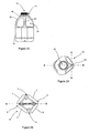
- the corner regions 3, 4 may be rounded (e.g. as in Figure 5 ) or truncated (e.g. as in Figure 11 ), thereby producing a footprint with up to four additional sides (e.g.
- the degree of curvature or truncation at the corner regions away from the longitudinal axis will preferably differs from the degree of curvature or truncation at the corner regions along the longitudinal axis, e.g. so as to be more curved/rounded (than angular) or truncated away from longitudinal axis, as shown in the illustrated embodiments.
- the footprint has a centre point, wherein the maximum radial extent of the footprint from the centre point is greatest at the point at which the corner regions intersect the longitudinal axis BB (i.e. at the corner regions 3) and wherein the radial extent at the other two corner regions 4 is less than the maximum radial extent of the footprint.
- the radial extent of the footprint at no point away from the axis BB is the radial extent of the footprint greater than or equal to the radial extent on the axis BB at the corner regions 3.
- the footprint of the body when viewed from beneath, is rotationally symmetrical about said longitudinal axis BB.
- the integral handle 22 is arranged at a corner 3 of the container and extends in line with the longitudinal axis BB of the footprint.
- the integral handle is also arranged to extend in a direction which is substantially 45 degrees to the four major sides 1, 2 of the footprint.
- Each of the embodiments includes the non-planar neck intersection described with reference to Figures 26 to 28 .
- a planar neck intersection may be preferred, e. g. if the necessary topload force test requirement can be fulfilled.
- the body portion 14 defines a relief region on either side of the handle aperture 24 into or through which the user's fingers will extend when picking up the container 10 using the handle 22.
- the geometry of the containers in accordance with the preferred embodiments of the invention illustrated in Figures 1 to 24 means that the size of the relief region on one side of the longitudinal axis BB is greater than the size of the relief region on the other side of the longitudinal axis BB. This has been found to provide a physical advantage when holding the container by the handle or when the container is presented for pick up by a user, e.g. from cold storage in a conventional domestic refrigerator (depending on the direction of opening of the refrigerator door or the natural dexterity of the user).
- the containers described herein are preferably formed by blow moulding.
- the mould tool is configured such that the longitudinal axis of the handle and longitudinal axis of the body are in line with one another along a centre split line of the tool (such that the handle is arranged at one corner of the body).
- the mould tool is configured so that the mould split line is arranged corner to corner with respect to the body of the container to be produced, with the middle region of the body extending in the direction of opening of the tool (perpendicular to the split line) by a more limited extent than along the split line.
Landscapes
- Engineering & Computer Science (AREA)
- Mechanical Engineering (AREA)
- Ceramic Engineering (AREA)
- Containers Having Bodies Formed In One Piece (AREA)
- Moulds For Moulding Plastics Or The Like (AREA)
- Blow-Moulding Or Thermoforming Of Plastics Or The Like (AREA)
- Details Of Rigid Or Semi-Rigid Containers (AREA)
Claims (12)
- Récipient en plastique moulé par soufflage (10) destiné à contenir un liquide (comme du lait), le récipient (10) comportant un corps (12) avec un axe central destiné à être généralement vertical pendant un stockage, dans lequel le corps (12) a une empreinte avec un axe transversal s'étendant dans une première direction et un axe longitudinal (BB) s'étendant dans une deuxième direction qui est perpendiculaire à ladite première direction, et le point d'intersection de l'axe central, l'axe transversal et l'axe longitudinal (BB) définit un point central de l'empreinte, l'empreinte comportant quatre côtés majeurs (1, 2) et quatre régions de coin majeures (3, 4), chaque région de coin (3, 4) étant agencée entre deux côtés respectifs desdits côtés majeurs (1, 2), dans lequel deux premières régions desdites régions de coin majeures (3) sont agencées au moins généralement à l'opposé l'une de l'autre le long de l'axe longitudinal,
caractérisé en ce que l'étendue radiale maximale de l'empreinte à partir du point central est la plus grande là où l'empreinte est en intersection avec l'axe longitudinal (BB), ce qui correspond à l'emplacement de deux desdites régions de coin (3), et l'étendue radiale à partir du point central aux deux autres desdites quatre régions de coin (4) est inférieure à l'étendue radiale maximale de l'empreinte et deux deuxièmes régions desdites régions de coin majeures (4) sont agencées asymétriquement par rapport au dit axe longitudinal (BB). - Récipient (10) selon la revendication 1, dans lequel le récipient (10) est du type ayant une poignée intégrale (22) destinée à être généralement verticale pendant le stockage et définissant un oeil de poignée (24) avec un axe d'ouverture (AA) s'étendant dans la première direction à travers le corps (12).
- Récipient (10) selon la revendication 2, dans lequel ledit oeil de poignée (24) a une hauteur supérieure à sa largeur.
- Récipient (10) selon la revendication 2 ou 3, dans lequel le corps (12) définit une région de relief de chaque côté de l'oeil de poignée, et la taille de la région de relief sur un côté de l'axe longitudinal (BB) est supérieure à la taille de la région de relief sur l'autre côté de l'axe longitudinal (BB).
- Récipient (10) selon l'une quelconque des revendications 1 à 4, dans lequel l'empreinte est de configuration généralement rectangulaire, les quatre côtés majeurs (1, 2) comprenant deux paires de côtés généralement parallèles, la première desdites deux paires (1) étant agencée perpendiculairement à la deuxième desdites deux paires (2), et les côtés de ladite première paire (1) étant plus longs que les côtés de ladite deuxième paire (2).
- Récipient (10) selon l'une quelconque des revendications 1 à 5, dans lequel l'empreinte a un axe transversal perpendiculaire à l'axe longitudinal (BB) et agencé au milieu de l'axe longitudinal (BB), et les deux deuxièmes régions desdites régions de coin (4) sont décalées par rapport au dit axe transversal.
- Récipient (10) selon l'une quelconque des revendications 1 à 6, dans lequel l'empreinte, en vue par-dessous, est symétrique de manière rotationnelle par rapport au dit axe longitudinal (BB).
- Récipient (10) selon l'une quelconque des revendications précédentes, dans lequel lesdites régions de coin (3, 4) sont arrondies ou coniques au lieu de définir une région de coin rectangulaire saillant.
- Récipient (10) selon la revendication 6, dans lequel le degré de courbure ou de troncation des régions de coin (4) à l'écart de l'axe longitudinal (BB) diffère du degré de courbure ou de troncation des régions de coin (3) le long de l'axe longitudinal de manière à être davantage incurvées, arrondies ou coniques à l'écart de l'axe longitudinal (BB).
- Récipient (10) selon la revendication 2, dans lequel le corps (12) définit une chambre pour contenir un liquide, la chambre s'étendant dans et/ou à travers la poignée intégrale (22), et dans lequel le récipient comprend un goulot ayant un passage ouvert à travers celui-ci pour laisser passer un liquide à destination/en provenance de la chambre, et dans lequel le passage ouvert est situé centralement par rapport à l'empreinte du corps (12).
- Procédé de production d'un récipient en plastique (10), le procédé comprenant l'étape de la fourniture d'un outil de moulage configuré pour produire un récipient du type comportant un corps (12) ayant une empreinte avec un axe transversal s'étendant dans une première direction et un axe longitudinal (BB) s'étendant dans une deuxième direction qui est perpendiculaire à ladite première direction, dans lequel l'empreinte définit quatre côtés majeurs (1, 2) et quatre régions de coin majeures (3, 4), chaque région de coin étant agencée entre deux côtés respectifs desdits côtés majeurs (1, 2), et l'empreinte comporte un point central à travers lequel s'étendent l'axe longitudinal et l'axe transversal, caractérisé en ce que l'étendue radiale maximale de l'empreinte à partir du point central est la plus grande là où l'empreinte est en intersection avec l'axe longitudinal (BB), ce qui correspond à l'emplacement de deux desdites régions de coin, le procédé comprenant en outre l'étape du moulage par soufflage d'une matière plastique dans ledit outil de moulage, dans lequel l'outil de moulage comporte une ligne de séparation agencée d'un coin à un autre par rapport à l'empreinte souhaitée du récipient moulé par soufflage, dans lequel l'axe longitudinal de l'empreinte est aligné avec la ligne de séparation de l'outil de moulage, de sorte que l'étendue d'étirement de paraison à l'écart de la ligne de séparation d'outil de moulage soit inférieure à l'étendue d'étirement de paraison le long de la ligne de séparation.
- Outil de moulage configuré pour produire un récipient en plastique (10) selon l'une quelconque des revendications 1 à 10, ou configuré pour être utilisé dans le procédé de la revendication 11.
Priority Applications (3)
| Application Number | Priority Date | Filing Date | Title |
|---|---|---|---|
| SI201030751T SI2493770T1 (sl) | 2009-10-26 | 2010-08-25 | Plastičen vsebnik |
| EP14173191.9A EP2808264A1 (fr) | 2009-10-26 | 2010-08-25 | Récipient en plastique |
| PL10757460T PL2493770T3 (pl) | 2009-10-26 | 2010-08-25 | Pojemnik z tworzywa sztucznego |
Applications Claiming Priority (3)
| Application Number | Priority Date | Filing Date | Title |
|---|---|---|---|
| GBGB0918744.4A GB0918744D0 (en) | 2009-10-26 | 2009-10-26 | Plastic container |
| GBGB1011029.4A GB201011029D0 (en) | 2009-10-26 | 2010-07-01 | Plastic container |
| PCT/GB2010/051412 WO2011051694A1 (fr) | 2009-10-26 | 2010-08-25 | Récipient en plastique |
Related Child Applications (1)
| Application Number | Title | Priority Date | Filing Date |
|---|---|---|---|
| EP14173191.9A Division EP2808264A1 (fr) | 2009-10-26 | 2010-08-25 | Récipient en plastique |
Publications (2)
| Publication Number | Publication Date |
|---|---|
| EP2493770A1 EP2493770A1 (fr) | 2012-09-05 |
| EP2493770B1 true EP2493770B1 (fr) | 2014-07-09 |
Family
ID=41426715
Family Applications (2)
| Application Number | Title | Priority Date | Filing Date |
|---|---|---|---|
| EP14173191.9A Withdrawn EP2808264A1 (fr) | 2009-10-26 | 2010-08-25 | Récipient en plastique |
| EP10757460.0A Not-in-force EP2493770B1 (fr) | 2009-10-26 | 2010-08-25 | Récipient en plastique |
Family Applications Before (1)
| Application Number | Title | Priority Date | Filing Date |
|---|---|---|---|
| EP14173191.9A Withdrawn EP2808264A1 (fr) | 2009-10-26 | 2010-08-25 | Récipient en plastique |
Country Status (17)
| Country | Link |
|---|---|
| US (1) | US8517195B2 (fr) |
| EP (2) | EP2808264A1 (fr) |
| JP (1) | JP2013508230A (fr) |
| CN (1) | CN102666291B (fr) |
| AU (1) | AU2010311188B2 (fr) |
| BR (1) | BR112012009869A2 (fr) |
| CA (1) | CA2778087A1 (fr) |
| DK (1) | DK2493770T3 (fr) |
| ES (1) | ES2507146T3 (fr) |
| GB (3) | GB0918744D0 (fr) |
| MX (1) | MX2012004865A (fr) |
| NZ (1) | NZ599450A (fr) |
| PL (1) | PL2493770T3 (fr) |
| PT (1) | PT2493770E (fr) |
| SI (1) | SI2493770T1 (fr) |
| WO (1) | WO2011051694A1 (fr) |
| ZA (1) | ZA201203062B (fr) |
Families Citing this family (7)
| Publication number | Priority date | Publication date | Assignee | Title |
|---|---|---|---|---|
| WO2011131920A1 (fr) * | 2010-04-20 | 2011-10-27 | Nampak Plastics Europe Limited | Contenant en plastique |
| US10096049B2 (en) | 2010-04-30 | 2018-10-09 | H-Source, Inc. | Perishable medical product management systems, perishable medical product management methods, and perishable medical product resale methods |
| US8668101B2 (en) | 2011-03-23 | 2014-03-11 | Mid-America Machining, Inc. | Method and apparatus for making a light weight container |
| JP5999545B2 (ja) * | 2012-03-30 | 2016-09-28 | 株式会社吉野工業所 | ブロー容器 |
| CN103708072A (zh) * | 2014-01-24 | 2014-04-09 | 上海福将塑胶工业集团有限公司 | 复合式散装容器的塑料内容器 |
| USD818359S1 (en) * | 2016-04-08 | 2018-05-22 | Henkel IP & Holding GmbH | Container |
| EP4169695A1 (fr) * | 2020-09-17 | 2023-04-26 | Guangzhou Tech-Long Packaging Machinery Co., Ltd | Moule de moulage par soufflage, machine de soufflage de bouteille et bouteille en plastique |
Family Cites Families (30)
| Publication number | Priority date | Publication date | Assignee | Title |
|---|---|---|---|---|
| US2641374A (en) * | 1949-10-29 | 1953-06-09 | Yee Sing Chun | Container |
| US3214052A (en) | 1964-08-10 | 1965-10-26 | Climalene Company | Bottle construction |
| US3708082A (en) * | 1971-03-29 | 1973-01-02 | Hoover Ball & Bearing Co | Plastic container |
| DE2249759C2 (de) * | 1972-10-11 | 1982-11-18 | Daimler-Benz Ag, 7000 Stuttgart | Haltesystem für die Insassen eines Kraftfahrzeuges |
| US3892829A (en) * | 1973-10-03 | 1975-07-01 | Owens Illinois Inc | Method of making blown plastic articles |
| US4016995A (en) * | 1975-12-08 | 1977-04-12 | Plastipak Packaging | Liquid container |
| US5112561A (en) * | 1990-10-19 | 1992-05-12 | Edward S. Robbins, III | Blow-molding methods for fabricating hollow articles from an open-ended tubular body of thermoplastic material |
| JPH06247448A (ja) * | 1993-02-19 | 1994-09-06 | Fuji Photo Film Co Ltd | 流体用容器 |
| JP3531285B2 (ja) * | 1995-05-26 | 2004-05-24 | 凸版印刷株式会社 | プラスチックボトル |
| JP3493811B2 (ja) * | 1995-06-05 | 2004-02-03 | 凸版印刷株式会社 | プラスチックボトル |
| USD391854S (en) * | 1997-04-11 | 1998-03-10 | Hoover Universal, Inc. | Beverage container |
| US6068161A (en) * | 1997-07-01 | 2000-05-30 | Creative Edge Design Group, Ltd. | Stackable, thin-walled containers having a structural load distributing feature permitting caseless shipping |
| US5927533A (en) * | 1997-07-11 | 1999-07-27 | Pepsico, Inc. | Pressured thermoplastic beverage containing bottle with finger gripping formations |
| WO1999022994A1 (fr) * | 1997-10-30 | 1999-05-14 | Uniloy Milacron Inc. | Pot a lait |
| KR100699122B1 (ko) * | 1998-03-20 | 2007-03-21 | 가부시키가이샤 요시노 고교쇼 | 손잡이 부착 플라스틱 보틀 |
| USD417621S (en) * | 1998-04-02 | 1999-12-14 | Owens-Brockway Plastic Products Inc. | Bottle |
| US6059153A (en) * | 1998-10-09 | 2000-05-09 | Kraft Foods, Inc. | Container for pourable food products |
| USD419423S (en) * | 1998-12-29 | 2000-01-25 | Ayrest Robert B | Door catch |
| US6889858B2 (en) * | 2000-11-03 | 2005-05-10 | Portola Packaging, Inc. | Multiple label container |
| US6527133B1 (en) * | 2000-11-03 | 2003-03-04 | Portola Packaging, Inc. | Multiple label liquid container |
| US7000793B2 (en) * | 2003-02-24 | 2006-02-21 | Graham Packaging Co., L.P. | Hot-fill container base structure |
| CN1886304A (zh) * | 2003-12-01 | 2006-12-27 | 宝洁公司 | 具有一个或多个隔室及提手的容器 |
| WO2006022817A2 (fr) * | 2004-08-19 | 2006-03-02 | Plastipak Packaging, Inc. | Recipient en plastique |
| US7699171B2 (en) * | 2004-11-20 | 2010-04-20 | Consolidated Container Company Lp | Stackable containers and methods of manufacturing, stacking, and shipping the same |
| US20060261030A1 (en) * | 2004-11-28 | 2006-11-23 | Consolidated Container Company Lp | Containers with dual orientation dispensing feature |
| US8017065B2 (en) * | 2006-04-07 | 2011-09-13 | Graham Packaging Company L.P. | System and method for forming a container having a grip region |
| JP4887665B2 (ja) * | 2005-05-30 | 2012-02-29 | 東洋製罐株式会社 | 把手付耐熱容器 |
| US20070221606A1 (en) * | 2006-03-23 | 2007-09-27 | Eiten Carl T | Liquid Container |
| US7874442B2 (en) * | 2006-10-06 | 2011-01-25 | Amcor Limited | Hot-fill plastic container with ribs and grip |
| US8047392B2 (en) * | 2007-03-05 | 2011-11-01 | Dean Intellectual Property Services Ii, Inc. | Stackable liquid container |
-
2009
- 2009-10-26 GB GBGB0918744.4A patent/GB0918744D0/en not_active Ceased
-
2010
- 2010-07-01 GB GBGB1011029.4A patent/GB201011029D0/en not_active Ceased
- 2010-08-25 CA CA2778087A patent/CA2778087A1/fr not_active Abandoned
- 2010-08-25 GB GB1014197A patent/GB2470316B/en not_active Expired - Fee Related
- 2010-08-25 NZ NZ599450A patent/NZ599450A/xx unknown
- 2010-08-25 AU AU2010311188A patent/AU2010311188B2/en active Active
- 2010-08-25 SI SI201030751T patent/SI2493770T1/sl unknown
- 2010-08-25 EP EP14173191.9A patent/EP2808264A1/fr not_active Withdrawn
- 2010-08-25 US US12/993,769 patent/US8517195B2/en not_active Expired - Fee Related
- 2010-08-25 DK DK10757460.0T patent/DK2493770T3/da active
- 2010-08-25 CN CN201080053412.1A patent/CN102666291B/zh not_active Expired - Fee Related
- 2010-08-25 MX MX2012004865A patent/MX2012004865A/es active IP Right Grant
- 2010-08-25 EP EP10757460.0A patent/EP2493770B1/fr not_active Not-in-force
- 2010-08-25 PL PL10757460T patent/PL2493770T3/pl unknown
- 2010-08-25 BR BR112012009869A patent/BR112012009869A2/pt not_active IP Right Cessation
- 2010-08-25 PT PT107574600T patent/PT2493770E/pt unknown
- 2010-08-25 ES ES10757460.0T patent/ES2507146T3/es active Active
- 2010-08-25 WO PCT/GB2010/051412 patent/WO2011051694A1/fr active Application Filing
- 2010-09-22 JP JP2012534771A patent/JP2013508230A/ja not_active Withdrawn
-
2012
- 2012-04-25 ZA ZA2012/03062A patent/ZA201203062B/en unknown
Also Published As
| Publication number | Publication date |
|---|---|
| GB2470316B (en) | 2011-04-13 |
| CN102666291A (zh) | 2012-09-12 |
| PL2493770T3 (pl) | 2014-12-31 |
| GB201014197D0 (en) | 2010-10-06 |
| CN102666291B (zh) | 2014-08-06 |
| BR112012009869A2 (pt) | 2016-09-27 |
| ES2507146T3 (es) | 2014-10-14 |
| GB0918744D0 (en) | 2009-12-09 |
| WO2011051694A1 (fr) | 2011-05-05 |
| GB2470316A (en) | 2010-11-17 |
| JP2013508230A (ja) | 2013-03-07 |
| PT2493770E (pt) | 2014-09-24 |
| EP2808264A1 (fr) | 2014-12-03 |
| SI2493770T1 (sl) | 2014-11-28 |
| NZ599450A (en) | 2013-05-31 |
| AU2010311188A1 (en) | 2012-05-17 |
| EP2493770A1 (fr) | 2012-09-05 |
| GB201011029D0 (en) | 2010-08-18 |
| MX2012004865A (es) | 2012-06-08 |
| US8517195B2 (en) | 2013-08-27 |
| CA2778087A1 (fr) | 2011-05-05 |
| US20110215104A1 (en) | 2011-09-08 |
| AU2010311188B2 (en) | 2013-07-25 |
| ZA201203062B (en) | 2012-12-27 |
| DK2493770T3 (da) | 2014-10-13 |
Similar Documents
| Publication | Publication Date | Title |
|---|---|---|
| EP2540633B1 (fr) | Récipient en plastique | |
| EP2493770B1 (fr) | Récipient en plastique | |
| US20130001234A1 (en) | Plastics Container | |
| AU2014200122B2 (en) | Plastics container | |
| GB2464857A (en) | A blow moulded plastics container for storing liquid |
Legal Events
| Date | Code | Title | Description |
|---|---|---|---|
| PUAI | Public reference made under article 153(3) epc to a published international application that has entered the european phase |
Free format text: ORIGINAL CODE: 0009012 |
|
| 17P | Request for examination filed |
Effective date: 20120517 |
|
| AK | Designated contracting states |
Kind code of ref document: A1 Designated state(s): AL AT BE BG CH CY CZ DE DK EE ES FI FR GB GR HR HU IE IS IT LI LT LU LV MC MK MT NL NO PL PT RO SE SI SK SM TR |
|
| DAX | Request for extension of the european patent (deleted) | ||
| 17Q | First examination report despatched |
Effective date: 20130416 |
|
| GRAP | Despatch of communication of intention to grant a patent |
Free format text: ORIGINAL CODE: EPIDOSNIGR1 |
|
| INTG | Intention to grant announced |
Effective date: 20140129 |
|
| GRAS | Grant fee paid |
Free format text: ORIGINAL CODE: EPIDOSNIGR3 |
|
| GRAA | (expected) grant |
Free format text: ORIGINAL CODE: 0009210 |
|
| AK | Designated contracting states |
Kind code of ref document: B1 Designated state(s): AL AT BE BG CH CY CZ DE DK EE ES FI FR GB GR HR HU IE IS IT LI LT LU LV MC MK MT NL NO PL PT RO SE SI SK SM TR |
|
| REG | Reference to a national code |
Ref country code: GB Ref legal event code: FG4D |
|
| REG | Reference to a national code |
Ref country code: CH Ref legal event code: EP Ref country code: AT Ref legal event code: REF Ref document number: 676481 Country of ref document: AT Kind code of ref document: T Effective date: 20140715 |
|
| REG | Reference to a national code |
Ref country code: IE Ref legal event code: FG4D |
|
| REG | Reference to a national code |
Ref country code: DE Ref legal event code: R096 Ref document number: 602010017376 Country of ref document: DE Effective date: 20140814 |
|
| REG | Reference to a national code |
Ref country code: PT Ref legal event code: SC4A Free format text: AVAILABILITY OF NATIONAL TRANSLATION Effective date: 20140918 |
|
| REG | Reference to a national code |
Ref country code: RO Ref legal event code: EPE |
|
| REG | Reference to a national code |
Ref country code: DK Ref legal event code: T3 Effective date: 20141009 |
|
| REG | Reference to a national code |
Ref country code: ES Ref legal event code: FG2A Ref document number: 2507146 Country of ref document: ES Kind code of ref document: T3 Effective date: 20141014 |
|
| REG | Reference to a national code |
Ref country code: SE Ref legal event code: TRGR |
|
| REG | Reference to a national code |
Ref country code: NL Ref legal event code: T3 |
|
| REG | Reference to a national code |
Ref country code: LT Ref legal event code: MG4D |
|
| REG | Reference to a national code |
Ref country code: PL Ref legal event code: T3 |
|
| REG | Reference to a national code |
Ref country code: SK Ref legal event code: T3 Ref document number: E 17266 Country of ref document: SK |
|
| REG | Reference to a national code |
Ref country code: GR Ref legal event code: EP Ref document number: 20140402031 Country of ref document: GR Effective date: 20141121 |
|
| PG25 | Lapsed in a contracting state [announced via postgrant information from national office to epo] |
Ref country code: NO Free format text: LAPSE BECAUSE OF FAILURE TO SUBMIT A TRANSLATION OF THE DESCRIPTION OR TO PAY THE FEE WITHIN THE PRESCRIBED TIME-LIMIT Effective date: 20141009 Ref country code: BG Free format text: LAPSE BECAUSE OF FAILURE TO SUBMIT A TRANSLATION OF THE DESCRIPTION OR TO PAY THE FEE WITHIN THE PRESCRIBED TIME-LIMIT Effective date: 20141009 Ref country code: LT Free format text: LAPSE BECAUSE OF FAILURE TO SUBMIT A TRANSLATION OF THE DESCRIPTION OR TO PAY THE FEE WITHIN THE PRESCRIBED TIME-LIMIT Effective date: 20140709 |
|
| PGFP | Annual fee paid to national office [announced via postgrant information from national office to epo] |
Ref country code: SK Payment date: 20141031 Year of fee payment: 5 |
|
| PG25 | Lapsed in a contracting state [announced via postgrant information from national office to epo] |
Ref country code: HR Free format text: LAPSE BECAUSE OF FAILURE TO SUBMIT A TRANSLATION OF THE DESCRIPTION OR TO PAY THE FEE WITHIN THE PRESCRIBED TIME-LIMIT Effective date: 20140709 Ref country code: LV Free format text: LAPSE BECAUSE OF FAILURE TO SUBMIT A TRANSLATION OF THE DESCRIPTION OR TO PAY THE FEE WITHIN THE PRESCRIBED TIME-LIMIT Effective date: 20140709 |
|
| PGFP | Annual fee paid to national office [announced via postgrant information from national office to epo] |
Ref country code: SI Payment date: 20141028 Year of fee payment: 5 |
|
| REG | Reference to a national code |
Ref country code: HU Ref legal event code: AG4A Ref document number: E021955 Country of ref document: HU |
|
| REG | Reference to a national code |
Ref country code: CH Ref legal event code: PL |
|
| REG | Reference to a national code |
Ref country code: DE Ref legal event code: R097 Ref document number: 602010017376 Country of ref document: DE |
|
| PG25 | Lapsed in a contracting state [announced via postgrant information from national office to epo] |
Ref country code: LI Free format text: LAPSE BECAUSE OF NON-PAYMENT OF DUE FEES Effective date: 20140831 Ref country code: CH Free format text: LAPSE BECAUSE OF NON-PAYMENT OF DUE FEES Effective date: 20140831 Ref country code: MC Free format text: LAPSE BECAUSE OF FAILURE TO SUBMIT A TRANSLATION OF THE DESCRIPTION OR TO PAY THE FEE WITHIN THE PRESCRIBED TIME-LIMIT Effective date: 20140709 Ref country code: EE Free format text: LAPSE BECAUSE OF FAILURE TO SUBMIT A TRANSLATION OF THE DESCRIPTION OR TO PAY THE FEE WITHIN THE PRESCRIBED TIME-LIMIT Effective date: 20140709 |
|
| PLBE | No opposition filed within time limit |
Free format text: ORIGINAL CODE: 0009261 |
|
| STAA | Information on the status of an ep patent application or granted ep patent |
Free format text: STATUS: NO OPPOSITION FILED WITHIN TIME LIMIT |
|
| PGFP | Annual fee paid to national office [announced via postgrant information from national office to epo] |
Ref country code: CY Payment date: 20141024 Year of fee payment: 5 |
|
| 26N | No opposition filed |
Effective date: 20150410 |
|
| REG | Reference to a national code |
Ref country code: FR Ref legal event code: PLFP Year of fee payment: 6 |
|
| PGFP | Annual fee paid to national office [announced via postgrant information from national office to epo] |
Ref country code: DK Payment date: 20151030 Year of fee payment: 6 |
|
| PGFP | Annual fee paid to national office [announced via postgrant information from national office to epo] |
Ref country code: FI Payment date: 20151111 Year of fee payment: 6 Ref country code: IT Payment date: 20151030 Year of fee payment: 6 Ref country code: TR Payment date: 20151113 Year of fee payment: 6 Ref country code: GR Payment date: 20151112 Year of fee payment: 6 Ref country code: DE Payment date: 20151030 Year of fee payment: 6 |
|
| PGFP | Annual fee paid to national office [announced via postgrant information from national office to epo] |
Ref country code: BE Payment date: 20151030 Year of fee payment: 6 Ref country code: IS Payment date: 20151110 Year of fee payment: 6 Ref country code: CZ Payment date: 20151112 Year of fee payment: 6 Ref country code: ES Payment date: 20151027 Year of fee payment: 6 Ref country code: SE Payment date: 20151030 Year of fee payment: 6 Ref country code: AT Payment date: 20151102 Year of fee payment: 6 Ref country code: PT Payment date: 20151110 Year of fee payment: 6 Ref country code: FR Payment date: 20151030 Year of fee payment: 6 Ref country code: HU Payment date: 20151118 Year of fee payment: 6 Ref country code: PL Payment date: 20151113 Year of fee payment: 6 Ref country code: RO Payment date: 20151111 Year of fee payment: 6 |
|
| PG25 | Lapsed in a contracting state [announced via postgrant information from national office to epo] |
Ref country code: CY Free format text: LAPSE BECAUSE OF NON-PAYMENT OF DUE FEES Effective date: 20150825 Ref country code: SM Free format text: LAPSE BECAUSE OF FAILURE TO SUBMIT A TRANSLATION OF THE DESCRIPTION OR TO PAY THE FEE WITHIN THE PRESCRIBED TIME-LIMIT Effective date: 20140709 Ref country code: SK Free format text: LAPSE BECAUSE OF NON-PAYMENT OF DUE FEES Effective date: 20150825 |
|
| REG | Reference to a national code |
Ref country code: SK Ref legal event code: MM4A Ref document number: E 17266 Country of ref document: SK Effective date: 20150825 |
|
| PG25 | Lapsed in a contracting state [announced via postgrant information from national office to epo] |
Ref country code: SI Free format text: LAPSE BECAUSE OF NON-PAYMENT OF DUE FEES Effective date: 20150826 |
|
| PGFP | Annual fee paid to national office [announced via postgrant information from national office to epo] |
Ref country code: NL Payment date: 20160128 Year of fee payment: 6 |
|
| REG | Reference to a national code |
Ref country code: SI Ref legal event code: KO00 Effective date: 20160405 |
|
| PG25 | Lapsed in a contracting state [announced via postgrant information from national office to epo] |
Ref country code: MT Free format text: LAPSE BECAUSE OF FAILURE TO SUBMIT A TRANSLATION OF THE DESCRIPTION OR TO PAY THE FEE WITHIN THE PRESCRIBED TIME-LIMIT Effective date: 20140709 |
|
| PG25 | Lapsed in a contracting state [announced via postgrant information from national office to epo] |
Ref country code: LU Free format text: LAPSE BECAUSE OF NON-PAYMENT OF DUE FEES Effective date: 20140825 |
|
| PG25 | Lapsed in a contracting state [announced via postgrant information from national office to epo] |
Ref country code: BE Free format text: LAPSE BECAUSE OF NON-PAYMENT OF DUE FEES Effective date: 20160831 |
|
| REG | Reference to a national code |
Ref country code: DE Ref legal event code: R119 Ref document number: 602010017376 Country of ref document: DE |
|
| REG | Reference to a national code |
Ref country code: DK Ref legal event code: EBP Effective date: 20160831 |
|
| REG | Reference to a national code |
Ref country code: SE Ref legal event code: EUG |
|
| REG | Reference to a national code |
Ref country code: NL Ref legal event code: MM Effective date: 20160901 |
|
| REG | Reference to a national code |
Ref country code: AT Ref legal event code: MM01 Ref document number: 676481 Country of ref document: AT Kind code of ref document: T Effective date: 20160825 |
|
| PG25 | Lapsed in a contracting state [announced via postgrant information from national office to epo] |
Ref country code: RO Free format text: LAPSE BECAUSE OF NON-PAYMENT OF DUE FEES Effective date: 20160825 Ref country code: HU Free format text: LAPSE BECAUSE OF NON-PAYMENT OF DUE FEES Effective date: 20160826 Ref country code: SE Free format text: LAPSE BECAUSE OF NON-PAYMENT OF DUE FEES Effective date: 20160826 Ref country code: GR Free format text: LAPSE BECAUSE OF NON-PAYMENT OF DUE FEES Effective date: 20170309 Ref country code: FI Free format text: LAPSE BECAUSE OF NON-PAYMENT OF DUE FEES Effective date: 20160825 |
|
| REG | Reference to a national code |
Ref country code: GR Ref legal event code: ML Ref document number: 20140402031 Country of ref document: GR Effective date: 20170309 |
|
| REG | Reference to a national code |
Ref country code: FR Ref legal event code: ST Effective date: 20170428 |
|
| PG25 | Lapsed in a contracting state [announced via postgrant information from national office to epo] |
Ref country code: CZ Free format text: LAPSE BECAUSE OF NON-PAYMENT OF DUE FEES Effective date: 20160825 Ref country code: PT Free format text: LAPSE BECAUSE OF NON-PAYMENT OF DUE FEES Effective date: 20170227 Ref country code: IS Free format text: LAPSE BECAUSE OF FAILURE TO SUBMIT A TRANSLATION OF THE DESCRIPTION OR TO PAY THE FEE WITHIN THE PRESCRIBED TIME-LIMIT Effective date: 20170301 Ref country code: AT Free format text: LAPSE BECAUSE OF NON-PAYMENT OF DUE FEES Effective date: 20160825 |
|
| PG25 | Lapsed in a contracting state [announced via postgrant information from national office to epo] |
Ref country code: NL Free format text: LAPSE BECAUSE OF NON-PAYMENT OF DUE FEES Effective date: 20160901 |
|
| PG25 | Lapsed in a contracting state [announced via postgrant information from national office to epo] |
Ref country code: DE Free format text: LAPSE BECAUSE OF NON-PAYMENT OF DUE FEES Effective date: 20170301 Ref country code: FR Free format text: LAPSE BECAUSE OF NON-PAYMENT OF DUE FEES Effective date: 20160831 Ref country code: DK Free format text: LAPSE BECAUSE OF NON-PAYMENT OF DUE FEES Effective date: 20160831 |
|
| PG25 | Lapsed in a contracting state [announced via postgrant information from national office to epo] |
Ref country code: IT Free format text: LAPSE BECAUSE OF NON-PAYMENT OF DUE FEES Effective date: 20160825 |
|
| PG25 | Lapsed in a contracting state [announced via postgrant information from national office to epo] |
Ref country code: PL Free format text: LAPSE BECAUSE OF NON-PAYMENT OF DUE FEES Effective date: 20160825 |
|
| PG25 | Lapsed in a contracting state [announced via postgrant information from national office to epo] |
Ref country code: ES Free format text: LAPSE BECAUSE OF NON-PAYMENT OF DUE FEES Effective date: 20160826 |
|
| PG25 | Lapsed in a contracting state [announced via postgrant information from national office to epo] |
Ref country code: MK Free format text: LAPSE BECAUSE OF FAILURE TO SUBMIT A TRANSLATION OF THE DESCRIPTION OR TO PAY THE FEE WITHIN THE PRESCRIBED TIME-LIMIT Effective date: 20140709 |
|
| PG25 | Lapsed in a contracting state [announced via postgrant information from national office to epo] |
Ref country code: AL Free format text: LAPSE BECAUSE OF FAILURE TO SUBMIT A TRANSLATION OF THE DESCRIPTION OR TO PAY THE FEE WITHIN THE PRESCRIBED TIME-LIMIT Effective date: 20140709 |
|
| REG | Reference to a national code |
Ref country code: ES Ref legal event code: FD2A Effective date: 20181116 |
|
| PGFP | Annual fee paid to national office [announced via postgrant information from national office to epo] |
Ref country code: IE Payment date: 20200811 Year of fee payment: 11 Ref country code: GB Payment date: 20200813 Year of fee payment: 11 |
|
| GBPC | Gb: european patent ceased through non-payment of renewal fee |
Effective date: 20210825 |
|
| PG25 | Lapsed in a contracting state [announced via postgrant information from national office to epo] |
Ref country code: TR Free format text: LAPSE BECAUSE OF NON-PAYMENT OF DUE FEES Effective date: 20160825 |
|
| PG25 | Lapsed in a contracting state [announced via postgrant information from national office to epo] |
Ref country code: IE Free format text: LAPSE BECAUSE OF NON-PAYMENT OF DUE FEES Effective date: 20210825 Ref country code: GB Free format text: LAPSE BECAUSE OF NON-PAYMENT OF DUE FEES Effective date: 20210825 |