EP2493698B1 - Security devices and methods of manufacturing them - Google Patents
Security devices and methods of manufacturing them Download PDFInfo
- Publication number
- EP2493698B1 EP2493698B1 EP10775854.2A EP10775854A EP2493698B1 EP 2493698 B1 EP2493698 B1 EP 2493698B1 EP 10775854 A EP10775854 A EP 10775854A EP 2493698 B1 EP2493698 B1 EP 2493698B1
- Authority
- EP
- European Patent Office
- Prior art keywords
- image
- strips
- lenticular
- colour
- pair
- Prior art date
- Legal status (The legal status is an assumption and is not a legal conclusion. Google has not performed a legal analysis and makes no representation as to the accuracy of the status listed.)
- Active
Links
Images


Classifications
-
- B—PERFORMING OPERATIONS; TRANSPORTING
- B42—BOOKBINDING; ALBUMS; FILES; SPECIAL PRINTED MATTER
- B42D—BOOKS; BOOK COVERS; LOOSE LEAVES; PRINTED MATTER CHARACTERISED BY IDENTIFICATION OR SECURITY FEATURES; PRINTED MATTER OF SPECIAL FORMAT OR STYLE NOT OTHERWISE PROVIDED FOR; DEVICES FOR USE THEREWITH AND NOT OTHERWISE PROVIDED FOR; MOVABLE-STRIP WRITING OR READING APPARATUS
- B42D25/00—Information-bearing cards or sheet-like structures characterised by identification or security features; Manufacture thereof
- B42D25/20—Information-bearing cards or sheet-like structures characterised by identification or security features; Manufacture thereof characterised by a particular use or purpose
- B42D25/21—Information-bearing cards or sheet-like structures characterised by identification or security features; Manufacture thereof characterised by a particular use or purpose for multiple purposes
-
- B—PERFORMING OPERATIONS; TRANSPORTING
- B42—BOOKBINDING; ALBUMS; FILES; SPECIAL PRINTED MATTER
- B42D—BOOKS; BOOK COVERS; LOOSE LEAVES; PRINTED MATTER CHARACTERISED BY IDENTIFICATION OR SECURITY FEATURES; PRINTED MATTER OF SPECIAL FORMAT OR STYLE NOT OTHERWISE PROVIDED FOR; DEVICES FOR USE THEREWITH AND NOT OTHERWISE PROVIDED FOR; MOVABLE-STRIP WRITING OR READING APPARATUS
- B42D25/00—Information-bearing cards or sheet-like structures characterised by identification or security features; Manufacture thereof
- B42D25/20—Information-bearing cards or sheet-like structures characterised by identification or security features; Manufacture thereof characterised by a particular use or purpose
- B42D25/29—Securities; Bank notes
-
- B—PERFORMING OPERATIONS; TRANSPORTING
- B42—BOOKBINDING; ALBUMS; FILES; SPECIAL PRINTED MATTER
- B42D—BOOKS; BOOK COVERS; LOOSE LEAVES; PRINTED MATTER CHARACTERISED BY IDENTIFICATION OR SECURITY FEATURES; PRINTED MATTER OF SPECIAL FORMAT OR STYLE NOT OTHERWISE PROVIDED FOR; DEVICES FOR USE THEREWITH AND NOT OTHERWISE PROVIDED FOR; MOVABLE-STRIP WRITING OR READING APPARATUS
- B42D25/00—Information-bearing cards or sheet-like structures characterised by identification or security features; Manufacture thereof
- B42D25/30—Identification or security features, e.g. for preventing forgery
- B42D25/324—Reliefs
-
- B—PERFORMING OPERATIONS; TRANSPORTING
- B42—BOOKBINDING; ALBUMS; FILES; SPECIAL PRINTED MATTER
- B42D—BOOKS; BOOK COVERS; LOOSE LEAVES; PRINTED MATTER CHARACTERISED BY IDENTIFICATION OR SECURITY FEATURES; PRINTED MATTER OF SPECIAL FORMAT OR STYLE NOT OTHERWISE PROVIDED FOR; DEVICES FOR USE THEREWITH AND NOT OTHERWISE PROVIDED FOR; MOVABLE-STRIP WRITING OR READING APPARATUS
- B42D25/00—Information-bearing cards or sheet-like structures characterised by identification or security features; Manufacture thereof
- B42D25/30—Identification or security features, e.g. for preventing forgery
- B42D25/328—Diffraction gratings; Holograms
-
- B—PERFORMING OPERATIONS; TRANSPORTING
- B42—BOOKBINDING; ALBUMS; FILES; SPECIAL PRINTED MATTER
- B42D—BOOKS; BOOK COVERS; LOOSE LEAVES; PRINTED MATTER CHARACTERISED BY IDENTIFICATION OR SECURITY FEATURES; PRINTED MATTER OF SPECIAL FORMAT OR STYLE NOT OTHERWISE PROVIDED FOR; DEVICES FOR USE THEREWITH AND NOT OTHERWISE PROVIDED FOR; MOVABLE-STRIP WRITING OR READING APPARATUS
- B42D25/00—Information-bearing cards or sheet-like structures characterised by identification or security features; Manufacture thereof
- B42D25/30—Identification or security features, e.g. for preventing forgery
- B42D25/342—Moiré effects
-
- B—PERFORMING OPERATIONS; TRANSPORTING
- B42—BOOKBINDING; ALBUMS; FILES; SPECIAL PRINTED MATTER
- B42D—BOOKS; BOOK COVERS; LOOSE LEAVES; PRINTED MATTER CHARACTERISED BY IDENTIFICATION OR SECURITY FEATURES; PRINTED MATTER OF SPECIAL FORMAT OR STYLE NOT OTHERWISE PROVIDED FOR; DEVICES FOR USE THEREWITH AND NOT OTHERWISE PROVIDED FOR; MOVABLE-STRIP WRITING OR READING APPARATUS
- B42D25/00—Information-bearing cards or sheet-like structures characterised by identification or security features; Manufacture thereof
- B42D25/30—Identification or security features, e.g. for preventing forgery
- B42D25/351—Translucent or partly translucent parts, e.g. windows
-
- B—PERFORMING OPERATIONS; TRANSPORTING
- B42—BOOKBINDING; ALBUMS; FILES; SPECIAL PRINTED MATTER
- B42D—BOOKS; BOOK COVERS; LOOSE LEAVES; PRINTED MATTER CHARACTERISED BY IDENTIFICATION OR SECURITY FEATURES; PRINTED MATTER OF SPECIAL FORMAT OR STYLE NOT OTHERWISE PROVIDED FOR; DEVICES FOR USE THEREWITH AND NOT OTHERWISE PROVIDED FOR; MOVABLE-STRIP WRITING OR READING APPARATUS
- B42D25/00—Information-bearing cards or sheet-like structures characterised by identification or security features; Manufacture thereof
- B42D25/30—Identification or security features, e.g. for preventing forgery
- B42D25/36—Identification or security features, e.g. for preventing forgery comprising special materials
- B42D25/373—Metallic materials
-
- B—PERFORMING OPERATIONS; TRANSPORTING
- B42—BOOKBINDING; ALBUMS; FILES; SPECIAL PRINTED MATTER
- B42D—BOOKS; BOOK COVERS; LOOSE LEAVES; PRINTED MATTER CHARACTERISED BY IDENTIFICATION OR SECURITY FEATURES; PRINTED MATTER OF SPECIAL FORMAT OR STYLE NOT OTHERWISE PROVIDED FOR; DEVICES FOR USE THEREWITH AND NOT OTHERWISE PROVIDED FOR; MOVABLE-STRIP WRITING OR READING APPARATUS
- B42D25/00—Information-bearing cards or sheet-like structures characterised by identification or security features; Manufacture thereof
- B42D25/40—Manufacture
-
- G—PHYSICS
- G02—OPTICS
- G02B—OPTICAL ELEMENTS, SYSTEMS OR APPARATUS
- G02B30/00—Optical systems or apparatus for producing three-dimensional [3D] effects, e.g. stereoscopic images
- G02B30/20—Optical systems or apparatus for producing three-dimensional [3D] effects, e.g. stereoscopic images by providing first and second parallax images to an observer's left and right eyes
- G02B30/26—Optical systems or apparatus for producing three-dimensional [3D] effects, e.g. stereoscopic images by providing first and second parallax images to an observer's left and right eyes of the autostereoscopic type
- G02B30/27—Optical systems or apparatus for producing three-dimensional [3D] effects, e.g. stereoscopic images by providing first and second parallax images to an observer's left and right eyes of the autostereoscopic type involving lenticular arrays
-
- B42D2035/24—
-
- B42D2035/44—
Definitions
- the invention relates to a security device, for example for use on articles of value such as banknotes, cheques, passports, identity cards, certificates of authenticity, fiscal stamps and other documents for securing value or personal identity.
- the colourshift exhibited by a liquid crystal film is always from a colour with a long wavelength to a colour with a shorter wavelength, for example red to green, as the an angle of incidence is increased away from normal incidence.
- so called lenticular devices can be used as security devices as, for example, described in US-A-4892336 .
- the microprinting used with these lenticular devices comprises strips of different colours such that when a device, such as a thread, is viewed at different angles, different colours will be perceived.
- One of the problems with this approach is the need for a very precise register between the microlenses and microprinting.
- this need for precise register is put forward as one of the advantages of that invention in that it makes it very much more difficult to counterfeit such security devices.
- genuine devices must be relatively easy to manufacture since otherwise production costs will be prohibitive.
- US-A-4765656 also describes a security device made using a lenticular screen and in this case the microimages are formed by direct laser writing through the microlenses which are already in situ in the device. Again, this approach is not suited to mass production techniques although it does achieve exact register between the lenses and images.
- US-A-4402150 describes a lenticular device based around a latent image effect.
- the device when viewed perpendicularly or normally, the device presents a flat appearance, for example a red colour, but when viewed at other angles, a symbol is discerned against a coloured background.
- AU-B-764842 describes a lenticular device which is transparent at one angle of view but exhibits an image at another.
- US-A-5301981 describes a lenticular film having a set of opaque lines on its lower surface. The film is adhered over an image or the like to prevent it from being photocopied because at a normal angle of instance the view appears opaque whereas at an acute angle it is possible to see the underlying information.
- Other examples of conventional security devices are provided in WO-2006/110038A2 , disclosing arrays of cylindrical lenses and two component images, and US-4417784-A1 disclosing a reflective periodic structure formed as a relief pattern and lenticular array of lenses.
- WO94/27254- A1 and WO2005/052650-A2 examples of conventional security devices with arrays of semispherical lenses are provided.
- a security device has a lenticular device comprising an array of lenticular focusing elements formed by cylindrical lenses or micromirrors located over a corresponding array of pairs of image strips such that, in a first viewing direction, a first image strip from each pair is viewed by respective ones of the lenticular focusing elements and, in a second viewing direction, different from the first, a second image strip from each pair is viewed by respective ones of the lenticular focusing elements and is characterized in that one of each pair of image strips has portions defining a first image in a first colour and a second image in a second colour respectively, and the other of each pair of image strips has portions defining the first image in the second colour and the second image in the first colour respectively, whereby on tilting the device, a colour switch is observed between the first and second images.
- a method of manufacturing a security device comprises providing an array of lenticular focusing elements formed by cylindrical lenses or micromirrors on one side of a transparent substrate; and providing a corresponding array of pairs of image strips on the other side of the transparent substrate, the image strips and lenticular focusing elements defining a lenticular device such that, in a first viewing direction, a first image strip from each pair is viewed by respective ones of the lenticular focusing elements and, in a second viewing direction, different from the first, a second image strip from each pair is viewed by respective ones of the lenticular focusing elements characterized in that one of each pair of image strips has portions defining a first image in a first colour and a second image in a second colour respectively, and the other of each pair of image strips has portions defining the first image in the second colour and the second image in the first colour respectively, whereby on tilting the device, a colour switch is observed between the first and second images.
- colour extends to diffractive colours i.e. the first and second colours could have a different diffractive effect and change colour with angle but in different ways.
- the security device further comprises a second lenticular device having the same construction as the first lenticular device but in which each pair of image strips in a set are formed so that the first image strip defines portions of the first image in the second colour and the second image in the first colour respectively and the other of the pair of image strips in the set has portions defining the first image in the first colour and the second image in the second colour respectively.
- first and second lenticular devices are located adjacent one another although they could be spaced apart and, for example, separated by other optically variable devices such as lenticular devices, holograms, moire magnification devices and the like.
- a security device having a lenticular device comprising an array of lenticular focusing elements formed by cylindrical lenses or micromirrors located over a corresponding array of pairs of strips such that, in a first viewing direction, a first strip from each pair is viewed by respective ones of the lenticular focusing elements and, in a second viewing direction, different from the first, a second strip from each pair is viewed by respective ones of the lenticular focusing elements characterized in that one of each pair of strips has one or more opaque portions defining a first image and one or more transparent portions defining a second image or background respectively, and the other of each pair of strips has one or more transparent portions defining the first image and one or more opaque portions defining the second image or background respectively, whereby on tilting the device, a switch in appearance is observed between the first and second images or background.
- a method of manufacturing a security device comprising providing an array of lenticular focusing elements formed by cylindrical lenses or micromirrors on one side of a transparent substrate; and providing a corresponding array of pairs of strips on the other side of the transparent substrate, the strips and lenticular focusing elements defining a lenticular device such that, in a first viewing direction, a first strip from each pair is viewed by respective ones of the lenticular focusing elements and, in a second viewing direction, different from the first, a second strip from each pair is viewed by respective ones of the lenticular focusing elements characterized in that one of each pair of strips has one or more opaque portions defining a first image and one or more transparent portions defining a second image or background respectively, and the other of each pair of strips has one or more transparent portions defining the first image and one or more opaque portions defining the second image or background respectively, whereby on tilting the device, a switch in appearance is observed between the first
- the first image comprises one of a symbol, character, or graphic device and preferably provides information from which the secure document can be identified or authenticated while the second image may comprise a background to the first image or preferably an additional image which may be the same as the first image.
- the periodicity and therefore maximum base diameter for the lenticular focussing elements is preferably in the range 5-200 ⁇ m, more preferably 10-60 ⁇ m and even more preferably 20-40 ⁇ m.
- the f number for the lenticular focussing elements is preferably in the range 0.25-16 and more preferably 0.5-2.
- the relief structures can be formed by embossing or cast-curing. Of the two processes mentioned, cast-curing provides higher fidelity of replication.
- the image strips could simply be created by embossing/cast-curing the images as diffraction grating areas. Differing parts of the image could be differentiated by the use of differing pitches or different orientations of grating providing regions with a different diffractive colour.
- Alternative (and/or additional differentiating) image structures are anti-reflection structures such as moth-eye (see for example WO-A-2005/106601 ), zero-order diffraction structures, stepped surface relief optical structures known as Aztec structures (see for example WO-A-2005/115119 ) or simple scattering structures. For most applications, these structures could be partially or fully metallised to enhance brightness and contrast.
- each image strip formed by a relief or by printing is less than 100 microns, preferably less than 50 microns, most preferably in the range 5-25 microns.
- pairs of image strips need not be registered with the lenticular focusing elements, they should have a similar periodicity.
- the security device may comprise a metallised layer either as part of the image structures or as an additional layer. Preferably such a layer is selectively demetallised at a number of locations.
- the device may further comprise a layer of resist upon the metallised layer.
- the metallised layer and/or the layer of resist is preferably arranged as indicia.
- the device is arranged to be machine-readable. This may be achieved in a number of ways.
- at least one layer of the device may further comprise machine-readable material.
- the machine-readable material is a magnetic material, such as magnetite.
- the machine-readable material may be responsive to an external stimulus.
- this layer may be transparent.
- the security device may be used in many different applications, for example by attachment to objects of value.
- the security devices are adhered to or substantially contained within a security document.
- the security device may therefore be attached to a surface of such a document or it may be partially embedded within the document.
- the security device may take various different forms for use with security documents, these including a security thread, a security fibre, a security patch, a security strip, a security stripe or a security foil as non-limiting examples.
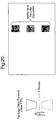
- FIG. 1 shows a cross-section through the known lenticular device which is being used to view images A-G.
- An array of cylindrical lenses 2 is arranged on a transparent substrate 4.
- Each image is segmented into a number of strips, for example 10 and under each lens 2 of the lenticular array, there is a set of image strips corresponding to a particular segmented region of images A-G.
- Three sets are shown in Figure 1 . Under the first lens the strips will each correspond to the first segment of images A-G and under the next lens the strips will each correspond to the second segment of images A-G and so forth.
- Each lens 2 is arranged to focus in the plane of the strips such that only one strip can be viewed from one viewing position through each lens 2.
- each strip of image D will be seen from straight on whereas on tilting a few degrees off-axis the strips from images C or E will be seen.
- the strips are arranged as slices of an image, i.e. the strips A are all slices from one image, similarly for B, C etc.
- the images could be related or unrelated.
- the simplest device would have two images that would flip between each other as the device is tilted.
- the images could be a series of images that are shifted laterally strip to strip generating a lenticular animation effect so that the image appears to move.
- the change from image to image could give rise to more complex animations (parts of the image change in a quasi-continuous fashion), morphing (one image transforms in small steps to another image) or zooming (an image gets larger or smaller in steps).
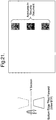
- Figure 2 shows the lenticular device in perspective view although for simplicity only two image strips per lens are shown labelled A,B respectively.
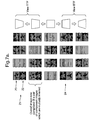
- the appearance of the device shown in Figure 2 to the observer is illustrated in Figure 3 .
- TTF top tilted forward
- view BTF bottom tilted forward
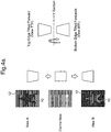
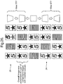
- FIGs 4A and 4B illustrate a first example of a security device according to the invention.
- an array of cylindrical lenses 2 is provided on a transparent substrate 4, as before, while pairs of image strips A,B are provided on the other side of the substrate 4 located at the focal distance of each lens.
- the strips A,B are registered with each lens 2.
- the image strips A will be seen in the region of the star through each lens 2 and when the device is viewed from the left, the image strips B will be seen in the region of the star.
- the resulting appearance of the device is shown in Figure 4A where view A corresponds to viewing the device from the right in Figure 4B and view B corresponds to viewing the device from the left in Figure 4B .
- Typical thicknesses of security devices according to the invention are 2-100 microns, more preferably 20-50microns with lens heights of 1-50 microns, more preferably 5-25microns.
- the periodicity and therefore maximum base diameter for the lenticular focussing elements is preferably in the range 5-200 ⁇ m, more preferably 10-60 ⁇ m and even more preferably 20-40 ⁇ m.
- the f number for the lenticular focussing elements is preferably in the range 0.25-16 and more preferably 0.5-2.
- the appearance of the device is of a symbol 10, in this case a star shape, seen against a background 12.
- the colours of the symbol and substrate 10,12 are chosen so that in view A, the symbol 10 has a first colour such as red and the background 12 a second colour such as blue while in view B, the colours are switched or reversed so that the star 10 has the second colour (blue) and the background 12 has the first colour (red).
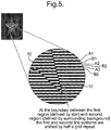
- FIG. 5 The manner in which this colour switch is achieved is shown in Figure 5 .
- part of the star symbol 10 is shown along with part of the background 12.
- Some of the image strips A,B have been labelled A1,B1;A2;B2; etc.
- Each pair of image strips A,B is registered under a corresponding lens 2 as shown in Figure 4B .
- the substrate 4 is typically a transparent polymeric material, for example bi-axial PET or polypropylene, and could be in the form of a self-supporting label which would then be adhered to an article or alternatively could be an integral part of an article.
- the device could form part of a security thread or the substrate 4 could be a substrate of the article itself such as a document of value, for example a banknote. In this case, the device will be provided in a transparent window of the banknote.
- the periodicity and therefore maximum base diameter for the lenticular focussing elements is preferably in the range 5-200 ⁇ m, more preferably 10-60 ⁇ m and even more preferably 20-40 ⁇ m.
- the f number for the lenticular focussing elements is preferably in the range 0.25-16 and more preferably 0.5-2. They are typically formed by UV cast-cure replication or thermal embossing.
- the image elements in strips A and B are printed by any suitable printing technique including but not limited to offset lithography, gravure, screen, flexographic printing onto the underside of the substrate 4.
- the image elements in Strips A and B in the first colour will first be printed and then a continuous overprint of the second colour forming its respective image elements in Strips A and B. This second colour will be obscured where it is in alignment with the first colour.
- Other methods of providing the image elements in the strips will be described below.
- the image strips A,B are registered with the lenses 2.
- the exact registration of the image strips and the lens enables the device to be configured such that it is known at what angle the different views are observed, i.e. in reference to Figure 4A such that the black star is always observed when tilting forwards and the black background is always observed when tilting backwards.
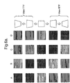
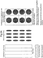
- Figure 6b illustrates an example in which the image strips are not registered.
- the angle at which the different views occur depend upon the position of the strips under the lenses and Figure 6b shows four possible variations depending on this position.
- variant A is for the case where the registration is exact and two image strips sit under a singe lens.
- a transient states (TI) exists between the two switching positions, in this case where this is no tilt.
- Variant D is also for the case where the registration is exact but in this case the image strips are inverted relative to their position in variant A.
- Variants B and C show intermediate positions between variants A and D where the strips only partly sit under a single lens.
- the advantage of the current invention is that whatever the registration the viewer will always observe the complementary switch between the image and the background. This is contrast to the related art where there is no image and background and therefore no complementary switch between an image and a background region. In this case the authentication relies completely on the switch of the single region and the angle at which this occurs.
- Figure 6a illustrates an example of the related art with different degrees of registration between the image strips and microlenses.
- variants A and B are for the case where the registration is exact and two image strips sit under a singe lens and one colour is observed by tilting forward (TTF) and a different colour observed by tilting backward (BTF).
- TTF tilting forward
- BTF tilting backward
- TI transient state
- the switch from one colour to another occurs only when the device is tilted significantly away from the non-tilted position and therefore may not be observed by the authenticator.
- Figure 26 illustrates a similar embodiment to that shown in Figure 6b but where the image elements which form the background in Figure 6b now alternatively form a second image in Figure 26 .
- the device in Figure 26 at a first viewing angle 21 displays a red star symbol and a blue numeral five.
- the two images are inverted so that the star symbol is blue and the numeral five is red.
- the device comprises two views A and B where the image elements in the strips forming view A in the region of the star are red and in the region of the numeral five are blue, and conversely the image elements in strips forming view B in the region of the star are blue and in the region of the numeral five are red.
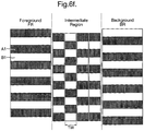
- an intermediate region such as a boundary region is created between the star and the background and this is shown in Figure 6c .
- the foreground region (FR) is the region inside the star
- the background region (BR) is the region outside the star
- the intermediate region (IR) is between the star and the background.
- Figure 6d shows the image strips in this intermediate region.
- the image strip A1 it will be seen that in the background region (BR) 12 the strip is white but in the symbol region (FR) 10 it changes to black. However in the intermediate region the strip is half black and half white. In contrast, the image strip B1 is black in the background region (BR) 12 and white in the symbol region (FR) 10 and in the intermediate region is half white and half black in a inverse pattern of the intermediate region in A1. There is therefore a lateral quarter-shift between the lines of the symbol and the intermediate region and the lines of background and the intermediate region.
- Figure 6e shows the behaviour of a device with the grid structure in Figure 6d .
- the black elements associated with the IR are centred under the lenslets.
- the intermediate region will be visible providing a dark outline of the image
- the device will switch in the manner described with reference to Figure 4A .
- the IR will be in a transient state between the white and black colours.
- the white elements associated with the IR are centred under the lenslets and thus a white outline of the image is provided in the transient state.
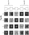
- Figure 6f shows a further embodiment of the IR such that the colour of the IR region does not change on tilting.
- the linear line or grid system in the IR region is divided into a sub grid system of width TW.
- the image strip A1 the top half of the image strip in the IR is predominantly white with a black region of width TW, and the bottom half of the strip is predominantly black with a white region of width TW.
- Strip B1 is the inverse of strip A1.
- TW has a dimension less than that which can be visualised with the naked eye the observer will visualise colourmixing.
- the width of TW is preferably in the range 10-100 ⁇ m and even more preferably 20-50 ⁇ m.
- Figure 6g shows the behaviour of a device with the grid structure in Figure 6f and shows that the boundary line to the star (IR) remains fixed in colour on tilting.
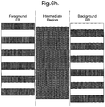
- Figures 6h and 6i show an alternative embodiment where the IR is provided with a uniform colourant which in this case is the black colour. In this case the IR will remain black on tilting as shown in Figure 6i .
- Figure 7a illustrates a further example of a security device according to the invention.
- two lenticular devices 20,22 according to examples of the invention are provided side by side and when visible at any particular viewing angle will exhibit contrasting colours.
- the device 20 at a first viewing angle 21 displays a red star symbol against a blue background while the device 22 displays a blue star symbol against a red background.
- each device has exhibited a respective colour switch so that the star symbol of the device 20 is blue against a red background while the star symbol of the device 22 is red against a blue background.
- Figure 7a Whilst the first example provides a simple way for an observer to validate the device by noting the colour switch, the device of Figure 7a provides even more security by requiring complementary colour shifts between two devices. This provides a very valuable device in view of its ease of verification and the fact that the feature being verified, which is the complementary colour shifts between two devices, does not require exact registration between the image, strips and the focussing elements.
- Figure 19 shows the use of the concept described in Figures 6b and 7a for use on a security thread. In this case images 1 and 2 and the complementary background regions are periodically repeated along the long axis of the thread or strip such that image 1 and image 2 are viewable in alternate windows of the security document.
- the image and its complementary switch are seen on tilting the device and this is illustrated in Figure 20 for the case where the device is tilted forward and in Figure 21 for the case where the device is tilted backward. It can be seen on tilting forwards and then backward the observer see the inversion of the images in each window.
- Figure 7b illustrates a further example similar to that shown in Figure 7a but for the case where the two lenticular devices display different images, i.e. lenticular device 22 has been replaced with lenticular device 23 which displays a blue numeral 5 against a red background. The rest of the device remains the same as shown in Figure 7a .
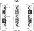
- FIG 8 Another example of a security device according to the invention is shown in Figure 8 , in this case in the form of a security thread.
- the device comprises five lenticular devices 30-34 abutting one another.
- the devices 31,33 are constructed in accordance with the device of Figure 4 and exhibit complementary colour shifts with respect to each other (as described with reference to Figure 7 ).
- the cylindrical lenses of the devices 31,33 extend vertically.
- the lenticular devices 30,32,34 are of a conventional construction and define chevron style images beneath cylindrical lenses which extend vertically. The same cylindrical lenses could be used for all five devices.
- the image strips beneath the cylindrical lenses of the devices 30,32,34 are provided so as to give the effect of a moving image when the security device is tilted to the left or right as shown in Figure 8 . During this tilting process, the appearance of the devices 31,33 will also switch.
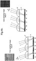
- Figure 9 is a cross-section through part of the device of Figure 8 .
- the image elements in the strips are generated using diffractive relief structures.
- the device comprises sets of cylindrical lenses 2 (as before) on a transparent substrate 4. Under each lens defining the devices 31,33, are provided two image strips A,B having the form shown in Figure 5 .
- each lens corresponding to the devices 30,32,34 are provided a plurality (in this case six) of image strips A-F defining the movement effect of the chevron.
- the cylindrical lenses of the devices 31,33 and the cylindrical lenses of the devices 30,32,34 could extend in different directions for example the cylindrical lenses of the devices 31 and 33 could extend horizontally and the cylindrical lenses of the devices 30,32,34 could extend vertically.
- the devices 30,32 and 34 When such a security device is tilted to the left or right, i.e. rotating around axis 1, the devices 30,32 and 34 will give the effect of a moving image but the appearance of the devices 31,33 will remain unchanged.
- the security device is tilted towards and away from the viewer, i.e. rotating around axis 2
- the devices 31,33 will exhibit the colour switching effect described earlier but the appearance of the devices 30,32,34 will remain unchanged.
- the image elements in strips A and B for devices 31 and 33 do not have to be formed by relief structures and could be formed by conventional printing techniques. This is also the case for devices 30, 32 and 34 but the use of relief structures is very much preferred in order to achieve the small strip widths necessary for a lenticular animation effect in a thin device.
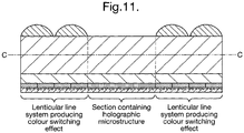
- Figures 10 and 11 are similar to Figures 8 and 9 but illustrating another example.
- holographic generating structures 36,38,40 are interleaved around two lenticular devices 31,33 having the same form as the devices 31,33 shown in Figure 8 .
- the lenticular devices 31,33 When the device is tipped towards and away from the viewer (rotating around axis 2), however, the lenticular devices 31,33 will exhibit their colour switching effect but the holographic images will remain unchanged.
- the lenticular devices 31,33 are provided by sets of image strips A,B registered with the lenses 2 while the holographic microstructure 50 of each device 36,38,40 is located beneath part of the substrate 4 on which there are no lenses.
- the holographic generating structures 36,38,40 can be in the form of holograms or DOVID image elements.
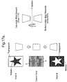
- Figure 12A illustrates image regions of the strips (IM) in the form of embossed or recessed lines while the non-embossed lines correspond to the non-imaged regions of the strips (NI).
- Figure 12B illustrates image regions of the strips (IM) in the form of debossed lines or bumps.
- the relief structures of the image regions can be in the form of diffraction gratings ( Figure 12C ) or moth-eye/fine pitch gratings ( Figure 12D ).
- the image regions (IM) of Figures 12A and 12B can be further provided with gratings as shown in Figures 12E and 12F respectively.
- Figure 12G illustrates the use of a simple scattering structure in the image regions IM providing an achromatic effect.
- the recesses of the image regions (IM) of Figure 12A could be provided with an ink or the debossed regions or bumps of Figure 12B could be provided with an ink.
- the latter is shown in Figure 12H where ink layers 100 are provided on the bumps.
- Figure 12I illustrates the use of an Aztec structure on the image regions (IM).
- image and non-image areas or regions could be defined by combinations of different elements types, e.g. the image areas could be formed from moth-eye structures whilst the non-image areas could be formed from a grating. Or even the image and non-image areas could be formed by gratings of different pitch or orientation.
- the height or depth of the bumps/recesses is preferably in the range 0.5-10 ⁇ m and more preferably in the range 1-5 ⁇ m.
- Typical widths of the bumps/recesses will be defined by the nature of the artwork but would typically be less than 100 ⁇ m, more preferably less than 50 ⁇ m and even more preferably less than 25 microns.
- the width of the image strip and therefore the width of the bumps or recesses will be dependent on the type of optical effect required for example if the diameter of the focussing elements is 30 ⁇ m then a simple switch effect between two views A and B could be achieved using 15 ⁇ m wide image strips.
- one or more of the holographic generating structures could be replaced by moire magnification structures which could be either 2 - dimensional (2D) or 1 - dimensional (1D) structures.
- 2D moire magnification structures are described in more detail in EP-A-1695121 and WO-A-94/27254 .
- a moire magnification device is constructed through a combination of microlenses and microimages. In the simplest case of a small pitch mismatch between the lens arrays and image arrays, an array of magnified images of constant magnification is observed with motion resulting from the normal parallax of a lens.
- a 1D moire magnification structure the 2D spherical lens array used in a conventional 2D moire magnification structure is replaced with a repeating arrangement of cylindrical lens-lets.
- the micro-image elements are subject to moire magnification in one axis only which is the axis along which the lenses exhibit their periodic variations in curvature or relief. Consequently the micro-images are strongly compressed or de-magnified along the magnification axis whilst the size or dimension of the micro image elements along the axis orthogonal to the magnification axis is substantially the same as they appear to the observer - i.e. no magnification or enlargement takes place.
- the moire magnified image to be comprised of an array of circles 2mm in diameter.
- the periodicity and alignment of the micro image array relative to the micro -lens array to provide a moire magnification of x50.
- the axis of lens curvature of the lenses to be the x-axis it then follows that the micro image array will be comprised of a matrix of elliptical image elements wherein the minor axis of the ellipse (coinciding with the x-axis) will have a width of 0.04mm and a height of 2mm.
- parallax motion of the circular images (as well as magnification) will occur along the x-axis on east-west tilting of the device. It should be noted that on north-south tilting of the device no parallax motion will be exhibited. Conversely if the cylindrical lens system and micro-image array are rotated by 90 degrees then parallax motion will take place along the y-axis on north south tilting of the device.
- microlens array and microimage array such that the axis of parallax lies at 45 degrees to the x or y- axis or any angle in between which may be deemed advantageous.
- a 1D moire magnification device with a lenticular structure is particularly advantageous because they both comprise a lenticular lens array and therefore the same lens array can be used for both regions of the device.
- the lenticular structure could exhibit a simple image switch and the 1D moire magnifier will exhibit a parallax motion effect.
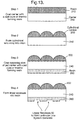
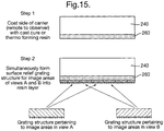
- a carrier layer 240 such as a PET layer is coated with a cast-cure or thermoforming resin 210 (step 1).
- This resin 210 is then (step 2) cast or embossed into a cylindrical lens array 200.
- the other side of the carrier 240 is then coated with a cast-cure or thermoforming resin 260 (step 3) and recesses 50 corresponding to the image elements in strips A and B are formed by casting or embossing in the resin layer (step 4) in register with the lenses 200.
- a roll of clear polymeric film 240 of PET or the like is coated on its first surface with a layer 210 of UV curable polymer.
- Suitable UV curable polymers include photopolymer NOA61 available from Norland Products, Inc. New Jersey, Xymara OVD primer from Ciba or UV9206 from Akzo-Nobel.
- the film is then brought into contact with a first embossing roller that contains the negative of a master structure for the microlens array 200.
- the microlens array structure 200 is replicated in the UV curable polymer layer 210.
- the UV curable polymer layer is cured by application of UV radiation and the coated film is then released from the embossing roller.
- a layer 260 of UV curable polymer such as NOA61 is then coated onto the opposite second surface of the film 240.
- the second surface of the film is then brought into contact with a second embossing roller that contains the negative of a master structure for the image elements of the image strips.
- the image structure is replicated in the UV curable polymer layer on the second surface of the clear polymeric film.
- the UV curable polymer layer is cured by application of UV radiation and the coated film is then released from the embossing roller.
- a uniform pigmented or dyed coating is applied to the embossed surface of the layer 260 using a first opaque colorant 52 such as pigmented version of the casting resins above or for example a gravure ink such as 60473G from Luminescence which will fill the recesses 50 and provide a coating over the entire layer 26 (step 4).
- the coating method is typically by gravure, litho or flexographic printing or by using an anilox roller.
- step 6 excess first colorant 52 is removed using a doctor blade process so as to leave the first colorant only in the recesses 50 which form the image elements within the strips.
- a second colorant 54 in the form of a pigmented or dyed coating such as pigmented version of the casting resins above or for example a gravure ink such as 60473G from Luminescence is coated over the resin layer 260 typically using a litho, flexographic or gravure process so that in the non-image regions of the strip the second colorant 54 will be visible through the lenses 200 while in of the image regions first colorant 52 will be visible. The observer will therefore see a coloured image against a differently coloured background.
- FIG 14 illustrates a modified form of the method.
- steps 1-4 are as previously described with reference to Figure 13 .
- a first colorant 52 is transferred onto the non-recessed linear regions of the layer 260 using an offset transfer method from an anilox roller or litho blanket, or by litho, flexographic or gravure printing.
- a second colorant 54 is uniformly coated onto the layer 260 so that it also fills the recesses 50 (step 6A). This can be carried out using a gravure or offset litho process, etc.
- the second colorant 50 will define the image elements and the first colorant 52 will define the non-image elements and therefore form the coloured background region.
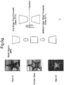
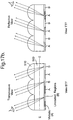
- Figure 15 illustrates an alternative method in which the image strips are formed by diffractive surface reliefs.
- step 1 a carrier layer 240 is coated with cast-cure or thermoforming resin layer 260.
- the device illustrated has Strips A and B, representing views A and B of a lenticular switching device, comprising image and non-image regions.
- Strips A the image regions are defined by one grating structure X and in Strips B the image regions are defined by a second different grating structure Y.
- the grating structures X,Y which have been previously originated are then simultaneously formed by embossing into the exposed surfaces of the resin layer 260 (step 2).
- the use of two different grating structures for the image regions of A and B provides a visual contrast due to the different diffractive colour effects. This difference is not essential and the image regions could be defined by the same diffractive grating structure.
- the non-image regions could also be defined by a grating structure which is different to that of the image regions.
- the grating structures could differ for example by rotation and pitch.
- a reflection coating layer 60 is then provided over the grating surface relief structure (step 3).
- This reflection coating can be a metallisation or a high refractive index layer.
- high refractive index materials typically inorganic, are well known in the art and described in US4856857 .
- Typical examples of materials suitable for the high refractive index layer include zinc sulphide, titanium dioxide and zirconium dioxide. Replacing the vapour deposited metal reflection enhancing layer with a transparent hri layer is particularly beneficial when the security device of the current invention is applied over transparent regions (typically known as apertures or windows) of secure documents.
- the other side of the carrier layer 240 is then coated with a cast-cure or thermoforming resin 210 (step 4) and then a set of cylindrical lenses 200 are embossed into the layer 21 (step 5) so as to be in register with the strips A and B.
- cylindrical lenses have been used as the lenticular focusing elements. It should be understood, however, that they could be replaced by micromirrors.
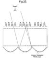
- Figure 25 illustrates a typical cross-section of the security device of the current invention which utilises micromirrors as the focussing elements.
- a series of micromirrors 600 are formed in thermoforming resin 610 by casting a set of cylindrical lenses as described previously and then vapour depositing a layer of metal on the back surface.
- the lenticular device comprises four image strips A-D formed on the top surface of the device where the image regions of these strips are creating by printing on raised regions (bumps).
- the security device of the current invention can be made machine readable by the introduction of detectable materials in any of the layers or by the introduction of separate machine-readable layers.
- Detectable materials that react to an external stimulus include but are not limited to fluorescent, phosphorescent, infrared absorbing, thermochromic, photochromic, magnetic, electrochromic, conductive and piezochromic materials.
- the security device of the current invention may also comprise additional security features such as any desired printed images, metallic layers which may be opaque, semitransparent or screened. Such metallic layers may contain negative or positive indicia created by known demetallisation processes.
- Additional optically variable materials can be included in the security device such as thin film interference elements, liquid crystal material and photonic crystal materials. Such materials may be in the form of filmic layers or as pigmented materials suitable for application by printing.
- Figures 16a and b show a second security feature in the form of a demetallised image incorporated within a security device of the current invention.
- the security thread shown in figure 16a has regions 400 comprising complementary lenticular switching devices and regions 410 comprising demetallised indicia.
- a metallised layer 420 has been applied over the layer comprising the image forming relief structures 430 between a lenslet array 440.
- the metal layer 420 provides two benefits. Firstly it may improve the brightness and contrast of the image elements formed by the relief structures 430, this is particularly the case if diffractive relief structures are used to form the image elements. Secondly it allows the creation of demetallised indicia which can be viewed in reflective but more preferably transmitted light. In the example shown the demetallised indicia 410 are shown in a separate region of the device to the lenticular effect however in an alternative embodiment the two effects could be superimposed.
- One way to produce partially metallised/demetallised films in which no metal is present in controlled and clearly defined areas is to selectively demetallise regions using a resist and etch technique such as is described in US-B-4652015 .
- Other techniques are known for achieving similar effects; for example aluminium can be vacuum deposited through a mask, or aluminium can be selectively removed from a composite strip of a plastic carrier and aluminium using an excimer laser.
- the metallic regions may be alternatively provided by printing a metal effect ink having a metallic appearance such as Metalstar® inks sold by Eckart.
- a metallic layer can be used to conceal the presence of a machine readable dark magnetic layer.
- a magnetic material When a magnetic material is incorporated into the device the magnetic material can be applied in any design but common examples include the use of magnetic tramlines or the use of magnetic blocks to form a coded structure.
- Suitable magnetic materials include iron oxide pigments (Fe 2 O 3 or Fe 3 O 4 ), barium or strontium ferrites, iron, nickel, cobalt and alloys of these.
- alloys includes materials such as Nickel:Cobalt, Iron:Aluminium:Nickel:Cobalt and the like.
- Flake Nickel materials can be used; in addition Iron flake materials are suitable. Typical nickel flakes have lateral dimensions in the range 5-50 microns and a thickness less than 2 microns. Typical iron flakes have lateral dimensions in the range 10-30 microns and a thickness less than 2 microns.
- a transparent magnetic layer can be incorporated at any position within the device structure.
- Suitable transparent magnetic layers containing a distribution of particles of a magnetic material of a size and distributed in a concentration at which the magnetic layer remains transparent are described in WO03091953 and WO03091952 .
- the security device of the current invention may be incorporated in a security document such that the device is incorporated in a transparent region of the document.
- the security document may have a substrate formed from any conventional material including paper and polymer. Techniques are known in the art for forming transparent regions in each of these types of substrate.
- WO8300659 describes a polymer banknote formed from a transparent substrate comprising an opacifying coating on both sides of the substrate. The opacifying coating is omitted in localised regions on both sides of the substrate to form a transparent region.
- EP1141480 describes a method of making a transparent region in a paper substrate. Other methods for forming transparent regions in paper substrates are described in EP0723501 , EP0724519 , EP1398174 and WO03054297 .
- the contrast between the first and second images is achieved by leaving one of the image elements uncoated.
- the image strip A1 in this example in the background region 12 the strip is black but in the symbol region 10 the strip will remain uncoated.
- the image strip B1 is uncoated in the background region 12 and black in the symbol region 10. This lateral half-shift between the lines of the symbol and background means that a complementary switch from black to colourless will occur as the device is tilted in the manner shown in Figure 4A . If the remaining layers of the device are substantially transparent then a complementary switch from black to transparent can be observed.
- the black images described in the example above could be replaced with highly reflective material such as a metallic material and again the complementary image regions will remain uncoated such that with reference to Figure 5 and considering first the image strip A1, in this example in the background region 12 the strip is metallic but in the symbol region 10 the strip will remain uncoated. In contrast, the image strip B1 is uncoated in the background region 12 and metallic in the symbol region 10.
- This lateral half-shift between the lines of the symbol and background means that a complementary switch from metallic to colourless will occur as the device is tilted in the manner shown in Figure 17a . If the remaining layers of the device are substantially transparent then a complementary switch from metallic to transparent can be observed.
- the switch from metallic to transparent is optimised if the width of the metallic (A) and uncoated (B) strips are not the same and preferably the ratio of the width of the metallic strips to the uncoated strips is in the range 25-35:75-65.
- the metallic regions could be formed by the vapour deposition of a thin metallic layer through a mask or by forming the uncoated regions through a demetallisation process. Alternatively a metallised set of lines may be generated by using lenses to photo-ablate the metal. It is also possible that the metallic regions can be created using a printed metallic ink.
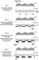
- FIG 18 shows an example of the demetallisation method.
- step 1 recesses 520 are formed using a cast cure process in a resin layer 530.
- the recesses 520 correspond to the non-metallised regions in the final device.
- step 2 the whole surface of the resin layer is coated with an aluminium layer 540 preferably by a vapour deposition process.
- step 3 the non-recessed regions are coated with a layer of resist 560, this typically done using a lithographic or gravure printing process.
- step 4 the structure is immersed in a metal etchant such as a concentrated sodium hydroxide solution and the aluminium in the regions not covered by resist is removed. The remaining resist 560 is then removed to leave a device comprising metallic and non-metallic regions.
- a metal etchant such as a concentrated sodium hydroxide solution
- Figure 17a shows a device comprising an image or background region this is not essential and the device could simply comprise a uniform grid of metallic lines separated by uncoated transparent regions. Such a device would switch from uniformly transparent to metallic on tilting.
- Such a metallic to transparent switching device could be applied over other indicia on a secure document such that at one angle of view, when the device appears metallic, the other indicia are concealed and at a second angle of view the device appears transparent and the underlying indicia is revealed.
Landscapes
- Physics & Mathematics (AREA)
- Accounting & Taxation (AREA)
- Finance (AREA)
- Business, Economics & Management (AREA)
- General Physics & Mathematics (AREA)
- Optics & Photonics (AREA)
- Engineering & Computer Science (AREA)
- Manufacturing & Machinery (AREA)
- Printing Methods (AREA)
- Credit Cards Or The Like (AREA)
- Holo Graphy (AREA)
- Stereoscopic And Panoramic Photography (AREA)
- Burglar Alarm Systems (AREA)
- Closed-Circuit Television Systems (AREA)
- Testing, Inspecting, Measuring Of Stereoscopic Televisions And Televisions (AREA)
Priority Applications (1)
| Application Number | Priority Date | Filing Date | Title |
|---|---|---|---|
| PL10775854T PL2493698T3 (pl) | 2009-10-30 | 2010-10-27 | Urządzenia zabezpieczające i sposoby ich wytwarzania |
Applications Claiming Priority (3)
| Application Number | Priority Date | Filing Date | Title |
|---|---|---|---|
| US27277409P | 2009-10-30 | 2009-10-30 | |
| GBGB0919112.3A GB0919112D0 (en) | 2009-10-30 | 2009-10-30 | Security device |
| PCT/GB2010/001993 WO2011051668A1 (en) | 2009-10-30 | 2010-10-27 | Security device |
Publications (2)
| Publication Number | Publication Date |
|---|---|
| EP2493698A1 EP2493698A1 (en) | 2012-09-05 |
| EP2493698B1 true EP2493698B1 (en) | 2018-10-10 |
Family
ID=41434972
Family Applications (1)
| Application Number | Title | Priority Date | Filing Date |
|---|---|---|---|
| EP10775854.2A Active EP2493698B1 (en) | 2009-10-30 | 2010-10-27 | Security devices and methods of manufacturing them |
Country Status (12)
| Country | Link |
|---|---|
| US (1) | US9429762B2 (enExample) |
| EP (1) | EP2493698B1 (enExample) |
| JP (1) | JP5788886B2 (enExample) |
| CN (1) | CN102712205B (enExample) |
| AU (1) | AU2010311162B2 (enExample) |
| CA (1) | CA2778914C (enExample) |
| EA (1) | EA024800B1 (enExample) |
| GB (1) | GB0919112D0 (enExample) |
| IN (1) | IN2012DN02748A (enExample) |
| MX (1) | MX2012004699A (enExample) |
| PL (1) | PL2493698T3 (enExample) |
| WO (1) | WO2011051668A1 (enExample) |
Cited By (1)
| Publication number | Priority date | Publication date | Assignee | Title |
|---|---|---|---|---|
| WO2022174982A1 (de) | 2021-02-19 | 2022-08-25 | Giesecke+Devrient Currency Technology Gmbh | Verfahren zur herstellung eines sicherheitselements mit mikroabbildungselementen |
Families Citing this family (59)
| Publication number | Priority date | Publication date | Assignee | Title |
|---|---|---|---|---|
| GB2495686B (en) * | 2010-08-23 | 2016-12-28 | Innovia Security Pty Ltd | Multichannel opticallly variable device |
| GB201107657D0 (en) * | 2011-05-09 | 2011-06-22 | Rue De Int Ltd | Security device |
| US9171392B2 (en) * | 2011-08-02 | 2015-10-27 | Tracer Imaging Llc | Lenticular product having a radial lenticular blending effect |
| BR112014003888A2 (pt) | 2011-08-19 | 2017-03-21 | Visual Physics Llc | sistema ótico opcionalmente transferível com uma espessura reduzida |
| ES2423104B1 (es) * | 2012-02-14 | 2014-07-09 | Fermin Sanchez Rodriguez | Procedimiento de formación de imágenes o leyendas por superposición |
| RU2640716C9 (ru) | 2012-04-25 | 2019-03-25 | Визуал Физикс, Ллс | Защитное устройство для проецирования набора синтетических изображений |
| JP2014526711A (ja) * | 2012-06-12 | 2014-10-06 | メディア レリーフ | 玉虫色画像を作り出す方法、結果として生じる画像、その玉虫色画像を備えたデバイス、及び関連するプログラム |
| AU2012100985B4 (en) * | 2012-06-29 | 2012-11-15 | Ccl Secure Pty Ltd | Optically variable colour image |
| DE102012215475A1 (de) * | 2012-08-31 | 2014-03-06 | Bundesdruckerei Gmbh | Sicherheitsdokument mit mehrfarbigem und zweiseitigem Sicherheitsmerkmal |
| US9280656B2 (en) * | 2012-11-16 | 2016-03-08 | University-Industry Foundation, Yonsei University | Device and method for providing security channel interface |
| GB2514338B (en) | 2013-05-17 | 2020-06-10 | De La Rue Int Ltd | Security documents and methods of manufacture |
| GB201313363D0 (en) | 2013-07-26 | 2013-09-11 | Rue De Int Ltd | Security devices and method of manufacture |
| GB201313362D0 (en) * | 2013-07-26 | 2013-09-11 | Rue De Int Ltd | Security Devices and Methods of Manufacture |
| DE102014004700A1 (de) | 2014-03-31 | 2015-10-01 | Giesecke & Devrient Gmbh | Sicherheitselement mit einem Linsenrasterbild |
| JP6375749B2 (ja) * | 2014-07-18 | 2018-08-22 | 大日本印刷株式会社 | 表示物 |
| JP5743248B1 (ja) * | 2014-10-10 | 2015-07-01 | グラパックジャパン株式会社 | 部分光学素子配列を備えた画像表示体、部分光学素子配列形成方法 |
| EP3210069A4 (en) | 2014-10-24 | 2018-05-30 | Wavefront Technology, Inc. | Optical products, masters for fabricating optical products, and methods for manufacturing masters and optical products |
| DE102014018512A1 (de) | 2014-12-12 | 2016-06-16 | Giesecke & Devrient Gmbh | Optisch variables Sicherheitselement |
| WO2016114367A1 (ja) * | 2015-01-15 | 2016-07-21 | 富士フイルム株式会社 | レンチキュラーシート、及びその製造方法、並びにレンチキュラー表示体 |
| GB2536877B (en) * | 2015-03-23 | 2017-06-28 | De La Rue Int Ltd | Security device and method of manufacture |
| AU2016248847B2 (en) * | 2015-04-16 | 2021-07-15 | Rolic Ag | Multiple image scattering device |
| KR102408530B1 (ko) * | 2015-06-02 | 2022-06-13 | 도판 인사츠 가부시키가이샤 | 적층체 및 그 제조 방법 |
| GB201512122D0 (en) * | 2015-07-10 | 2015-08-19 | Rue De Int Ltd | Methods and apparatus for forming non-diffractive light control structures in or on a surface of a polymer substrate |
| MA42904A (fr) | 2015-07-10 | 2018-05-16 | De La Rue Int Ltd | Procédés de fabrication de documents de sécurité et de dispositifs de sécurité |
| EP3320385B1 (en) | 2015-07-13 | 2020-11-04 | Wavefront Technology, Inc. | Optical products |
| MA43350A (fr) * | 2015-10-02 | 2018-08-08 | De La Rue Int Ltd | Dispositif de sécurité |
| GB201520085D0 (en) | 2015-11-13 | 2015-12-30 | Rue De Int Ltd | Methods of manufacturing image element arrays for security devices |
| WO2017099007A1 (ja) * | 2015-12-08 | 2017-06-15 | 株式会社エンプラス | マーカ |
| US10324023B1 (en) * | 2015-12-14 | 2019-06-18 | Spectroclick, Inc. | Energy dispersion cuvette |
| GB2547045A (en) * | 2016-02-08 | 2017-08-09 | De La Rue Int Ltd | Improvements in security devices |
| EP3405353A4 (en) | 2016-04-22 | 2019-11-06 | Wavefront Technology, Inc. | OPTICAL SWITCHING DEVICES |
| GB2550168B (en) * | 2016-05-11 | 2018-07-25 | De La Rue Int Ltd | Security device and method of manufacture |
| DE102016109193A1 (de) * | 2016-05-19 | 2017-11-23 | Ovd Kinegram Ag | Verfahren zur Herstellung von Sicherheitselementen mit einem Lenticular Flip |
| GB201612290D0 (en) * | 2016-07-15 | 2016-08-31 | La Rue Int De Ltd | Methods of manufacturing a secuirty device |
| EP4600707A3 (en) | 2016-08-31 | 2025-11-19 | Viavi Solutions Inc. | Article with angled reflective segments |
| DE112017005555T5 (de) * | 2016-12-02 | 2019-08-01 | Rolling Optics Innovation Ab | Vorrichtung für synthetische bilder mit verriegelungsmerkmalen |
| KR102489526B1 (ko) | 2017-02-10 | 2023-01-17 | 크레인 앤 코, 인크 | 머신 판독가능 광학적 보안 디바이스 |
| GB2562775B (en) * | 2017-05-25 | 2021-06-02 | De La Rue Int Ltd | Holographic security device and method of manufacture thereof |
| AU2017100907B4 (en) * | 2017-07-03 | 2018-02-08 | Ccl Secure Pty Ltd | Micro-optic device projecting multi channel projected imagery |
| US10838218B2 (en) | 2017-10-05 | 2020-11-17 | Wavefront Technology, Inc. | Optical structures providing dichroic effects |
| GB2567680B (en) * | 2017-10-20 | 2022-12-21 | Pulsetech Security Ltd | Holograms |
| CA3073365A1 (en) | 2017-10-20 | 2019-04-25 | Wavefront Technology, Inc. | Optical switch devices |
| AU2018100225A4 (en) | 2018-02-21 | 2018-03-22 | Ccl Secure Pty Ltd | Micro-imagery design integration |
| AU2019408423B2 (en) * | 2018-12-21 | 2024-10-17 | Karmic Sàrl | Device for displaying one or more transitory images from three-dimensional microstructures and uses of such a device |
| WO2020162079A1 (ja) * | 2019-02-06 | 2020-08-13 | 富士フイルム株式会社 | 画像表示体 |
| WO2020205053A1 (en) | 2019-04-04 | 2020-10-08 | Wavefront Technology, Inc. | Optical structures providing dichroic effects |
| CA3134512A1 (en) | 2019-04-19 | 2020-10-22 | Wavefront Technology, Inc. | Optical switch devices |
| EP3766702A1 (en) * | 2019-07-15 | 2021-01-20 | Giesecke+Devrient Currency Technology GmbH | Security element and method for manufacturing it |
| US11685180B2 (en) | 2019-08-19 | 2023-06-27 | Crane & Co., Inc. | Micro-optic security device with zones of color |
| CN112848744B (zh) * | 2019-11-28 | 2022-04-29 | 中钞特种防伪科技有限公司 | 光学防伪元件及防伪产品 |
| KR20220133181A (ko) * | 2019-12-18 | 2022-10-04 | 크레인 앤 코, 인크 | 위상 정렬된 이미지 층들을 갖는 마이크로 광학 보안 디바이스 |
| CN110906176A (zh) * | 2019-12-27 | 2020-03-24 | 北京夏禾科技有限公司 | 一种oled透镜照明模组及其制备方法 |
| DE102020113144A1 (de) * | 2020-05-14 | 2021-11-18 | Leonhard Kurz Stiftung & Co. Kg | Verfahren zum Herstellen eines Mehrschichtkörpers sowie ein Mehrschichtkörper |
| US11577540B2 (en) * | 2020-05-29 | 2023-02-14 | Capital One Services, Llc | Financial card with dynamic viewing angles to block card information |
| DE102020004423A1 (de) * | 2020-07-22 | 2022-01-27 | Giesecke+Devrient Currency Technology Gmbh | Sicherheitsmerkmal mit kippungsabhängiger Motivdarstellung |
| US12253691B2 (en) | 2020-10-07 | 2025-03-18 | Wavefront Technology, Inc. | Optical products, masters for fabricating optical products, and methods for manufacturing masters and optical products |
| EP4217792A4 (en) | 2020-10-07 | 2024-10-30 | Wavefront Technology, Inc. | OPTICAL PRODUCTS, MATRICES FOR THE MANUFACTURE OF OPTICAL PRODUCTS AND METHODS FOR THE MANUFACTURE OF MATRICES AND OPTICAL PRODUCTS |
| GB202101267D0 (en) * | 2021-01-29 | 2021-03-17 | De La Rue Int Ltd | Security devices and methods of manufacture thereof |
| DE102022000785A1 (de) * | 2022-03-07 | 2023-09-07 | Giesecke+Devrient Currency Technology Gmbh | Sicherheitselement für ein Wertdokument, Wertdokument und Verfahren zur Herstellung eines Sicherheitselements |
Citations (22)
| Publication number | Priority date | Publication date | Assignee | Title |
|---|---|---|---|---|
| US2799938A (en) | 1954-02-09 | 1957-07-23 | Pictorial Prod Inc | Evaluating device |
| US4417784A (en) | 1981-02-19 | 1983-11-29 | Rca Corporation | Multiple image encoding using surface relief structures as authenticating device for sheet-material authenticated item |
| US4765656A (en) | 1985-10-15 | 1988-08-23 | Gao Gesellschaft Fur Automation Und Organisation Mbh | Data carrier having an optical authenticity feature and methods for producing and testing said data carrier |
| US4959641A (en) | 1986-09-30 | 1990-09-25 | Bass Martin L | Display means for stereoscopic images |
| WO1994027254A1 (en) | 1993-05-11 | 1994-11-24 | De La Rue Holographics Limited | Security device |
| US5924870A (en) | 1996-12-09 | 1999-07-20 | Digillax Systems | Lenticular image and method |
| US6000332A (en) | 1997-09-30 | 1999-12-14 | Cyrk, Inc. | Process for achieving a lenticular effect by screen printing |
| US6091482A (en) | 1997-05-22 | 2000-07-18 | Reynolds Metals Company | Method of mapping and interlacing images to a lenticular lens |
| US6177953B1 (en) | 1997-06-26 | 2001-01-23 | Eastman Kodak Company | Integral images with a transition set of images |
| US6251566B1 (en) | 1996-12-09 | 2001-06-26 | Scott Brosh | Cylindrical lenticular image and method |
| US6329987B1 (en) | 1996-12-09 | 2001-12-11 | Phil Gottfried | Lenticular image and method |
| JP2002019255A (ja) | 2000-07-11 | 2002-01-23 | Dainippon Printing Co Ltd | 潜像表示媒体 |
| US6414794B1 (en) | 1995-01-18 | 2002-07-02 | Bruce A. Rosenthal | Lenticular optical system |
| WO2003052680A1 (en) | 2001-12-18 | 2003-06-26 | Digimarc Id System, Llc | Multiple image security features for identification documents and methods of making same |
| US20040195823A1 (en) | 2001-08-06 | 2004-10-07 | Takao Yokote | Authenticatable printed matter and its production method |
| WO2005052650A2 (en) | 2003-11-21 | 2005-06-09 | Nanoventions, Inc. | Micro-optic security and image presentation system |
| JP3111699U (ja) | 2005-04-20 | 2005-07-28 | 株式会社ハーベストン | 絵柄変えカード |
| JP2006272602A (ja) | 2005-03-28 | 2006-10-12 | National Printing Bureau | 真偽判別可能な印刷物 |
| WO2006110038A2 (en) | 2005-04-14 | 2006-10-19 | Sdu Identification B.V. | Identity document and method for the manufacture thereof |
| DE102005039113A1 (de) | 2005-08-18 | 2007-02-22 | Zintzmeyer, Jörg | Mikro-Refraktionsbild |
| US20080284157A1 (en) | 2005-03-29 | 2008-11-20 | Sani Muke | Tamper Evident Identification Documents |
| WO2010099571A1 (en) | 2009-03-04 | 2010-09-10 | Securency International Pty Ltd | Improvements in methods for producing lens arrays |
Family Cites Families (26)
| Publication number | Priority date | Publication date | Assignee | Title |
|---|---|---|---|---|
| GB1552853A (en) | 1976-09-24 | 1979-09-19 | Bank Of England | Authentication devices |
| US4402150A (en) | 1981-05-11 | 1983-09-06 | Polaroid Corporation | Verification device |
| CA1272231A (en) | 1981-08-24 | 1990-07-31 | Mario Girolamo | Bank notes and the like |
| EP0609683A1 (en) | 1985-05-07 | 1994-08-10 | Dai Nippon Insatsu Kabushiki Kaisha | Relief hologram and process for producing a relief hologram |
| US4652015A (en) | 1985-12-05 | 1987-03-24 | Crane Company | Security paper for currency and banknotes |
| DE3609090A1 (de) | 1986-03-18 | 1987-09-24 | Gao Ges Automation Org | Wertpapier mit darin eingelagertem sicherheitsfaden und verfahren zur herstellung derselben |
| US5301981A (en) * | 1992-07-09 | 1994-04-12 | Docusafe, Ltd. | Copy preventing device and method |
| AT401365B (de) | 1993-10-11 | 1996-08-26 | Oesterr Nationalbank | Wertpapier |
| DE4334847A1 (de) | 1993-10-13 | 1995-04-20 | Kurz Leonhard Fa | Wertdokument mit Fenster |
| AU764842B2 (en) | 1996-01-17 | 2003-09-04 | Bruce A. Rosenthal | Lenticular optical system |
| US6045894A (en) | 1998-01-13 | 2000-04-04 | 3M Innovative Properties Company | Clear to colored security film |
| GB9828770D0 (en) | 1998-12-29 | 1999-02-17 | Rue De Int Ltd | Security paper |
| JP3436261B2 (ja) | 2001-06-06 | 2003-08-11 | 凸版印刷株式会社 | 立体又は可変印刷物 |
| DE10163381A1 (de) | 2001-12-21 | 2003-07-03 | Giesecke & Devrient Gmbh | Sicherheitspapier sowie Verfahren und Vorrichtung zu seiner Herstellung |
| GB0209564D0 (en) | 2002-04-25 | 2002-06-05 | Rue De Int Ltd | Improvements in substrates |
| EP1398174A1 (en) | 2002-09-10 | 2004-03-17 | Kba-Giori S.A. | Reinforced substrate for securities |
| US7161738B2 (en) | 2003-08-07 | 2007-01-09 | Agra Vadeko Inc. | Secure document of value and method of manufacturing same |
| EP2631085B1 (en) | 2004-04-30 | 2019-04-24 | De La Rue International Limited | Arrays of microlenses and arrays of microimages on transparent security substrates |
| JP3944188B2 (ja) * | 2004-05-21 | 2007-07-11 | 株式会社東芝 | 立体画像表示方法、立体画像撮像方法及び立体画像表示装置 |
| EP1800190A4 (en) | 2004-05-25 | 2009-09-23 | Cowan James | SURFACE RELIEF STRUCTURE |
| US20060238545A1 (en) * | 2005-02-17 | 2006-10-26 | Bakin Dmitry V | High-resolution autostereoscopic display and method for displaying three-dimensional images |
| DE102005028162A1 (de) * | 2005-02-18 | 2006-12-28 | Giesecke & Devrient Gmbh | Sicherheitselement und Verfahren zu seiner Herstellung |
| JP3120531U (ja) | 2006-01-19 | 2006-04-06 | 廣川株式会社 | 隠し画像発現装置 |
| EP2018589A2 (en) * | 2006-05-12 | 2009-01-28 | Crane & Co., Inc. | A micro-optic film structure that alone or together with a security document or label projects images spatially coordinated with static images and/or other projected images |
| JP2008049648A (ja) | 2006-08-28 | 2008-03-06 | Neston Co Ltd | 有価印刷物の真偽確認構造 |
| GB2495686B (en) * | 2010-08-23 | 2016-12-28 | Innovia Security Pty Ltd | Multichannel opticallly variable device |
-
2009
- 2009-10-30 GB GBGB0919112.3A patent/GB0919112D0/en not_active Ceased
-
2010
- 2010-10-27 EA EA201290222A patent/EA024800B1/ru not_active IP Right Cessation
- 2010-10-27 IN IN2748DEN2012 patent/IN2012DN02748A/en unknown
- 2010-10-27 JP JP2012535917A patent/JP5788886B2/ja not_active Expired - Fee Related
- 2010-10-27 CN CN201080049542.8A patent/CN102712205B/zh active Active
- 2010-10-27 US US13/500,495 patent/US9429762B2/en active Active
- 2010-10-27 PL PL10775854T patent/PL2493698T3/pl unknown
- 2010-10-27 EP EP10775854.2A patent/EP2493698B1/en active Active
- 2010-10-27 AU AU2010311162A patent/AU2010311162B2/en active Active
- 2010-10-27 MX MX2012004699A patent/MX2012004699A/es active IP Right Grant
- 2010-10-27 WO PCT/GB2010/001993 patent/WO2011051668A1/en not_active Ceased
- 2010-10-27 CA CA2778914A patent/CA2778914C/en active Active
Patent Citations (23)
| Publication number | Priority date | Publication date | Assignee | Title |
|---|---|---|---|---|
| US2799938A (en) | 1954-02-09 | 1957-07-23 | Pictorial Prod Inc | Evaluating device |
| US4417784A (en) | 1981-02-19 | 1983-11-29 | Rca Corporation | Multiple image encoding using surface relief structures as authenticating device for sheet-material authenticated item |
| US4765656A (en) | 1985-10-15 | 1988-08-23 | Gao Gesellschaft Fur Automation Und Organisation Mbh | Data carrier having an optical authenticity feature and methods for producing and testing said data carrier |
| US4959641A (en) | 1986-09-30 | 1990-09-25 | Bass Martin L | Display means for stereoscopic images |
| WO1994027254A1 (en) | 1993-05-11 | 1994-11-24 | De La Rue Holographics Limited | Security device |
| US6414794B1 (en) | 1995-01-18 | 2002-07-02 | Bruce A. Rosenthal | Lenticular optical system |
| US6329987B1 (en) | 1996-12-09 | 2001-12-11 | Phil Gottfried | Lenticular image and method |
| US6251566B1 (en) | 1996-12-09 | 2001-06-26 | Scott Brosh | Cylindrical lenticular image and method |
| US5924870A (en) | 1996-12-09 | 1999-07-20 | Digillax Systems | Lenticular image and method |
| US6091482A (en) | 1997-05-22 | 2000-07-18 | Reynolds Metals Company | Method of mapping and interlacing images to a lenticular lens |
| US6177953B1 (en) | 1997-06-26 | 2001-01-23 | Eastman Kodak Company | Integral images with a transition set of images |
| US6000332A (en) | 1997-09-30 | 1999-12-14 | Cyrk, Inc. | Process for achieving a lenticular effect by screen printing |
| JP2002019255A (ja) | 2000-07-11 | 2002-01-23 | Dainippon Printing Co Ltd | 潜像表示媒体 |
| US20040195823A1 (en) | 2001-08-06 | 2004-10-07 | Takao Yokote | Authenticatable printed matter and its production method |
| WO2003052680A1 (en) | 2001-12-18 | 2003-06-26 | Digimarc Id System, Llc | Multiple image security features for identification documents and methods of making same |
| WO2005052650A2 (en) | 2003-11-21 | 2005-06-09 | Nanoventions, Inc. | Micro-optic security and image presentation system |
| JP2006272602A (ja) | 2005-03-28 | 2006-10-12 | National Printing Bureau | 真偽判別可能な印刷物 |
| US20080284157A1 (en) | 2005-03-29 | 2008-11-20 | Sani Muke | Tamper Evident Identification Documents |
| WO2006110038A2 (en) | 2005-04-14 | 2006-10-19 | Sdu Identification B.V. | Identity document and method for the manufacture thereof |
| JP3111699U (ja) | 2005-04-20 | 2005-07-28 | 株式会社ハーベストン | 絵柄変えカード |
| DE102005039113A1 (de) | 2005-08-18 | 2007-02-22 | Zintzmeyer, Jörg | Mikro-Refraktionsbild |
| US20080309063A1 (en) | 2005-08-18 | 2008-12-18 | Joerg Zintzmeyer | Microrefraction Image |
| WO2010099571A1 (en) | 2009-03-04 | 2010-09-10 | Securency International Pty Ltd | Improvements in methods for producing lens arrays |
Non-Patent Citations (4)
| Title |
|---|
| F. DIDIK: "Uses of Lenticular Technology", DIDIK.COM, 1993, pages 1 - 4, XP055622849, Retrieved from the Internet <URL:http://www.didik.com/dlen.htm> |
| I. ZILJAK ET AL.: "Flip Flop and Spatial (3D) Graphics in Lenticular Technique", 34TH INTERNATIONAL RESEARCH CONFERENCE OF IARIGAI; ADVANCES IN PRINTING AND MEDIA TECHNOLOGY, 9 September 2007 (2007-09-09), Grenoble, France, pages 1 - 8, XP055622821 |
| VARI-VUE LUMBER COMPUTING CHART OF E3 FROM THE COL- ACTION OF THE MUSEUM OF APPLIED ARTS & SCIENCES WITH PICTURES, Retrieved from the Internet <URL:https://collection.maas.museum/obiect/373222> |
| VIDEO SHOWING THE TILTING OF THE MOMA MAGNET LENTICULAR DEVICE OF E4, AND IMAGES OF DISTINCT FRAMES OF THE TILTING VIDEO SEQUENCE; |
Cited By (3)
| Publication number | Priority date | Publication date | Assignee | Title |
|---|---|---|---|---|
| WO2022174982A1 (de) | 2021-02-19 | 2022-08-25 | Giesecke+Devrient Currency Technology Gmbh | Verfahren zur herstellung eines sicherheitselements mit mikroabbildungselementen |
| DE102021000879A1 (de) | 2021-02-19 | 2022-08-25 | Giesecke+Devrient Currency Technology Gmbh | Verfahren zur Herstellung eines Sicherheitselements mit Mikroabbildungselementen |
| US12128702B2 (en) | 2021-02-19 | 2024-10-29 | Giesecke+Devrient Currency Technology Gmbh | Method for producing a security element comprising micro-imaging elements |
Also Published As
| Publication number | Publication date |
|---|---|
| IN2012DN02748A (enExample) | 2015-09-18 |
| EA024800B1 (ru) | 2016-10-31 |
| AU2010311162A1 (en) | 2012-05-03 |
| CA2778914C (en) | 2018-02-27 |
| CA2778914A1 (en) | 2011-05-05 |
| CN102712205B (zh) | 2014-12-31 |
| AU2010311162B2 (en) | 2015-01-15 |
| PL2493698T3 (pl) | 2019-01-31 |
| MX2012004699A (es) | 2012-05-23 |
| GB0919112D0 (en) | 2009-12-16 |
| US20120268598A1 (en) | 2012-10-25 |
| WO2011051668A1 (en) | 2011-05-05 |
| JP5788886B2 (ja) | 2015-10-07 |
| EP2493698A1 (en) | 2012-09-05 |
| US9429762B2 (en) | 2016-08-30 |
| EA201290222A1 (ru) | 2012-12-28 |
| CN102712205A (zh) | 2012-10-03 |
| JP2013509312A (ja) | 2013-03-14 |
Similar Documents
| Publication | Publication Date | Title |
|---|---|---|
| EP2493698B1 (en) | Security devices and methods of manufacturing them | |
| EP2493700B1 (en) | Method of manufacturing a security device | |
| EP2493699B1 (en) | Security device and method of manufacturing the same | |
| EP3024662B1 (en) | Security device and method of manufacture | |
| US9070237B2 (en) | Moire magnification device | |
| EP3174730B1 (en) | Security device and method of manufacture thereof | |
| US20130044362A1 (en) | Optical device | |
| AU2015201281A1 (en) | Security device and method of manufacturing the same |
Legal Events
| Date | Code | Title | Description |
|---|---|---|---|
| PUAI | Public reference made under article 153(3) epc to a published international application that has entered the european phase |
Free format text: ORIGINAL CODE: 0009012 |
|
| 17P | Request for examination filed |
Effective date: 20120330 |
|
| AK | Designated contracting states |
Kind code of ref document: A1 Designated state(s): AL AT BE BG CH CY CZ DE DK EE ES FI FR GB GR HR HU IE IS IT LI LT LU LV MC MK MT NL NO PL PT RO RS SE SI SK SM TR |
|
| DAX | Request for extension of the european patent (deleted) | ||
| STAA | Information on the status of an ep patent application or granted ep patent |
Free format text: STATUS: EXAMINATION IS IN PROGRESS |
|
| 17Q | First examination report despatched |
Effective date: 20171120 |
|
| GRAP | Despatch of communication of intention to grant a patent |
Free format text: ORIGINAL CODE: EPIDOSNIGR1 |
|
| STAA | Information on the status of an ep patent application or granted ep patent |
Free format text: STATUS: GRANT OF PATENT IS INTENDED |
|
| INTG | Intention to grant announced |
Effective date: 20180504 |
|
| GRAS | Grant fee paid |
Free format text: ORIGINAL CODE: EPIDOSNIGR3 |
|
| GRAA | (expected) grant |
Free format text: ORIGINAL CODE: 0009210 |
|
| STAA | Information on the status of an ep patent application or granted ep patent |
Free format text: STATUS: THE PATENT HAS BEEN GRANTED |
|
| AK | Designated contracting states |
Kind code of ref document: B1 Designated state(s): AL AT BE BG CH CY CZ DE DK EE ES FI FR GB GR HR HU IE IS IT LI LT LU LV MC MK MT NL NO PL PT RO RS SE SI SK SM TR |
|
| REG | Reference to a national code |
Ref country code: GB Ref legal event code: FG4D |
|
| REG | Reference to a national code |
Ref country code: CH Ref legal event code: EP Ref country code: AT Ref legal event code: REF Ref document number: 1050772 Country of ref document: AT Kind code of ref document: T Effective date: 20181015 |
|
| REG | Reference to a national code |
Ref country code: FR Ref legal event code: PLFP Year of fee payment: 9 |
|
| REG | Reference to a national code |
Ref country code: CH Ref legal event code: NV Representative=s name: GLN S.A., CH Ref country code: IE Ref legal event code: FG4D Ref country code: DE Ref legal event code: R096 Ref document number: 602010054234 Country of ref document: DE |
|
| REG | Reference to a national code |
Ref country code: SE Ref legal event code: TRGR |
|
| REG | Reference to a national code |
Ref country code: NL Ref legal event code: MP Effective date: 20181010 |
|
| REG | Reference to a national code |
Ref country code: LT Ref legal event code: MG4D |
|
| PG25 | Lapsed in a contracting state [announced via postgrant information from national office to epo] |
Ref country code: NL Free format text: LAPSE BECAUSE OF FAILURE TO SUBMIT A TRANSLATION OF THE DESCRIPTION OR TO PAY THE FEE WITHIN THE PRESCRIBED TIME-LIMIT Effective date: 20181010 |
|
| PG25 | Lapsed in a contracting state [announced via postgrant information from national office to epo] |
Ref country code: ES Free format text: LAPSE BECAUSE OF FAILURE TO SUBMIT A TRANSLATION OF THE DESCRIPTION OR TO PAY THE FEE WITHIN THE PRESCRIBED TIME-LIMIT Effective date: 20181010 Ref country code: HR Free format text: LAPSE BECAUSE OF FAILURE TO SUBMIT A TRANSLATION OF THE DESCRIPTION OR TO PAY THE FEE WITHIN THE PRESCRIBED TIME-LIMIT Effective date: 20181010 Ref country code: LV Free format text: LAPSE BECAUSE OF FAILURE TO SUBMIT A TRANSLATION OF THE DESCRIPTION OR TO PAY THE FEE WITHIN THE PRESCRIBED TIME-LIMIT Effective date: 20181010 Ref country code: IS Free format text: LAPSE BECAUSE OF FAILURE TO SUBMIT A TRANSLATION OF THE DESCRIPTION OR TO PAY THE FEE WITHIN THE PRESCRIBED TIME-LIMIT Effective date: 20190210 Ref country code: LT Free format text: LAPSE BECAUSE OF FAILURE TO SUBMIT A TRANSLATION OF THE DESCRIPTION OR TO PAY THE FEE WITHIN THE PRESCRIBED TIME-LIMIT Effective date: 20181010 Ref country code: NO Free format text: LAPSE BECAUSE OF FAILURE TO SUBMIT A TRANSLATION OF THE DESCRIPTION OR TO PAY THE FEE WITHIN THE PRESCRIBED TIME-LIMIT Effective date: 20190110 |
|
| PG25 | Lapsed in a contracting state [announced via postgrant information from national office to epo] |
Ref country code: RS Free format text: LAPSE BECAUSE OF FAILURE TO SUBMIT A TRANSLATION OF THE DESCRIPTION OR TO PAY THE FEE WITHIN THE PRESCRIBED TIME-LIMIT Effective date: 20181010 Ref country code: GR Free format text: LAPSE BECAUSE OF FAILURE TO SUBMIT A TRANSLATION OF THE DESCRIPTION OR TO PAY THE FEE WITHIN THE PRESCRIBED TIME-LIMIT Effective date: 20190111 Ref country code: PT Free format text: LAPSE BECAUSE OF FAILURE TO SUBMIT A TRANSLATION OF THE DESCRIPTION OR TO PAY THE FEE WITHIN THE PRESCRIBED TIME-LIMIT Effective date: 20190210 Ref country code: AL Free format text: LAPSE BECAUSE OF FAILURE TO SUBMIT A TRANSLATION OF THE DESCRIPTION OR TO PAY THE FEE WITHIN THE PRESCRIBED TIME-LIMIT Effective date: 20181010 |
|
| REG | Reference to a national code |
Ref country code: BE Ref legal event code: MM Effective date: 20181031 |
|
| PG25 | Lapsed in a contracting state [announced via postgrant information from national office to epo] |
Ref country code: LU Free format text: LAPSE BECAUSE OF NON-PAYMENT OF DUE FEES Effective date: 20181027 |
|
| REG | Reference to a national code |
Ref country code: DE Ref legal event code: R026 Ref document number: 602010054234 Country of ref document: DE |
|
| PLBI | Opposition filed |
Free format text: ORIGINAL CODE: 0009260 |
|
| PLAX | Notice of opposition and request to file observation + time limit sent |
Free format text: ORIGINAL CODE: EPIDOSNOBS2 |
|
| REG | Reference to a national code |
Ref country code: IE Ref legal event code: MM4A |
|
| PG25 | Lapsed in a contracting state [announced via postgrant information from national office to epo] |
Ref country code: DK Free format text: LAPSE BECAUSE OF FAILURE TO SUBMIT A TRANSLATION OF THE DESCRIPTION OR TO PAY THE FEE WITHIN THE PRESCRIBED TIME-LIMIT Effective date: 20181010 Ref country code: CZ Free format text: LAPSE BECAUSE OF FAILURE TO SUBMIT A TRANSLATION OF THE DESCRIPTION OR TO PAY THE FEE WITHIN THE PRESCRIBED TIME-LIMIT Effective date: 20181010 |
|
| 26 | Opposition filed |
Opponent name: KOENIG & BAUER AG Effective date: 20190708 Opponent name: CCL SECURE PTY LTD Effective date: 20190710 |
|
| PG25 | Lapsed in a contracting state [announced via postgrant information from national office to epo] |
Ref country code: RO Free format text: LAPSE BECAUSE OF FAILURE TO SUBMIT A TRANSLATION OF THE DESCRIPTION OR TO PAY THE FEE WITHIN THE PRESCRIBED TIME-LIMIT Effective date: 20181010 Ref country code: MC Free format text: LAPSE BECAUSE OF FAILURE TO SUBMIT A TRANSLATION OF THE DESCRIPTION OR TO PAY THE FEE WITHIN THE PRESCRIBED TIME-LIMIT Effective date: 20181010 Ref country code: SK Free format text: LAPSE BECAUSE OF FAILURE TO SUBMIT A TRANSLATION OF THE DESCRIPTION OR TO PAY THE FEE WITHIN THE PRESCRIBED TIME-LIMIT Effective date: 20181010 Ref country code: BE Free format text: LAPSE BECAUSE OF NON-PAYMENT OF DUE FEES Effective date: 20181031 Ref country code: SM Free format text: LAPSE BECAUSE OF FAILURE TO SUBMIT A TRANSLATION OF THE DESCRIPTION OR TO PAY THE FEE WITHIN THE PRESCRIBED TIME-LIMIT Effective date: 20181010 Ref country code: EE Free format text: LAPSE BECAUSE OF FAILURE TO SUBMIT A TRANSLATION OF THE DESCRIPTION OR TO PAY THE FEE WITHIN THE PRESCRIBED TIME-LIMIT Effective date: 20181010 |
|
| PG25 | Lapsed in a contracting state [announced via postgrant information from national office to epo] |
Ref country code: IE Free format text: LAPSE BECAUSE OF NON-PAYMENT OF DUE FEES Effective date: 20181027 Ref country code: SI Free format text: LAPSE BECAUSE OF FAILURE TO SUBMIT A TRANSLATION OF THE DESCRIPTION OR TO PAY THE FEE WITHIN THE PRESCRIBED TIME-LIMIT Effective date: 20181010 |
|
| PLBB | Reply of patent proprietor to notice(s) of opposition received |
Free format text: ORIGINAL CODE: EPIDOSNOBS3 |
|
| PG25 | Lapsed in a contracting state [announced via postgrant information from national office to epo] |
Ref country code: TR Free format text: LAPSE BECAUSE OF FAILURE TO SUBMIT A TRANSLATION OF THE DESCRIPTION OR TO PAY THE FEE WITHIN THE PRESCRIBED TIME-LIMIT Effective date: 20181010 |
|
| PG25 | Lapsed in a contracting state [announced via postgrant information from national office to epo] |
Ref country code: MK Free format text: LAPSE BECAUSE OF NON-PAYMENT OF DUE FEES Effective date: 20181010 Ref country code: CY Free format text: LAPSE BECAUSE OF FAILURE TO SUBMIT A TRANSLATION OF THE DESCRIPTION OR TO PAY THE FEE WITHIN THE PRESCRIBED TIME-LIMIT Effective date: 20181010 Ref country code: HU Free format text: LAPSE BECAUSE OF FAILURE TO SUBMIT A TRANSLATION OF THE DESCRIPTION OR TO PAY THE FEE WITHIN THE PRESCRIBED TIME-LIMIT; INVALID AB INITIO Effective date: 20101027 |
|
| REG | Reference to a national code |
Ref country code: AT Ref legal event code: UEP Ref document number: 1050772 Country of ref document: AT Kind code of ref document: T Effective date: 20181010 |
|
| PLAB | Opposition data, opponent's data or that of the opponent's representative modified |
Free format text: ORIGINAL CODE: 0009299OPPO |
|
| R26 | Opposition filed (corrected) |
Opponent name: KOENIG & BAUER AG Effective date: 20190708 |
|
| PLCK | Communication despatched that opposition was rejected |
Free format text: ORIGINAL CODE: EPIDOSNREJ1 |
|
| APBM | Appeal reference recorded |
Free format text: ORIGINAL CODE: EPIDOSNREFNO |
|
| APBP | Date of receipt of notice of appeal recorded |
Free format text: ORIGINAL CODE: EPIDOSNNOA2O |
|
| APAH | Appeal reference modified |
Free format text: ORIGINAL CODE: EPIDOSCREFNO |
|
| APBQ | Date of receipt of statement of grounds of appeal recorded |
Free format text: ORIGINAL CODE: EPIDOSNNOA3O |
|
| PLAB | Opposition data, opponent's data or that of the opponent's representative modified |
Free format text: ORIGINAL CODE: 0009299OPPO |
|
| P01 | Opt-out of the competence of the unified patent court (upc) registered |
Effective date: 20230517 |
|
| R26 | Opposition filed (corrected) |
Opponent name: CCL SECURE PTY LTD Effective date: 20190710 |
|
| REG | Reference to a national code |
Ref country code: DE Ref legal event code: R100 Ref document number: 602010054234 Country of ref document: DE |
|
| APBU | Appeal procedure closed |
Free format text: ORIGINAL CODE: EPIDOSNNOA9O |
|
| PLBN | Opposition rejected |
Free format text: ORIGINAL CODE: 0009273 |
|
| STAA | Information on the status of an ep patent application or granted ep patent |
Free format text: STATUS: OPPOSITION REJECTED |
|
| 27O | Opposition rejected |
Effective date: 20240911 |
|
| REG | Reference to a national code |
Ref country code: FI Ref legal event code: FGE |
|
| PGFP | Annual fee paid to national office [announced via postgrant information from national office to epo] |
Ref country code: DE Payment date: 20240904 Year of fee payment: 15 |
|
| PGFP | Annual fee paid to national office [announced via postgrant information from national office to epo] |
Ref country code: FI Payment date: 20241015 Year of fee payment: 15 |
|
| PGFP | Annual fee paid to national office [announced via postgrant information from national office to epo] |
Ref country code: AT Payment date: 20240925 Year of fee payment: 15 |
|
| PGFP | Annual fee paid to national office [announced via postgrant information from national office to epo] |
Ref country code: MT Payment date: 20241022 Year of fee payment: 15 Ref country code: CH Payment date: 20241101 Year of fee payment: 15 |
|
| PGFP | Annual fee paid to national office [announced via postgrant information from national office to epo] |
Ref country code: PL Payment date: 20250912 Year of fee payment: 16 Ref country code: IT Payment date: 20250922 Year of fee payment: 16 |
|
| PGFP | Annual fee paid to national office [announced via postgrant information from national office to epo] |
Ref country code: BG Payment date: 20250916 Year of fee payment: 16 Ref country code: GB Payment date: 20250904 Year of fee payment: 16 |
|
| PGFP | Annual fee paid to national office [announced via postgrant information from national office to epo] |
Ref country code: FR Payment date: 20250908 Year of fee payment: 16 |
|
| PGFP | Annual fee paid to national office [announced via postgrant information from national office to epo] |
Ref country code: SE Payment date: 20250910 Year of fee payment: 16 |
|
| REG | Reference to a national code |
Ref country code: CH Ref legal event code: U11 Free format text: ST27 STATUS EVENT CODE: U-0-0-U10-U11 (AS PROVIDED BY THE NATIONAL OFFICE) Effective date: 20251101 |