EP2493374B1 - Biomedical electrode - Google Patents
Biomedical electrode Download PDFInfo
- Publication number
- EP2493374B1 EP2493374B1 EP10773801.5A EP10773801A EP2493374B1 EP 2493374 B1 EP2493374 B1 EP 2493374B1 EP 10773801 A EP10773801 A EP 10773801A EP 2493374 B1 EP2493374 B1 EP 2493374B1
- Authority
- EP
- European Patent Office
- Prior art keywords
- ring
- electrode
- electrodes
- biomedical electrode
- biomedical
- Prior art date
- Legal status (The legal status is an assumption and is not a legal conclusion. Google has not performed a legal analysis and makes no representation as to the accuracy of the status listed.)
- Active
Links
Images


Classifications
-
- A—HUMAN NECESSITIES
- A61—MEDICAL OR VETERINARY SCIENCE; HYGIENE
- A61N—ELECTROTHERAPY; MAGNETOTHERAPY; RADIATION THERAPY; ULTRASOUND THERAPY
- A61N1/00—Electrotherapy; Circuits therefor
- A61N1/02—Details
- A61N1/04—Electrodes
-
- A—HUMAN NECESSITIES
- A61—MEDICAL OR VETERINARY SCIENCE; HYGIENE
- A61N—ELECTROTHERAPY; MAGNETOTHERAPY; RADIATION THERAPY; ULTRASOUND THERAPY
- A61N1/00—Electrotherapy; Circuits therefor
- A61N1/02—Details
- A61N1/04—Electrodes
- A61N1/0404—Electrodes for external use
- A61N1/0408—Use-related aspects
-
- A—HUMAN NECESSITIES
- A61—MEDICAL OR VETERINARY SCIENCE; HYGIENE
- A61B—DIAGNOSIS; SURGERY; IDENTIFICATION
- A61B5/00—Measuring for diagnostic purposes; Identification of persons
- A61B5/24—Detecting, measuring or recording bioelectric or biomagnetic signals of the body or parts thereof
- A61B5/25—Bioelectric electrodes therefor
- A61B5/279—Bioelectric electrodes therefor specially adapted for particular uses
- A61B5/291—Bioelectric electrodes therefor specially adapted for particular uses for electroencephalography [EEG]
-
- A—HUMAN NECESSITIES
- A61—MEDICAL OR VETERINARY SCIENCE; HYGIENE
- A61B—DIAGNOSIS; SURGERY; IDENTIFICATION
- A61B5/00—Measuring for diagnostic purposes; Identification of persons
- A61B5/24—Detecting, measuring or recording bioelectric or biomagnetic signals of the body or parts thereof
- A61B5/30—Input circuits therefor
- A61B5/305—Common mode rejection
-
- A—HUMAN NECESSITIES
- A61—MEDICAL OR VETERINARY SCIENCE; HYGIENE
- A61B—DIAGNOSIS; SURGERY; IDENTIFICATION
- A61B5/00—Measuring for diagnostic purposes; Identification of persons
- A61B5/24—Detecting, measuring or recording bioelectric or biomagnetic signals of the body or parts thereof
- A61B5/30—Input circuits therefor
- A61B5/307—Input circuits therefor specially adapted for particular uses
- A61B5/31—Input circuits therefor specially adapted for particular uses for electroencephalography [EEG]
-
- A—HUMAN NECESSITIES
- A61—MEDICAL OR VETERINARY SCIENCE; HYGIENE
- A61N—ELECTROTHERAPY; MAGNETOTHERAPY; RADIATION THERAPY; ULTRASOUND THERAPY
- A61N1/00—Electrotherapy; Circuits therefor
- A61N1/02—Details
- A61N1/04—Electrodes
- A61N1/0404—Electrodes for external use
- A61N1/0472—Structure-related aspects
- A61N1/0476—Array electrodes (including any electrode arrangement with more than one electrode for at least one of the polarities)
-
- A—HUMAN NECESSITIES
- A61—MEDICAL OR VETERINARY SCIENCE; HYGIENE
- A61N—ELECTROTHERAPY; MAGNETOTHERAPY; RADIATION THERAPY; ULTRASOUND THERAPY
- A61N1/00—Electrotherapy; Circuits therefor
- A61N1/02—Details
- A61N1/04—Electrodes
- A61N1/0404—Electrodes for external use
- A61N1/0472—Structure-related aspects
- A61N1/0484—Garment electrodes worn by the patient
-
- A—HUMAN NECESSITIES
- A61—MEDICAL OR VETERINARY SCIENCE; HYGIENE
- A61N—ELECTROTHERAPY; MAGNETOTHERAPY; RADIATION THERAPY; ULTRASOUND THERAPY
- A61N1/00—Electrotherapy; Circuits therefor
- A61N1/02—Details
- A61N1/04—Electrodes
- A61N1/05—Electrodes for implantation or insertion into the body, e.g. heart electrode
- A61N1/0502—Skin piercing electrodes
-
- A—HUMAN NECESSITIES
- A61—MEDICAL OR VETERINARY SCIENCE; HYGIENE
- A61B—DIAGNOSIS; SURGERY; IDENTIFICATION
- A61B2562/00—Details of sensors; Constructional details of sensor housings or probes; Accessories for sensors
- A61B2562/02—Details of sensors specially adapted for in-vivo measurements
- A61B2562/0209—Special features of electrodes classified in A61B5/24, A61B5/25, A61B5/283, A61B5/291, A61B5/296, A61B5/053
- A61B2562/0215—Silver or silver chloride containing
-
- A—HUMAN NECESSITIES
- A61—MEDICAL OR VETERINARY SCIENCE; HYGIENE
- A61B—DIAGNOSIS; SURGERY; IDENTIFICATION
- A61B2562/00—Details of sensors; Constructional details of sensor housings or probes; Accessories for sensors
- A61B2562/04—Arrangements of multiple sensors of the same type
Definitions
- the invention generally relates to biomedical electrodes and relates in particular to biomedical electrodes for detecting localized electrical signals within a subject as well as biomedical electrodes for providing electrical stimulation to a subject.
- EEG human electroencephalogram
- Concentric ring electrodes automatically estimate the surface Laplacian significantly better than by processing conventional EEG signals (see “ Development of Tri-Polar Concentric Ring Electrode for Acquiring Accurate Laplacian Body Surface Potentials", by W.Besio, R.Aakula, K.Koka and W.Dai, Annals of Biomedical Engineering, Vol.34, No.
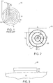
- Figure 1 shows a prior art concentric ring electrode 10 that includes a disc 12, an inner ring 14 a middle ring 16 and an outer ring 18.
- the thickness of each ring is the same (t) and the diameter of the disc 12 is 2t.
- the spacing between the disc and each of the rings (which includes a dielectric material 8) is also conventionally t .
- DE3025955 discloses a biomedical sensor that includes spring-biased protruding posts that appear to be electrically coupled to output wires.
- WO2008/005478 discloses concentric ring electrodes for brain stimulation. Further discussion of concentric ring electrodes is provided in Besio W G et al: "Comparison of bipolar vs. tripolar concentric ring electrode Laplacian estimates", Annual International Conference of the IEEE Engineering in Medicine and Biology - Proceedings - Conference Proceedings - 26th Annual International Conference of the IEEE Engineering in Medicine and Biology Society, EMBC 2004-2004 Institute of Electri, vol.
- an electrode gel e.g., an electrolyte
- an electrode gel has conventionally been used to bridge between electrodes and a cleaned surface of a subject (e.g., the scalp).
- the spacing required between electrodes may be so small that smearing of the electrolyte (and thus short circuiting of the bioelectric signal) may occur.
- the application and removal of electrolyte gels is an unpleasant process for the subject, and time consuming for the clinician or care giver.
- dry electrodes (not using a gel) have been introduced. With dry electrodes, however, movement artifacts are more prevalent due to the absence of a thick electrolyte layer (as is present in gels, which provides a shock absorber function).
- active electrodes where buffering/amplification takes place at the electrode site
- An added concern with dry electrodes is that the large RC constant, which exists at the input of the unity gain amplifiers typically used for this application, prolongs the effect of large artifacts.
- biomedical electrode according to claim 1.
- Preferred embodiments are defined in the dependent claims. Embodiments, examples and aspects disclosed herein but not falling under the scope of claim 1 do not form part of the invention.
- suitable electrodes should include an outer diameter of at least about 3.0 cm, and that the ratio of the center disc diameter to the outer ring thickness should be at least about four and less than about six, and preferably less than about five, with the ratio increasing for smaller diameter electrodes.
- the diameter of the inner ring d 1 should be t 2 multiplied by at least about four but less than about five (4 ⁇ d1 / t2 ⁇ 5).
- the electrode works well if the diameter of the center disc is 4.0 mm.
- the electrode works well when the center disc diameter is 2.0 mm. The improvements gained with this ratio for stimulation also allow for high-fidelity signal acquisition as well.
- FIG. 2 shows a quadra-polar biomedical electrode design in accordance with an embodiment of the invention.
- the biomedical electrode design 20 includes a center conductive ring 22, two concentric mid-conductive rings 24 and 26, and an outer concentric conductive ring 28.
- the inner ring has a diameter d 1 as shown
- the rings 24 and 26 have diameters of d 2 and d 3 as shown
- the outer ring has a diameter d 4 as shown.
- the conductive rings 24, 26 and 28 each have ring thickness t 2 , t 3 and t 4 as shown, and the diameters d 2 , d 3 and d 4 are measured to the outer edge of each of the conductor thicknesses.
- a dielectric material is provided in the spaces 21 between the disc and rings as shown.
- the conductive material used for the rings may include silver/silver chloride, gold, tin etc.
- the first ring 24 radius ( d 2 /2) was constrained to be greater than the radius of the central disc 22 ( d 1 /2) but less than the radius of the outermost ring 28 ( d 4 l 2) and the radius of the second ring 26 ( d 3 /2).
- the radius of the second ring 26 ( d 3 /2) was greater than the radius of the first ring 24 (d 1 /2) but less than the radius of the outer ring 28 ( d 4 /2).
- the above function yields 202,500 mm 4 , or 0.2025 cm 4 .
- the function yields less than about 0.225 cm 4 .
- the center disc diameter would be 2.0 mm.
- the radius at the center of the first ring could vary from 1.5 mm to 14 mm and the second ring radius at the center could vary from 2.5 mm to 14 mm.
- ⁇ must be small, e.g., 4.0 mm.
- Electrodes of the invention may be used for the acquisition of biopotentials in clinical and research applications.
- the new electrodes may be used for recording the electroencephalogram (EEG), electrocardiogram (ECG), electromyogram (EMG), electrooculogram (EOG) etc.
- EEG electroencephalogram
- ECG electrocardiogram
- EMG electromyogram
- EOG electrooculogram
- Use of the electrodes is also not limited to noninvasive recording; as they may also be used as implantable electrodes. They could also be used in any application where potentials need to be measured on a non-biological surface where movement artifact suppression is beneficial.
- Concentric electrodes take the differences of signals that are impressed on electrode elements very closely spaced (for EEG typically within 1.0 mm or less). The interference is nearly the same on both elements of the electrode and is automatically cancelled by common mode rejection. It may further be possible that electrodes of the invention are used in an application that permits or requires that a subject be mobile while monitoring their bio-potentials.
- a biomedical electrode of the invention may include conductive rings that themselves contact a patient's skin either with or without the use of a hydrogel.
- Figure 3 shows a side view of the biomedical electrode 20 as applied to a patient 32 using an electrolytic gel 30.
- different electrically conductive elements 22, 24, 26, 28
- the central disc 22 and the outermost ring 28 may be coupled together and to ground.
- electrodes of tri-polar biomedical electrodes of various embodiments may have the following dimensions as shown in Table 1 below.
- the electrode element areas are shown in Table 3 below.
- the disc has a diameter of 2.0mm, a disc radius of 1.0mm, a disc area of 3.14mm 2 , a first ring inner radius of 1.6mm, a first ring outer radius of 2.0mm, a first ring area of 4.52mm 2 , a second ring inner radius of 2.6mm, a second ring outer radius of 3.0mm, and a second ring area of 7.04mm 2 .
- the disc has a diameter of 2.8mm, a disc radius of 1.4mm, a disc area of 6.16mm 2 , a first ring inner radius of 2.6mm, a first ring outer radius of 3.2mm, a first ring area of 10.93mm 2 , a second ring inner radius of 4.4mm, a second ring outer radius of 5.0mm, and a second ring area of 17.72mm 2 .
- the disc has a diameter of 4.0mm, a disc radius of 2.0mm, a disc area of 12.57mm 2 , a first ring inner radius of 3.mm, a first ring outer radius of 4.0mm, a first ring area of 21.99mm 2 , a second ring inner radius of 7.0mm, a second ring outer radius of 8.0mm, and a second ring area of 47.12mm 2 .
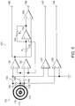
- Figure 5 shows a switching circuit system 100 for communicating with an electrode in accordance with an embodiment of the invention that provides for multiple outputs.
- the quad output concentric electrode 102 simultaneously provides two forms of unipolar, a bipolar output, as well as tripolar output using a series of switches 104, 106, and 108 that selectively couple the inner conductor 110, a middle conductor 112 and an outer conductor 114 to amplifiers 120, 122, 124 and 126 as shown.
- the system also includes switches 130 and 132 for selectively coupling the center conductor 110 to either the middle conductor 112 or the outer conductor 114 respectively or both.
- the amplifier 120 receives its positive input from the outer conductor 114 and its negative input from the center conductor 110, and the output of the amplifier 120 provides a bipolar output signal 140.
- the amplifier 124 receives its positive input from the outer conductor 114 and its negative input is coupled to ground.
- the output of the amplifier 124 provides an outer ring monopolar output signal 142 when the switch 132 is open and the switch 104 is closed.
- the amplifier 126 receives its positive input from the middle conductor 112 and 114 and its negative input is coupled to ground.
- the output of the amplifier 126 provides a switched monopolar output signal 144 when switches 130 and 132 are closed.
- Switches 104, 106 and 108 should be opened with the inputs to amplifiers 120, 122 and 124 connected to a reference or to a sample and hold circuit while, switches 130 and 132 are shorted.
- the amplifier 122 receives its positive input from the middle conductor 112 (via switch 108) and receives its negative input from the inner conductor 110 (via switch 106).
- the output of the amplifier 122 is provided to a positive input of a further amplifier 152 via a resistor 150 (R1 of e.g., 1 k Ohm) and the negative input of the amplifier 152 is coupled to the inner conductor 110.
- the output of the amplifier 152 is feedback coupled to the positive input through a resistor (R2 of e.g., 16 k Ohm) and is also coupled to the positive input of a further amplifier 156.
- the negative input of the amplifier 156 is coupled to the output of the amplifier 120, and the output of the amplifier 156 provides a tripolar output signal (16(M - D) - (O - D)).
- the outputs differ in spatial selectivity.
- This system produces a surface Laplacian output by taking the second radial spatial derivative of the surface signals and providing two forms of virtual unipolar output signals.
- the Laplacian operator is commonly performed in software to localize cortical activity since it approximates underlying cortical potentials from scalp voltage distributions.
- TCRE tripolar concentric ring electrodes
- the rationale for the proposed quad output concentric electrode is that it will maintain compatibility with existing EEG electrode methods, while also providing outputs with improved spatial localization of cortical activity.
- the spatial derivative outputs are self-referential, unlike unipolar electrodes, and are potentially less sensitive to most EEG artifacts. The above applies to EEG signals but is also appropriate for ECG, EMG, EOG, and other signal recordings.
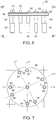
- FIG. 6 shows a biomedical electrode 50 in accordance with another embodiment of the invention.
- the biomedical electrode 50 in accordance with an embodiment includes a plurality of protruding electrodes 54 that extend through and protrude from a common base 56.
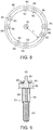
- Each electrode includes a fixed protruding portion 58 and a resilient protruding portion 60 that extends from the fixed protruding portion 58 as further shown in Figure 6 , which shows a bottom view.
- each electrode also includes a mounting post 62 that extends through the base 56.
- Each mounting post 62 is threaded, and a nut 64 is used to fasten each electrode onto the base 56 as further shown in Figure 9 .
- each protruding electrode may be attached to the base by a variety of known techniques, including for example, using solder, glue and/or press fit insertion.
- the protruding electrodes 54 may be connected to monitoring equipment in such a way that they remain electrically independent of one another, or in some embodiments, one or more groups of electrodes may be commonly coupled via conductors.
- Figure 8 shows a first outer conductor 66 that electrically join together the outer ring of electrodes.
- a second conductor may similarly electrically joins together an inner ring of electrodes.
- the innermost electrode is electrically independent of the others.
- Each conductor (e.g., 66) is coupled to its associated electrode 54 by being captured between the conductive fastening nut and the base 56 as shown in Figure 9 .
- Each electrode therefore, is electrically conductive from the post 62, through the fixed and resilient protrusion sections 58 and 60.
- each conductive ring may have any number of protruding electrodes.
- the inner ring may have one electrode
- the first ring may have six electrodes
- the second ring may have nine electrodes
- the third (outermost) ring may have nine electrodes.
- the electrodes may be positioned at a plurality of locations along the outer conductor. For example, four electrodes may be positioned along the X and Y axes as shown, and additional electrodes may be positioned that are rotationally displaced from the X and Y axes such as on the X' and Y' axes as shown.
- the spacing between electrodes coupled to a common conductor may vary as long as sufficient contact is made with the patient through the protruding electrodes 54.
- the fixed and resilient protruding portions may pass through the hair on a subject, and the biomedical sensors of the invention may be used either with or without a gel.
- the individual electrodes in accordance with an embodiment, are shaped of tubular rods such that the resilient protruding portion 60 penetrates through hair reaching the scalp of a subject.
- This force may be provided by a spring 69 in accordance with an embodiment.
- such a force may be provided by any of a variety of techniques such as the use of pneumatic or hydraulic pressure within the protruding electrodes 54.
- spring loaded electrical connector pins such as the long-stroke spring-loaded pin product (product number 0914), sold by Mill-Max Mfg. Corp. of Oyster Bay, New York may be used.
- Another benefit of making the biomedical sensor out of independent protruding electrodes is that the force will keep the individual electrodes contacting the scalp even if the scalp is not flat.
- the electrodes 60 will follow the contour of the scalp or other body part to which the electrode is applied.
- a conventional solid ring if there is a protrusion the ring may be raised up, not touching the scalp, altering the skin-to-electrode impedance. If a muscle contracts for example, protruding the skin upward below the surface of a conventional disc electrode, then part of the electrode may lose contact with the skin surface altering the skin-to-electrode impedance causing an artifact.
- Adding active electronics directly to the electrode matches the skin-to-electrode impedance better, permitting low impedance signals to be transmitted via wires to avoid AC power line interference.
- a conventional electrolytic gel may also be used to facilitate electrical conductivity with the subject.
- a gel may be applied through the resilient protruding portion in accordance with an embodiment.
- Connecting the electrodes together in such a way as to provide effective concentric ring electrodes and/or virtual concentric ring electrodes may be employed to achieve significantly better signal to noise ratios, spatial selectivity, approximation of the Laplacian, and mutual information, i.e., signals from areas of the subject that are outside of the target area of interest below the sensor.
- the virtual concentric electrodes would automatically attenuate distant sources such as eye blinks, jaw movements, ECG and ballistic ECG. Electrode preparation time will also be significantly improved.
- a skin-to-electrode paste is used.
- the paste has three functions: (1) matching skin-to-electrode impedance, (2) holding the electrode in place, and (3) acting as a shock absorber to lessen mechanical vibrations.
- a dense array of electrodes e.g., 64 or more
- a fabric type of electrode may be used.
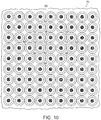
- an array of biomedical electrodes 70 may be provided in a fabric 98 of a garment 89 (shown in Figure 11 ) as fabric electrodes as shown in Figure 10 .
- the garment 89 also includes a support fabric 93 on the surface of the fabric electrodes opposite the subject contact surface 91 of the electrode as further shown in Figure 11 .
- the electrodes may be coupled to monitoring equipment via a connector 97 attached to the electrodes 70 via a connector cable 95.
- the fabric could be made of conductive yarns that take the shape of the electrodes. If the yarn has branches or protruding hairs the conductive yarns could help bridge through hair to connect the electrode to the scalp or skin. A liquid gel could also be applied to the fabric electrode that would help wet the hair and make contact with the scalp or skin. It is known that metallic conductors could be inverted into yarns to make the yarns conductive. It is also known that yarns may be soaked in carbon nanotube solutions to make the yarns conductive. Carbon foams, or other types of conductive foams, could also be used that would help bridge the gap and provide a shock absorber effect.
- Electrodes whether fabric or other composition, could be accomplished with electrically conductive tape, such as ARcare ® 8881 and ARcare ® 90366 adhesive products sold by Adhesives Research, Inc. of Glen Rock, Pennsylvania. This type of attachment may be advantageous for stabilizing the skin-to-electrode contact.
- the fabric 98 may, for example, include conductive yarns (e.g., as sold under the brand name NOVONIC by W.Zimmermann GmbH & Co. of Germany) that may be used for data transfer and/or power transfer (as well as textile-based heating).
- the conductive yarns may include a flexible core to ensure sufficient mechanical stability combined with high flexibility, wires that are shaped as a spiral to provide stretch resistance of the electrical conductor, and an outer textile to protect against overstretching and abrasion.
- the garment may include textile-based electrodes as disclosed, for example, in U.S. Patent No. 7,308,294 .
- the textile interface (97) may be a NOVONIC a textile interface between electronics and textiles, which provides integration of sensors and communication in washable textiles.
- the array of electrodes 70 includes biomedical electrodes 72, 74, 76, 78, 80, 82, 84, 86, 88, 90, 92, 94, 96 as disclosed in the above embodiments.
- the electrodes 72 - 96 each have a central disc and two concentric outer rings.
- a five point configuration may be employed using electrodes 72 ⁇ 80.
- electrode 72 provides a central node, while electrodes 74 ⁇ 80 provide a ring.
- V FPM V 72 ⁇ V 74 + V 72 ⁇ V 76 + V 72 ⁇ V 78 + V 72 ⁇ V 80
- V FPM is the estimate of the Laplacian at the center of the central electrode who's potential is V 72 and V 74 - V 80 are the potentials of electrodes 74 - 80 respectively.
- the potentials V 72 - V 80 would be the Laplacian estimates that are recorded from bipolar electrodes (outer ring potential - disc potential) or if using tripolar concentric ring electrodes V 72 - V 90 would each be 16*(middle ring potential - disc potential) - (outer ring potential - disc potential) for each of the 5 electrodes.
- V NPM 16 * V 74 ⁇ V 72 + V 76 ⁇ V 72 + V 78 ⁇ V 72 + V 80 ⁇ V 72 ⁇ V 82 ⁇ V 72 + V 84 ⁇ V 72 + V 86 ⁇ V 72 + V 88 ⁇ V 72
- V 72 ⁇ V 88 are either the bipolar or tripolar Laplacian potential estimates at electrodes 72 - 88.
- electrodes 72 - 88 could be of other configurations having more or less rings and using other Laplacian estimation algorithms.
- an array of electrodes could be used and stimulation could be targeted by using a subset of the electrodes such as electrodes 72 - 80 to reach a deeper central location than with just electrode 72.
- the electrodes 72 - 80 could be used to penetrate even deeper, and electrodes 72 - 96 to go deeper yet with less stimulation intensity on each electrode but covering a larger area.
- the stimulation depth and area stimulated may be adjusted by using similar configurations only the center virtual disc electrodes will form one concentric electrode element, such as 72, and the surrounding virtual disc electrodes will form the outer ring, such as 74 - 80.
- the stimulation depth, and volume of tissue can be adjusted by changing the diameter of the outer ring.
- the spatial resolution of where the stimulation is directed decreases inversely to the outer ring radius.
- stimulation can also be applied to the middle ring such as applying potential to a grid of a tube.
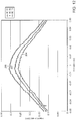
- Figure 12 shows the electric field profiles extracted across the x-axis of the model 49 mm into the brain generated from stimulation with the 20 mm diameter tri-polar concentric ring electrode.
- the magnitudes of the electric field ( ⁇ V/mm) produced from stimulation with the 20 mm diameter tri-polar electrode at different depths in the brain layer of the model along the z-axis are presented in Table 4.
- the values other than those for the 77 mm (center) are of sufficient magnitude to provide neuronal modulation.
- Table 4 Input Stimulus (mA) (Outer/Middle) 10 mm 20 mm 30 mm 40 mm 77 mm (center) 90/60 5467 2002 938 489 90 90/30 4937 1813 851 443 82 90/10 4504 1687 792 413 76
Landscapes
- Health & Medical Sciences (AREA)
- Life Sciences & Earth Sciences (AREA)
- Public Health (AREA)
- Engineering & Computer Science (AREA)
- Biomedical Technology (AREA)
- Veterinary Medicine (AREA)
- Animal Behavior & Ethology (AREA)
- General Health & Medical Sciences (AREA)
- Radiology & Medical Imaging (AREA)
- Nuclear Medicine, Radiotherapy & Molecular Imaging (AREA)
- Heart & Thoracic Surgery (AREA)
- Physics & Mathematics (AREA)
- Biophysics (AREA)
- Pathology (AREA)
- Medical Informatics (AREA)
- Molecular Biology (AREA)
- Surgery (AREA)
- Cardiology (AREA)
- Measurement And Recording Of Electrical Phenomena And Electrical Characteristics Of The Living Body (AREA)
Applications Claiming Priority (2)
| Application Number | Priority Date | Filing Date | Title |
|---|---|---|---|
| US25563509P | 2009-10-28 | 2009-10-28 | |
| PCT/US2010/054211 WO2011056626A1 (en) | 2009-10-28 | 2010-10-27 | Biomedical electrode |
Publications (2)
| Publication Number | Publication Date |
|---|---|
| EP2493374A1 EP2493374A1 (en) | 2012-09-05 |
| EP2493374B1 true EP2493374B1 (en) | 2016-12-14 |
Family
ID=43402174
Family Applications (1)
| Application Number | Title | Priority Date | Filing Date |
|---|---|---|---|
| EP10773801.5A Active EP2493374B1 (en) | 2009-10-28 | 2010-10-27 | Biomedical electrode |
Country Status (6)
Cited By (1)
| Publication number | Priority date | Publication date | Assignee | Title |
|---|---|---|---|---|
| WO2020016785A1 (es) | 2018-07-16 | 2020-01-23 | Panacea Quantum Leap Technology Llc | Electrodos de placas |
Families Citing this family (88)
| Publication number | Priority date | Publication date | Assignee | Title |
|---|---|---|---|---|
| US9351659B2 (en) * | 2009-07-28 | 2016-05-31 | Altec, Inc. | Biomedical electrode configuration for suppressing movement artifact |
| CN102762251B (zh) | 2009-10-02 | 2015-02-11 | 麦德托尼克艾克斯欧麦德股份有限公司 | 气管内导管设备 |
| JP2013509251A (ja) * | 2009-10-28 | 2013-03-14 | ボード オブ ガバナーズ フォー ハイヤー エデュケーション, ステート オブ ロード アイランド アンド プロヴィデンス プランテーションズ | 生体用電極 |
| KR100965351B1 (ko) * | 2009-11-23 | 2010-06-22 | 박문서 | 인체내 임피던스 측정을 위한 전극 장치를 이용한 인체내 임피던스 측정과 시술 장치 |
| US9529689B2 (en) | 2009-11-30 | 2016-12-27 | Red Hat, Inc. | Monitoring cloud computing environments |
| EP2569618B1 (en) | 2010-05-08 | 2017-03-01 | The Regents of the University of California | Sem scanner sensing apparatus, system and methodology for early detection of ulcers |
| US20120041332A1 (en) * | 2010-08-11 | 2012-02-16 | Georgiy Lifshits | Device and method for oriental medicine diagnosis and treatment |
| US20130338529A1 (en) * | 2011-02-28 | 2013-12-19 | Nihon Kohden Corporation | Bioelectric signal measurement apparatus |
| TWI446896B (zh) * | 2011-12-23 | 2014-08-01 | Ind Tech Res Inst | 肌能參數感測器 |
| US9931079B2 (en) | 2012-01-04 | 2018-04-03 | Medtronic Xomed, Inc. | Clamp for securing a terminal end of a wire to a surface electrode |
| ES2856873T3 (es) | 2012-02-06 | 2021-09-28 | Childrens Medical Center | Biomaterial multicapa para la regeneración de tejidos y la cicatrización de las heridas |
| GB2499406A (en) * | 2012-02-15 | 2013-08-21 | Michael Corbett | Fabric electrode modules |
| ES2425692B2 (es) * | 2012-03-13 | 2014-12-04 | Universidad Politécnica De Valencia | Aparato de medida de señales bioelectricas en superficie corporal basado en sensores anulares ajustables |
| US8977335B2 (en) | 2012-03-29 | 2015-03-10 | Ad-Tech Medical Instrument Corp. | Intracranial sensing and monitoring device with macro and micro electrodes |
| EP2882335A4 (en) * | 2012-08-09 | 2016-04-06 | Univ Northeastern | ELECTROFIELD ENZEPHALOGRAPHY: ELECTROFIELD-BASED BRAIN SIGNAL DETECTION AND MONITORING |
| US10159440B2 (en) | 2014-03-10 | 2018-12-25 | L.I.F.E. Corporation S.A. | Physiological monitoring garments |
| US11246213B2 (en) | 2012-09-11 | 2022-02-08 | L.I.F.E. Corporation S.A. | Physiological monitoring garments |
| US8945328B2 (en) | 2012-09-11 | 2015-02-03 | L.I.F.E. Corporation S.A. | Methods of making garments having stretchable and conductive ink |
| US9817440B2 (en) | 2012-09-11 | 2017-11-14 | L.I.F.E. Corporation S.A. | Garments having stretchable and conductive ink |
| US9282893B2 (en) | 2012-09-11 | 2016-03-15 | L.I.F.E. Corporation S.A. | Wearable communication platform |
| US10462898B2 (en) | 2012-09-11 | 2019-10-29 | L.I.F.E. Corporation S.A. | Physiological monitoring garments |
| US10201310B2 (en) | 2012-09-11 | 2019-02-12 | L.I.F.E. Corporation S.A. | Calibration packaging apparatuses for physiological monitoring garments |
| US8948839B1 (en) | 2013-08-06 | 2015-02-03 | L.I.F.E. Corporation S.A. | Compression garments having stretchable and conductive ink |
| US9060744B2 (en) | 2012-11-29 | 2015-06-23 | Medtronic Xomed, Inc. | Endobronchial tube apparatus |
| US9913594B2 (en) | 2013-03-14 | 2018-03-13 | Medtronic Xomed, Inc. | Compliant electrode for EMG endotracheal tube |
| US9808170B2 (en) * | 2013-03-15 | 2017-11-07 | Welch Allyn, Inc. | Electrode with charge-operated indicator |
| US10912480B2 (en) | 2013-06-21 | 2021-02-09 | Northeastern University | Sensor system and process for measuring electric activity of the brain, including electric field encephalography |
| US9445740B1 (en) | 2013-06-28 | 2016-09-20 | West Affum Holdings Corp. | Patient signal sensing device |
| US20150025352A1 (en) * | 2013-07-22 | 2015-01-22 | NorDocs Technologies Inc. | Method and device for determining brain and scalp state |
| CN104414635A (zh) * | 2013-09-04 | 2015-03-18 | 上海帝仪科技有限公司 | 干电极及其制造方法 |
| US9295403B1 (en) * | 2013-12-19 | 2016-03-29 | Verily Life Sciences Llc | Multipurpose wearable electrical contact |
| WO2015103620A1 (en) | 2014-01-06 | 2015-07-09 | Andrea Aliverti | Systems and methods to automatically determine garment fit |
| WO2015179379A1 (en) * | 2014-05-19 | 2015-11-26 | Anthrotronix, Inc. | Electrodermal interface system |
| CN104224173B (zh) * | 2014-09-23 | 2018-07-17 | 思澜科技(成都)有限公司 | 用于电阻抗断层成像的电极检测工装 |
| US10123718B2 (en) * | 2014-10-30 | 2018-11-13 | University Of Tenessee Research Foundation | Methods, systems, and assemblies for measuring bioelectrical signals of intra-abdominal organs |
| TW201625330A (zh) * | 2015-01-08 | 2016-07-16 | 國立陽明大學 | 同心圓矽膠電極及其電刺激系統 |
| CN104757971B (zh) * | 2015-04-15 | 2017-01-25 | 重庆博恩富克医疗设备有限公司 | 一种信号检测装置及方法 |
| WO2016172263A1 (en) | 2015-04-24 | 2016-10-27 | Bruin Biometrics Llc | Apparatus and methods for determining damaged tissue using sub-epidermal moisture measurements |
| KR102593337B1 (ko) | 2015-07-20 | 2023-10-23 | 엘.아이.에프.이. 코포레이션 에스.에이. | 센서들 및 전자장치를 가진 의류용 유연한 패브릭 리본 연결기들 |
| GB2541947A (en) * | 2015-09-07 | 2017-03-08 | Cerestim Ltd | Electrode apparatus |
| JP6746300B2 (ja) | 2015-11-30 | 2020-08-26 | 株式会社リコー | 神経刺激装置、生体磁界計測システム |
| EP3478174A1 (en) | 2016-07-01 | 2019-05-08 | L.I.F.E. Corporation S.A. | Biometric identification by garments having a plurality of sensors |
| CN118177725A (zh) | 2017-02-03 | 2024-06-14 | 布鲁恩医疗创新有限责任公司 | 糖尿病足溃疡易感性的测量 |
| EP3515298A4 (en) | 2017-02-03 | 2020-03-11 | Bruin Biometrics, LLC | MEASUREMENT OF EDEMA |
| PL3515296T3 (pl) | 2017-02-03 | 2024-03-25 | Bbi Medical Innovations, Llc | Pomiar żywotności tkanki |
| US11096626B2 (en) * | 2017-05-22 | 2021-08-24 | Maurice-Andre Recanati | Fetal scalp monitor |
| US10420505B2 (en) * | 2017-07-18 | 2019-09-24 | Forest Devices, Inc. | Electrode array apparatus, neurological condition detection apparatus, and method of using the same |
| AU2018322472A1 (en) | 2017-08-22 | 2020-04-02 | Medtronic Xomed, Inc. | System and method for evoking a reflex to monitor the nerves of the larynx |
| US11110240B2 (en) | 2017-09-07 | 2021-09-07 | Medtronic Xomed, Inc. | Endotracheal tube with tube coating |
| JP7209713B2 (ja) | 2017-11-16 | 2023-01-20 | ブルーイン、バイオメトリクス、リミテッド、ライアビリティー、カンパニー | 表皮下水分値を用いた褥瘡性潰瘍の戦略的処置 |
| PT3749181T (pt) | 2018-02-09 | 2024-05-15 | Bruin Biometrics Llc | Deteção de lesões nos tecidos |
| US11160972B2 (en) | 2018-03-30 | 2021-11-02 | Zoll Medical Corporation | Garments for wearable cardiac monitoring and treatment devices |
| US10340408B1 (en) | 2018-05-17 | 2019-07-02 | Hi Llc | Non-invasive wearable brain interface systems including a headgear and a plurality of self-contained photodetector units configured to removably attach to the headgear |
| US10420498B1 (en) | 2018-06-20 | 2019-09-24 | Hi Llc | Spatial and temporal-based diffusive correlation spectroscopy systems and methods |
| US11213206B2 (en) | 2018-07-17 | 2022-01-04 | Hi Llc | Non-invasive measurement systems with single-photon counting camera |
| IL290883B2 (en) | 2018-10-11 | 2024-02-01 | Bruin Biometrics Llc | Device with disposable element |
| TW202041205A (zh) * | 2018-12-26 | 2020-11-16 | 愛爾蘭商博士健康愛爾蘭有限公司 | 用於經皮能量輸送之可撓性電路施用器 |
| WO2020226840A1 (en) | 2019-05-06 | 2020-11-12 | Hi Llc | Photodetector architectures for time-correlated single photon counting |
| US12144630B2 (en) | 2019-05-20 | 2024-11-19 | Diné College | Determination of optimal Laplacian estimates and optimal inter-ring distances for concentric ring electrodes |
| WO2020247185A1 (en) | 2019-06-06 | 2020-12-10 | Hi Llc | Photodetector systems with low-power time-to-digital converter architectures |
| WO2021071871A1 (en) * | 2019-10-09 | 2021-04-15 | Trustees Of Boston University | Electrography system employing layered electrodes for improved spatial resolution |
| EP4081121A4 (en) | 2019-12-23 | 2024-01-03 | Alimetry Limited | Electrode patch and connection system |
| WO2021167877A1 (en) | 2020-02-21 | 2021-08-26 | Hi Llc | Multimodal wearable measurement systems and methods |
| US12144653B2 (en) | 2020-02-21 | 2024-11-19 | Hi Llc | Systems, circuits, and methods for reducing common-mode noise in biopotential recordings |
| US11950879B2 (en) | 2020-02-21 | 2024-04-09 | Hi Llc | Estimation of source-detector separation in an optical measurement system |
| US11969259B2 (en) | 2020-02-21 | 2024-04-30 | Hi Llc | Detector assemblies for a wearable module of an optical measurement system and including spring-loaded light-receiving members |
| US12029558B2 (en) | 2020-02-21 | 2024-07-09 | Hi Llc | Time domain-based optical measurement systems and methods configured to measure absolute properties of tissue |
| US11771362B2 (en) | 2020-02-21 | 2023-10-03 | Hi Llc | Integrated detector assemblies for a wearable module of an optical measurement system |
| US11515014B2 (en) | 2020-02-21 | 2022-11-29 | Hi Llc | Methods and systems for initiating and conducting a customized computer-enabled brain research study |
| WO2021167892A1 (en) | 2020-02-21 | 2021-08-26 | Hi Llc | Wearable devices and wearable assemblies with adjustable positioning for use in an optical measurement system |
| US11903676B2 (en) | 2020-03-20 | 2024-02-20 | Hi Llc | Photodetector calibration of an optical measurement system |
| US11877825B2 (en) | 2020-03-20 | 2024-01-23 | Hi Llc | Device enumeration in an optical measurement system |
| WO2021188486A1 (en) | 2020-03-20 | 2021-09-23 | Hi Llc | Phase lock loop circuit based adjustment of a measurement time window in an optical measurement system |
| US11245404B2 (en) | 2020-03-20 | 2022-02-08 | Hi Llc | Phase lock loop circuit based signal generation in an optical measurement system |
| US11857348B2 (en) | 2020-03-20 | 2024-01-02 | Hi Llc | Techniques for determining a timing uncertainty of a component of an optical measurement system |
| US11187575B2 (en) | 2020-03-20 | 2021-11-30 | Hi Llc | High density optical measurement systems with minimal number of light sources |
| WO2021188488A1 (en) | 2020-03-20 | 2021-09-23 | Hi Llc | Bias voltage generation in an optical measurement system |
| US12138068B2 (en) | 2020-03-20 | 2024-11-12 | Hi Llc | Techniques for characterizing a nonlinearity of a time-to-digital converter in an optical measurement system |
| WO2021188487A1 (en) | 2020-03-20 | 2021-09-23 | Hi Llc | Temporal resolution control for temporal point spread function generation in an optical measurement system |
| WO2021188485A1 (en) | 2020-03-20 | 2021-09-23 | Hi Llc | Maintaining consistent photodetector sensitivity in an optical measurement system |
| US12059262B2 (en) | 2020-03-20 | 2024-08-13 | Hi Llc | Maintaining consistent photodetector sensitivity in an optical measurement system |
| US11864867B2 (en) | 2020-03-20 | 2024-01-09 | Hi Llc | Control circuit for a light source in an optical measurement system by applying voltage with a first polarity to start an emission of a light pulse and applying voltage with a second polarity to stop the emission of the light pulse |
| US12059270B2 (en) | 2020-04-24 | 2024-08-13 | Hi Llc | Systems and methods for noise removal in an optical measurement system |
| US20220054032A1 (en) * | 2020-08-21 | 2022-02-24 | Chimei Medical Center | Method for enhancing local eeg signals and eeg electrode device |
| US11045132B1 (en) | 2020-10-09 | 2021-06-29 | Diné College | Concentric ring electrodes for improved accuracy of Laplacian estimation |
| TW202227015A (zh) * | 2021-01-04 | 2022-07-16 | 國立中央大學 | 腦波乾式電極 |
| US11642075B2 (en) | 2021-02-03 | 2023-05-09 | Bruin Biometrics, Llc | Methods of treating deep and early-stage pressure induced tissue damage |
| CN114870247B (zh) * | 2022-04-26 | 2025-06-13 | 上海交通大学医学院附属第九人民医院 | 一种用于耳蜗核精准刺激的拟神经电极 |
Family Cites Families (17)
| Publication number | Priority date | Publication date | Assignee | Title |
|---|---|---|---|---|
| DE3025955A1 (de) * | 1980-07-09 | 1982-01-21 | Forschungsgesellschaft für Biomedizinische Technik, 5100 Aachen | Ableitelektrode zur aufnahme bioelektrischer aktivitaet von behaarten koerperregionen |
| EP0346513A1 (de) * | 1988-06-15 | 1989-12-20 | Etama Ag | Anordnung zur Elektrotherapie |
| US5111812A (en) * | 1990-01-23 | 1992-05-12 | Cardiac Pacemakers, Inc. | Defilbrillation electrode having smooth current distribution |
| US6073039A (en) * | 1997-11-07 | 2000-06-06 | The United States Of America As Represented By The Department Of Health And Human Services | Device and method for real-time monitoring of an electrocardiogram during magnetic resonance imaging |
| US7146217B2 (en) * | 2000-07-13 | 2006-12-05 | Northstar Neuroscience, Inc. | Methods and apparatus for effectuating a change in a neural-function of a patient |
| US20030125786A1 (en) | 2000-07-13 | 2003-07-03 | Gliner Bradford Evan | Methods and apparatus for effectuating a lasting change in a neural-function of a patient |
| US7305268B2 (en) * | 2000-07-13 | 2007-12-04 | Northstar Neurscience, Inc. | Systems and methods for automatically optimizing stimulus parameters and electrode configurations for neuro-stimulators |
| AU2002258565A1 (en) * | 2001-03-20 | 2002-10-03 | Bruce R. Gilbert, M.D., Ph.D., P.C. | Device for surface stimulation of acupuncture points |
| EP1427332A1 (en) * | 2001-08-24 | 2004-06-16 | Glucosens, Inc. | Biological signal sensor and device for recording biological signals incorporating the said sensor |
| GB2418365B (en) | 2001-09-07 | 2006-06-14 | Desmond Bryan Mills | Contact electrode |
| JP2005510312A (ja) * | 2001-11-29 | 2005-04-21 | インパルス ダイナミックス エヌブイ | 膵臓の電気的活動度を検出する方法及び装置 |
| US7998080B2 (en) * | 2002-01-15 | 2011-08-16 | Orsan Medical Technologies Ltd. | Method for monitoring blood flow to brain |
| KR100459903B1 (ko) * | 2002-07-25 | 2004-12-03 | 삼성전자주식회사 | 피부의 국부적인 영역의 임피던스를 측정하는 측정 시스템및 이에 이용되는 임피던스 측정 전극 |
| US8190248B2 (en) | 2003-10-16 | 2012-05-29 | Louisiana Tech University Foundation, Inc. | Medical devices for the detection, prevention and/or treatment of neurological disorders, and methods related thereto |
| US7308294B2 (en) | 2005-03-16 | 2007-12-11 | Textronics Inc. | Textile-based electrode system |
| EP2038004B1 (en) * | 2006-07-05 | 2018-01-24 | Precisis AG | System for treatment of neurological disorders via electrical stimulation |
| JP2013509251A (ja) * | 2009-10-28 | 2013-03-14 | ボード オブ ガバナーズ フォー ハイヤー エデュケーション, ステート オブ ロード アイランド アンド プロヴィデンス プランテーションズ | 生体用電極 |
-
2010
- 2010-10-27 JP JP2012536980A patent/JP2013509251A/ja active Pending
- 2010-10-27 CA CA2777126A patent/CA2777126C/en active Active
- 2010-10-27 AU AU2010315490A patent/AU2010315490B2/en active Active
- 2010-10-27 WO PCT/US2010/054211 patent/WO2011056626A1/en active Application Filing
- 2010-10-27 EP EP10773801.5A patent/EP2493374B1/en active Active
-
2012
- 2012-01-30 US US13/361,452 patent/US8352012B2/en active Active
- 2012-11-30 US US13/690,077 patent/US8615283B2/en active Active
Cited By (4)
| Publication number | Priority date | Publication date | Assignee | Title |
|---|---|---|---|---|
| WO2020016785A1 (es) | 2018-07-16 | 2020-01-23 | Panacea Quantum Leap Technology Llc | Electrodos de placas |
| EP3824944A4 (en) * | 2018-07-16 | 2022-04-20 | Panacea Quantum Leap Technology LLC | PLATE ELECTRODES |
| IL280185B1 (en) * | 2018-07-16 | 2024-11-01 | Panacea Quantum Leap Tech Llc | Plate electrodes |
| IL280185B2 (en) * | 2018-07-16 | 2025-03-01 | Panacea Quantum Leap Tech Llc | Plate electrodes |
Also Published As
| Publication number | Publication date |
|---|---|
| US20130079860A1 (en) | 2013-03-28 |
| WO2011056626A1 (en) | 2011-05-12 |
| EP2493374A1 (en) | 2012-09-05 |
| US20120150011A1 (en) | 2012-06-14 |
| AU2010315490B2 (en) | 2015-02-12 |
| US8615283B2 (en) | 2013-12-24 |
| US8352012B2 (en) | 2013-01-08 |
| JP2013509251A (ja) | 2013-03-14 |
| AU2010315490A1 (en) | 2012-04-26 |
| CA2777126C (en) | 2020-08-25 |
| CA2777126A1 (en) | 2011-05-12 |
Similar Documents
| Publication | Publication Date | Title |
|---|---|---|
| EP2493374B1 (en) | Biomedical electrode | |
| US8626259B2 (en) | Biomedical sensors usable on un-prepared contact surfaces | |
| Thakor | Biopotentials and electrophysiology measurement | |
| Jochum et al. | Integrated circuit amplifiers for multi-electrode intracortical recording | |
| EP2394571B1 (en) | Apparatus and method for measuring a biological signal | |
| Nishimura et al. | Clinical application of an active electrode using an operational amplifier | |
| US20240090814A1 (en) | Rapid manufacturing of absorbent substrates for soft, conformable sensors and conductors | |
| CN103239221B (zh) | 测量生物电势的电极及其制造方法和测量生理信号的系统 | |
| US20150238100A1 (en) | Sensor electrode device | |
| Prats-Boluda et al. | Active flexible concentric ring electrode for non-invasive surface bioelectrical recordings | |
| Vlach et al. | Capacitive biopotential electrode with a ceramic dielectric layer | |
| Akinin et al. | Biopotential measurements and electrodes | |
| WO2018071915A1 (en) | Concurrent transmitting and receiving electroencephalograph electrodes | |
| Lacirignola et al. | Hardware design of a wearable ECG-sensor: Strategies implementation for improving CMRR and reducing noise | |
| Ianov et al. | Development of a capacitive coupling electrode for bioelectrical signal measurements and assistive device use | |
| US20140142458A1 (en) | Implantable monitoring device with selectable reference channel and optimized electrode placement | |
| Vuorinen et al. | Printed, skin-mounted hybrid system for ECG measurements | |
| Terkildsen et al. | The influence of reference electrode position on recordings of the auditory brainstem responses | |
| Towe | Bioelectricity and its measurement | |
| Fauzani et al. | Two electrodes system: Performance on ECG FECG and EMG detection | |
| WO2012088329A2 (en) | Dry gel-conductive scaffold sensor | |
| López et al. | Reference electrode placement in EOG-based systems design | |
| Hazrati et al. | Wireless brain signal recordings based on capacitive electrodes | |
| US20230309888A1 (en) | Apparatus and method for hybrid biosensors | |
| EP3851047A1 (en) | Improved wireless electrocardiograph |
Legal Events
| Date | Code | Title | Description |
|---|---|---|---|
| PUAI | Public reference made under article 153(3) epc to a published international application that has entered the european phase |
Free format text: ORIGINAL CODE: 0009012 |
|
| 17P | Request for examination filed |
Effective date: 20120330 |
|
| AK | Designated contracting states |
Kind code of ref document: A1 Designated state(s): AL AT BE BG CH CY CZ DE DK EE ES FI FR GB GR HR HU IE IS IT LI LT LU LV MC MK MT NL NO PL PT RO RS SE SI SK SM TR |
|
| DAX | Request for extension of the european patent (deleted) | ||
| 17Q | First examination report despatched |
Effective date: 20150401 |
|
| REG | Reference to a national code |
Ref country code: DE Ref legal event code: R079 Ref document number: 602010038825 Country of ref document: DE Free format text: PREVIOUS MAIN CLASS: A61B0005040800 Ipc: A61B0005047800 |
|
| GRAP | Despatch of communication of intention to grant a patent |
Free format text: ORIGINAL CODE: EPIDOSNIGR1 |
|
| RIC1 | Information provided on ipc code assigned before grant |
Ipc: A61B 5/0478 20060101AFI20160512BHEP Ipc: A61N 1/04 20060101ALI20160512BHEP Ipc: A61B 5/04 20060101ALI20160512BHEP |
|
| INTG | Intention to grant announced |
Effective date: 20160607 |
|
| GRAS | Grant fee paid |
Free format text: ORIGINAL CODE: EPIDOSNIGR3 |
|
| GRAA | (expected) grant |
Free format text: ORIGINAL CODE: 0009210 |
|
| AK | Designated contracting states |
Kind code of ref document: B1 Designated state(s): AL AT BE BG CH CY CZ DE DK EE ES FI FR GB GR HR HU IE IS IT LI LT LU LV MC MK MT NL NO PL PT RO RS SE SI SK SM TR |
|
| REG | Reference to a national code |
Ref country code: GB Ref legal event code: FG4D |
|
| REG | Reference to a national code |
Ref country code: CH Ref legal event code: EP |
|
| REG | Reference to a national code |
Ref country code: IE Ref legal event code: FG4D |
|
| REG | Reference to a national code |
Ref country code: AT Ref legal event code: REF Ref document number: 852828 Country of ref document: AT Kind code of ref document: T Effective date: 20170115 |
|
| REG | Reference to a national code |
Ref country code: DE Ref legal event code: R096 Ref document number: 602010038825 Country of ref document: DE |
|
| PG25 | Lapsed in a contracting state [announced via postgrant information from national office to epo] |
Ref country code: LV Free format text: LAPSE BECAUSE OF FAILURE TO SUBMIT A TRANSLATION OF THE DESCRIPTION OR TO PAY THE FEE WITHIN THE PRESCRIBED TIME-LIMIT Effective date: 20161214 |
|
| REG | Reference to a national code |
Ref country code: LT Ref legal event code: MG4D |
|
| REG | Reference to a national code |
Ref country code: NL Ref legal event code: MP Effective date: 20161214 |
|
| PG25 | Lapsed in a contracting state [announced via postgrant information from national office to epo] |
Ref country code: NO Free format text: LAPSE BECAUSE OF FAILURE TO SUBMIT A TRANSLATION OF THE DESCRIPTION OR TO PAY THE FEE WITHIN THE PRESCRIBED TIME-LIMIT Effective date: 20170314 Ref country code: SE Free format text: LAPSE BECAUSE OF FAILURE TO SUBMIT A TRANSLATION OF THE DESCRIPTION OR TO PAY THE FEE WITHIN THE PRESCRIBED TIME-LIMIT Effective date: 20161214 Ref country code: GR Free format text: LAPSE BECAUSE OF FAILURE TO SUBMIT A TRANSLATION OF THE DESCRIPTION OR TO PAY THE FEE WITHIN THE PRESCRIBED TIME-LIMIT Effective date: 20170315 Ref country code: LT Free format text: LAPSE BECAUSE OF FAILURE TO SUBMIT A TRANSLATION OF THE DESCRIPTION OR TO PAY THE FEE WITHIN THE PRESCRIBED TIME-LIMIT Effective date: 20161214 |
|
| REG | Reference to a national code |
Ref country code: AT Ref legal event code: MK05 Ref document number: 852828 Country of ref document: AT Kind code of ref document: T Effective date: 20161214 |
|
| PG25 | Lapsed in a contracting state [announced via postgrant information from national office to epo] |
Ref country code: HR Free format text: LAPSE BECAUSE OF FAILURE TO SUBMIT A TRANSLATION OF THE DESCRIPTION OR TO PAY THE FEE WITHIN THE PRESCRIBED TIME-LIMIT Effective date: 20161214 Ref country code: FI Free format text: LAPSE BECAUSE OF FAILURE TO SUBMIT A TRANSLATION OF THE DESCRIPTION OR TO PAY THE FEE WITHIN THE PRESCRIBED TIME-LIMIT Effective date: 20161214 Ref country code: RS Free format text: LAPSE BECAUSE OF FAILURE TO SUBMIT A TRANSLATION OF THE DESCRIPTION OR TO PAY THE FEE WITHIN THE PRESCRIBED TIME-LIMIT Effective date: 20161214 |
|
| PG25 | Lapsed in a contracting state [announced via postgrant information from national office to epo] |
Ref country code: NL Free format text: LAPSE BECAUSE OF FAILURE TO SUBMIT A TRANSLATION OF THE DESCRIPTION OR TO PAY THE FEE WITHIN THE PRESCRIBED TIME-LIMIT Effective date: 20161214 |
|
| PG25 | Lapsed in a contracting state [announced via postgrant information from national office to epo] |
Ref country code: CZ Free format text: LAPSE BECAUSE OF FAILURE TO SUBMIT A TRANSLATION OF THE DESCRIPTION OR TO PAY THE FEE WITHIN THE PRESCRIBED TIME-LIMIT Effective date: 20161214 Ref country code: EE Free format text: LAPSE BECAUSE OF FAILURE TO SUBMIT A TRANSLATION OF THE DESCRIPTION OR TO PAY THE FEE WITHIN THE PRESCRIBED TIME-LIMIT Effective date: 20161214 Ref country code: RO Free format text: LAPSE BECAUSE OF FAILURE TO SUBMIT A TRANSLATION OF THE DESCRIPTION OR TO PAY THE FEE WITHIN THE PRESCRIBED TIME-LIMIT Effective date: 20161214 Ref country code: IS Free format text: LAPSE BECAUSE OF FAILURE TO SUBMIT A TRANSLATION OF THE DESCRIPTION OR TO PAY THE FEE WITHIN THE PRESCRIBED TIME-LIMIT Effective date: 20170414 Ref country code: SK Free format text: LAPSE BECAUSE OF FAILURE TO SUBMIT A TRANSLATION OF THE DESCRIPTION OR TO PAY THE FEE WITHIN THE PRESCRIBED TIME-LIMIT Effective date: 20161214 |
|
| PG25 | Lapsed in a contracting state [announced via postgrant information from national office to epo] |
Ref country code: BE Free format text: LAPSE BECAUSE OF FAILURE TO SUBMIT A TRANSLATION OF THE DESCRIPTION OR TO PAY THE FEE WITHIN THE PRESCRIBED TIME-LIMIT Effective date: 20161214 Ref country code: ES Free format text: LAPSE BECAUSE OF FAILURE TO SUBMIT A TRANSLATION OF THE DESCRIPTION OR TO PAY THE FEE WITHIN THE PRESCRIBED TIME-LIMIT Effective date: 20161214 Ref country code: AT Free format text: LAPSE BECAUSE OF FAILURE TO SUBMIT A TRANSLATION OF THE DESCRIPTION OR TO PAY THE FEE WITHIN THE PRESCRIBED TIME-LIMIT Effective date: 20161214 Ref country code: IT Free format text: LAPSE BECAUSE OF FAILURE TO SUBMIT A TRANSLATION OF THE DESCRIPTION OR TO PAY THE FEE WITHIN THE PRESCRIBED TIME-LIMIT Effective date: 20161214 Ref country code: BG Free format text: LAPSE BECAUSE OF FAILURE TO SUBMIT A TRANSLATION OF THE DESCRIPTION OR TO PAY THE FEE WITHIN THE PRESCRIBED TIME-LIMIT Effective date: 20170314 Ref country code: PT Free format text: LAPSE BECAUSE OF FAILURE TO SUBMIT A TRANSLATION OF THE DESCRIPTION OR TO PAY THE FEE WITHIN THE PRESCRIBED TIME-LIMIT Effective date: 20170414 Ref country code: PL Free format text: LAPSE BECAUSE OF FAILURE TO SUBMIT A TRANSLATION OF THE DESCRIPTION OR TO PAY THE FEE WITHIN THE PRESCRIBED TIME-LIMIT Effective date: 20161214 Ref country code: SM Free format text: LAPSE BECAUSE OF FAILURE TO SUBMIT A TRANSLATION OF THE DESCRIPTION OR TO PAY THE FEE WITHIN THE PRESCRIBED TIME-LIMIT Effective date: 20161214 |
|
| REG | Reference to a national code |
Ref country code: DE Ref legal event code: R097 Ref document number: 602010038825 Country of ref document: DE |
|
| PLBE | No opposition filed within time limit |
Free format text: ORIGINAL CODE: 0009261 |
|
| STAA | Information on the status of an ep patent application or granted ep patent |
Free format text: STATUS: NO OPPOSITION FILED WITHIN TIME LIMIT |
|
| REG | Reference to a national code |
Ref country code: FR Ref legal event code: PLFP Year of fee payment: 8 |
|
| 26N | No opposition filed |
Effective date: 20170915 |
|
| PG25 | Lapsed in a contracting state [announced via postgrant information from national office to epo] |
Ref country code: DK Free format text: LAPSE BECAUSE OF FAILURE TO SUBMIT A TRANSLATION OF THE DESCRIPTION OR TO PAY THE FEE WITHIN THE PRESCRIBED TIME-LIMIT Effective date: 20161214 |
|
| PG25 | Lapsed in a contracting state [announced via postgrant information from national office to epo] |
Ref country code: SI Free format text: LAPSE BECAUSE OF FAILURE TO SUBMIT A TRANSLATION OF THE DESCRIPTION OR TO PAY THE FEE WITHIN THE PRESCRIBED TIME-LIMIT Effective date: 20161214 |
|
| PG25 | Lapsed in a contracting state [announced via postgrant information from national office to epo] |
Ref country code: MC Free format text: LAPSE BECAUSE OF FAILURE TO SUBMIT A TRANSLATION OF THE DESCRIPTION OR TO PAY THE FEE WITHIN THE PRESCRIBED TIME-LIMIT Effective date: 20161214 |
|
| REG | Reference to a national code |
Ref country code: CH Ref legal event code: PL |
|
| REG | Reference to a national code |
Ref country code: IE Ref legal event code: MM4A |
|
| PG25 | Lapsed in a contracting state [announced via postgrant information from national office to epo] |
Ref country code: LI Free format text: LAPSE BECAUSE OF NON-PAYMENT OF DUE FEES Effective date: 20171031 Ref country code: CH Free format text: LAPSE BECAUSE OF NON-PAYMENT OF DUE FEES Effective date: 20171031 Ref country code: LU Free format text: LAPSE BECAUSE OF NON-PAYMENT OF DUE FEES Effective date: 20171027 |
|
| PG25 | Lapsed in a contracting state [announced via postgrant information from national office to epo] |
Ref country code: MT Free format text: LAPSE BECAUSE OF NON-PAYMENT OF DUE FEES Effective date: 20171027 |
|
| REG | Reference to a national code |
Ref country code: FR Ref legal event code: PLFP Year of fee payment: 9 |
|
| PG25 | Lapsed in a contracting state [announced via postgrant information from national office to epo] |
Ref country code: IE Free format text: LAPSE BECAUSE OF NON-PAYMENT OF DUE FEES Effective date: 20171027 |
|
| PG25 | Lapsed in a contracting state [announced via postgrant information from national office to epo] |
Ref country code: HU Free format text: LAPSE BECAUSE OF FAILURE TO SUBMIT A TRANSLATION OF THE DESCRIPTION OR TO PAY THE FEE WITHIN THE PRESCRIBED TIME-LIMIT; INVALID AB INITIO Effective date: 20101027 |
|
| PG25 | Lapsed in a contracting state [announced via postgrant information from national office to epo] |
Ref country code: CY Free format text: LAPSE BECAUSE OF NON-PAYMENT OF DUE FEES Effective date: 20161214 |
|
| PG25 | Lapsed in a contracting state [announced via postgrant information from national office to epo] |
Ref country code: MK Free format text: LAPSE BECAUSE OF FAILURE TO SUBMIT A TRANSLATION OF THE DESCRIPTION OR TO PAY THE FEE WITHIN THE PRESCRIBED TIME-LIMIT Effective date: 20161214 |
|
| PG25 | Lapsed in a contracting state [announced via postgrant information from national office to epo] |
Ref country code: TR Free format text: LAPSE BECAUSE OF FAILURE TO SUBMIT A TRANSLATION OF THE DESCRIPTION OR TO PAY THE FEE WITHIN THE PRESCRIBED TIME-LIMIT Effective date: 20161214 |
|
| PG25 | Lapsed in a contracting state [announced via postgrant information from national office to epo] |
Ref country code: AL Free format text: LAPSE BECAUSE OF FAILURE TO SUBMIT A TRANSLATION OF THE DESCRIPTION OR TO PAY THE FEE WITHIN THE PRESCRIBED TIME-LIMIT Effective date: 20161214 |
|
| REG | Reference to a national code |
Ref country code: DE Ref legal event code: R079 Ref document number: 602010038825 Country of ref document: DE Free format text: PREVIOUS MAIN CLASS: A61B0005047800 Ipc: A61B0005291000 |
|
| REG | Reference to a national code |
Ref country code: DE Ref legal event code: R082 Ref document number: 602010038825 Country of ref document: DE Representative=s name: HL KEMPNER PATENTANWAELTE, SOLICITORS (ENGLAND, DE Ref country code: DE Ref legal event code: R082 Ref document number: 602010038825 Country of ref document: DE Representative=s name: HL KEMPNER PARTG MBB, DE Ref country code: DE Ref legal event code: R082 Ref document number: 602010038825 Country of ref document: DE Representative=s name: HL KEMPNER PATENTANWALT, RECHTSANWALT, SOLICIT, DE |
|
| P01 | Opt-out of the competence of the unified patent court (upc) registered |
Effective date: 20230523 |
|
| PGFP | Annual fee paid to national office [announced via postgrant information from national office to epo] |
Ref country code: DE Payment date: 20241029 Year of fee payment: 15 |
|
| PGFP | Annual fee paid to national office [announced via postgrant information from national office to epo] |
Ref country code: GB Payment date: 20241028 Year of fee payment: 15 |
|
| PGFP | Annual fee paid to national office [announced via postgrant information from national office to epo] |
Ref country code: FR Payment date: 20241025 Year of fee payment: 15 |