EP2394571B1 - Apparatus and method for measuring a biological signal - Google Patents
Apparatus and method for measuring a biological signal Download PDFInfo
- Publication number
- EP2394571B1 EP2394571B1 EP11169277.8A EP11169277A EP2394571B1 EP 2394571 B1 EP2394571 B1 EP 2394571B1 EP 11169277 A EP11169277 A EP 11169277A EP 2394571 B1 EP2394571 B1 EP 2394571B1
- Authority
- EP
- European Patent Office
- Prior art keywords
- dummy
- interface
- electrode
- signal
- examinee
- Prior art date
- Legal status (The legal status is an assumption and is not a legal conclusion. Google has not performed a legal analysis and makes no representation as to the accuracy of the status listed.)
- Active
Links
- 238000000034 method Methods 0.000 title claims description 23
- 238000002565 electrocardiography Methods 0.000 claims description 51
- 239000000758 substrate Substances 0.000 claims description 37
- 230000033001 locomotion Effects 0.000 claims description 36
- 238000009413 insulation Methods 0.000 claims description 13
- 239000000463 material Substances 0.000 claims description 12
- 239000004020 conductor Substances 0.000 description 12
- 238000010586 diagram Methods 0.000 description 12
- 239000003792 electrolyte Substances 0.000 description 11
- 239000002184 metal Substances 0.000 description 9
- 229910052751 metal Inorganic materials 0.000 description 9
- 230000000875 corresponding effect Effects 0.000 description 7
- 239000007787 solid Substances 0.000 description 7
- HKZLPVFGJNLROG-UHFFFAOYSA-M silver monochloride Chemical compound [Cl-].[Ag+] HKZLPVFGJNLROG-UHFFFAOYSA-M 0.000 description 6
- 230000003044 adaptive effect Effects 0.000 description 5
- 239000011248 coating agent Substances 0.000 description 5
- 238000000576 coating method Methods 0.000 description 5
- 239000000284 extract Substances 0.000 description 5
- 239000010931 gold Substances 0.000 description 5
- 239000012774 insulation material Substances 0.000 description 5
- BQCADISMDOOEFD-UHFFFAOYSA-N Silver Chemical compound [Ag] BQCADISMDOOEFD-UHFFFAOYSA-N 0.000 description 4
- 229910052709 silver Inorganic materials 0.000 description 4
- 239000004332 silver Substances 0.000 description 4
- 229910021607 Silver chloride Inorganic materials 0.000 description 3
- 239000003990 capacitor Substances 0.000 description 3
- 238000004891 communication Methods 0.000 description 3
- PCHJSUWPFVWCPO-UHFFFAOYSA-N gold Chemical compound [Au] PCHJSUWPFVWCPO-UHFFFAOYSA-N 0.000 description 3
- 229910052737 gold Inorganic materials 0.000 description 3
- 238000005259 measurement Methods 0.000 description 3
- 210000004556 brain Anatomy 0.000 description 2
- 238000004590 computer program Methods 0.000 description 2
- 230000000694 effects Effects 0.000 description 2
- 230000006870 function Effects 0.000 description 2
- 238000012986 modification Methods 0.000 description 2
- 230000004048 modification Effects 0.000 description 2
- 230000003287 optical effect Effects 0.000 description 2
- 230000008569 process Effects 0.000 description 2
- 238000012545 processing Methods 0.000 description 2
- ZAMOUSCENKQFHK-UHFFFAOYSA-N Chlorine atom Chemical compound [Cl] ZAMOUSCENKQFHK-UHFFFAOYSA-N 0.000 description 1
- 239000000853 adhesive Substances 0.000 description 1
- 230000001070 adhesive effect Effects 0.000 description 1
- 238000013194 cardioversion Methods 0.000 description 1
- 230000008859 change Effects 0.000 description 1
- 229910052801 chlorine Inorganic materials 0.000 description 1
- 239000000460 chlorine Substances 0.000 description 1
- 238000010276 construction Methods 0.000 description 1
- 230000002596 correlated effect Effects 0.000 description 1
- 230000008878 coupling Effects 0.000 description 1
- 238000010168 coupling process Methods 0.000 description 1
- 238000005859 coupling reaction Methods 0.000 description 1
- -1 for example Substances 0.000 description 1
- 230000036541 health Effects 0.000 description 1
- 238000012544 monitoring process Methods 0.000 description 1
- 239000000615 nonconductor Substances 0.000 description 1
- 239000000126 substance Substances 0.000 description 1
- 230000001360 synchronised effect Effects 0.000 description 1
Images


Classifications
-
- A—HUMAN NECESSITIES
- A61—MEDICAL OR VETERINARY SCIENCE; HYGIENE
- A61B—DIAGNOSIS; SURGERY; IDENTIFICATION
- A61B5/00—Measuring for diagnostic purposes; Identification of persons
- A61B5/24—Detecting, measuring or recording bioelectric or biomagnetic signals of the body or parts thereof
- A61B5/25—Bioelectric electrodes therefor
-
- A—HUMAN NECESSITIES
- A61—MEDICAL OR VETERINARY SCIENCE; HYGIENE
- A61B—DIAGNOSIS; SURGERY; IDENTIFICATION
- A61B5/00—Measuring for diagnostic purposes; Identification of persons
- A61B5/72—Signal processing specially adapted for physiological signals or for diagnostic purposes
- A61B5/7203—Signal processing specially adapted for physiological signals or for diagnostic purposes for noise prevention, reduction or removal
- A61B5/7217—Signal processing specially adapted for physiological signals or for diagnostic purposes for noise prevention, reduction or removal of noise originating from a therapeutic or surgical apparatus, e.g. from a pacemaker
-
- A—HUMAN NECESSITIES
- A61—MEDICAL OR VETERINARY SCIENCE; HYGIENE
- A61B—DIAGNOSIS; SURGERY; IDENTIFICATION
- A61B5/00—Measuring for diagnostic purposes; Identification of persons
- A61B5/24—Detecting, measuring or recording bioelectric or biomagnetic signals of the body or parts thereof
- A61B5/25—Bioelectric electrodes therefor
- A61B5/263—Bioelectric electrodes therefor characterised by the electrode materials
-
- A—HUMAN NECESSITIES
- A61—MEDICAL OR VETERINARY SCIENCE; HYGIENE
- A61B—DIAGNOSIS; SURGERY; IDENTIFICATION
- A61B5/00—Measuring for diagnostic purposes; Identification of persons
- A61B5/24—Detecting, measuring or recording bioelectric or biomagnetic signals of the body or parts thereof
- A61B5/25—Bioelectric electrodes therefor
- A61B5/279—Bioelectric electrodes therefor specially adapted for particular uses
- A61B5/28—Bioelectric electrodes therefor specially adapted for particular uses for electrocardiography [ECG]
-
- A—HUMAN NECESSITIES
- A61—MEDICAL OR VETERINARY SCIENCE; HYGIENE
- A61B—DIAGNOSIS; SURGERY; IDENTIFICATION
- A61B5/00—Measuring for diagnostic purposes; Identification of persons
- A61B5/24—Detecting, measuring or recording bioelectric or biomagnetic signals of the body or parts thereof
- A61B5/30—Input circuits therefor
-
- A—HUMAN NECESSITIES
- A61—MEDICAL OR VETERINARY SCIENCE; HYGIENE
- A61B—DIAGNOSIS; SURGERY; IDENTIFICATION
- A61B5/00—Measuring for diagnostic purposes; Identification of persons
- A61B5/24—Detecting, measuring or recording bioelectric or biomagnetic signals of the body or parts thereof
- A61B5/316—Modalities, i.e. specific diagnostic methods
- A61B5/318—Heart-related electrical modalities, e.g. electrocardiography [ECG]
-
- A—HUMAN NECESSITIES
- A61—MEDICAL OR VETERINARY SCIENCE; HYGIENE
- A61B—DIAGNOSIS; SURGERY; IDENTIFICATION
- A61B5/00—Measuring for diagnostic purposes; Identification of persons
- A61B5/68—Arrangements of detecting, measuring or recording means, e.g. sensors, in relation to patient
- A61B5/6801—Arrangements of detecting, measuring or recording means, e.g. sensors, in relation to patient specially adapted to be attached to or worn on the body surface
- A61B5/6843—Monitoring or controlling sensor contact pressure
-
- A—HUMAN NECESSITIES
- A61—MEDICAL OR VETERINARY SCIENCE; HYGIENE
- A61B—DIAGNOSIS; SURGERY; IDENTIFICATION
- A61B5/00—Measuring for diagnostic purposes; Identification of persons
- A61B5/72—Signal processing specially adapted for physiological signals or for diagnostic purposes
- A61B5/7225—Details of analog processing, e.g. isolation amplifier, gain or sensitivity adjustment, filtering, baseline or drift compensation
-
- A—HUMAN NECESSITIES
- A61—MEDICAL OR VETERINARY SCIENCE; HYGIENE
- A61B—DIAGNOSIS; SURGERY; IDENTIFICATION
- A61B2562/00—Details of sensors; Constructional details of sensor housings or probes; Accessories for sensors
- A61B2562/02—Details of sensors specially adapted for in-vivo measurements
- A61B2562/0209—Special features of electrodes classified in A61B5/24, A61B5/25, A61B5/283, A61B5/291, A61B5/296, A61B5/053
- A61B2562/0215—Silver or silver chloride containing
-
- A—HUMAN NECESSITIES
- A61—MEDICAL OR VETERINARY SCIENCE; HYGIENE
- A61B—DIAGNOSIS; SURGERY; IDENTIFICATION
- A61B2562/00—Details of sensors; Constructional details of sensor housings or probes; Accessories for sensors
- A61B2562/02—Details of sensors specially adapted for in-vivo measurements
- A61B2562/0209—Special features of electrodes classified in A61B5/24, A61B5/25, A61B5/283, A61B5/291, A61B5/296, A61B5/053
- A61B2562/0217—Electrolyte containing
-
- A—HUMAN NECESSITIES
- A61—MEDICAL OR VETERINARY SCIENCE; HYGIENE
- A61B—DIAGNOSIS; SURGERY; IDENTIFICATION
- A61B2562/00—Details of sensors; Constructional details of sensor housings or probes; Accessories for sensors
- A61B2562/04—Arrangements of multiple sensors of the same type
- A61B2562/046—Arrangements of multiple sensors of the same type in a matrix array
-
- A—HUMAN NECESSITIES
- A61—MEDICAL OR VETERINARY SCIENCE; HYGIENE
- A61B—DIAGNOSIS; SURGERY; IDENTIFICATION
- A61B2562/00—Details of sensors; Constructional details of sensor housings or probes; Accessories for sensors
- A61B2562/12—Manufacturing methods specially adapted for producing sensors for in-vivo measurements
- A61B2562/125—Manufacturing methods specially adapted for producing sensors for in-vivo measurements characterised by the manufacture of electrodes
-
- A—HUMAN NECESSITIES
- A61—MEDICAL OR VETERINARY SCIENCE; HYGIENE
- A61B—DIAGNOSIS; SURGERY; IDENTIFICATION
- A61B5/00—Measuring for diagnostic purposes; Identification of persons
- A61B5/72—Signal processing specially adapted for physiological signals or for diagnostic purposes
- A61B5/7203—Signal processing specially adapted for physiological signals or for diagnostic purposes for noise prevention, reduction or removal
- A61B5/7207—Signal processing specially adapted for physiological signals or for diagnostic purposes for noise prevention, reduction or removal of noise induced by motion artifacts
- A61B5/7214—Signal processing specially adapted for physiological signals or for diagnostic purposes for noise prevention, reduction or removal of noise induced by motion artifacts using signal cancellation, e.g. based on input of two identical physiological sensors spaced apart, or based on two signals derived from the same sensor, for different optical wavelengths
-
- Y—GENERAL TAGGING OF NEW TECHNOLOGICAL DEVELOPMENTS; GENERAL TAGGING OF CROSS-SECTIONAL TECHNOLOGIES SPANNING OVER SEVERAL SECTIONS OF THE IPC; TECHNICAL SUBJECTS COVERED BY FORMER USPC CROSS-REFERENCE ART COLLECTIONS [XRACs] AND DIGESTS
- Y10—TECHNICAL SUBJECTS COVERED BY FORMER USPC
- Y10S—TECHNICAL SUBJECTS COVERED BY FORMER USPC CROSS-REFERENCE ART COLLECTIONS [XRACs] AND DIGESTS
- Y10S128/00—Surgery
- Y10S128/901—Suppression of noise in electric signal
Definitions
- the invention relates to a biological signal measuring apparatus according to the preamble of claim 1 and to a method using such a measuring apparatus, for accurately measuring a biological signal by removing noise from the biological signal.
- US 5,704,365 discloses a method of reducing noise in a signal that represents a physiologic process includes obtaining multiple input signals, measuring a relationship between noise content of the input signals, and combining the input signals in consideration of the measured relationship to produce an output signal having low noise content.
- the multiple input signals may include, for example, two or more primary physiologic input signals or one or more primary physiologic input signals and two or more secondary input signals that represent noise.
- WO2010/023615 discloses a system and a method in which an electrophysiological signal is sensed capacitively with at least two closely spaced electrodes such that the electrodes experience strongly correlated skin-electrode distance variations.
- the capacitive coupling between the electrodes and skin is made intentionally different.
- the motion artifact signal can be removed from the measured signal to leave only the desired electrophysiological signal.
- US 2001/0051821 discloses a medical electrode system with electrodes capable of delivering synchronized cardioversion energy pulses as well as defibrillation energy pulses to a patient.
- At least one electrode in an electrode set has a substrate with an adhesive surface, and conductors in communication with the substrate.
- US 6,073,039 discloses an electrode assembly for monitoring bioelectric signals includes a first electrode member and a second electrode member disposed around the first electrode member. When the electrode assembly is placed on a body of a person, a bioelectric signal is monitored by measuring the electrical potential between the first and second electrode members with the measurement device.
- the first and second electrode members may be single electrodes or two or more electrodes connected by conductors.
- Various medical equipment may be used to measure electrical biological signals of a patient such as electrocardiography signals, brain wave signals, electromyogram signals, and the like. Recently, equipment for measuring biological signals have gained more attention as they provide convenience for patients and examination results quickly.
- noise may disrupt the biological signal and prevent an accurate reading from being detected.
- the biological signal measuring apparatus is distinguished by the features of the characterizing portion of claim 1.
- the noise signal may be generated by a fluctuation in electrical characteristics of an interface that measures the biological signal and an interface that measures the dummy signal.
- the biological signal may be measured with a first interface and the dummy signal may be measured with a second interface, and the first interface and the second interface may have different electrical characteristics.
- the first interface and the second interface may be within a predetermined distance from each other on an examinee's body.
- the different electrical characteristics may be generated because the first interface comprises a first material and the second interface comprises a second material that is different from the first material.
- the first material may comprise a silver substrate that is coated with silver chloride and the second material may comprise gold.
- the first interface and the second interface may be formed of the same material and the different electrical characteristics may be generated because the second interface includes an insulation layer between the interface and the skin of an examinee's body.
- the at least one interface and the at least one dummy interface may be placed within a predetermined distance from each other.
- the noise extracting unit may extract the signal that is proportional to the noise using a similarity between fluctuations in the electrical characteristics of the at least one interface and the at least one dummy interface, which is due to the at least one interface and the at least one dummy interface being placed near to each other.
- An electrode of the at least one dummy interface may be formed of a material that is different from that of an electrode of the at least one interface so that the at least one dummy interface has electrical characteristics that are different from those of the at least one interface.
- the at least one interface may comprise a first electrode and a second electrode, the at least one dummy interface comprises a first dummy electrode and a second dummy electrode, and the noise extracting unit extracts the signal that is proportional to the noise by measuring a voltage between the first electrode and the first dummy electrode, measuring a voltage between the second electrode and the second dummy electrode, and calculating a difference in the measured voltages.
- the at least one dummy interface may have electrical characteristics that are different from those of the at least one interface because the at least one dummy interface may have formed therein an insulation layer that is located at a portion of the at least one dummy interface that touches the skin of the examinee to reduce current from flowing from the skin of the examinee to the at least one dummy interface.
- the at least one interface may comprise a first electrode and a second electrode
- the at least one dummy interface may comprise a first dummy electrode and a second dummy electrode
- the noise extracting unit may extract the signal that is proportional to the noise by measuring a voltage between the first dummy electrode and the second dummy electrode, and potentials of voltage sources of the first dummy electrode and the second dummy electrode may be approximately the same.
- the biological signal may be an electrocardiography signal of the examinee
- the noise may be a motion artifact that is generated by fluctuation in the electrical characteristics of the at least one interface due to an external factor caused by motion of the examinee.
- a method of measuring a biological signal according to claim 5.
- the at least one interface and the at least one dummy interface may be placed within a predetermined distance from each other.
- the removing of noise may comprise extracting a signal that is proportional to the noise generated by the fluctuation in the electrical characteristics of the at least one interface from the biological signal and the dummy signal, and removing the noise from the detected biological signal using the extracted signal.
- the signal that is proportional to the noise may be extracted using a similarity between fluctuations of the electrical characteristics of the at least one interface and the at least one dummy interface, which is due to the at least one interface and the at least one dummy interface being placed near to each other.
- the biological signal may be an electrocardiography signal of the examinee, and the noise may be a motion artifact that is generated by a fluctuation in the electrical characteristics of the interface due to external factor caused by motion of the examinee.
- a computer readable storage medium comprising program instructions to cause a processor to execute a method of measuring a biological signal, the method including receiving a biological signal of an examinee from at least one interface that touches skin of the examinee, receiving a dummy signal that is different from the biological signal, from at least one dummy interface that has electrical characteristics that are different from those of the at least one interface, and removing noise generated by a fluctuation in the electrical characteristics of the at least one interface from the biological signal using the biological signal and the dummy signal.
- a display or a sheet of paper may be added in addition to the configurations for measuring a biological signal of an examinee.
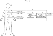
- FIG. 1 illustrates an example of a biological signal measuring apparatus.
- the biological signal measuring apparatus 10 includes interface A 111, interface Ad 112, interface B 113, interface Bd 114, a noise extracting unit 12, and a biological signal extracting unit 13.
- the biological signal measuring apparatus 10 illustrated in FIG. 1 is an example and may be modified in various ways based on the elements illustrated in FIG. 1 .
- the biological signal measuring apparatus 10 may include various numbers of interfaces.
- Interfaces A 111 and B 113 may detect a biological signal of an examinee 20 through electrical interfacing with the examinee 20 by touching the skin of the examinee 20.
- a biological signal of the examinee 20 may be measured based on the theory that there are different potentials between different parts of the skin of the examinee 20.
- a biological signal of the examinee 20 may be measured by a potential difference (i.e. voltage) between a pair of interfaces such as interfaces A 111 and B 113.
- a biological signal of the examinee 20 may be measured via a potential at one part of the skin of the examinee 20 or a combination of values may be detected via a plurality of interfaces at a plurality of parts of the skin of the examinee 20.
- the interfaces A 111 and B 113, and Ad 112 and Bd 114 are shown as being electrically connected to the noise extracting unit 12, it should also be appreciated that one or more of the interfaces 111 through 114 may wirelessly transmit the result of measuring the biological signal to the noise extracting unit 12.
- the interfaces 111 through 114 and the noise extracting unit 12 may include units performing the wireless communication.
- the interfaces 111 through 114 can be a separate device from the noise extracting unit 12.
- FIG. 2 illustrates an example of an equivalent circuit of the interfaces illustrated in FIG. 1 .
- the interfaces A 111 and B 113 denote elements that directly touch the skin of the examinee 20 to conduct electrical interfacing with the skin of the examinee 20 to measure a biological signal of the examinee 20.
- the interfaces A 111 and B 113 may be modeled as resistor-capacitor (RC) circuits as illustrated in FIG. 2 .
- interfaces A 111 and B 113 may be wet-type electrodes that are formed of a solid conductive material and coated with an electrolyte-containing gel.
- the electrodes may contact the skin of the examinee 20 via the gel.
- interfaces A 111 and B 113 may be dry-type electrodes that are formed of a solid conductive material and that directly touch the skin of the examinee 20.
- the skin of the examinee 20 is typically an excellent nonconductor that protects a living body from an external electrical impulse.
- the wet-type electrodes including solid type electrodes may be coated with a substance such as an electrolyte-containing gel including chlorine, a biological ion, and the like.
- an example of interfaces A 111 and B 113 being formed using a wet-type electrode is described with reference to the equivalent circuit of FIG. 2 .
- an interface may include a resistor Rg, a voltage source Ve, a capacitor Ce, and a resistor Re.
- the resistor Rg denotes resistance of an electrolyte of a wet-type electrode
- the voltage source Ve denotes a potential that is applied between two ends of the electrode
- the capacitor Ce denotes the capacitance in a charge double layer on a boundary surface between the electrode and the electrolyte
- the resistor Re denotes leakage resistance that occurs in the charge double layer.
- a charge double layer may be formed on the boundary surface between the electrode and the electrolyte, and motion of the electrode may vary charge distribution on the boundary surface between the electrode and the electrolyte.
- the variation of the motion of the electrode may vary a potential detected by the electrode.
- the interfaces A 111 and B 113 may move in different manners. Accordingly, potentials that are detected using the electrodes of the interfaces A 111 and B 113 may vary in different manners from each other, and this variation may create a fluctuation (i.e. noise) in a voltage between the interfaces A 111 and B 113.
- the noise generated by the fluctuation in the electrical characteristics of the interfaces A and B 111 and 113 is referred to as a motion artifact of a biological signal that is detected using the interfaces A 111 and B 113.
- a motion artifact may be generated for various factors other than as described above. As an example, if the skin of the examinee 20 is pulled, a motion artifact of 5-10 mV may be generated. This motion artifact may create noise in the biological signal detected from an examinee that is wearing the interfaces.
- a motion artifact signal as described above may be a low frequency signal of a frequency band that is similar to that of a biological signal that is detected by the interfaces A 111 and B 113. Accordingly, it may be difficult to remove the noise generated by the motion artifact using a general low pass or high pass filter.
- dummy interfaces Ad 112 and Bd 114 may be used to detect dummy signals that are different from a biological signal of the examinee 20 detected via the interfaces A 111 and B 113.
- the dummy interfaces Ad 112 and Bd 114 may detect dummy signals through interfacing with electrical characteristics different from those of the interfacing of the interfaces A 111 and B 113.
- a motion artifact signal of the biological signal may be traced using dummy signals that are detected by the dummy interfaces Ad 112 and Bd 114.
- the electrical characteristics of the interfaces Ad 112 and Bd 114 vary due to, for example, motion of the examinee 20
- variation aspects of dummy signals detected by the interfaces Ad 112 and Bd 114 may be similar to variation aspects of signals detected by the interfaces A 111 and B 113.
- the interface A 111 and the dummy interface Ad 112 may be disposed within a distance between each other so that an external noise fluctuation factor is almost simultaneously input to both the interface A 111 and the dummy interface Ad 112.
- the distance may be 0.5 mm, 0.75 mm, 1 mm, 1.5 mm, 2 mm, and the like. In other words, the distance may be in the range of 0.1mm ⁇ 10mm.
- the interface B 113 and the dummy interface Bd 114 may also be disposed within a distance so that an external noise fluctuation factor is almost simultaneously input to both the interface B 113 and the dummy interface Bd 114.
- the interface A 111 and the interface B 113 may be spaced apart by a distance for detecting a biological signal of the examinee 20.
- a fluctuation in the electrical characteristics of the interface A 111 due to an external factor such as motion of the examinee 20 may be similar to fluctuation in the electrical characteristics of the dummy interface Ad 112.
- a fluctuation of a voltage source of an equivalent circuit of the dummy interface Ad 112 may differ in scale from fluctuation of a voltage source of an equivalent circuit of the interface A 111 but may be proportional thereto.
- fluctuation of a voltage source of an equivalent circuit of the dummy interface Bd 114 may differ in scale from fluctuation of a voltage source of an equivalent circuit of the interface B 113 but may be proportional thereto.
- the noise extracting unit 12 may use the similarity between the fluctuation in the electrical characteristics of the interface A 111 and the fluctuation in the electrical characteristics of the dummy interface Ad 112, and the similarity between the fluctuation in the electrical characteristics of the interface B 113 and the fluctuation in the electrical characteristics of the dummy interface Bd 114, to extract a noise signal that is proportional to a motion artifact signal of a biological signal of the examinee 20 from among signals detected by the interfaces A 111 and B 113 and the dummy interfaces Ad 112 and Bd 114.
- the noise extracting unit 12 may use the similarity between the fluctuation in the voltage of the voltage source of the interface A 111 and the fluctuation in the voltage of the voltage source of the dummy interface Ad 112, and the similarity between the fluctuation in the voltage of the voltage source of the interface B 113 and the fluctuation in the voltage of the voltage source of the dummy interface Bd 114, to extract a noise signal that is proportional to a motion artifact signal of a biological signal of the examinee 20 from among signals detected by the interfaces A 111 and B 113 and the dummy interfaces Ad 112 and Bd 114.
- the signals detected via the interfaces A 111, B 113, Ad 112, and Bd114 may be small in size. Accordingly, the signals may be amplified for processing.
- the noise extracting unit 12 may include an amplifier for amplifying signals detected via the interfaces A 111, B 113, Ad 112, and Bd 114, an analog-to-digital (A/D) converter for converting the amplified, analog signals into digital signals, and a calculator for calculating the digital signals.
- A/D analog-to-digital
- the biological signal extracting unit 13 may detect an actual biological signal of the examinee 20 by removing a motion artifact signal from a biological signal that is detected by the interfaces A 111 and B 113 using a noise signal that is extracted by the noise extracting unit 12.
- the noise signal that is extracted by the noise extracting unit 12 may be proportional to the motion artifact signal, and thus the motion artifact signal of the biological signal may be removed using the noise signal extracted by the noise extracting unit 12.
- the biological signal extracting unit 13 may include an adaptive filter.
- the adaptive filter may be a digital filter that is capable of adjusting filter coefficients based on values that are fed back by the adaptive filter.
- the biological signal extracting unit 13 may adjust filter coefficients based on noise signals that are extracted by the noise extracting unit 12 and filter a biological signal corresponding to a waveform of a voltage between the interfaces A 111 and B 113 using the adjusted filter coefficients to remove a motion artifact signal from the biological signal.
- the noise extracting unit 12 and the biological signal extracting unit 13 may be an electronic circuit including the above electronic elements or other electronic elements. Electronic elements may not be classified by the noise extracting unit 12 and the biological signal extracting unit 13, because these mean functional blocks for classifying the above mentioned operations.
- the noise extracting unit 12 and the biological signal extracting unit 13 may be an electronic circuit, using an adaptive filter, removing a motion artifact signal from a biological signal that is detected by the interfaces A 111 and B 113, based on the signals detected via the interfaces A 111, B 113, Ad 112, and Bd114.
- the adaptive filter can perform operations detecting the motion artifact signal and the actual biological signal of the examinee 20.
- ECG electrocardiography
- the biological signal measuring apparatus 10 illustrated in FIG. 1 may be applied not only to ECG signals but also to other biological signals that may be electrically detected from the body of the examinee 20, such as brain wave signals, electromyogram signals, and the like.
- An ECG signal may be measured based on the characteristic that between the heart of the examinee 20 and different parts of the skin are different potential differences.
- an ECG signal may be detected by attaching a pair of electrodes to two parts of the skin of the examinee 20 and measuring a potential difference between the electrodes over a predetermined period of time.
- the measured potential difference between the two electrodes may be shown as a waveform signal that repeatedly rises and declines over time, and this ECG signal may be displayed and/or recorded as a waveform, for example, on a screen or a sheet of paper.
- a pair of electrodes that are attached to two parts of the skin of the examinee 20 is a unit for measuring one ECG signal and the electrodes may be referred to as leads.
- an ECG signal is measured using any of various numbers of leads, and the heart of the examinee 20 may be observed at different angles through the leads, respectively.
- ECG signals may be classified as a 3-lead, a 5-lead, a 12-lead, and the like, based on the number of leads.
- an ECG signal measuring apparatus described herein includes two leads, however, it should be appreciated that the biological signal measuring apparatus 10 may instead or also measure another number of leads, for example, a 3-lead, a 5-lead, or a 12-lead ECG signal.
- FIG. 3 illustrates an example of an ECG signal measuring apparatus.
- the ECG signal measuring apparatus is an example of the biological signal measuring apparatus 10 illustrated in FIG. 1 .
- descriptions already described with reference to the biological signal measuring apparatus 10 illustrated in FIG. 1 may be omitted here but also apply to the ECG signal measuring apparatus 30 illustrated in FIG. 3 .
- ECG signal measuring apparatus includes an electrode A 311 and an electrode B 313 that are formed by coating a flat substrate formed of silver (Ag) with silver chloride (AgCl) and are referred to as Ag/AgCl electrodes.
- dummy electrodes Ad 312 and Bd 314 are formed of a material that is different from that of the electrodes A 311 and B 313 so that the dummy electrodes Ad 312 and Bd 314 have electrical characteristics that are different from those of the electrodes A 311 and B 313.
- the dummy electrodes Ad 312 and Bd 314 may be formed of a flat substrate formed of gold (Au).
- a voltage between an output end p2 of the electrode A 311 and an output end q2 of the electrode B 313 may be calculated as shown in Equation 1 below.
- Vecg_p1 denotes a potential at an input end p1 of the electrode A 311
- Ve1 denotes a voltage between the input and output ends p1 and p2 of the electrode A 311.
- Vecg_q1 denotes a potential at an input end q1 of the electrode B 313
- Ve2 denotes a voltage between the input and output ends q1 and q2 of the electrode B 313.
- Vecg_p1 - Vecg_q1 denotes a pure ECG signal
- Vnoise denotes a motion artifact signal that is included in an ECG signal that is detected using the electrode A 311 and the electrode B 313.
- a voltage between the output end p2 of the electrode A 311 and an output end s2 of the dummy electrode Ad 312 may be calculated as shown in Equation 2.
- Vecg_s1 denotes a potential at an input end s1 of the dummy electrode Ad 312
- Ve1d denotes a voltage that is between the input and output ends s1 and s2 of the dummy electrode Ad 312.
- Vecg_p1 at the input end p1 of the electrode A 311 and Vecg_s1 at the input end s1 of the dummy electrode Ad 312 may be approximately the same.
- Vp2-s2 may be the same as Ve1 - Ve1d because Vecg_p1 - Vecg_s1 is considered to be equal to zero.
- a voltage that is between the output end q2 of the electrode B 313 and an output end t2 of the dummy electrode Bd 314 may be calculated as shown in Equation 3.
- Vecg_q1 denotes the potential at the input end q1 of the electrode B 313
- Ve2 denotes the voltage between the input and output ends q1 and q2 of the electrode B 313.
- Vecg_t1 denotes a potential at an input end t1 of the dummy electrode Bd 314
- Ve2d denotes a voltage that is between the input and output ends t1 and t2 of the dummy electrode Bd 314.
- Vecg_q1 at the input end q1 of the electrode B 313 and Vecg_t1 at the input end t1 of the dummy electrode Bd 314 may be approximately the same.
- Vq2-t2 may be the same as Ve2 - Ve2d because Vecg_q1-Vecg_t1 is considered to be equal to zero.
- V(p2-s2)-(q2-t2) is a value obtained by subtracting Vq2-t2 of Equation 3 from Vp2-s2 of Equation 2 and may be calculated as shown in Equation 4.
- a is a proportional constant. Because the electrode A 311 and the dummy electrode Ad 312 are placed near to each other, a fluctuation of a voltage source of an equivalent circuit of the dummy electrode Ad 312 may be approximately the same as that of a voltage source of an equivalent circuit of the electrode A 311. Accordingly, Ve1 d may be equal to b * Ve1.
- a fluctuation of a voltage source of an equivalent circuit of the dummy electrode Bd 314 may be approximately the same as that of a voltage source of an equivalent circuit of the electrode B 313. Accordingly, Ve2d may be equal to b * Ve2.
- b represents a proportional constant
- a 1 - b. Referring to Equation 4 below, (V(p2-s2)-(q2-t2)) is proportional to Vnoise included in a detected biological signal.
- the noise extracting unit 32 may extract a signal that is proportional to a motion artifact signal that is included in an ECG signal detected by the electrode A 311 and the electrode B 313. For example, the noise extracting unit 32 may measure a voltage Vp2-s2 between the output end p2 of the electrode A 311 and the output end s2 of the dummy electrode Ad 312 and may measure a voltage (Vq2-t2) between the output end q2 of the electrode B 313 and the output end t2 of the dummy electrode Bd 314, and calculate the difference between the measured voltages.
- the electrode A 311 and the dummy electrode Ad 312 may be relatively small in size.
- one electrode and one dummy electrode are divided into a plurality of unit electrodes and a plurality of unit dummy electrodes, respectively. Also described are various examples in which the unit dummy electrodes are alternately arranged between the unit electrodes, such that the electrode A 311 and the dummy electrode Ad 312 are placed near to each other and such that a sufficient amount of current may be measured to accurately measure a biological signal of the examinee 20.
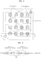
- FIG. 4 illustrates an example of a latticed electrode substrate of the ECG signal measuring apparatus illustrated in FIG. 3 .
- FIG. 4 illustrates an arrangement of the electrode A 311 and the dummy electrode Ad 312 of the ECG signal measuring apparatus 30 that are illustrated in FIG. 3 .
- a plurality of unit electrodes corresponding to the electrode A 311 are arranged in a lattice structure on a substrate that may be formed of an insulation material, and a plurality of unit dummy electrodes corresponding to the dummy electrode Ad 312 are arranged between the unit electrodes in a lattice structure.
- the unit electrodes arranged in a lattice structure are connected to a node p2 that corresponds to an output end of the electrode A 311. Accordingly, current detected through the unit electrodes is collected by the node p2.
- the unit dummy electrodes arranged in a lattice structure are connected to a node s2 that corresponds to an output end of the dummy electrode Ad 312. Accordingly, current detected through the unit dummy electrodes is collected by the node s2.
- the electrode A 311 and the dummy electrode Ad 312 may be placed near to each other, and a sufficient amount of current for accurately measuring a biological signal of the examinee 20 may be detected.
- FIG. 5 illustrates an example of a cross-sectional view of the latticed electrode substrate of the ECG signal measuring apparatus 30 illustrated in FIG. 4 .
- the electrode substrate of FIG. 4 is cut along a line AA'.
- conductive portions denoted by solid oblique lines correspond to a conductor portion of the unit electrodes that are connected to the node p2
- conductive portions denoted by dotted oblique lines correspond to a conductor portion of the unit dummy electrodes that are connected to the node s2.
- An electrolyte-containing gel may be adhered to surfaces of each of the unit electrodes and the unit dummy electrodes.
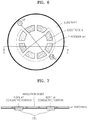
- FIG. 6 illustrates an example of a circular electrode substrate of the ECG signal measuring apparatus 30 illustrated in FIG. 3 .
- FIG. 6 shows an arrangement of the electrode A 311 and the dummy electrode Ad 312 that is another example of that shown in FIG. 3 .
- a plurality of unit electrodes corresponding to the electrode A 311 are arranged in a circular structure on a substrate that may be formed of an insulation material, and a plurality of unit dummy electrodes corresponding to the dummy electrode Ad 312 are arranged between the unit electrodes in a circular structure.
- the unit electrodes arranged in a circular structure are connected to the node p2 that corresponds to an output end of the electrode A 311. Accordingly, current detected through the unit electrodes may be collected by the node p2.
- the unit dummy electrodes arranged in a circular structure are connected to the node s2 that corresponds to an output end of the dummy electrode Ad 312.
- the electrode A 311 and the dummy electrode Ad 312 may be placed near to each other, and a sufficient amount of current for accurately measuring a biological signal of the examinee 20 may be detected.
- FIG. 7 illustrates an example of a cross-sectional view of the circular electrode substrate of the ECG signal measuring apparatus illustrated in FIG. 6 .
- the electrode substrate of FIG. 6 is cut along a line AA'.
- conductive portions denoted by solid oblique lines correspond to conductor portions of the unit electrodes that are connected to the node p2
- conductive portions denoted by dotted oblique lines correspond to conductor portions of the unit dummy electrodes that are connected to the node s2.
- An electrolyte-containing gel may be adhered to the surfaces of each of the unit electrodes and the unit dummy electrodes.
- an insulation sheet may be formed on the substrate on which the unit electrodes and the unit dummy electrodes are arranged. In this example, the use of the insulation sheet may block an external current from being supplied to the electrodes, and a more accurate measurement of a biological signal of the examinee 20 may be obtained.
- FIG. 8 illustrates another example of an ECG signal measuring apparatus.
- the ECG signal measuring apparatus 80 illustrated in FIG. 8 is another example of the biological signal measuring apparatus 10 that is illustrated in FIG. 1 .
- descriptions already described with reference to the biological signal measuring apparatus 10 illustrated in FIG. 1 may be omitted here but also apply to the ECG signal measuring apparatus 80 illustrated in FIG. 8 .
- an electrode A 811 and a dummy electrode Ad 812 are formed of the same material, for example, Ag/AgCl.
- An electrode B 813 and a dummy electrode Bd 814 are also formed of the same material.
- insulation layers may be formed in the dummy electrodes Ad 812 and Bd 814, at portions that touch the skin of the examinee 20 so as to block current that flows from the skin of the examinee 20 to the dummy electrodes Ad 812 and Bd 814.
- input ends of the dummy electrodes Ad 812 and Bd 814 touching the skin of the examinee 20 may be coated with an insulation material such as rubber.
- an insulation material such as rubber.
- external bias voltage sources are connected to the input ends of the dummy electrode 812 to apply predetermined voltages to the dummy electrodes Ad 812 and Bd 814.
- a voltage between an output end p2 of electrode A 811 and an output end q2 of the electrode B 813 may be calculated as shown in Equation 5 below.
- Vecg_p1 denotes a potential at an input end p1 of the electrode A 811
- Ve1 denotes a voltage between the input and output ends p1 and p2 of the electrode A 811.
- Vecg_q1 denotes a potential at an input end q1 of the electrode B 813
- Ve2 denotes a voltage between the input and output ends q1 and q2 of the electrode B 813.
- Vecg_p1-Vecg_q1 is a pure ECG signal
- Vnoise denotes a motion artifact signal that is included in a ECG signal that is detected by the electrode A 811 and the electrode B 813.
- a voltage between an output end s2 of the dummy electrode Ad 812 corresponding to electrode A 811 and an output end t2 of the dummy electrode Bd 814 corresponding to electrode B 813 may be calculated as shown in Equation 6 below.
- Vbias1 denotes a potential at an input end s1 of the dummy electrode Ad 812
- Ve1d denotes a voltage between the input and output ends s1 and s2 of the dummy electrode Ad 812.
- Vbias2 denotes a potential at an input end t1 of the dummy electrode Bd 814
- Ve2d denotes a voltage between the input and output ends t1 and t2 of the dummy electrode Bd 814.
- Vbias1 and Vbias2 correspond to a potential of an external bias voltage source.
- the potentials of the external bias voltage sources respectively connected to the dummy electrodes Ad and Bd 812 and 814 may be adjusted as desired.
- Vs2-t2 is proportional to Vnoise that corresponds to a motion artifact signal that is included in an ECG signal detected using the electrode A 811 and the electrode B 813.
- the noise extracting unit 12 measures a voltage between the output end s2 of the dummy electrode Ad 812 and the output end t2 of the dummy electrode Bd 814, thereby extracting a signal proportional to Vnoise.
- Vbias1 and Vbias2 are approximately the same.
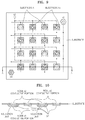
- FIG. 9 illustrates an example of a latticed electrode substrate of the ECG signal measuring apparatus 80 illustrated in FIG. 8 .
- FIG. 9 illustrates an example of the electrode A 811 and the dummy electrode Ad 812 of the ECG signal measuring apparatus 80 illustrated in FIG. 8 .
- the latticed electrode substrate of the ECG signal measuring apparatus 80 has the same structure as the latticed electrode substrate illustrated in FIG. 4 except that the insulation layers are formed in the dummy electrodes Ad 812 and Bd 814.
- node s1 for supplying power of a predetermined voltage to the unit dummy electrodes is included in addition to the nodes p2 and s2 illustrated in FIG. 4 .
- FIG. 10 illustrates an example of a cross-sectional view of the latticed electrode substrate of the ECG signal measuring apparatus illustrated in FIG. 9 .
- the electrode substrate of FIG. 9 is cut along a line AA'.
- conductive portions denoted by solid oblique lines correspond to conductor portions of the unit electrodes that are connected to the node p2
- conductive portions denoted by dotted oblique lines correspond to conductor portions of the unit dummy electrodes that are connected to the node s2.
- an electrolyte-containing gel is adhered to the surfaces of each of the unit electrodes and the unit dummy electrodes.
- the unit dummy electrodes include an insulation unit.
- FIG. 11 illustrates an example of a circular electrode substrate of the ECG signal measuring apparatus 80 illustrated in FIG. 8 .
- FIG. 11 illustrates another example of the electrode A 811 and the dummy electrode Ad 812 illustrated in FIG. 8 .
- the circular electrode substrate of FIG. 11 has the same structure as the circular electrode substrate illustrated in FIG. 6 except that the insulation layers are formed in the dummy electrodes Ad 812 and Bd 814.
- node s1 for supplying power of a predetermined voltage to the unit dummy electrodes is included in addition to the nodes p2 and s2 illustrated in FIG. 6 .
- FIG. 12 illustrates an example of a cross-sectional view of the circular electrode substrate of the ECG signal measuring apparatus illustrated in FIG. 11 .
- the electrode substrate of FIG. 11 is cut along a line AA'.
- conductive portions denoted by solid oblique lines correspond to conductor portions of the unit electrodes that are connected to the node p2
- conductive portions denoted by dotted oblique lines corresponds to a conductor portion of the unit dummy electrodes that are connected to the node s2.
- an electrolyte-containing gel is adhered to the surfaces of each of the unit electrodes and the unit dummy electrodes.
- an insulation sheet may be formed on the substrate on which the unit electrodes and the unit dummy electrodes are arranged.
- the unit dummy electrodes include an insulation unit.
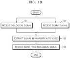
- FIG. 13 illustrates an example of a method for measuring a biological signal.
- the method illustrated in FIG. 13 includes operations that are time-sequentially processed in the biological signal measuring apparatus 10 illustrated in FIG. 1 . Accordingly, descriptions already described with reference to the biological signal measuring apparatus 10 illustrated in FIG. 1 may be omitted here but also apply to the method illustrated in FIG. 13 .
- the noise extracting unit 12 receives a biological signal of the examinee 20 that is detected via the interfaces A 111 and B 113 that are touching the skin of the examinee 20.
- the noise extracting unit 12 receives dummy signals detected via the dummy interfaces Ad 112 and Bd 114 which have electrical characteristics that are different from those of the interfaces A 111 and B 113.
- the noise extracting unit 12 extracts a signal that is proportional to noise due to fluctuations in the electrical characteristics of the biological signal of the examinee 20 received in 131 and the dummy signals received in operation 132.
- the biological signal extracting unit 13 uses the signal extracted in 133 to remove noise generated due to the fluctuations in the electrical characteristics of the interfaces A 111 and B 113, from the biological signal detected in 131, thereby more accurately detecting a biological signal of the examinee 20.
- the biological signal of the examinee 20 may be more accurately measured.
- the ECG signal of the examinee 20 may be more accurately measured.
- the noise extracting unit 12 and the biological signal extracting unit 13 illustrated in FIG. 1 may include an amplifier, an A/D converter, a calculator, a digital filter, and the like, and an operation sequence thereof, that is, the method of measuring a biological signal according to the embodiment of FIG. 13 may be written as computer programs and be implemented in general-use digital computers that execute the computer programs using a computer readable recording medium.
- the present disclosure also pertains to a computer readable storage medium comprising program instructions to cause a processor to execute a method of measuring a biological signal, the method including receiving a biological signal of an examinee from at least one interface that touches skin of the examinee, receiving a dummy signal that is different from the biological signal, from at least one dummy interface that has electrical characteristics that are different from those of the at least one interface, and removing noise generated by a fluctuation in the electrical characteristics of the at least one interface from the biological signal using the biological signal and the dummy signal.
- the present disclosure also pertains to an interface device for detecting a biological signal of an examinee and a signal for removing noise of the biological signal, the interface including at least one interface for detecting a biological signal of the examinee through electrical interfacing with skin of the examinee, and at least one dummy interface for detecting a dummy signal that is different from the biological signal, through the at least one dummy interface that has electrical characteristics that are different from those of the at least one interface.
- the present disclosure also pertains to a device for use in detecting a biological signal, the device including a first electrode having a first electrical characteristic, a second electrode spaced apart from the first electrode by a first distance and having a second electrical characteristic different from the first electrical characteristic, a third electrode having a third electrical characteristic and spaced apart from the first electrode by a second distance that is greater than the first distance, and a fourth electrode having a fourth electrical characteristic different form the third electrical characteristic and spaced apart from the third electrode by a third distance that is less than the second distance.
- the first distance and the third distance may be substantially equal.
- the first electrical characteristic and the third electrical characteristic may be substantially the same.
- the second electrical characteristic and the fourth electrical characteristic may be substantially the same.
- the first electrode may include a first metal and the second electrode may includes a second metal that is different from the first metal.
- the first electrode further may include a coating on the first metal.
- the first metal may be silver (Ag) and the coating may be silver chloride (AgCl).
- the second metal may be gold (Au).
- the first and second electrodes may include a metal.
- the second electrode further may include an insulation material.
- the first and second electrodes may include a coating on the metal.
- the metal is silver (Ag) and the coating may be silver chloride (AgCl).
- the insulation material may be rubber.
- the first, second, third, and fourth electrodes may form a unit and the device may include two or more of the units.
- the first, second, third, and fourth electrodes may be arranged in a straight pattern.
- the first, second, third, and fourth electrodes may be arranged in a curved pattern.
- the curved pattern may be a circular pattern.
- the present disclosure also pertains to a biological signal measuring apparatus including at least one interface for detecting a biological signal of an examinee through electrical interfacing with a skin of the examinee, at least one dummy interface for detecting a dummy signal that is different from the biological signal, through the at least one dummy interface that has electrical characteristics that are different from those of the at least one interface, and a electronic circuit for removing a noise generated due to a fluctuation in the electrical characteristics of the at least one interface from the detected biological signal, based on the biological signal and the dummy signal.
- the processes, functions, methods, and/or software described herein may be recorded, stored, or fixed in one or more computer-readable storage media that includes program instructions to be implemented by a computer to cause a processor to execute or perform the program instructions.
- the media may also include, alone or in combination with the program instructions, data files, data structures, and the like.
- the media and program instructions may be those specially designed and constructed, or they may be of the kind well-known and available to those having skill in the computer software arts.
- Examples of computer-readable storage media include magnetic media, such as hard disks, floppy disks, and magnetic tape; optical media such as CD ROM disks and DVDs; magneto-optical media, such as optical disks; and hardware devices that are specially configured to store and perform program instructions, such as read-only memory (ROM), random access memory
- RAM random access memory
- program instructions include machine code, such as produced by a compiler, and files containing higher level code that may be executed by the computer using an interpreter.
- the described hardware devices may be configured to act as one or more software modules that are recorded, stored, or fixed in one or more computer-readable storage media, in order to perform the operations and methods described above, or vice versa.
- a computer-readable storage medium may be distributed among computer systems connected through a network and computer-readable codes or program instructions may be stored and executed in a decentralized manner.
Landscapes
- Health & Medical Sciences (AREA)
- Life Sciences & Earth Sciences (AREA)
- Engineering & Computer Science (AREA)
- General Health & Medical Sciences (AREA)
- Public Health (AREA)
- Veterinary Medicine (AREA)
- Animal Behavior & Ethology (AREA)
- Surgery (AREA)
- Physics & Mathematics (AREA)
- Molecular Biology (AREA)
- Biophysics (AREA)
- Pathology (AREA)
- Biomedical Technology (AREA)
- Heart & Thoracic Surgery (AREA)
- Medical Informatics (AREA)
- Signal Processing (AREA)
- Psychiatry (AREA)
- Physiology (AREA)
- Artificial Intelligence (AREA)
- Computer Vision & Pattern Recognition (AREA)
- Cardiology (AREA)
- Power Engineering (AREA)
- Measurement And Recording Of Electrical Phenomena And Electrical Characteristics Of The Living Body (AREA)
- Measuring And Recording Apparatus For Diagnosis (AREA)
Description
- The invention relates to a biological signal measuring apparatus according to the preamble of
claim 1 and to a method using such a measuring apparatus, for accurately measuring a biological signal by removing noise from the biological signal. -
US 5,704,365 discloses a method of reducing noise in a signal that represents a physiologic process includes obtaining multiple input signals, measuring a relationship between noise content of the input signals, and combining the input signals in consideration of the measured relationship to produce an output signal having low noise content. The multiple input signals may include, for example, two or more primary physiologic input signals or one or more primary physiologic input signals and two or more secondary input signals that represent noise. -
WO2010/023615 discloses a system and a method in which an electrophysiological signal is sensed capacitively with at least two closely spaced electrodes such that the electrodes experience strongly correlated skin-electrode distance variations. To be able to derive a motion artifact signal, the capacitive coupling between the electrodes and skin is made intentionally different. With a signal processing means the motion artifact signal can be removed from the measured signal to leave only the desired electrophysiological signal. -
US 2001/0051821 discloses a medical electrode system with electrodes capable of delivering synchronized cardioversion energy pulses as well as defibrillation energy pulses to a patient. At least one electrode in an electrode set has a substrate with an adhesive surface, and conductors in communication with the substrate. -
US 6,073,039 discloses an electrode assembly for monitoring bioelectric signals includes a first electrode member and a second electrode member disposed around the first electrode member. When the electrode assembly is placed on a body of a person, a bioelectric signal is monitored by measuring the electrical potential between the first and second electrode members with the measurement device. The first and second electrode members may be single electrodes or two or more electrodes connected by conductors. - To examine a patient's health, various medical equipment has been used and more are currently being developed. Various medical equipment may be used to measure electrical biological signals of a patient such as electrocardiography signals, brain wave signals, electromyogram signals, and the like. Recently, equipment for measuring biological signals have gained more attention as they provide convenience for patients and examination results quickly.
- However, various factors may create noise that affects the measurement of the biological signals. The noise may disrupt the biological signal and prevent an accurate reading from being detected.
- The biological signal measuring apparatus is distinguished by the features of the characterizing portion of
claim 1. - The noise signal may be generated by a fluctuation in electrical characteristics of an interface that measures the biological signal and an interface that measures the dummy signal.
- The biological signal may be measured with a first interface and the dummy signal may be measured with a second interface, and the first interface and the second interface may have different electrical characteristics.
- The first interface and the second interface may be within a predetermined distance from each other on an examinee's body.
- The different electrical characteristics may be generated because the first interface comprises a first material and the second interface comprises a second material that is different from the first material.
- The first material may comprise a silver substrate that is coated with silver chloride and the second material may comprise gold.
- The first interface and the second interface may be formed of the same material and the different electrical characteristics may be generated because the second interface includes an insulation layer between the interface and the skin of an examinee's body.
- The at least one interface and the at least one dummy interface may be placed within a predetermined distance from each other.
- The noise extracting unit may extract the signal that is proportional to the noise using a similarity between fluctuations in the electrical characteristics of the at least one interface and the at least one dummy interface, which is due to the at least one interface and the at least one dummy interface being placed near to each other.
- An electrode of the at least one dummy interface may be formed of a material that is different from that of an electrode of the at least one interface so that the at least one dummy interface has electrical characteristics that are different from those of the at least one interface.
- The at least one interface may comprise a first electrode and a second electrode, the at least one dummy interface comprises a first dummy electrode and a second dummy electrode, and the noise extracting unit extracts the signal that is proportional to the noise by measuring a voltage between the first electrode and the first dummy electrode, measuring a voltage between the second electrode and the second dummy electrode, and calculating a difference in the measured voltages.
- The at least one dummy interface may have electrical characteristics that are different from those of the at least one interface because the at least one dummy interface may have formed therein an insulation layer that is located at a portion of the at least one dummy interface that touches the skin of the examinee to reduce current from flowing from the skin of the examinee to the at least one dummy interface.
- The at least one interface may comprise a first electrode and a second electrode, the at least one dummy interface may comprise a first dummy electrode and a second dummy electrode, the noise extracting unit may extract the signal that is proportional to the noise by measuring a voltage between the first dummy electrode and the second dummy electrode, and potentials of voltage sources of the first dummy electrode and the second dummy electrode may be approximately the same.
- The biological signal may be an electrocardiography signal of the examinee, and the noise may be a motion artifact that is generated by fluctuation in the electrical characteristics of the at least one interface due to an external factor caused by motion of the examinee.
- In another aspect, there is provided a method of measuring a biological signal, according to claim 5.The at least one interface and the at least one dummy interface may be placed within a predetermined distance from each other.
- The removing of noise may comprise extracting a signal that is proportional to the noise generated by the fluctuation in the electrical characteristics of the at least one interface from the biological signal and the dummy signal, and removing the noise from the detected biological signal using the extracted signal.
- In the extracting of the signal that is proportional to the noise, the signal that is proportional to the noise may be extracted using a similarity between fluctuations of the electrical characteristics of the at least one interface and the at least one dummy interface, which is due to the at least one interface and the at least one dummy interface being placed near to each other.
- The biological signal may be an electrocardiography signal of the examinee, and the noise may be a motion artifact that is generated by a fluctuation in the electrical characteristics of the interface due to external factor caused by motion of the examinee.
- In another aspect, there is provided a computer readable storage medium comprising program instructions to cause a processor to execute a method of measuring a biological signal, the method including receiving a biological signal of an examinee from at least one interface that touches skin of the examinee, receiving a dummy signal that is different from the biological signal, from at least one dummy interface that has electrical characteristics that are different from those of the at least one interface, and removing noise generated by a fluctuation in the electrical characteristics of the at least one interface from the biological signal using the biological signal and the dummy signal.
- Other features and aspects may be apparent from the following detailed description, the drawings, and the claims.
-
FIG. 1 is a diagram illustrating an example of a biological signal measuring apparatus. -
FIG. 2 is a diagram illustrating an example of an equivalent circuit of the interfaces illustrated inFIG. 1 . -
FIG. 3 is a diagram illustrating an example of an electrocardiography signal measuring apparatus. -
FIG. 4 is a diagram illustrating an example of a latticed electrode substrate of the electrocardiography signal measuring apparatus illustrated inFIG. 3 . -
FIG. 5 is a diagram illustrating an example of a cross-sectional view of the latticed electrode substrate of the electrocardiography signal measuring apparatus illustrated inFIG. 4 . -
FIG. 6 is a diagram illustrating an example of a circular electrode substrate of the electrocardiography signal measuring apparatus illustrated inFIG. 3 . -
FIG. 7 is a diagram illustrating an example of a cross-sectional view of the circular electrode substrate of the electrocardiography signal measuring apparatus illustrated inFIG. 6 . -
FIG. 8 is diagram illustrating another example of an electrocardiography signal measuring apparatus. -
FIG. 9 is a diagram illustrating an example of a latticed electrode substrate of the electrocardiography signal measuring apparatus illustrated inFIG. 8 . -
FIG. 10 is a diagram illustrating an example of cross-sectional view of the latticed electrode substrate of the electrocardiography signal measuring apparatus illustrated inFIG. 9 . -
FIG. 11 is a diagram illustrating an example of a circular electrode substrate of the electrocardiography signal measuring apparatus illustrated inFIG. 8 . -
FIG. 12 is a diagram illustrating an example of a cross-sectional view of the circular electrode substrate of the electrocardiography signal measuring apparatus illustrated inFIG. 11 . -
FIG. 13 is a flowchart illustrating an example of a method for measuring a biological signal. - The following detailed description is provided to assist the reader in gaining a comprehensive understanding of the methods, apparatuses, and/or systems described herein. Accordingly, various changes, modifications, and equivalents of the methods, apparatuses, and/or systems described herein will be suggested to those of ordinary skill in the art. Also, descriptions of well-known functions and constructions may be omitted for increased clarity and conciseness.
- In various examples, to help an examiner in recognizing a biological signal of an examinee, a display or a sheet of paper may be added in addition to the configurations for measuring a biological signal of an examinee.
-
FIG. 1 illustrates an example of a biological signal measuring apparatus. - Referring to
FIG. 1 , the biologicalsignal measuring apparatus 10 includesinterface A 111, interface Ad 112,interface B 113,interface Bd 114, anoise extracting unit 12, and a biologicalsignal extracting unit 13. The biologicalsignal measuring apparatus 10 illustrated inFIG. 1 is an example and may be modified in various ways based on the elements illustrated inFIG. 1 . For example, while four interfaces A, Ad, B, andBd 111 through 114 are illustrated inFIG. 1 , the biologicalsignal measuring apparatus 10 may include various numbers of interfaces. -
Interfaces A 111 andB 113 may detect a biological signal of anexaminee 20 through electrical interfacing with theexaminee 20 by touching the skin of theexaminee 20. As an example, a biological signal of theexaminee 20 may be measured based on the theory that there are different potentials between different parts of the skin of theexaminee 20. For example, a biological signal of theexaminee 20 may be measured by a potential difference (i.e. voltage) between a pair of interfaces such asinterfaces A 111 andB 113. It should also be understood that a biological signal of theexaminee 20 may be measured via a potential at one part of the skin of theexaminee 20 or a combination of values may be detected via a plurality of interfaces at a plurality of parts of the skin of theexaminee 20. - While the
interfaces A 111 andB 113, and Ad 112 andBd 114 are shown as being electrically connected to thenoise extracting unit 12, it should also be appreciated that one or more of theinterfaces 111 through 114 may wirelessly transmit the result of measuring the biological signal to thenoise extracting unit 12. For wireless communication between theinterfaces 111 through 114 and thenoise extracting unit 12, theinterfaces 111 through 114 and thenoise extracting unit 12 may include units performing the wireless communication. In this case, theinterfaces 111 through 114 can be a separate device from thenoise extracting unit 12. -
FIG. 2 illustrates an example of an equivalent circuit of the interfaces illustrated inFIG. 1 . - Referring to
FIGS. 1-2 , the interfaces A 111 andB 113 denote elements that directly touch the skin of theexaminee 20 to conduct electrical interfacing with the skin of theexaminee 20 to measure a biological signal of theexaminee 20. The interfaces A 111 andB 113 may be modeled as resistor-capacitor (RC) circuits as illustrated inFIG. 2 . - For example, interfaces A 111 and
B 113 may be wet-type electrodes that are formed of a solid conductive material and coated with an electrolyte-containing gel. In this example, the electrodes may contact the skin of theexaminee 20 via the gel. As another example, interfaces A 111 andB 113 may be dry-type electrodes that are formed of a solid conductive material and that directly touch the skin of theexaminee 20. The skin of theexaminee 20 is typically an excellent nonconductor that protects a living body from an external electrical impulse. To mitigate resistance of the skin of theexaminee 20, the wet-type electrodes including solid type electrodes may be coated with a substance such as an electrolyte-containing gel including chlorine, a biological ion, and the like. Hereinafter, an example of interfaces A 111 andB 113 being formed using a wet-type electrode is described with reference to the equivalent circuit ofFIG. 2 . - Referring to
FIG. 2 , an interface may include a resistor Rg, a voltage source Ve, a capacitor Ce, and a resistor Re. The resistor Rg denotes resistance of an electrolyte of a wet-type electrode, the voltage source Ve denotes a potential that is applied between two ends of the electrode, the capacitor Ce denotes the capacitance in a charge double layer on a boundary surface between the electrode and the electrolyte, and the resistor Re denotes leakage resistance that occurs in the charge double layer. - In various aspects, a charge double layer may be formed on the boundary surface between the electrode and the electrolyte, and motion of the electrode may vary charge distribution on the boundary surface between the electrode and the electrolyte. The variation of the motion of the electrode may vary a potential detected by the electrode. The interfaces A 111 and
B 113 may move in different manners. Accordingly, potentials that are detected using the electrodes of the interfaces A 111 andB 113 may vary in different manners from each other, and this variation may create a fluctuation (i.e. noise) in a voltage between the interfaces A 111 andB 113. The noise generated by the fluctuation in the electrical characteristics of the interfaces A andB B 113. A motion artifact may be generated for various factors other than as described above. As an example, if the skin of theexaminee 20 is pulled, a motion artifact of 5-10 mV may be generated. This motion artifact may create noise in the biological signal detected from an examinee that is wearing the interfaces. - A motion artifact signal as described above may be a low frequency signal of a frequency band that is similar to that of a biological signal that is detected by the interfaces A 111 and
B 113. Accordingly, it may be difficult to remove the noise generated by the motion artifact using a general low pass or high pass filter. As illustrated inFIG. 1 , to remove a motion artifact that may be generated as described above,dummy interfaces Ad 112 andBd 114 may be used to detect dummy signals that are different from a biological signal of theexaminee 20 detected via the interfaces A 111 andB 113. The dummy interfacesAd 112 andBd 114 may detect dummy signals through interfacing with electrical characteristics different from those of the interfacing of the interfaces A 111 andB 113. - To remove a motion artifact of a biological signal of the
examinee 20, a motion artifact signal of the biological signal may be traced using dummy signals that are detected by the dummy interfacesAd 112 andBd 114. In this example, if the electrical characteristics of theinterfaces Ad 112 andBd 114 vary due to, for example, motion of theexaminee 20, variation aspects of dummy signals detected by theinterfaces Ad 112 andBd 114 may be similar to variation aspects of signals detected by the interfaces A 111 andB 113. For example, theinterface A 111 and thedummy interface Ad 112 may be disposed within a distance between each other so that an external noise fluctuation factor is almost simultaneously input to both theinterface A 111 and thedummy interface Ad 112. As an example, the distance may be 0.5 mm, 0.75 mm, 1 mm, 1.5 mm, 2 mm, and the like. In other words, the distance may be in the range of 0.1mm∼10mm. Theinterface B 113 and thedummy interface Bd 114 may also be disposed within a distance so that an external noise fluctuation factor is almost simultaneously input to both theinterface B 113 and thedummy interface Bd 114. In contrast, theinterface A 111 and theinterface B 113 may be spaced apart by a distance for detecting a biological signal of theexaminee 20. - For example, if the
interface A 111 and thedummy interface Ad 112 are attached to the skin of theexaminee 20 while near to each other, motions of the electrodes of theinterface A 111 and thedummy interface Ad 112 may be approximately the same. As a result, a fluctuation in the electrical characteristics of theinterface A 111 due to an external factor such as motion of theexaminee 20 may be similar to fluctuation in the electrical characteristics of thedummy interface Ad 112. In this example, a fluctuation of a voltage source of an equivalent circuit of thedummy interface Ad 112 may differ in scale from fluctuation of a voltage source of an equivalent circuit of theinterface A 111 but may be proportional thereto. Likewise, fluctuation of a voltage source of an equivalent circuit of thedummy interface Bd 114 may differ in scale from fluctuation of a voltage source of an equivalent circuit of theinterface B 113 but may be proportional thereto. The nearer an interface and a dummy interface thereof are to each other, the greater the above-described proportional effect. - The
noise extracting unit 12 may use the similarity between the fluctuation in the electrical characteristics of theinterface A 111 and the fluctuation in the electrical characteristics of thedummy interface Ad 112, and the similarity between the fluctuation in the electrical characteristics of theinterface B 113 and the fluctuation in the electrical characteristics of thedummy interface Bd 114, to extract a noise signal that is proportional to a motion artifact signal of a biological signal of the examinee 20 from among signals detected by the interfaces A 111 andB 113 and the dummy interfacesAd 112 andBd 114. - For example, the
noise extracting unit 12 may use the similarity between the fluctuation in the voltage of the voltage source of theinterface A 111 and the fluctuation in the voltage of the voltage source of thedummy interface Ad 112, and the similarity between the fluctuation in the voltage of the voltage source of theinterface B 113 and the fluctuation in the voltage of the voltage source of thedummy interface Bd 114, to extract a noise signal that is proportional to a motion artifact signal of a biological signal of the examinee 20 from among signals detected by the interfaces A 111 andB 113 and the dummy interfacesAd 112 andBd 114. - The signals detected via the interfaces A 111,
B 113,Ad 112, and Bd114 may be small in size. Accordingly, the signals may be amplified for processing. For example, thenoise extracting unit 12 may include an amplifier for amplifying signals detected via the interfaces A 111,B 113,Ad 112, andBd 114, an analog-to-digital (A/D) converter for converting the amplified, analog signals into digital signals, and a calculator for calculating the digital signals. - The biological
signal extracting unit 13 may detect an actual biological signal of theexaminee 20 by removing a motion artifact signal from a biological signal that is detected by the interfaces A 111 andB 113 using a noise signal that is extracted by thenoise extracting unit 12. For example, the noise signal that is extracted by thenoise extracting unit 12 may be proportional to the motion artifact signal, and thus the motion artifact signal of the biological signal may be removed using the noise signal extracted by thenoise extracting unit 12. The biologicalsignal extracting unit 13 may include an adaptive filter. The adaptive filter may be a digital filter that is capable of adjusting filter coefficients based on values that are fed back by the adaptive filter. For example, the biologicalsignal extracting unit 13 may adjust filter coefficients based on noise signals that are extracted by thenoise extracting unit 12 and filter a biological signal corresponding to a waveform of a voltage between the interfaces A 111 andB 113 using the adjusted filter coefficients to remove a motion artifact signal from the biological signal. - The
noise extracting unit 12 and the biologicalsignal extracting unit 13 may be an electronic circuit including the above electronic elements or other electronic elements. Electronic elements may not be classified by thenoise extracting unit 12 and the biologicalsignal extracting unit 13, because these mean functional blocks for classifying the above mentioned operations. For example, thenoise extracting unit 12 and the biologicalsignal extracting unit 13 may be an electronic circuit, using an adaptive filter, removing a motion artifact signal from a biological signal that is detected by the interfaces A 111 andB 113, based on the signals detected via the interfaces A 111,B 113,Ad 112, and Bd114. In this example, the adaptive filter can perform operations detecting the motion artifact signal and the actual biological signal of theexaminee 20. - An example of a biological signal that may be measured using a waveform of a voltage detected between the two interfaces A 111 and
B 113 is an electrocardiography (ECG) signal. For example, as the heart of theexaminee 20 repeatedly beats, a potential difference between different parts of the skin of theexaminee 20 may change. A graph illustrating the electrical activity of the heart as described above is referred to as an ECG signal. As another example, the biologicalsignal measuring apparatus 10 illustrated inFIG. 1 may be applied not only to ECG signals but also to other biological signals that may be electrically detected from the body of theexaminee 20, such as brain wave signals, electromyogram signals, and the like. - An ECG signal may be measured based on the characteristic that between the heart of the
examinee 20 and different parts of the skin are different potential differences. Generally, an ECG signal may be detected by attaching a pair of electrodes to two parts of the skin of theexaminee 20 and measuring a potential difference between the electrodes over a predetermined period of time. The measured potential difference between the two electrodes may be shown as a waveform signal that repeatedly rises and declines over time, and this ECG signal may be displayed and/or recorded as a waveform, for example, on a screen or a sheet of paper. - A pair of electrodes that are attached to two parts of the skin of the
examinee 20 is a unit for measuring one ECG signal and the electrodes may be referred to as leads. Generally, an ECG signal is measured using any of various numbers of leads, and the heart of theexaminee 20 may be observed at different angles through the leads, respectively. For example, ECG signals may be classified as a 3-lead, a 5-lead, a 12-lead, and the like, based on the number of leads. For convenience, an ECG signal measuring apparatus described herein includes two leads, however, it should be appreciated that the biologicalsignal measuring apparatus 10 may instead or also measure another number of leads, for example, a 3-lead, a 5-lead, or a 12-lead ECG signal. -
FIG. 3 illustrates an example of an ECG signal measuring apparatus. The ECG signal measuring apparatus is an example of the biologicalsignal measuring apparatus 10 illustrated inFIG. 1 . Thus, descriptions already described with reference to the biologicalsignal measuring apparatus 10 illustrated inFIG. 1 may be omitted here but also apply to the ECGsignal measuring apparatus 30 illustrated inFIG. 3 . - Referring to
FIG. 3 , ECG signal measuring apparatus includes anelectrode A 311 and anelectrode B 313 that are formed by coating a flat substrate formed of silver (Ag) with silver chloride (AgCl) and are referred to as Ag/AgCl electrodes. In the example ofFIG. 3 ,dummy electrodes Ad 312 andBd 314 are formed of a material that is different from that of the electrodes A 311 andB 313 so that thedummy electrodes Ad 312 andBd 314 have electrical characteristics that are different from those of the electrodes A 311 andB 313. For example, thedummy electrodes Ad 312 andBd 314 may be formed of a flat substrate formed of gold (Au). - In this example, a voltage between an output end p2 of the
electrode A 311 and an output end q2 of theelectrode B 313 may be calculated as shown inEquation 1 below. InEquation 1, Vecg_p1 denotes a potential at an input end p1 of theelectrode A 311 and Ve1 denotes a voltage between the input and output ends p1 and p2 of theelectrode A 311. Also inEquation 1, Vecg_q1 denotes a potential at an input end q1 of theelectrode B 313 and Ve2 denotes a voltage between the input and output ends q1 and q2 of theelectrode B 313. For a wet-type electrode, because electrolyte-containing gel is inserted between the skin of theexaminee 20 and the electrodes, interfacing between the skin of theexaminee 20, the gel, and the electrode may be considered to determine Ve1 and Ve2, and this may also be applied to following Equations. - Referring to
Equation 1, Vecg_p1 - Vecg_q1 denotes a pure ECG signal, and Vnoise denotes a motion artifact signal that is included in an ECG signal that is detected using theelectrode A 311 and theelectrode B 313.
- A voltage between the output end p2 of the
electrode A 311 and an output end s2 of thedummy electrode Ad 312 may be calculated as shown inEquation 2. InEquation 2, Vecg_s1 denotes a potential at an input end s1 of thedummy electrode Ad 312, and Ve1d denotes a voltage that is between the input and output ends s1 and s2 of thedummy electrode Ad 312. For example, because theelectrode A 311 and thedummy electrode Ad 312 are placed near to each other, Vecg_p1 at the input end p1 of theelectrode A 311 and Vecg_s1 at the input end s1 of thedummy electrode Ad 312 may be approximately the same. Accordingly, referring toEquation 2, Vp2-s2 may be the same as Ve1 - Ve1d because Vecg_p1 - Vecg_s1 is considered to be equal to zero.
- A voltage that is between the output end q2 of the
electrode B 313 and an output end t2 of thedummy electrode Bd 314 may be calculated as shown in Equation 3. In Equation 3, Vecg_q1 denotes the potential at the input end q1 of theelectrode B 313 and Ve2 denotes the voltage between the input and output ends q1 and q2 of theelectrode B 313. Also in Equation 3, Vecg_t1 denotes a potential at an input end t1 of thedummy electrode Bd 314 and Ve2d denotes a voltage that is between the input and output ends t1 and t2 of thedummy electrode Bd 314. Because theelectrode B 313 and thedummy electrode Bd 314 are placed near to each other, Vecg_q1 at the input end q1 of theelectrode B 313 and Vecg_t1 at the input end t1 of thedummy electrode Bd 314 may be approximately the same. Referring to Equation 3, Vq2-t2 may be the same as Ve2 - Ve2d because Vecg_q1-Vecg_t1 is considered to be equal to zero.
- In this example, V(p2-s2)-(q2-t2) is a value obtained by subtracting Vq2-t2 of Equation 3 from Vp2-s2 of
Equation 2 and may be calculated as shown in Equation 4. In Equation 4, a is a proportional constant. Because theelectrode A 311 and thedummy electrode Ad 312 are placed near to each other, a fluctuation of a voltage source of an equivalent circuit of thedummy electrode Ad 312 may be approximately the same as that of a voltage source of an equivalent circuit of theelectrode A 311. Accordingly, Ve1 d may be equal to b * Ve1. Also, a fluctuation of a voltage source of an equivalent circuit of thedummy electrode Bd 314 may be approximately the same as that of a voltage source of an equivalent circuit of theelectrode B 313. Accordingly, Ve2d may be equal to b * Ve2. In this example, b represents a proportional constant, and a = 1 - b. Referring to Equation 4 below, (V(p2-s2)-(q2-t2)) is proportional to Vnoise included in a detected biological signal.
- The
noise extracting unit 32 may extract a signal that is proportional to a motion artifact signal that is included in an ECG signal detected by theelectrode A 311 and theelectrode B 313. For example, thenoise extracting unit 32 may measure a voltage Vp2-s2 between the output end p2 of theelectrode A 311 and the output end s2 of thedummy electrode Ad 312 and may measure a voltage (Vq2-t2) between the output end q2 of theelectrode B 313 and the output end t2 of thedummy electrode Bd 314, and calculate the difference between the measured voltages. - In order to place the
electrode A 311 and thedummy electrode Ad 312 near enough to each other such that fluctuation aspects of the electrical characteristics of theelectrode A 311 and that of thedummy electrode Ad 312 due to external factors become similar, theelectrode A 311 and thedummy electrode Ad 312 may be relatively small in size.. - Further described herein are various examples in which one electrode and one dummy electrode are divided into a plurality of unit electrodes and a plurality of unit dummy electrodes, respectively. Also described are various examples in which the unit dummy electrodes are alternately arranged between the unit electrodes, such that the
electrode A 311 and thedummy electrode Ad 312 are placed near to each other and such that a sufficient amount of current may be measured to accurately measure a biological signal of theexaminee 20. -
FIG. 4 illustrates an example of a latticed electrode substrate of the ECG signal measuring apparatus illustrated inFIG. 3 . -
FIG. 4 illustrates an arrangement of theelectrode A 311 and thedummy electrode Ad 312 of the ECGsignal measuring apparatus 30 that are illustrated inFIG. 3 . Referring toFIG. 4 , a plurality of unit electrodes corresponding to theelectrode A 311 are arranged in a lattice structure on a substrate that may be formed of an insulation material, and a plurality of unit dummy electrodes corresponding to thedummy electrode Ad 312 are arranged between the unit electrodes in a lattice structure. The unit electrodes arranged in a lattice structure are connected to a node p2 that corresponds to an output end of theelectrode A 311. Accordingly, current detected through the unit electrodes is collected by the node p2. Likewise, the unit dummy electrodes arranged in a lattice structure are connected to a node s2 that corresponds to an output end of thedummy electrode Ad 312. Accordingly, current detected through the unit dummy electrodes is collected by the node s2. Using the lattice structure arrangement, theelectrode A 311 and thedummy electrode Ad 312 may be placed near to each other, and a sufficient amount of current for accurately measuring a biological signal of theexaminee 20 may be detected. -
FIG. 5 illustrates an example of a cross-sectional view of the latticed electrode substrate of the ECGsignal measuring apparatus 30 illustrated inFIG. 4 . - Referring to
FIG. 5 , the electrode substrate ofFIG. 4 is cut along a line AA'. InFIG. 5 , conductive portions denoted by solid oblique lines correspond to a conductor portion of the unit electrodes that are connected to the node p2, and conductive portions denoted by dotted oblique lines correspond to a conductor portion of the unit dummy electrodes that are connected to the node s2. An electrolyte-containing gel may be adhered to surfaces of each of the unit electrodes and the unit dummy electrodes. -
FIG. 6 illustrates an example of a circular electrode substrate of the ECGsignal measuring apparatus 30 illustrated inFIG. 3 .FIG. 6 shows an arrangement of theelectrode A 311 and thedummy electrode Ad 312 that is another example of that shown inFIG. 3 . - Referring to
FIG. 6 , a plurality of unit electrodes corresponding to theelectrode A 311 are arranged in a circular structure on a substrate that may be formed of an insulation material, and a plurality of unit dummy electrodes corresponding to thedummy electrode Ad 312 are arranged between the unit electrodes in a circular structure. The unit electrodes arranged in a circular structure are connected to the node p2 that corresponds to an output end of theelectrode A 311. Accordingly, current detected through the unit electrodes may be collected by the node p2. Likewise, the unit dummy electrodes arranged in a circular structure are connected to the node s2 that corresponds to an output end of thedummy electrode Ad 312. Accordingly, current detected through the unit dummy electrodes may be collected by the node s2. In the circular structure, theelectrode A 311 and thedummy electrode Ad 312 may be placed near to each other, and a sufficient amount of current for accurately measuring a biological signal of theexaminee 20 may be detected. -
FIG. 7 illustrates an example of a cross-sectional view of the circular electrode substrate of the ECG signal measuring apparatus illustrated inFIG. 6 . - Referring to
FIG. 7 , the electrode substrate ofFIG. 6 is cut along a line AA'. InFIG. 7 , conductive portions denoted by solid oblique lines correspond to conductor portions of the unit electrodes that are connected to the node p2, and conductive portions denoted by dotted oblique lines correspond to conductor portions of the unit dummy electrodes that are connected to the node s2. An electrolyte-containing gel may be adhered to the surfaces of each of the unit electrodes and the unit dummy electrodes. As illustrated inFIG. 7 , an insulation sheet may be formed on the substrate on which the unit electrodes and the unit dummy electrodes are arranged. In this example, the use of the insulation sheet may block an external current from being supplied to the electrodes, and a more accurate measurement of a biological signal of theexaminee 20 may be obtained. -
FIG. 8 illustrates another example of an ECG signal measuring apparatus. The ECGsignal measuring apparatus 80 illustrated inFIG. 8 is another example of the biologicalsignal measuring apparatus 10 that is illustrated inFIG. 1 . Thus, descriptions already described with reference to the biologicalsignal measuring apparatus 10 illustrated inFIG. 1 may be omitted here but also apply to the ECGsignal measuring apparatus 80 illustrated inFIG. 8 . - In this example, an
electrode A 811 and adummy electrode Ad 812 are formed of the same material, for example, Ag/AgCl. Anelectrode B 813 and adummy electrode Bd 814 are also formed of the same material. According to the example ofFIG. 8 , in order for thedummy electrodes Ad 812 andBd 814 to have electrical characteristics that are different from those of the electrodes A 811 andB 813, insulation layers may be formed in thedummy electrodes Ad 812 andBd 814, at portions that touch the skin of theexaminee 20 so as to block current that flows from the skin of theexaminee 20 to thedummy electrodes Ad 812 andBd 814. For example, input ends of thedummy electrodes Ad 812 andBd 814 touching the skin of theexaminee 20 may be coated with an insulation material such as rubber. By including the insulation layers in thedummy electrodes Ad 812 andBd 814, a current from the skin of theexaminee 20 may be prevented from affecting thedummy electrodes Ad 812 andBd 814. In the example ofFIG. 8 , external bias voltage sources are connected to the input ends of thedummy electrode 812 to apply predetermined voltages to thedummy electrodes Ad 812 andBd 814. - For example, a voltage between an output end p2 of
electrode A 811 and an output end q2 of theelectrode B 813 may be calculated as shown in Equation 5 below. In this example, Vecg_p1 denotes a potential at an input end p1 of theelectrode A 811 and Ve1 denotes a voltage between the input and output ends p1 and p2 of theelectrode A 811. Likewise, Vecg_q1 denotes a potential at an input end q1 of theelectrode B 813 and Ve2 denotes a voltage between the input and output ends q1 and q2 of theelectrode B 813. Referring to Equation 5, Vecg_p1-Vecg_q1 is a pure ECG signal, and Vnoise denotes a motion artifact signal that is included in a ECG signal that is detected by theelectrode A 811 and theelectrode B 813.
- A voltage between an output end s2 of the
dummy electrode Ad 812 corresponding toelectrode A 811 and an output end t2 of thedummy electrode Bd 814 corresponding toelectrode B 813 may be calculated as shown in Equation 6 below. In Equation 6, Vbias1 denotes a potential at an input end s1 of thedummy electrode Ad 812 and Ve1d denotes a voltage between the input and output ends s1 and s2 of thedummy electrode Ad 812. Likewise, Vbias2 denotes a potential at an input end t1 of thedummy electrode Bd 814 and Ve2d denotes a voltage between the input and output ends t1 and t2 of thedummy electrode Bd 814. Vbias1 and Vbias2 correspond to a potential of an external bias voltage source. In this example, the potentials of the external bias voltage sources respectively connected to the dummy electrodes Ad andBd - Because the
electrode A 811 and thedummy electrode Ad 812 are placed near to each other, fluctuation of a voltage source of an equivalent circuit of thedummy electrode Ad 812 may be approximately the same as that of a voltage source of an equivalent circuit of theelectrode A 811. Accordingly, Ve1d = b * Ve1. Likewise, fluctuation of a voltage source of an equivalent circuit of thedummy electrode Bd 814 may be approximately the same as that of the voltage source of an equivalent circuit of theelectrode B 813. Accordingly, Ve2d = b * Ve2. In these examples, b represents a proportional constant. Referring to Equation 6 below, (Vs2-t2) is proportional to Vnoise that corresponds to a motion artifact signal that is included in an ECG signal detected using theelectrode A 811 and theelectrode B 813.
- The
noise extracting unit 12 measures a voltage between the output end s2 of thedummy electrode Ad 812 and the output end t2 of thedummy electrode Bd 814, thereby extracting a signal proportional to Vnoise. In this example, Vbias1 and Vbias2 are approximately the same. -
FIG. 9 illustrates an example of a latticed electrode substrate of the ECGsignal measuring apparatus 80 illustrated inFIG. 8 .FIG. 9 illustrates an example of theelectrode A 811 and thedummy electrode Ad 812 of the ECGsignal measuring apparatus 80 illustrated inFIG. 8 . In this example, the latticed electrode substrate of the ECGsignal measuring apparatus 80 has the same structure as the latticed electrode substrate illustrated inFIG. 4 except that the insulation layers are formed in thedummy electrodes Ad 812 andBd 814. In this example, node s1 for supplying power of a predetermined voltage to the unit dummy electrodes is included in addition to the nodes p2 and s2 illustrated inFIG. 4 . -
FIG. 10 illustrates an example of a cross-sectional view of the latticed electrode substrate of the ECG signal measuring apparatus illustrated inFIG. 9 . InFIG. 10 , the electrode substrate ofFIG. 9 is cut along a line AA'. InFIG. 10 , conductive portions denoted by solid oblique lines correspond to conductor portions of the unit electrodes that are connected to the node p2, and conductive portions denoted by dotted oblique lines correspond to conductor portions of the unit dummy electrodes that are connected to the node s2. In this example, an electrolyte-containing gel is adhered to the surfaces of each of the unit electrodes and the unit dummy electrodes. Unlike the latticed electrode substrate illustrated inFIG. 5 , the unit dummy electrodes include an insulation unit. -
FIG. 11 illustrates an example of a circular electrode substrate of the ECGsignal measuring apparatus 80 illustrated inFIG. 8 .FIG. 11 illustrates another example of theelectrode A 811 and thedummy electrode Ad 812 illustrated inFIG. 8 . In this example, the circular electrode substrate ofFIG. 11 has the same structure as the circular electrode substrate illustrated inFIG. 6 except that the insulation layers are formed in thedummy electrodes Ad 812 andBd 814. In this example, node s1 for supplying power of a predetermined voltage to the unit dummy electrodes is included in addition to the nodes p2 and s2 illustrated inFIG. 6 . -
FIG. 12 illustrates an example of a cross-sectional view of the circular electrode substrate of the ECG signal measuring apparatus illustrated inFIG. 11 . InFIG. 12 , the electrode substrate ofFIG. 11 is cut along a line AA'. InFIG. 12 , conductive portions denoted by solid oblique lines correspond to conductor portions of the unit electrodes that are connected to the node p2, and conductive portions denoted by dotted oblique lines corresponds to a conductor portion of the unit dummy electrodes that are connected to the node s2. In this example, an electrolyte-containing gel is adhered to the surfaces of each of the unit electrodes and the unit dummy electrodes. As illustrated inFIG. 12 , an insulation sheet may be formed on the substrate on which the unit electrodes and the unit dummy electrodes are arranged. Unlike the latticed electrode substrate illustrated inFIG. 7 , in this example the unit dummy electrodes include an insulation unit. -
FIG. 13 illustrates an example of a method for measuring a biological signal. The method illustrated inFIG. 13 includes operations that are time-sequentially processed in the biologicalsignal measuring apparatus 10 illustrated inFIG. 1 . Accordingly, descriptions already described with reference to the biologicalsignal measuring apparatus 10 illustrated inFIG. 1 may be omitted here but also apply to the method illustrated inFIG. 13 . - In 131, the
noise extracting unit 12 receives a biological signal of theexaminee 20 that is detected via the interfaces A 111 andB 113 that are touching the skin of theexaminee 20. In 132, thenoise extracting unit 12 receives dummy signals detected via the dummy interfacesAd 112 andBd 114 which have electrical characteristics that are different from those of the interfaces A 111 andB 113. In 133, thenoise extracting unit 12 extracts a signal that is proportional to noise due to fluctuations in the electrical characteristics of the biological signal of theexaminee 20 received in 131 and the dummy signals received inoperation 132. In 134, the biologicalsignal extracting unit 13 uses the signal extracted in 133 to remove noise generated due to the fluctuations in the electrical characteristics of the interfaces A 111 andB 113, from the biological signal detected in 131, thereby more accurately detecting a biological signal of theexaminee 20. - In various examples described herein, by removing or reducing noise of a biological signal of the
examinee 20 generated due to external factors, the biological signal of theexaminee 20 may be more accurately measured. For example, by removing or reducing a motion artifact of an ECG signal of theexaminee 20 generated due to motion of theexaminee 20, the ECG signal of theexaminee 20 may be more accurately measured. - Furthermore, as described herein, the
noise extracting unit 12 and the biologicalsignal extracting unit 13 illustrated inFIG. 1 may include an amplifier, an A/D converter, a calculator, a digital filter, and the like, and an operation sequence thereof, that is, the method of measuring a biological signal according to the embodiment ofFIG. 13 may be written as computer programs and be implemented in general-use digital computers that execute the computer programs using a computer readable recording medium. - As can be seen from the above description, the present disclosure also pertains to a computer readable storage medium comprising program instructions to cause a processor to execute a method of measuring a biological signal, the method including receiving a biological signal of an examinee from at least one interface that touches skin of the examinee, receiving a dummy signal that is different from the biological signal, from at least one dummy interface that has electrical characteristics that are different from those of the at least one interface, and removing noise generated by a fluctuation in the electrical characteristics of the at least one interface from the biological signal using the biological signal and the dummy signal.
- As can be seen from the above description, the present disclosure also pertains to an interface device for detecting a biological signal of an examinee and a signal for removing noise of the biological signal, the interface including at least one interface for detecting a biological signal of the examinee through electrical interfacing with skin of the examinee, and at least one dummy interface for detecting a dummy signal that is different from the biological signal, through the at least one dummy interface that has electrical characteristics that are different from those of the at least one interface.
- As can be seen from the above description, the present disclosure also pertains to a device for use in detecting a biological signal, the device including a first electrode having a first electrical characteristic, a second electrode spaced apart from the first electrode by a first distance and having a second electrical characteristic different from the first electrical characteristic, a third electrode having a third electrical characteristic and spaced apart from the first electrode by a second distance that is greater than the first distance, and a fourth electrode having a fourth electrical characteristic different form the third electrical characteristic and spaced apart from the third electrode by a third distance that is less than the second distance.
- The first distance and the third distance may be substantially equal.
- The first electrical characteristic and the third electrical characteristic may be substantially the same.
- The second electrical characteristic and the fourth electrical characteristic may be substantially the same.
- The first electrode may include a first metal and the second electrode may includes a second metal that is different from the first metal.
- The first electrode further may include a coating on the first metal.
- The first metal may be silver (Ag) and the coating may be silver chloride (AgCl).
- The second metal may be gold (Au).
- The first and second electrodes may include a metal.
- The second electrode further may include an insulation material.
- The first and second electrodes may include a coating on the metal.
- The metal is silver (Ag) and the coating may be silver chloride (AgCl).
- The insulation material may be rubber.
- The first, second, third, and fourth electrodes may form a unit and the device may include two or more of the units.
- The first, second, third, and fourth electrodes may be arranged in a straight pattern.
- The first, second, third, and fourth electrodes may be arranged in a curved pattern.
- The curved pattern may be a circular pattern.
- As can be seen from the above description, the present disclosure also pertains to a biological signal measuring apparatus including at least one interface for detecting a biological signal of an examinee through electrical interfacing with a skin of the examinee, at least one dummy interface for detecting a dummy signal that is different from the biological signal, through the at least one dummy interface that has electrical characteristics that are different from those of the at least one interface, and a electronic circuit for removing a noise generated due to a fluctuation in the electrical characteristics of the at least one interface from the detected biological signal, based on the biological signal and the dummy signal.
- The processes, functions, methods, and/or software described herein may be recorded, stored, or fixed in one or more computer-readable storage media that includes program instructions to be implemented by a computer to cause a processor to execute or perform the program instructions. The media may also include, alone or in combination with the program instructions, data files, data structures, and the like. The media and program instructions may be those specially designed and constructed, or they may be of the kind well-known and available to those having skill in the computer software arts. Examples of computer-readable storage media include magnetic media, such as hard disks, floppy disks, and magnetic tape; optical media such as CD ROM disks and DVDs; magneto-optical media, such as optical disks; and hardware devices that are specially configured to store and perform program instructions, such as read-only memory (ROM), random access memory
- (RAM), flash memory, and the like. Examples of program instructions include machine code, such as produced by a compiler, and files containing higher level code that may be executed by the computer using an interpreter. The described hardware devices may be configured to act as one or more software modules that are recorded, stored, or fixed in one or more computer-readable storage media, in order to perform the operations and methods described above, or vice versa. In addition, a computer-readable storage medium may be distributed among computer systems connected through a network and computer-readable codes or program instructions may be stored and executed in a decentralized manner.
- A number of examples have been described above. Nevertheless, it should be understood that various modifications may be made. For example, suitable results may be achieved if the described techniques are performed in a different order and/or if components in a described system, architecture, device, or circuit are combined in a different manner and/or replaced or supplemented by other components or their equivalents. Accordingly, other implementations are within the scope of the following claims.
Claims (5)
- A biological signal measuring apparatus (10, 30, 80) comprising:- a first and a second interface (A 111, B 113) for detecting biological signals of an examinee through electrical interfacing with a skin of the examinee;- a first and a second dummy interface (Ad 112, Bd 114) for detecting dummy signals that are different from the biological signals;
wherein
the first interface (A 111) and the first dummy interface (Ad 112) are placed near to each other, and
the second interface (B 113) and the second dummy interface (Bd 114) are placed near to each other,
the first dummy interface (Ad 112) having electrical characteristics that are different from those of the first interface (A 111),
the second dummy interface (Bd 114) having electrical characteristics that are different from those of the second interface (B 113),
the first interface (A 111) comprising a first electrode (A 311, A 811),
the second interface (B 113) comprising a second electrode (B 313, B 813),
the first dummy interface (Ad 112) comprising a first dummy electrode (Ad 312, Ad 812),
the second dummy interface (Bd 114) comprising a second dummy electrode (Bd 314, Bd 814);- a noise extracting unit (12, 32, 82) for extracting a signal, that is proportional to noise generated in the detected biological signals, from the detected biological signals based on the detected biological signals and the detected dummy signals,
using the similarity between the fluctuation in the electrical characteristics of the first interface (A 111, A 311, A 811) and the fluctuation in the electrical characteristics of the first dummy interface (Ad 112, Ad 312, Ad 812) and
the similarity between the fluctuation in the electrical characteristics of the second interface (B 113, B 313, B 813) and the fluctuation in the electrical characteristics of the second dummy interface (Bd 114, Bd 314, Bd 814); and
a biological signal extracting unit (13, 33, 83) for removing the noise from the detected biological signals using the extracted signal,
characterized in that
the first electrode (A 311, A 811) of the first interface (A 111) comprises a plurality of unit electrodes that are arranged on a substrate, and
the first dummy electrode (Ad 312, Ad 818) of the first dummy interface (Ad 112) comprises a plurality of unit dummy electrodes that are arranged on the substrate between the unit electrodes in such a way that the first interface (A 111) and the first dummy interface (Ad 112) are placed near to each other. - The biological signal measuring apparatus (10, 30) of claim 1, wherein
the first dummy electrode (Ad 312) of the first dummy interface (Ad 112) is formed of a material that is different from that of the first electrode (A 311) of the first interface (A 111), and
the second dummy electrode (Bd 314) of the second dummy interface (Bd 114) is formed of a material that is different from that of the second electrode (B 313) of the second interface (B 113), wherein
the noise extracting unit (12, 32) is configured to extract the signal that is proportional to the noise by measuring a voltage between the first electrode (A 311) and the first dummy electrode (Ad 312), measuring a voltage between the second electrode (B 313) and the second dummy electrode (Bd 314), and calculating a difference in the measured voltages. - The biological signal measuring apparatus (10, 80) of claim 1, wherein
the first dummy interface (Ad 112) has formed therein an insulation layer that is located at a portion of the first dummy interface (Ad 112) that is adapted to touch the skin of the examinee to reduce current from flowing from the skin of the examinee to the first dummy interface (A 111), the second dummy interface (Bd 114) has formed therein an insulation layer that is located at a portion of the second dummy interface (Bd 114) that is adapted to touch the skin of the examinee to reduce current from flowing from the skin of the examinee to the second dummy interface (A 111),
wherein
the noise extracting unit (12, 82) is configured to extract the signal that is proportional to the noise by measuring a voltage between the first dummy electrode (Ad 812) and the second dummy electrode (Ad 814), and potentials of voltage sources of the first dummy electrode (Ad 812) and the second dummy electrode (Ad 814) are approximately the same. - The biological signal measuring apparatus (10, 30, 80) of claims 1-3, wherein the biological signals are electrocardiography signals of the examinee, and the noise is a motion artifact that is generated by fluctuation in the electrical characteristics of at least one interface (A 111, B 113) due to an external factor caused by motion of the examinee.
- A method of measuring a biological signal using the biological signal measuring apparatus (10, 30, 80) of claims 1-4, the method comprising:- receiving biological signals (131) of an examinee from the two interfaces (111, 113) that touch a skin of the examinee,- receiving dummy signals (132) from the two dummy interfaces (112, 114),- extracting the signal (133), that is proportional to noise generated in the received biological signals, from the received biological signal based on the received biological signals and the received dummy signals, and- removing (134) the noise from the received biological signals using the extracted signal.
Applications Claiming Priority (1)
| Application Number | Priority Date | Filing Date | Title |
|---|---|---|---|
| KR1020100055111A KR101736978B1 (en) | 2010-06-10 | 2010-06-10 | Apparatus and method for measuring biological signal |
Publications (2)
| Publication Number | Publication Date |
|---|---|
| EP2394571A1 EP2394571A1 (en) | 2011-12-14 |
| EP2394571B1 true EP2394571B1 (en) | 2017-04-19 |
Family
ID=44486132
Family Applications (1)
| Application Number | Title | Priority Date | Filing Date |
|---|---|---|---|
| EP11169277.8A Active EP2394571B1 (en) | 2010-06-10 | 2011-06-09 | Apparatus and method for measuring a biological signal |
Country Status (5)
| Country | Link |
|---|---|
| US (1) | US8855753B2 (en) |
| EP (1) | EP2394571B1 (en) |
| JP (1) | JP5898863B2 (en) |
| KR (1) | KR101736978B1 (en) |
| CN (1) | CN102283641B (en) |
Families Citing this family (21)
| Publication number | Priority date | Publication date | Assignee | Title |
|---|---|---|---|---|
| KR101736976B1 (en) * | 2010-07-05 | 2017-05-18 | 삼성전자주식회사 | Apparatus and method for measuring biological signal |
| GB201014618D0 (en) * | 2010-09-03 | 2010-10-13 | Qinetiq Ltd | Respirtory protection equipment |
| JP5640882B2 (en) * | 2011-05-02 | 2014-12-17 | 富士通株式会社 | Signal processing apparatus, signal processing method, and signal processing program |
| WO2013072839A2 (en) * | 2011-11-15 | 2013-05-23 | Koninklijke Philips Electronics N.V. | Dual-mode capacitive measurement |
| KR101367596B1 (en) * | 2012-05-15 | 2014-02-26 | 주식회사 씨유메디칼시스템 | Automated external defibrillator including motion artifact measurement and deleting facility |
| KR101947676B1 (en) * | 2012-10-29 | 2019-02-13 | 삼성전자주식회사 | Method and apparatus for measuring bio signal |
| KR102083559B1 (en) * | 2013-02-13 | 2020-03-02 | 삼성전자주식회사 | Electrode for living body, apparatus and method for processing biological signal |
| KR102215442B1 (en) * | 2013-11-26 | 2021-02-15 | 삼성전자주식회사 | Wearable mobile devices, and method for using selective biological signals by wearable mobile devices |
| EP2886049B1 (en) * | 2013-12-20 | 2018-08-22 | CSEM Centre Suisse d'Electronique et de Microtechnique SA - Recherche et Développement | Measurement device for measuring bio-impedance and/or a bio-potential of a human or animal body |
| JPWO2015170772A1 (en) * | 2014-05-08 | 2017-04-20 | 株式会社Ainy | Circulating respiratory function measuring device |
| WO2016125214A1 (en) | 2015-02-06 | 2016-08-11 | パナソニックIpマネジメント株式会社 | Biological-signal acquisition device and biological-signal acquisition method |
| RU2732344C2 (en) * | 2015-06-12 | 2020-09-15 | Конинклейке Филипс Н.В. | System, recorder and surface electromyography method |
| KR102451268B1 (en) | 2015-12-09 | 2022-10-06 | 삼성전자주식회사 | Signal processing method, signal filtering apparatus and signal processing unit |
| GB2552375A (en) * | 2016-07-22 | 2018-01-24 | Ixico Tech Limited | Systems and methods for validating sensor data |
| CN106236051A (en) * | 2016-08-19 | 2016-12-21 | 深圳市前海领创智能科技有限公司 | A kind of intelligence based on PPG Yu ECG is without Tail cuff blood pressure health monitoring wrist-watch |
| WO2018151011A1 (en) * | 2017-02-17 | 2018-08-23 | アルプス電気株式会社 | Biological information measurement device, attachment state detection method for biological information measurement device, and control program for biological information measurement device |
| CN107981859A (en) * | 2017-12-05 | 2018-05-04 | 电子科技大学 | There is the cardioelectric monitor pectoral girdle that motion artifacts suppress |
| US11484267B2 (en) | 2018-09-11 | 2022-11-01 | Apple Inc. | Contact detection for physiological sensor |
| KR20200087420A (en) | 2019-01-11 | 2020-07-21 | 삼성전자주식회사 | Apparatus and method for measuring bio signal using electrode |
| EP4059430A1 (en) * | 2021-03-15 | 2022-09-21 | Koninklijke Philips N.V. | Physiological measurement device comprising digital filter and method |
| US12056285B2 (en) * | 2021-09-24 | 2024-08-06 | Apple Inc. | Electrodes for gesture recognition |
Family Cites Families (32)
| Publication number | Priority date | Publication date | Assignee | Title |
|---|---|---|---|---|
| US4112930A (en) * | 1976-12-27 | 1978-09-12 | Electronics For Medicine, Inc. | Apparatus and method for ecg baseline shift detecting |
| CA1115783A (en) * | 1978-06-22 | 1982-01-05 | Charles L. Feldman | Apparatus and method for egg baseline shift detecting |
| US4537200A (en) * | 1983-07-07 | 1985-08-27 | The Board Of Trustees Of The Leland Stanford Junior University | ECG enhancement by adaptive cancellation of electrosurgical interference |
| US4890630A (en) | 1989-01-23 | 1990-01-02 | Cherne Medical, Inc. | Bio-electric noise cancellation system |
| EP0746229B1 (en) * | 1994-01-26 | 2003-09-10 | Cambridge Heart, Inc. | Apparatus for measuring and assessing cardiac electrical stability |
| US5713367A (en) | 1994-01-26 | 1998-02-03 | Cambridge Heart, Inc. | Measuring and assessing cardiac electrical stability |
| IL116662A0 (en) * | 1996-01-03 | 1996-05-14 | N I Medical Ltd | Disposable electrodes for bioimpedance mesasurements |
| US6073039A (en) | 1997-11-07 | 2000-06-06 | The United States Of America As Represented By The Department Of Health And Human Services | Device and method for real-time monitoring of an electrocardiogram during magnetic resonance imaging |
| KR100290798B1 (en) | 1998-12-05 | 2001-11-26 | 소재용 | Water pipe manufacturing equipment |
| US6287328B1 (en) | 1999-04-08 | 2001-09-11 | Agilent Technologies, Inc. | Multivariable artifact assessment |
| US6658291B2 (en) | 1999-04-08 | 2003-12-02 | Koninklijke Philips Electronics N.V. | Electrode system for improved detection of pad contact and artifact detection or removal |
| JP2001286450A (en) | 2000-04-06 | 2001-10-16 | Yoji Ishiyama | Electrode sensor for electrocardiogram monitor |
| US6912414B2 (en) * | 2002-01-29 | 2005-06-28 | Southwest Research Institute | Electrode systems and methods for reducing motion artifact |
| KR20020043471A (en) * | 2002-04-15 | 2002-06-10 | 배병훈 | An open-helmet type headset to measure physiological states |
| KR100571811B1 (en) * | 2003-05-09 | 2006-04-17 | 삼성전자주식회사 | Ear type measurement apparatus for bio signal |
| RS49751B (en) | 2003-08-20 | 2008-04-04 | Boško Bojović | Apparatus and method for cordless recording and telecomunication transmission of three special ecg leads and their processing |
| KR20050061756A (en) | 2003-12-18 | 2005-06-23 | 한국전자통신연구원 | Electrode-connector protecting cap and electrode-connector including the same for ambulatory physiological signal measurement |
| KR20050072941A (en) | 2004-01-08 | 2005-07-13 | 삼성전자주식회사 | Body-surface bio-potential sensor having multi-electode and apparatus for detecting bio-potential signal adopting the sensor |
| KR100725580B1 (en) | 2005-07-28 | 2007-06-08 | 연세대학교 산학협력단 | System to transmit vital signals from moving body with dynamic external disturbance and to compensate artifact thereof |
| KR100825888B1 (en) | 2005-10-05 | 2008-04-28 | 삼성전자주식회사 | Circuit and method for measuring electrode motion artifact |
| KR100721803B1 (en) | 2005-10-07 | 2007-05-25 | 삼성전자주식회사 | Noise removal method and system which use conduct-pattern-change |
| KR100773447B1 (en) | 2005-10-20 | 2007-11-05 | 삼성전자주식회사 | Electrode for living body and device for detecting living signal |
| JP2009517117A (en) | 2005-11-25 | 2009-04-30 | コーニンクレッカ フィリップス エレクトロニクス エヌ ヴィ | Biometric sensor |
| KR100857179B1 (en) | 2006-12-26 | 2008-09-05 | 삼성전자주식회사 | Bio-signal amplifying circuit |
| KR100866547B1 (en) | 2007-02-09 | 2008-11-03 | 연세대학교 산학협력단 | A EEG apparatus with ECG Artifact elimination device and the method thereof |
| US7894885B2 (en) | 2007-05-02 | 2011-02-22 | Biosense Webster, Inc. | Coherent signal rejection in ECG |
| CN101313844A (en) * | 2007-05-31 | 2008-12-03 | 金寿山 | Analytical system and analytical method for property of blood vessel of brain and blood flow behavior |
| KR100924533B1 (en) | 2007-09-19 | 2009-11-02 | 한국전기연구원 | Complicated bio signal sensor |
| JP5106231B2 (en) * | 2008-04-25 | 2012-12-26 | 学校法人立命館 | Measuring device and measuring method of myoelectricity using capacitive electrode |
| KR101563556B1 (en) * | 2008-08-06 | 2015-10-27 | 플렉스콘 컴퍼니 인코포레이티드 | Multiple electrode composite systems and methods for use in electrocardiogram detection systems |
| WO2010023615A1 (en) | 2008-08-29 | 2010-03-04 | Koninklijke Philips Electronics N.V. | Compensation of motion artifacts in capacitive measurement of electrophysiological signals |
| EP2453792B1 (en) | 2009-07-13 | 2017-05-17 | Koninklijke Philips N.V. | Electro-physiological measurement with reduced motion artifacts |
-
2010
- 2010-06-10 KR KR1020100055111A patent/KR101736978B1/en active IP Right Grant
-
2011
- 2011-06-08 US US13/155,824 patent/US8855753B2/en active Active
- 2011-06-09 EP EP11169277.8A patent/EP2394571B1/en active Active
- 2011-06-10 CN CN201110163033.4A patent/CN102283641B/en active Active
- 2011-06-10 JP JP2011130460A patent/JP5898863B2/en active Active
Non-Patent Citations (1)
| Title |
|---|
| None * |
Also Published As
| Publication number | Publication date |
|---|---|
| US8855753B2 (en) | 2014-10-07 |
| CN102283641B (en) | 2017-03-15 |
| JP2011255187A (en) | 2011-12-22 |
| JP5898863B2 (en) | 2016-04-06 |
| KR101736978B1 (en) | 2017-05-17 |
| EP2394571A1 (en) | 2011-12-14 |
| KR20110135296A (en) | 2011-12-16 |
| US20110306892A1 (en) | 2011-12-15 |
| CN102283641A (en) | 2011-12-21 |
Similar Documents
| Publication | Publication Date | Title |
|---|---|---|
| EP2394571B1 (en) | Apparatus and method for measuring a biological signal | |
| US9289178B2 (en) | Apparatus, unit measurer and method of measuring biological signal | |
| EP2493374B1 (en) | Biomedical electrode | |
| Merletti et al. | Technology and instrumentation for detection and conditioning of the surface electromyographic signal: state of the art | |
| EP2561805B1 (en) | Apparatus and method for measuring bioelectric signals | |
| Gandhi et al. | Properties of dry and non-contact electrodes for wearable physiological sensors | |
| US9144387B2 (en) | Electrode for measuring bio potential, method of manufacturing the electrode, and system for measuring physiological signal | |
| KR102083559B1 (en) | Electrode for living body, apparatus and method for processing biological signal | |
| EP3209197B1 (en) | Simultaneous impedance testing method and apparatus | |
| US9588146B2 (en) | Electrode for measuring biosignal and biosignal measurement device | |
| EP3307155B1 (en) | Surface electromyography system, recorder and method | |
| KR101843083B1 (en) | Apparatus and method for measuring biological including multiple unit measurer | |
| US11813064B2 (en) | Apparatus and electronic circuitry for sensing biosignals | |
| Kuronen | Epic sensors in electrocardiogram measurement | |
| US20130046165A1 (en) | System for a Disposable Capacitive Bioimpedance Sensor | |
| US10448896B2 (en) | Method and apparatus for processing bio-signals using recursive estimation | |
| CN104095629A (en) | Electrocardiograph, and method for measuring electrocardiogram | |
| Fauzani et al. | Two electrodes system: Performance on ECG FECG and EMG detection | |
| Uddin et al. | ECG Arryhthmia Classifier | |
| Nair et al. | Non invasive sensing and analysis of cardiac electric potential—‘system study, simulation and implementation’ | |
| WO2016015929A1 (en) | System, apparatus and method for detecting a short-circuit in a wire |
Legal Events
| Date | Code | Title | Description |
|---|---|---|---|
| AK | Designated contracting states |
Kind code of ref document: A1 Designated state(s): AL AT BE BG CH CY CZ DE DK EE ES FI FR GB GR HR HU IE IS IT LI LT LU LV MC MK MT NL NO PL PT RO RS SE SI SK SM TR |
|
| AX | Request for extension of the european patent |
Extension state: BA ME |
|
| PUAI | Public reference made under article 153(3) epc to a published international application that has entered the european phase |
Free format text: ORIGINAL CODE: 0009012 |
|
| 17P | Request for examination filed |
Effective date: 20120614 |
|
| RAP1 | Party data changed (applicant data changed or rights of an application transferred) |
Owner name: SAMSUNG ELECTRONICS CO., LTD. |
|
| 17Q | First examination report despatched |
Effective date: 20150429 |
|
| GRAP | Despatch of communication of intention to grant a patent |
Free format text: ORIGINAL CODE: EPIDOSNIGR1 |
|
| INTG | Intention to grant announced |
Effective date: 20170104 |
|
| GRAS | Grant fee paid |
Free format text: ORIGINAL CODE: EPIDOSNIGR3 |
|
| GRAA | (expected) grant |
Free format text: ORIGINAL CODE: 0009210 |
|
| AK | Designated contracting states |
Kind code of ref document: B1 Designated state(s): AL AT BE BG CH CY CZ DE DK EE ES FI FR GB GR HR HU IE IS IT LI LT LU LV MC MK MT NL NO PL PT RO RS SE SI SK SM TR |
|
| REG | Reference to a national code |
Ref country code: GB Ref legal event code: FG4D |
|
| REG | Reference to a national code |
Ref country code: CH Ref legal event code: EP |
|
| REG | Reference to a national code |
Ref country code: AT Ref legal event code: REF Ref document number: 885125 Country of ref document: AT Kind code of ref document: T Effective date: 20170515 |
|
| REG | Reference to a national code |
Ref country code: IE Ref legal event code: FG4D |
|
| REG | Reference to a national code |
Ref country code: DE Ref legal event code: R096 Ref document number: 602011037059 Country of ref document: DE |
|
| REG | Reference to a national code |
Ref country code: FR Ref legal event code: PLFP Year of fee payment: 7 |
|
| REG | Reference to a national code |
Ref country code: NL Ref legal event code: MP Effective date: 20170419 |
|
| REG | Reference to a national code |
Ref country code: LT Ref legal event code: MG4D |
|
| REG | Reference to a national code |
Ref country code: AT Ref legal event code: MK05 Ref document number: 885125 Country of ref document: AT Kind code of ref document: T Effective date: 20170419 |
|
| PG25 | Lapsed in a contracting state [announced via postgrant information from national office to epo] |
Ref country code: NL Free format text: LAPSE BECAUSE OF FAILURE TO SUBMIT A TRANSLATION OF THE DESCRIPTION OR TO PAY THE FEE WITHIN THE PRESCRIBED TIME-LIMIT Effective date: 20170419 |
|
| PG25 | Lapsed in a contracting state [announced via postgrant information from national office to epo] |
Ref country code: FI Free format text: LAPSE BECAUSE OF FAILURE TO SUBMIT A TRANSLATION OF THE DESCRIPTION OR TO PAY THE FEE WITHIN THE PRESCRIBED TIME-LIMIT Effective date: 20170419 Ref country code: AT Free format text: LAPSE BECAUSE OF FAILURE TO SUBMIT A TRANSLATION OF THE DESCRIPTION OR TO PAY THE FEE WITHIN THE PRESCRIBED TIME-LIMIT Effective date: 20170419 Ref country code: LT Free format text: LAPSE BECAUSE OF FAILURE TO SUBMIT A TRANSLATION OF THE DESCRIPTION OR TO PAY THE FEE WITHIN THE PRESCRIBED TIME-LIMIT Effective date: 20170419 Ref country code: GR Free format text: LAPSE BECAUSE OF FAILURE TO SUBMIT A TRANSLATION OF THE DESCRIPTION OR TO PAY THE FEE WITHIN THE PRESCRIBED TIME-LIMIT Effective date: 20170720 Ref country code: NO Free format text: LAPSE BECAUSE OF FAILURE TO SUBMIT A TRANSLATION OF THE DESCRIPTION OR TO PAY THE FEE WITHIN THE PRESCRIBED TIME-LIMIT Effective date: 20170719 Ref country code: ES Free format text: LAPSE BECAUSE OF FAILURE TO SUBMIT A TRANSLATION OF THE DESCRIPTION OR TO PAY THE FEE WITHIN THE PRESCRIBED TIME-LIMIT Effective date: 20170419 Ref country code: HR Free format text: LAPSE BECAUSE OF FAILURE TO SUBMIT A TRANSLATION OF THE DESCRIPTION OR TO PAY THE FEE WITHIN THE PRESCRIBED TIME-LIMIT Effective date: 20170419 |
|
| PG25 | Lapsed in a contracting state [announced via postgrant information from national office to epo] |
Ref country code: SE Free format text: LAPSE BECAUSE OF FAILURE TO SUBMIT A TRANSLATION OF THE DESCRIPTION OR TO PAY THE FEE WITHIN THE PRESCRIBED TIME-LIMIT Effective date: 20170419 Ref country code: RS Free format text: LAPSE BECAUSE OF FAILURE TO SUBMIT A TRANSLATION OF THE DESCRIPTION OR TO PAY THE FEE WITHIN THE PRESCRIBED TIME-LIMIT Effective date: 20170419 Ref country code: PL Free format text: LAPSE BECAUSE OF FAILURE TO SUBMIT A TRANSLATION OF THE DESCRIPTION OR TO PAY THE FEE WITHIN THE PRESCRIBED TIME-LIMIT Effective date: 20170419 Ref country code: IS Free format text: LAPSE BECAUSE OF FAILURE TO SUBMIT A TRANSLATION OF THE DESCRIPTION OR TO PAY THE FEE WITHIN THE PRESCRIBED TIME-LIMIT Effective date: 20170819 Ref country code: LV Free format text: LAPSE BECAUSE OF FAILURE TO SUBMIT A TRANSLATION OF THE DESCRIPTION OR TO PAY THE FEE WITHIN THE PRESCRIBED TIME-LIMIT Effective date: 20170419 Ref country code: BG Free format text: LAPSE BECAUSE OF FAILURE TO SUBMIT A TRANSLATION OF THE DESCRIPTION OR TO PAY THE FEE WITHIN THE PRESCRIBED TIME-LIMIT Effective date: 20170719 |
|
| REG | Reference to a national code |
Ref country code: DE Ref legal event code: R097 Ref document number: 602011037059 Country of ref document: DE |
|
| PG25 | Lapsed in a contracting state [announced via postgrant information from national office to epo] |
Ref country code: RO Free format text: LAPSE BECAUSE OF FAILURE TO SUBMIT A TRANSLATION OF THE DESCRIPTION OR TO PAY THE FEE WITHIN THE PRESCRIBED TIME-LIMIT Effective date: 20170419 Ref country code: DK Free format text: LAPSE BECAUSE OF FAILURE TO SUBMIT A TRANSLATION OF THE DESCRIPTION OR TO PAY THE FEE WITHIN THE PRESCRIBED TIME-LIMIT Effective date: 20170419 Ref country code: EE Free format text: LAPSE BECAUSE OF FAILURE TO SUBMIT A TRANSLATION OF THE DESCRIPTION OR TO PAY THE FEE WITHIN THE PRESCRIBED TIME-LIMIT Effective date: 20170419 Ref country code: CZ Free format text: LAPSE BECAUSE OF FAILURE TO SUBMIT A TRANSLATION OF THE DESCRIPTION OR TO PAY THE FEE WITHIN THE PRESCRIBED TIME-LIMIT Effective date: 20170419 Ref country code: SK Free format text: LAPSE BECAUSE OF FAILURE TO SUBMIT A TRANSLATION OF THE DESCRIPTION OR TO PAY THE FEE WITHIN THE PRESCRIBED TIME-LIMIT Effective date: 20170419 Ref country code: MC Free format text: LAPSE BECAUSE OF FAILURE TO SUBMIT A TRANSLATION OF THE DESCRIPTION OR TO PAY THE FEE WITHIN THE PRESCRIBED TIME-LIMIT Effective date: 20170419 |
|
| REG | Reference to a national code |
Ref country code: CH Ref legal event code: PL |
|
| PLBE | No opposition filed within time limit |
Free format text: ORIGINAL CODE: 0009261 |
|
| STAA | Information on the status of an ep patent application or granted ep patent |
Free format text: STATUS: NO OPPOSITION FILED WITHIN TIME LIMIT |
|
| PG25 | Lapsed in a contracting state [announced via postgrant information from national office to epo] |
Ref country code: IT Free format text: LAPSE BECAUSE OF FAILURE TO SUBMIT A TRANSLATION OF THE DESCRIPTION OR TO PAY THE FEE WITHIN THE PRESCRIBED TIME-LIMIT Effective date: 20170419 Ref country code: SM Free format text: LAPSE BECAUSE OF FAILURE TO SUBMIT A TRANSLATION OF THE DESCRIPTION OR TO PAY THE FEE WITHIN THE PRESCRIBED TIME-LIMIT Effective date: 20170419 |
|
| REG | Reference to a national code |
Ref country code: IE Ref legal event code: MM4A |
|
| 26N | No opposition filed |
Effective date: 20180122 |
|
| PG25 | Lapsed in a contracting state [announced via postgrant information from national office to epo] |
Ref country code: LU Free format text: LAPSE BECAUSE OF NON-PAYMENT OF DUE FEES Effective date: 20170609 Ref country code: IE Free format text: LAPSE BECAUSE OF NON-PAYMENT OF DUE FEES Effective date: 20170609 Ref country code: LI Free format text: LAPSE BECAUSE OF NON-PAYMENT OF DUE FEES Effective date: 20170630 Ref country code: CH Free format text: LAPSE BECAUSE OF NON-PAYMENT OF DUE FEES Effective date: 20170630 |
|
| REG | Reference to a national code |
Ref country code: FR Ref legal event code: PLFP Year of fee payment: 8 |
|
| PG25 | Lapsed in a contracting state [announced via postgrant information from national office to epo] |
Ref country code: SI Free format text: LAPSE BECAUSE OF FAILURE TO SUBMIT A TRANSLATION OF THE DESCRIPTION OR TO PAY THE FEE WITHIN THE PRESCRIBED TIME-LIMIT Effective date: 20170419 |
|
| REG | Reference to a national code |
Ref country code: BE Ref legal event code: MM Effective date: 20170630 |
|
| PG25 | Lapsed in a contracting state [announced via postgrant information from national office to epo] |
Ref country code: BE Free format text: LAPSE BECAUSE OF NON-PAYMENT OF DUE FEES Effective date: 20170630 |
|
| PG25 | Lapsed in a contracting state [announced via postgrant information from national office to epo] |
Ref country code: MT Free format text: LAPSE BECAUSE OF NON-PAYMENT OF DUE FEES Effective date: 20170609 |
|
| PG25 | Lapsed in a contracting state [announced via postgrant information from national office to epo] |
Ref country code: HU Free format text: LAPSE BECAUSE OF FAILURE TO SUBMIT A TRANSLATION OF THE DESCRIPTION OR TO PAY THE FEE WITHIN THE PRESCRIBED TIME-LIMIT; INVALID AB INITIO Effective date: 20110609 |
|
| PG25 | Lapsed in a contracting state [announced via postgrant information from national office to epo] |
Ref country code: CY Free format text: LAPSE BECAUSE OF NON-PAYMENT OF DUE FEES Effective date: 20170419 |
|
| PG25 | Lapsed in a contracting state [announced via postgrant information from national office to epo] |
Ref country code: MK Free format text: LAPSE BECAUSE OF FAILURE TO SUBMIT A TRANSLATION OF THE DESCRIPTION OR TO PAY THE FEE WITHIN THE PRESCRIBED TIME-LIMIT Effective date: 20170419 |
|
| PG25 | Lapsed in a contracting state [announced via postgrant information from national office to epo] |
Ref country code: TR Free format text: LAPSE BECAUSE OF FAILURE TO SUBMIT A TRANSLATION OF THE DESCRIPTION OR TO PAY THE FEE WITHIN THE PRESCRIBED TIME-LIMIT Effective date: 20170419 |
|
| PG25 | Lapsed in a contracting state [announced via postgrant information from national office to epo] |
Ref country code: PT Free format text: LAPSE BECAUSE OF FAILURE TO SUBMIT A TRANSLATION OF THE DESCRIPTION OR TO PAY THE FEE WITHIN THE PRESCRIBED TIME-LIMIT Effective date: 20170419 |
|
| PG25 | Lapsed in a contracting state [announced via postgrant information from national office to epo] |
Ref country code: AL Free format text: LAPSE BECAUSE OF FAILURE TO SUBMIT A TRANSLATION OF THE DESCRIPTION OR TO PAY THE FEE WITHIN THE PRESCRIBED TIME-LIMIT Effective date: 20170419 |
|
| REG | Reference to a national code |
Ref country code: DE Ref legal event code: R079 Ref document number: 602011037059 Country of ref document: DE Free format text: PREVIOUS MAIN CLASS: A61B0005040800 Ipc: A61B0005280000 |
|
| P01 | Opt-out of the competence of the unified patent court (upc) registered |
Effective date: 20230530 |
|
| PGFP | Annual fee paid to national office [announced via postgrant information from national office to epo] |
Ref country code: GB Payment date: 20240516 Year of fee payment: 14 |
|
| PGFP | Annual fee paid to national office [announced via postgrant information from national office to epo] |
Ref country code: DE Payment date: 20240522 Year of fee payment: 14 |
|
| PGFP | Annual fee paid to national office [announced via postgrant information from national office to epo] |
Ref country code: FR Payment date: 20240524 Year of fee payment: 14 |