EP2492884A1 - Steuervorrichtung, die eine Schnittstelle umfasst, die in der Lage ist, den nächsten Befehl an ein Haushaltsgerät vorzuschlagen - Google Patents
Steuervorrichtung, die eine Schnittstelle umfasst, die in der Lage ist, den nächsten Befehl an ein Haushaltsgerät vorzuschlagen Download PDFInfo
- Publication number
- EP2492884A1 EP2492884A1 EP12157131A EP12157131A EP2492884A1 EP 2492884 A1 EP2492884 A1 EP 2492884A1 EP 12157131 A EP12157131 A EP 12157131A EP 12157131 A EP12157131 A EP 12157131A EP 2492884 A1 EP2492884 A1 EP 2492884A1
- Authority
- EP
- European Patent Office
- Prior art keywords
- order
- control device
- command
- control
- user
- Prior art date
- Legal status (The legal status is an assumption and is not a legal conclusion. Google has not performed a legal analysis and makes no representation as to the accuracy of the status listed.)
- Granted
Links
Images


Classifications
-
- G—PHYSICS
- G08—SIGNALLING
- G08C—TRANSMISSION SYSTEMS FOR MEASURED VALUES, CONTROL OR SIMILAR SIGNALS
- G08C17/00—Arrangements for transmitting signals characterised by the use of a wireless electrical link
- G08C17/02—Arrangements for transmitting signals characterised by the use of a wireless electrical link using a radio link
-
- H—ELECTRICITY
- H04—ELECTRIC COMMUNICATION TECHNIQUE
- H04L—TRANSMISSION OF DIGITAL INFORMATION, e.g. TELEGRAPHIC COMMUNICATION
- H04L12/00—Data switching networks
- H04L12/28—Data switching networks characterised by path configuration, e.g. LAN [Local Area Networks] or WAN [Wide Area Networks]
- H04L12/2803—Home automation networks
- H04L12/2807—Exchanging configuration information on appliance services in a home automation network
- H04L12/2814—Exchanging control software or macros for controlling appliance services in a home automation network
-
- H—ELECTRICITY
- H04—ELECTRIC COMMUNICATION TECHNIQUE
- H04L—TRANSMISSION OF DIGITAL INFORMATION, e.g. TELEGRAPHIC COMMUNICATION
- H04L12/00—Data switching networks
- H04L12/28—Data switching networks characterised by path configuration, e.g. LAN [Local Area Networks] or WAN [Wide Area Networks]
- H04L12/2803—Home automation networks
- H04L12/2816—Controlling appliance services of a home automation network by calling their functionalities
- H04L12/282—Controlling appliance services of a home automation network by calling their functionalities based on user interaction within the home
-
- H—ELECTRICITY
- H04—ELECTRIC COMMUNICATION TECHNIQUE
- H04L—TRANSMISSION OF DIGITAL INFORMATION, e.g. TELEGRAPHIC COMMUNICATION
- H04L12/00—Data switching networks
- H04L12/28—Data switching networks characterised by path configuration, e.g. LAN [Local Area Networks] or WAN [Wide Area Networks]
- H04L12/2803—Home automation networks
- H04L2012/284—Home automation networks characterised by the type of medium used
- H04L2012/2841—Wireless
Definitions
- the invention relates to a control device intended to be used within a home automation installation comprising at least one home automation device, the control device being able to communicate with at least one home automation equipment of the installation to transmit to it control commands. ordered.
- the invention also relates to a method of operating such a control device.
- the invention further relates to a home automation system comprising such a home automation device.
- Such control devices can be used for example to control the movements of moving elements of a building such as blinds, shutters doors or gates controlled by electromechanical actuators.
- remote control may be used to designate a wireless control device according to the invention.
- the object of this invention is not limited to wireless devices; a wired control device can just as well implement the method described in this document.
- the communication can be uni- or bi-directional, radio or infrared for example.
- Wireless remote controls for controlling home automation equipment often include a limited number of control buttons for issuing control commands.
- these remote controls are still used to transmit various control commands to different equipment, a key that can be associated with a device, the same key to send orders of different types to the equipment concerned.
- the transmitted control commands may correspond to state change orders: each order order, called sequential order, thus has a meaning that depends on the state in which the domotic equipment is controlled.
- pressing a button on a remote control can give rise to an action to open a shutter if it is closed and give rise to a closing action of the shutter if it is open.
- the problem in this case is that the user does not necessarily know what order will be sent and executed by the home automation equipment, especially if it is a blind remote control of the mobile element.
- order is used indifferently to designate the content of the information sent from the remote control to the home automation equipment. These terms refer in particular to the contents causing a movement of a mobile element of a home automation equipment or an activation of a home automation equipment or a deactivation of a home automation equipment.
- a single-button remote control used to control a garage door (support 1: climb order if the garage door is not fully open, support 2: stop order if the door is moving , support 3: descent order, support 4: stop order ). If for one reason or another, the movement is automatically stopped (for example because the door meets an obstacle) or if the user stops the movement of his garage door while it is closing (the door is in motion, and pressing the command button stops this movement), for example because he realizes that an obstacle will hinder the complete closing of his door, when he clears the obstacle and he wants to finish closing his door, he will not necessarily know what order to command will be sent by his remote control and could be surprised at the order sent; in this case, for the example cited, it could be a rising order because the order preceding the stop requested by the user was a down order (closing).
- the document US2006 / 50142 discloses a universal remote control device comprising a touch screen whose display changes with the actions exerted on the screen to display all the control keys for controlling each home automation equipment, that is to say for display on the screen simultaneously all the control buttons equivalent to those of the original remote control of the home automation equipment.
- the document US2004 / 268391 describes a remote control device in which one or more keys can be illuminated in order to draw the user's attention to these keys and the corresponding commands.
- the object of the invention is to provide a method of operating a control device increasing the simplicity and comfort of use and improving the methods known from the prior art.
- the invention proposes a simple and user-friendly method of operation enabling the user to avoid performing trial and error steps or unnecessary activation steps of home automation equipment.
- the invention applies in particular to a remote control having small dimensions and on which a limited number of control buttons can be arranged.
- the invention also proposes a control device implementing such a method.
- the method governs the operation of a control device of a home automation equipment. It comprises at least one step of selecting a possible command command from among a plurality of predefined command commands that can be issued by the control device and at least one step of displaying the order selected by this control device. ordered.
- the control command selected and displayed by the controller may be the next order that the controller proposes to send to the home automation equipment.
- the selection of the order displayed by the control device may result from an analysis of the history of the orders previously sent or of an analysis of the actual state of the home automation equipment or a predefined sequence of orders by the user.
- the method may comprise a step of modifying, according to a choice of the user, the order selected by the control device.
- the modifying step may include sequentially scrolling the plurality of control commands that can be transmitted.
- the method may include a step of validating and sending the selected command order.
- the method may include a step of displaying a stop command following the step of validating and sending the selected command order.
- control device of a home automation device comprises material and processing means capable of implementing the previously defined operating method.
- the hardware and processing means may include a control command selection means and at least one display device for displaying a symbol representing the selected control command.
- the material and processing means may comprise means for modifying the selected order.
- the material and processing means may comprise a transmission means of the selected order.
- the same key may include the display device and the modification means, the same key being able to trigger the sending of the command when it is activated.
- a first key may comprise the display device and a second key may comprise at least one of the means for modifying or triggering the sending of the control command.
- the invention also relates to a data storage medium readable by a computer on which is recorded a computer program comprising computer program code means for implementing the phases and / or steps of the method defined above.
- the invention further relates to a computer program comprising computer program code means adapted to perform the steps of the method defined above, when the program runs on a computer or computer.
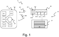
- An embodiment of home automation installation 11 or home automation network shown in FIG. figure 1 , comprises a motorized garage door 41 and a first embodiment of a control device, such as a wireless remote control 21, the motorized garage door device and the wireless remote control communicating by means of electromagnetic signals 71 issued by the remote control 21 and electromagnetic signals 81 emitted by the motorized garage door device 41.
- a control device such as a wireless remote control 21, the motorized garage door device and the wireless remote control communicating by means of electromagnetic signals 71 issued by the remote control 21 and electromagnetic signals 81 emitted by the motorized garage door device 41.
- the motorized garage door device 41 comprises an actuator 61 driving the door 51.
- the actuator 61 comprises an electric motor 615, emitting means 611 and receiving 612 electromagnetic signals, a logic processing unit 613 and means 614 for controlling the power supply of the electric motor.
- the processing logic unit 613 comprises a microprocessor and signal processing means or software means for interpreting a signal such as a command command received by the signal receiving means. This interpretation makes it possible to generate motor control signals which are transmitted to the motor power control means.
- the wireless remote control 21 comprises a power supply 213, a logic processing unit 212, electromagnetic signal receiving means 211, electromagnetic signal transmission means 214, a memory 215 in which are stored the various commands that can be issued in destination to the door actuator 61, and a man-machine interface 31 equipped with a display device (for example a screen or light-emitting diodes) able to display a symbol, representative of a type of order such as for example a up arrow to indicate a rise order, a square to indicate a stop command ...
- the logic processing unit 212 includes a microprocessor.
- the control device in particular the logical processing unit, comprises hardware means and software or processing means making it able to define the priorities between the different orders of commands that can be sent to the door actuator. 61 in order to choose the next command order to propose to the user. This order is displayed on the display device of the man-machine interface 31 before it is sent to the actuator 61.
- the priorities between the various possible control commands are determined for example according to the history of the orders previously sent, the state of the actuator, various information received from the actuator ....
- the user could also configure a sequence of order to execute, or customize the reactions of its product according to the state in which it is; for example, for a garage door having encountered an obstacle to the descent, and having stopped on this obstacle, the remote control will propose by default the sending of a climb order for the next order to be sent, whereas the In this case, the user could prefer to systematically send a descent order.
- the list of commands stored in the memory 215 is not fixed and can be updated during the lifetime of the product using a specific tool, or a more advanced remote control, or using any other means to enter into communication with the control device.
- This list of commands does not necessarily consist of simple commands only, it could also contain scenarios allowing to launch a succession of orders simple to at least one home automation equipment of the installation; For example, there could be a "I leave my home” scenario which, once selected and launched, could ask the garage door to close, the alarm to start, the shutters to close. , and the patio awning to fold back.
- Each scenario can be represented by a specific symbol (for example, the scenario "I leave my home” could be symbolized by a padlock, a scenario " fallen of the day” by a moon). If a list of predefined scenarios can be proposed to the user, this one also has the possibility to define his own scenarios and to modify those which are proposed to him by default.
- the signals 71 emitted by means of the electromagnetic signal emitting means 214 by the remote control comprise control commands of the motorized garage door device.
- the signals 81 emitted by means of the electromagnetic signal transmission means 611 by the motorized door device in the direction of the remote control may for example be informational signals, concerning, for example, the interpretation of the received control commands.
- This information may be, for example, information of good reception of the order of order, or information of good execution of this order, or on the contrary information of non execution of this order, the reason for this non-execution being able to be specified in this information.
- These signals 81 can on the other hand convey information relating to the state of the door.
- Examples of conditions of the motorized door are for example: the door is completely open, the door is completely closed, the door is in an intermediate position, the door opens, the door closes, an obstacle has been detected, the movement of the door has been reversed, the actuator is in a normal operating mode or the actuator is in an abnormal operating mode. Other states may be considered.
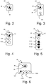
- the figure 2 illustrates a second embodiment of the control device 22, in which there is only one man-machine interface element 32 capable of displaying a symbol 92 representative of a control command proposed by the control device .
- a support on the element 32 allows a validation, this validation causing the triggering of the sending of this order.
- This single element can also make it possible to modify the proposed order thanks to a specific ergonomics linked to the element 32, before validating and triggering the sending of the command order.
- the user could for example proceed to a "short" support (of a duration less than 800ms for example) on the element 32, and to modify this order it could for example proceed to a "long" support (of a duration greater than 1.2s for example) on the element 32, each "long" support for displaying a different command (the commands can thus scroll in a loop).
- the figure 3 illustrates a third embodiment of the control device 23.
- This comprises a first human-machine interface element 33 provided with a display interface capable of displaying a symbol 93 representative of the proposed control order and a second element of human-machine interface 103.
- the element 33 serves only to display the proposed control order, and the element 103 allows the user, by an action on the to modify this order then to validate it. Validation automatically sends the order.
- the modification of the proposed order can be done for example by short-term supports, and its validation by a longer support, or vice versa.
- the element 33 can serve as a display and means of validation and then sending the selected order, the element 103 only allowing to modify the order proposed by the control device.
- the element 33 can serve as a display and means for modifying the proposed order, the element 103 only allowing to validate and then send the selected order.
- the element 33 is also a key.
- the figure 4 illustrates a fourth embodiment 24. It comprises a first human-machine interface element 34 adapted to display a symbol 94 representative of the proposed command, a second human-machine interface element 114 for modifying the proposed command and a third human-machine interface element 104 for triggering the sending of the selected command. Successive presses on the element 114 scroll the list of possible commands on the display element 34.
- the figure 5 illustrates a fifth embodiment 25. It comprises a display element 35 of a symbol 95 representative of the proposed command, human-machine interface elements 1151, 1152, 1153 for modifying the proposed command, and an element separate human-machine interface 105 to trigger the sending of the selected command. If the command displayed on the display element 35 is not suitable, it is sufficient to select the desired command directly using the elements 1151, 1152 and 1153. This embodiment is of particular interest if, depending on the duration of the presses on the keys 1151, 1152 and 1153, or according to an ergonomics of particular use of these keys (successive supports for example), orders of different natures are sent.
- a short press on the key 1152 will select a stop command while a long press will select the order "go to predefined position 1"
- a short press on the key 1151 will select a rising order then a long press will select the order "go to predefined position 2" ...
- the selection of the various orders is facilitated.
- the figure 6 illustrates a sixth embodiment 26.
- This device is a variant of that described on the figure 2 .
- the element 36 is able to perform the same functions as the element 32.
- the difference lies in the fact that the device 26 is able to control different equipment and the selection of the equipment that the user wishes to drive is done at the same time.
- selection elements 1261, 1262, 1263, and 1264 when the user has acted on the element 1261, as illustrated in the figure, the device will drive a first equipment, if it acted on the element 1262, it will drive a second equipment and so on.
- the list of possible commands may be different from one equipment to another.
- the list of possible commands could include climb or open, stop, descent or close commands.
- the second equipment is Venetian blind type, the list of possible commands could include the following commands: rise, stop, blade orientation, descent.
- Another equipment could be a portal for which the list of possible commands could include a partial opening command, a total opening command, a closing command ...
- devices 23, 24 and 25 could also present this type of selection interface to control multiple devices.
- the set of elements 32, 33, 34, 35, 36, as well as all the other elements of "button” type represented on the Figures 2 to 6 can be of "touch” technology. They can thus be virtual keys, or can be mounted on a moving mechanical button.
- At least one of the elements may be enriched with a capacitive type sensor for example, capable of detecting the approach of the hand of the user which allows to wake up the control device and to display the command only when the user is about to actually use his remote control.
- a capacitive type sensor for example, capable of detecting the approach of the hand of the user which allows to wake up the control device and to display the command only when the user is about to actually use his remote control.
- pressing on any one of the keys of the control device may wake up the device in standby.
- this support will have no function other than the alarm function.
- e-paper electronic paper
- electronic ink consuming energy only when it is changes state, the display is permanent, and there is no need to wake / sleep command point.
- the awakening of the control point can be done by simple handling or by a shaking movement or by any other specific movement of the control point; the selection of the commands in the list can also be done in this way (each jerk of the control point causes the selection of a new command in the list).
- the symbol representing the order that is displayed on the control point can be enriched by any other symbol, such as for example a representative symbol of the impact that the l the order proposed, if selected and sent to the home automation equipment, on the overall energy consumption of the house.
- a representative symbol of the impact that the l the order proposed, if selected and sent to the home automation equipment, on the overall energy consumption of the house For example, if the outside temperature is relatively low, and that the user selects an opening order of a window, it will be possible to display, in addition to the opening symbol, a symbol indicating that if this opening is confirmed, it will cause additional energy consumption.
- a note corresponding to the impact of an order on this consumption this note could be symbolized by 1 to 3 green stars to quantify any energy saving, and by 1 to 3 red stars to quantify a waste of energy. energy for example).
- the control device comprises hardware means and / or software or processing means for controlling its operation in accordance with the method of the invention, including governing the steps of this method and their sequences.
- the hardware means comprise the logical processing unit.
- the processing means may be contained in the logical processing unit.
- the processing means may in particular comprise a computer program code means adapted to performing the steps of the method according to the invention, when the program runs on a computer.
- the processing means comprise the means for selecting a possible command command from among a plurality of predefined command commands and which can be issued by the control device.
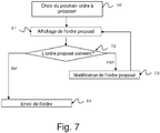
- the figure 7 is a flowchart illustrating the main steps of implementation of a first embodiment of the operating method according to the invention.
- an autonomous control device that is to say having its own energy source
- an awakening step must be implemented to end this waking state.
- This optional step is not represented and corresponds to the transition from the standby state of the remote control to a normal operating condition with optimum power supply.
- a wired control device that is to say, being connected to the power supply network of the building, it is the same. This awakening step can be performed in different ways, as described above.
- the remote control implements a step of selecting or selecting the next command to be proposed in a step E0.
- a second step E1 the control device displays the control command chosen by the control device.
- This command order is proposed to the user for the next order sending, and this, for a predefined time D0 not shown in the figure. Without any action on the part of the user during this time D0, the control device can automatically return to the standby state.
- a third step E2 the control device determines whether the proposed control command is suitable for the user. To do this, the control device analyzes an action of the user. If the command order is suitable, go directly to a step E4 in which the command order is sent. Otherwise, in a step E3, the control device modifies the proposed control order according to the actions of the user. Whenever the user modifies the proposed order, the symbol corresponding to the modified order is displayed, that is to say that loop on the step E1.
- step E4 the selected order is validated and sent to the home automation device with which the remote control is able to communicate, the sending can be done in different ways (communication by electromagnetic waves, infrared, wired connection. ..). Controlled home automation equipment can then initiate its action (for example movement).
- a first option is to put the remote control and put it back into its standby state.
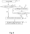
- Another option, possible for a bidirectional control device, is to implement a second embodiment of the operating method described below with reference to the flow chart of the figure 8 .
- This second embodiment comprises the steps E5 to E9 of the figure 8 in addition to the steps of the figure 7 .
- step E5 the nature of this order is determined in a step E5. If it is not a movement order, we can go directly to a step E8 in which the device chooses the next command order to propose to the user. If it is a movement order, we go to a step E6 in which, the control device chooses and displays for the duration of the movement, a stop order so that, in case of emergency, the user can validate and send this order quickly. The user has of course the possibility to modify this stop order and to choose any other order of order in the list of possible commands. If the user decides to send the proposed stop order or any other order of his choice, it returns to step E4 sending the order. Otherwise, once the movement is completed, we go to step E8.
- Step E8 consists in making the choice of the next command order that the device will propose to send to the home automation equipment, as in step E0.
- This new order can remain displayed on the display device for a predetermined duration D1 (step E9), this duration D1 can be parameterized, before the control device goes back to sleep, and this, so that the user can send this order rather quickly and restart the procedure directly in step E4, without going through the wake up step.
- the duration D1 the user has of course the possibility of modifying the proposed order.
- a unidirectional control device to implement a third embodiment of the operating method described below with reference to the flow chart of the figure 9 .
- This third embodiment comprises the steps E10 to E13 of the figure 9 in addition to the steps of the figure 7 .
- the unidirectional control device is not aware of the state of the equipment ordered, following the sending of the order made in step E4.
- a step E10 one can examine the nature of the order that has just been sent. If it is not a movement order, it is possible to go directly to the step E12 in which the device chooses the next command order to propose to the user. If it is a movement command, it goes to a step E11 in which the control device chooses and displays for a predetermined duration D2, this duration D2 can be parameterizable, a stop command for, in case of urgent, the user can validate and send this order quickly. The control device not being informed of the end of the movement, this time D2 will be chosen greater than a standard time of operation of the home automation equipment. Naturally, during this duration D2, the proposed order can be modified by the user who can immediately send the order he has chosen.
- step E4 sending the order.
- step E12 of choice of the next command order that the device proposes to send to the home automation equipment we proceed to step E12 of choice of the next command order that the device proposes to send to the home automation equipment, as in step E0.
- This new order can remain displayed on the display device for a predetermined duration D3 (step E13), before the control device goes back to standby, so that the user can send this order rather quickly and restart. the procedure directly in step E4, without going through the wake up step.
- the user has the possibility of modifying the proposed control order.
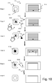
- the figure 10 illustrates an example of implementation of the operating method according to the invention described by the figures 7 and 8 .
- the home automation network 110 uses a bidirectional wireless remote control 210, equipped with a single button 310 equipped with a display device, and able to communicate with a motorized garage door 510.
- Step 1 shows the installation at rest, in a waiting state for a next command.
- the door 510 is stationary, in the closed position, the remote control 210 emits no signal, it is in standby mode, the button 310 does not display any information.
- Step 2 illustrates the approach of the hand of the user near the button of the remote control 210; this approach causes the awakening of the remote control 210, the first reaction is to ask the door what is its real state in a frame 7101; the door responds that it is completely closed in its response frame 8101, and the remote control can then display on the button 310, a representative element 9101 of the order that the remote control 210 proposes to send to the door 510. In this example, it is a climb order symbolized by an upward arrow.
- the user validates, for example by briefly pressing the button 310, the proposed order represented by the element 9101, and the remote control 210 then transmits a control frame 7102 containing the validated command to the gate 510.
- the door starts moving until reaching its high stop as illustrated in step 4.
- the remote control can optionally display a stop command symbolized by a solid square 9102 so that the user can quickly intervene if necessary.
- the remote control can inform the remote control by sending it an 8102 feedback frame, as shown in step 5.
- the remote control can then choose the next command it will propose to the user for a predetermined duration D1, in the example, the remote control chooses the descent order symbolized by a arrow 9103 facing downwards; it could also "go back to sleep” immediately, to display the next order only the next time it detects the approach of the user's hand or when the user presses the button 310 in case the remote control is not equipped with means for detecting the approach of the hand of the user.
- the remote control 210 returns to a state of rest in which no more order is displayed (step 6).
- the figure 11 illustrates an example of implementation of the operating method according to the invention described by the figures 7 and 9 .
- the home automation network 111 uses a wireless remote control 211 unidirectional, with a single button 311 equipped with a display device, able to communicate with a motorized garage door 511.
- Steps 1, 2 and 3 are identical to steps 1, 2, and 3 described on the figure 10 .
- the remote control is unidirectional, and therefore, it can not receive an information frame from the gate indicating that the required movement or action is complete.
- the optional step 4 consists in proposing to the user a stop command symbolized by an element 9112 for a predefined duration D2.
- the remote control can then choose the next command order it will propose to the user for a predetermined duration D3; in the example, the remote control chooses the descent order 9113; it could also "go back to sleep” immediately, to display the next order only the next time it detects the approach of the user's hand or when the user presses button 310 in case the remote control is not equipped with means for detecting the approach of the user's hand.
- the remote control 210 returns to a state of rest in which no more order is displayed (step 6).
- control means means a step of selecting at least one possible command command from among a plurality of predefined command commands, issuable by the controller and at least one display step of the at least one order selected by this control device ".
- the method preferably comprises the selection of a single order and the display of this single order, which advantageously allows the use of a display interface of reduced size while allowing to display a symbol of sufficiently large size large, to facilitate its understanding by the user.
- the order (s) selected do not include all the command commands that can be executed by the home automation equipment, in particular not all the commands that can be executed by the home automation equipment, given the state of the home automation equipment.
- the selected order (s) include the most relevant order (s) to be executed based on the current state of the home automation equipment or the order (s) that are most likely to be executed given the current status of the building. home automation equipment.
- the order or orders selected are among orders that are executable by the home automation equipment and relevant to the actuator.
- the command order of this action is not selected (no need to effect, a priori, to order this action again).
- the actions that can not be performed by the home automation equipment given its state for example a climb order will not be selected by the control device if the equipment is already positioned in high abutment.
- an order of interruption of an action can be selected during the execution of the action.
- control device is capable, for example, of controlling a blind with steerable blades in a first mode of operation, and a garage door in a second mode of operation, it knows among other things, orientation orders. of blades. If the garage door is in the process of being ordered, that is to say that the second mode of operation has been previously selected by the user, the selected order should not concern the blind, in particular not the orientation of the awning blades. Thus, if the control device is capable of controlling several home automation equipment in different operating modes, the order or orders selected by the control device concern only the home automation equipment controlled in the operating mode selected by the user.
- the selection of at least one order is performed by the control device itself.
- the display of a command order can be achieved by displaying, on a screen, a symbol associated with a command button of this order or by displaying, on a touch screen, a symbol constituting a command button of this order.
Landscapes
- Engineering & Computer Science (AREA)
- Automation & Control Theory (AREA)
- Computer Networks & Wireless Communication (AREA)
- Signal Processing (AREA)
- Human Computer Interaction (AREA)
- Physics & Mathematics (AREA)
- General Physics & Mathematics (AREA)
- Selective Calling Equipment (AREA)
Applications Claiming Priority (1)
| Application Number | Priority Date | Filing Date | Title |
|---|---|---|---|
| FR1151589A FR2972062B1 (fr) | 2011-02-28 | 2011-02-28 | Dispositif de commande comprenant une interface capable de proposer le prochain ordre de commande a transmettre a un equipement domotique |
Publications (2)
| Publication Number | Publication Date |
|---|---|
| EP2492884A1 true EP2492884A1 (de) | 2012-08-29 |
| EP2492884B1 EP2492884B1 (de) | 2017-11-29 |
Family
ID=44146242
Family Applications (1)
| Application Number | Title | Priority Date | Filing Date |
|---|---|---|---|
| EP12157131.9A Active EP2492884B1 (de) | 2011-02-28 | 2012-02-27 | Steuervorrichtung, die eine schnittstelle umfasst, die in der lage ist, den nächsten befehl an ein haushaltsgerät vorzuschlagen |
Country Status (4)
| Country | Link |
|---|---|
| US (1) | US8972030B2 (de) |
| EP (1) | EP2492884B1 (de) |
| CN (1) | CN102650853B (de) |
| FR (1) | FR2972062B1 (de) |
Cited By (1)
| Publication number | Priority date | Publication date | Assignee | Title |
|---|---|---|---|---|
| WO2016022847A1 (en) * | 2014-08-06 | 2016-02-11 | Lutron Electronics Co., Inc. | Motorized window treatment monitoring and control |
Families Citing this family (8)
| Publication number | Priority date | Publication date | Assignee | Title |
|---|---|---|---|---|
| US9625884B1 (en) * | 2013-06-10 | 2017-04-18 | Timothy Harris Ousley | Apparatus for extending control and methods thereof |
| DE102013112558A1 (de) * | 2013-11-14 | 2015-05-21 | Eaton Electrical Ip Gmbh & Co. Kg | Energiegewinnungssteuervorrichtung, System aus einer Energiegewinnungssteuervorrichtung und einer Empfangseinrichtung sowie Verfahren zur Steuerung einer Empfangseinrichtung durch eine Energiegewinnungssteuervorrichtung |
| US9860076B2 (en) | 2014-05-07 | 2018-01-02 | Vivint, Inc. | Home automation via voice control |
| FR3024783B1 (fr) * | 2014-08-11 | 2017-07-21 | Somfy Sas | Configuration securisee d'une installation domotique |
| EP3113139A1 (de) * | 2015-06-30 | 2017-01-04 | Orange | Aktualisierung ehemaliger befehle zur steuerung einer entfernten elektronischen vorrichtung |
| DE102016111867A1 (de) * | 2016-06-29 | 2018-01-04 | Insta Gmbh | Verfahren zum Betreiben eines batteriebetriebenen Bediengerätes sowie batteriebetriebenes Bediengerät |
| US10741060B2 (en) * | 2017-12-05 | 2020-08-11 | Bose Corporation | Context-sensitive remote control device |
| JP6989647B2 (ja) * | 2018-07-12 | 2022-01-05 | 三菱電機株式会社 | 遠隔操作システム及び機器管理方法 |
Citations (3)
| Publication number | Priority date | Publication date | Assignee | Title |
|---|---|---|---|---|
| US20040268391A1 (en) | 2003-06-25 | 2004-12-30 | Universal Electronics Inc. | Remote control with selective key illumination |
| US20060050142A1 (en) | 2004-09-08 | 2006-03-09 | Universal Electronics Inc. | Configurable controlling device having an associated editing program |
| EP1783716A1 (de) | 2005-11-04 | 2007-05-09 | Somfy SAS | Verfahren zum Betrieb eines Gebäudenetzes, das eine Zeichengabeschnittstelle umfasst |
Family Cites Families (22)
| Publication number | Priority date | Publication date | Assignee | Title |
|---|---|---|---|---|
| US5086385A (en) * | 1989-01-31 | 1992-02-04 | Custom Command Systems | Expandable home automation system |
| KR0128169B1 (ko) * | 1993-12-31 | 1998-04-15 | 김광호 | 사용자 제어 정의 기능을 가지는 가정 자동화 시스템 |
| US6192282B1 (en) * | 1996-10-01 | 2001-02-20 | Intelihome, Inc. | Method and apparatus for improved building automation |
| JP3612696B2 (ja) * | 1996-12-18 | 2005-01-19 | ソニー株式会社 | 情報処理装置および方法、並びにリモートコントロールシステム |
| JP3363063B2 (ja) * | 1997-05-06 | 2003-01-07 | 株式会社日立製作所 | プラント制御システム及びプロセスコントローラ |
| US7831930B2 (en) * | 2001-11-20 | 2010-11-09 | Universal Electronics Inc. | System and method for displaying a user interface for a remote control application |
| US6756998B1 (en) * | 2000-10-19 | 2004-06-29 | Destiny Networks, Inc. | User interface and method for home automation system |
| US6938101B2 (en) * | 2001-01-29 | 2005-08-30 | Universal Electronics Inc. | Hand held device having a browser application |
| US7092772B2 (en) * | 2002-04-17 | 2006-08-15 | Black & Decker Inc. | Home automation system |
| US7005979B2 (en) * | 2003-06-25 | 2006-02-28 | Universal Electronics Inc. | System and method for monitoring remote control transmissions |
| US6967565B2 (en) * | 2003-06-27 | 2005-11-22 | Hx Lifespace, Inc. | Building automation system |
| KR100546674B1 (ko) * | 2003-11-05 | 2006-01-26 | 엘지전자 주식회사 | 통합 리모컨 구현장치 및 그 방법 |
| US20050219210A1 (en) * | 2004-03-31 | 2005-10-06 | The Neil Squire Society | Pointer interface for handheld devices |
| US20060161856A1 (en) * | 2005-01-20 | 2006-07-20 | International Business Machines Corporation | Data collection tool for a computer |
| US7831321B2 (en) * | 2005-06-09 | 2010-11-09 | Whirlpool Corporation | Appliance and accessory for controlling a cycle of operation |
| FR2897186B1 (fr) * | 2006-02-06 | 2008-05-09 | Somfy Sas | Procede de communication par relais entre une telecommande nomade et des equipements domotiques. |
| CN101135903B (zh) * | 2006-09-01 | 2012-05-30 | 海尔集团公司 | 一种电器远程控制系统 |
| JP5280665B2 (ja) * | 2007-10-26 | 2013-09-04 | オークマ株式会社 | 手動シフト操作機能を備えた数値制御装置 |
| CN101158867A (zh) * | 2007-10-26 | 2008-04-09 | 海信集团有限公司 | 家电设备的远程控制方法及能够控制家电设备的报警器 |
| CN101169650A (zh) * | 2007-11-20 | 2008-04-30 | 暨南大学 | 远程网络家电控制系统及其控制方法 |
| US8543244B2 (en) * | 2008-12-19 | 2013-09-24 | Oliver Joe Keeling | Heating and cooling control methods and systems |
| WO2011070734A1 (ja) * | 2009-12-07 | 2011-06-16 | パナソニック株式会社 | フォーマット変換サーバー、再生装置及び情報再生システム |
-
2011
- 2011-02-28 FR FR1151589A patent/FR2972062B1/fr not_active Expired - Fee Related
-
2012
- 2012-02-27 EP EP12157131.9A patent/EP2492884B1/de active Active
- 2012-02-28 US US13/407,276 patent/US8972030B2/en not_active Expired - Fee Related
- 2012-02-28 CN CN201210048179.9A patent/CN102650853B/zh not_active Expired - Fee Related
Patent Citations (3)
| Publication number | Priority date | Publication date | Assignee | Title |
|---|---|---|---|---|
| US20040268391A1 (en) | 2003-06-25 | 2004-12-30 | Universal Electronics Inc. | Remote control with selective key illumination |
| US20060050142A1 (en) | 2004-09-08 | 2006-03-09 | Universal Electronics Inc. | Configurable controlling device having an associated editing program |
| EP1783716A1 (de) | 2005-11-04 | 2007-05-09 | Somfy SAS | Verfahren zum Betrieb eines Gebäudenetzes, das eine Zeichengabeschnittstelle umfasst |
Cited By (6)
| Publication number | Priority date | Publication date | Assignee | Title |
|---|---|---|---|---|
| WO2016022847A1 (en) * | 2014-08-06 | 2016-02-11 | Lutron Electronics Co., Inc. | Motorized window treatment monitoring and control |
| US10139791B2 (en) | 2014-08-06 | 2018-11-27 | Lutron Electronics Co., Inc. | Motorized window treatment monitoring and control |
| US10691086B2 (en) | 2014-08-06 | 2020-06-23 | Lutron Technology Company Llc | Motorized window treatment monitoring and control |
| US11378925B2 (en) | 2014-08-06 | 2022-07-05 | Lutron Technology Company Llc | Motorized window treatment monitoring and control |
| US11681263B2 (en) | 2014-08-06 | 2023-06-20 | Lutron Technology Company Llc | Motorized window treatment monitoring and control |
| US12085906B2 (en) | 2014-08-06 | 2024-09-10 | Lutron Technology Company Llc | Motorized window treatment monitoring and control |
Also Published As
| Publication number | Publication date |
|---|---|
| EP2492884B1 (de) | 2017-11-29 |
| CN102650853B (zh) | 2017-10-24 |
| FR2972062A1 (fr) | 2012-08-31 |
| CN102650853A (zh) | 2012-08-29 |
| US20120253483A1 (en) | 2012-10-04 |
| US8972030B2 (en) | 2015-03-03 |
| FR2972062B1 (fr) | 2013-04-12 |
Similar Documents
| Publication | Publication Date | Title |
|---|---|---|
| EP2492884B1 (de) | Steuervorrichtung, die eine schnittstelle umfasst, die in der lage ist, den nächsten befehl an ein haushaltsgerät vorzuschlagen | |
| EP2009527B1 (de) | Konfigurationsverfahren eines Antriebssystems eines Verschlussschirms, der als Sonnenschutz oder Projektionsschirm fungieren kann | |
| EP2130100B1 (de) | Verfahren zum konfigurieren einer hausautomatisierungsinstallation und werkzeug zu seiner implementierung | |
| EP2983049B1 (de) | Betriebsverfahren einer steuervorrichtung einer heiminstallation eines gebäudes, und entsprechende steuervorrichtung | |
| EP2362368B1 (de) | Szenariozuteilung zu Steuertasten | |
| EP2593626A1 (de) | Betriebsverfahren für eine vorrichtung mit einem elektromechanischen aktor zur steuerung eines beweglichen veschluss- oder sperrelements für eine öffnung eines gebäudes | |
| EP2387016B1 (de) | Method for positioning a unit for controlling an actuator for operating a window-covering element | |
| EP2000867A1 (de) | Verfahren zur Konfiguration einer Hausgeräteanlage, die auf klimatische Ereignisse reagiert | |
| EP3205810B2 (de) | Gerät zur fernsteuerung von vorrichtungen zum verschluss von gebäudeöffnungen vom typ jalousie oder klappladen | |
| EP2725182B1 (de) | Funktionsverfahren eines Betätigungsstellglieds eines beweglichen Elements einer Haustechnikanlage, und Stellglied, das nach diesem Verfahren funktioniert | |
| EP2109086B1 (de) | Autonomer Befehlsgeber für Heimanlage | |
| FR2916870A1 (fr) | Systeme d'interface homme/machine notamment pour installation domotique | |
| EP3073335B1 (de) | Verfahren zur steuerung einer hausanlage eines gebäudes, und entsprechende steuervorrichtung | |
| EP2958093B1 (de) | Funktionsverfahren einer steuervorrichtung, die eine änderung einer angezeigten grafischen darstellung in abhängigkeit von einem ausgewählten parameter ermöglicht | |
| EP2656190B1 (de) | Vorrichtung sowie verfahren zur steuerung einer motorisch angetriebenen mobilen blende mit verstellbaren lamellen | |
| EP2838074B1 (de) | Haustechnik-Fernbedienung, Element zum Empfangen von Haustechnik-Befehlen, und Betriebsverfahren einer solchen Fernbedienung und eines solchen Empfängers von Befehlen | |
| EP1488294A1 (de) | Verfahren zur steuerung einer walzenblende oder ähnlichem | |
| EP1884848A1 (de) | Verfahren zur Datenänderung eines unabhängigen Kontrollsystems für einen Rollladen | |
| KR102201729B1 (ko) | 디스플레이 장치 | |
| EP3114553A1 (de) | Verfahren zur konfiguration einer vorrichtung zur steuerung einer heimautomatisierungsanlage eines gebäudes und der umgebung des gebäudes und zugehörige steuerungsvorrichtung | |
| WO2014177526A2 (fr) | Unite de gestion et/ou de commande d'une installation domotique et procede de fonctionnement d'une telle unite de gestion et/ou de commande |
Legal Events
| Date | Code | Title | Description |
|---|---|---|---|
| PUAI | Public reference made under article 153(3) epc to a published international application that has entered the european phase |
Free format text: ORIGINAL CODE: 0009012 |
|
| AK | Designated contracting states |
Kind code of ref document: A1 Designated state(s): AL AT BE BG CH CY CZ DE DK EE ES FI FR GB GR HR HU IE IS IT LI LT LU LV MC MK MT NL NO PL PT RO RS SE SI SK SM TR |
|
| AX | Request for extension of the european patent |
Extension state: BA ME |
|
| 17P | Request for examination filed |
Effective date: 20130228 |
|
| 17Q | First examination report despatched |
Effective date: 20130410 |
|
| GRAP | Despatch of communication of intention to grant a patent |
Free format text: ORIGINAL CODE: EPIDOSNIGR1 |
|
| INTG | Intention to grant announced |
Effective date: 20170608 |
|
| GRAS | Grant fee paid |
Free format text: ORIGINAL CODE: EPIDOSNIGR3 |
|
| GRAJ | Information related to disapproval of communication of intention to grant by the applicant or resumption of examination proceedings by the epo deleted |
Free format text: ORIGINAL CODE: EPIDOSDIGR1 |
|
| GRAL | Information related to payment of fee for publishing/printing deleted |
Free format text: ORIGINAL CODE: EPIDOSDIGR3 |
|
| GRAR | Information related to intention to grant a patent recorded |
Free format text: ORIGINAL CODE: EPIDOSNIGR71 |
|
| GRAA | (expected) grant |
Free format text: ORIGINAL CODE: 0009210 |
|
| INTC | Intention to grant announced (deleted) | ||
| RAP1 | Party data changed (applicant data changed or rights of an application transferred) |
Owner name: SOMFY ACTIVITES SA |
|
| AK | Designated contracting states |
Kind code of ref document: B1 Designated state(s): AL AT BE BG CH CY CZ DE DK EE ES FI FR GB GR HR HU IE IS IT LI LT LU LV MC MK MT NL NO PL PT RO RS SE SI SK SM TR |
|
| INTG | Intention to grant announced |
Effective date: 20171020 |
|
| REG | Reference to a national code |
Ref country code: CH Ref legal event code: EP |
|
| REG | Reference to a national code |
Ref country code: AT Ref legal event code: REF Ref document number: 951057 Country of ref document: AT Kind code of ref document: T Effective date: 20171215 |
|
| REG | Reference to a national code |
Ref country code: IE Ref legal event code: FG4D Free format text: LANGUAGE OF EP DOCUMENT: FRENCH |
|
| REG | Reference to a national code |
Ref country code: DE Ref legal event code: R096 Ref document number: 602012040251 Country of ref document: DE |
|
| REG | Reference to a national code |
Ref country code: FR Ref legal event code: PLFP Year of fee payment: 7 |
|
| REG | Reference to a national code |
Ref country code: NL Ref legal event code: MP Effective date: 20171129 |
|
| REG | Reference to a national code |
Ref country code: LT Ref legal event code: MG4D |
|
| REG | Reference to a national code |
Ref country code: AT Ref legal event code: MK05 Ref document number: 951057 Country of ref document: AT Kind code of ref document: T Effective date: 20171129 |
|
| PG25 | Lapsed in a contracting state [announced via postgrant information from national office to epo] |
Ref country code: NO Free format text: LAPSE BECAUSE OF FAILURE TO SUBMIT A TRANSLATION OF THE DESCRIPTION OR TO PAY THE FEE WITHIN THE PRESCRIBED TIME-LIMIT Effective date: 20180228 Ref country code: ES Free format text: LAPSE BECAUSE OF FAILURE TO SUBMIT A TRANSLATION OF THE DESCRIPTION OR TO PAY THE FEE WITHIN THE PRESCRIBED TIME-LIMIT Effective date: 20171129 Ref country code: LT Free format text: LAPSE BECAUSE OF FAILURE TO SUBMIT A TRANSLATION OF THE DESCRIPTION OR TO PAY THE FEE WITHIN THE PRESCRIBED TIME-LIMIT Effective date: 20171129 Ref country code: FI Free format text: LAPSE BECAUSE OF FAILURE TO SUBMIT A TRANSLATION OF THE DESCRIPTION OR TO PAY THE FEE WITHIN THE PRESCRIBED TIME-LIMIT Effective date: 20171129 Ref country code: SE Free format text: LAPSE BECAUSE OF FAILURE TO SUBMIT A TRANSLATION OF THE DESCRIPTION OR TO PAY THE FEE WITHIN THE PRESCRIBED TIME-LIMIT Effective date: 20171129 |
|
| PG25 | Lapsed in a contracting state [announced via postgrant information from national office to epo] |
Ref country code: RS Free format text: LAPSE BECAUSE OF FAILURE TO SUBMIT A TRANSLATION OF THE DESCRIPTION OR TO PAY THE FEE WITHIN THE PRESCRIBED TIME-LIMIT Effective date: 20171129 Ref country code: BG Free format text: LAPSE BECAUSE OF FAILURE TO SUBMIT A TRANSLATION OF THE DESCRIPTION OR TO PAY THE FEE WITHIN THE PRESCRIBED TIME-LIMIT Effective date: 20180228 Ref country code: GR Free format text: LAPSE BECAUSE OF FAILURE TO SUBMIT A TRANSLATION OF THE DESCRIPTION OR TO PAY THE FEE WITHIN THE PRESCRIBED TIME-LIMIT Effective date: 20180301 Ref country code: AT Free format text: LAPSE BECAUSE OF FAILURE TO SUBMIT A TRANSLATION OF THE DESCRIPTION OR TO PAY THE FEE WITHIN THE PRESCRIBED TIME-LIMIT Effective date: 20171129 Ref country code: LV Free format text: LAPSE BECAUSE OF FAILURE TO SUBMIT A TRANSLATION OF THE DESCRIPTION OR TO PAY THE FEE WITHIN THE PRESCRIBED TIME-LIMIT Effective date: 20171129 Ref country code: HR Free format text: LAPSE BECAUSE OF FAILURE TO SUBMIT A TRANSLATION OF THE DESCRIPTION OR TO PAY THE FEE WITHIN THE PRESCRIBED TIME-LIMIT Effective date: 20171129 |
|
| PG25 | Lapsed in a contracting state [announced via postgrant information from national office to epo] |
Ref country code: NL Free format text: LAPSE BECAUSE OF FAILURE TO SUBMIT A TRANSLATION OF THE DESCRIPTION OR TO PAY THE FEE WITHIN THE PRESCRIBED TIME-LIMIT Effective date: 20171129 |
|
| PG25 | Lapsed in a contracting state [announced via postgrant information from national office to epo] |
Ref country code: CZ Free format text: LAPSE BECAUSE OF FAILURE TO SUBMIT A TRANSLATION OF THE DESCRIPTION OR TO PAY THE FEE WITHIN THE PRESCRIBED TIME-LIMIT Effective date: 20171129 Ref country code: CY Free format text: LAPSE BECAUSE OF FAILURE TO SUBMIT A TRANSLATION OF THE DESCRIPTION OR TO PAY THE FEE WITHIN THE PRESCRIBED TIME-LIMIT Effective date: 20171129 Ref country code: EE Free format text: LAPSE BECAUSE OF FAILURE TO SUBMIT A TRANSLATION OF THE DESCRIPTION OR TO PAY THE FEE WITHIN THE PRESCRIBED TIME-LIMIT Effective date: 20171129 Ref country code: DK Free format text: LAPSE BECAUSE OF FAILURE TO SUBMIT A TRANSLATION OF THE DESCRIPTION OR TO PAY THE FEE WITHIN THE PRESCRIBED TIME-LIMIT Effective date: 20171129 Ref country code: SK Free format text: LAPSE BECAUSE OF FAILURE TO SUBMIT A TRANSLATION OF THE DESCRIPTION OR TO PAY THE FEE WITHIN THE PRESCRIBED TIME-LIMIT Effective date: 20171129 |
|
| REG | Reference to a national code |
Ref country code: DE Ref legal event code: R097 Ref document number: 602012040251 Country of ref document: DE |
|
| PG25 | Lapsed in a contracting state [announced via postgrant information from national office to epo] |
Ref country code: RO Free format text: LAPSE BECAUSE OF FAILURE TO SUBMIT A TRANSLATION OF THE DESCRIPTION OR TO PAY THE FEE WITHIN THE PRESCRIBED TIME-LIMIT Effective date: 20171129 Ref country code: PL Free format text: LAPSE BECAUSE OF FAILURE TO SUBMIT A TRANSLATION OF THE DESCRIPTION OR TO PAY THE FEE WITHIN THE PRESCRIBED TIME-LIMIT Effective date: 20171129 Ref country code: SM Free format text: LAPSE BECAUSE OF FAILURE TO SUBMIT A TRANSLATION OF THE DESCRIPTION OR TO PAY THE FEE WITHIN THE PRESCRIBED TIME-LIMIT Effective date: 20171129 Ref country code: IT Free format text: LAPSE BECAUSE OF FAILURE TO SUBMIT A TRANSLATION OF THE DESCRIPTION OR TO PAY THE FEE WITHIN THE PRESCRIBED TIME-LIMIT Effective date: 20171129 |
|
| REG | Reference to a national code |
Ref country code: CH Ref legal event code: PL |
|
| PG25 | Lapsed in a contracting state [announced via postgrant information from national office to epo] |
Ref country code: MT Free format text: LAPSE BECAUSE OF FAILURE TO SUBMIT A TRANSLATION OF THE DESCRIPTION OR TO PAY THE FEE WITHIN THE PRESCRIBED TIME-LIMIT Effective date: 20171129 Ref country code: MC Free format text: LAPSE BECAUSE OF FAILURE TO SUBMIT A TRANSLATION OF THE DESCRIPTION OR TO PAY THE FEE WITHIN THE PRESCRIBED TIME-LIMIT Effective date: 20171129 |
|
| PLBE | No opposition filed within time limit |
Free format text: ORIGINAL CODE: 0009261 |
|
| STAA | Information on the status of an ep patent application or granted ep patent |
Free format text: STATUS: NO OPPOSITION FILED WITHIN TIME LIMIT |
|
| GBPC | Gb: european patent ceased through non-payment of renewal fee |
Effective date: 20180228 |
|
| 26N | No opposition filed |
Effective date: 20180830 |
|
| REG | Reference to a national code |
Ref country code: IE Ref legal event code: MM4A |
|
| REG | Reference to a national code |
Ref country code: BE Ref legal event code: MM Effective date: 20180228 |
|
| PG25 | Lapsed in a contracting state [announced via postgrant information from national office to epo] |
Ref country code: CH Free format text: LAPSE BECAUSE OF NON-PAYMENT OF DUE FEES Effective date: 20180228 Ref country code: LI Free format text: LAPSE BECAUSE OF NON-PAYMENT OF DUE FEES Effective date: 20180228 Ref country code: LU Free format text: LAPSE BECAUSE OF NON-PAYMENT OF DUE FEES Effective date: 20180227 Ref country code: SI Free format text: LAPSE BECAUSE OF FAILURE TO SUBMIT A TRANSLATION OF THE DESCRIPTION OR TO PAY THE FEE WITHIN THE PRESCRIBED TIME-LIMIT Effective date: 20171129 |
|
| PG25 | Lapsed in a contracting state [announced via postgrant information from national office to epo] |
Ref country code: IE Free format text: LAPSE BECAUSE OF NON-PAYMENT OF DUE FEES Effective date: 20180227 |
|
| PG25 | Lapsed in a contracting state [announced via postgrant information from national office to epo] |
Ref country code: BE Free format text: LAPSE BECAUSE OF NON-PAYMENT OF DUE FEES Effective date: 20180228 Ref country code: GB Free format text: LAPSE BECAUSE OF NON-PAYMENT OF DUE FEES Effective date: 20180228 |
|
| PG25 | Lapsed in a contracting state [announced via postgrant information from national office to epo] |
Ref country code: TR Free format text: LAPSE BECAUSE OF FAILURE TO SUBMIT A TRANSLATION OF THE DESCRIPTION OR TO PAY THE FEE WITHIN THE PRESCRIBED TIME-LIMIT Effective date: 20171129 |
|
| PG25 | Lapsed in a contracting state [announced via postgrant information from national office to epo] |
Ref country code: PT Free format text: LAPSE BECAUSE OF FAILURE TO SUBMIT A TRANSLATION OF THE DESCRIPTION OR TO PAY THE FEE WITHIN THE PRESCRIBED TIME-LIMIT Effective date: 20171129 Ref country code: HU Free format text: LAPSE BECAUSE OF FAILURE TO SUBMIT A TRANSLATION OF THE DESCRIPTION OR TO PAY THE FEE WITHIN THE PRESCRIBED TIME-LIMIT; INVALID AB INITIO Effective date: 20120227 |
|
| PG25 | Lapsed in a contracting state [announced via postgrant information from national office to epo] |
Ref country code: MK Free format text: LAPSE BECAUSE OF NON-PAYMENT OF DUE FEES Effective date: 20171129 |
|
| PG25 | Lapsed in a contracting state [announced via postgrant information from national office to epo] |
Ref country code: AL Free format text: LAPSE BECAUSE OF FAILURE TO SUBMIT A TRANSLATION OF THE DESCRIPTION OR TO PAY THE FEE WITHIN THE PRESCRIBED TIME-LIMIT Effective date: 20171129 Ref country code: IS Free format text: LAPSE BECAUSE OF FAILURE TO SUBMIT A TRANSLATION OF THE DESCRIPTION OR TO PAY THE FEE WITHIN THE PRESCRIBED TIME-LIMIT Effective date: 20180329 |
|
| PGFP | Annual fee paid to national office [announced via postgrant information from national office to epo] |
Ref country code: DE Payment date: 20230207 Year of fee payment: 12 |
|
| REG | Reference to a national code |
Ref country code: DE Ref legal event code: R119 Ref document number: 602012040251 Country of ref document: DE |
|
| PG25 | Lapsed in a contracting state [announced via postgrant information from national office to epo] |
Ref country code: DE Free format text: LAPSE BECAUSE OF NON-PAYMENT OF DUE FEES Effective date: 20240903 |
|
| PG25 | Lapsed in a contracting state [announced via postgrant information from national office to epo] |
Ref country code: DE Free format text: LAPSE BECAUSE OF NON-PAYMENT OF DUE FEES Effective date: 20240903 |
|
| PGFP | Annual fee paid to national office [announced via postgrant information from national office to epo] |
Ref country code: FR Payment date: 20251219 Year of fee payment: 15 |