EP2492740A2 - Lentille progressive et procédé pour la conception de lentille progressive - Google Patents
Lentille progressive et procédé pour la conception de lentille progressive Download PDFInfo
- Publication number
- EP2492740A2 EP2492740A2 EP12156484A EP12156484A EP2492740A2 EP 2492740 A2 EP2492740 A2 EP 2492740A2 EP 12156484 A EP12156484 A EP 12156484A EP 12156484 A EP12156484 A EP 12156484A EP 2492740 A2 EP2492740 A2 EP 2492740A2
- Authority
- EP
- European Patent Office
- Prior art keywords
- region
- progressive
- curvature
- power
- power lens
- Prior art date
- Legal status (The legal status is an assumption and is not a legal conclusion. Google has not performed a legal analysis and makes no representation as to the accuracy of the status listed.)
- Granted
Links
- 238000000034 method Methods 0.000 title claims description 20
- 230000000750 progressive effect Effects 0.000 title description 26
- 230000000052 comparative effect Effects 0.000 description 31
- 238000009826 distribution Methods 0.000 description 20
- 239000011159 matrix material Substances 0.000 description 12
- 230000007423 decrease Effects 0.000 description 11
- 210000001508 eye Anatomy 0.000 description 10
- 210000003128 head Anatomy 0.000 description 10
- 230000004462 vestibulo-ocular reflex Effects 0.000 description 9
- 201000009310 astigmatism Diseases 0.000 description 8
- 238000004519 manufacturing process Methods 0.000 description 8
- 210000005252 bulbus oculi Anatomy 0.000 description 7
- 230000008859 change Effects 0.000 description 7
- 230000014509 gene expression Effects 0.000 description 5
- 210000001525 retina Anatomy 0.000 description 5
- 208000001491 myopia Diseases 0.000 description 4
- 230000001447 compensatory effect Effects 0.000 description 2
- 238000010586 diagram Methods 0.000 description 2
- 238000005516 engineering process Methods 0.000 description 2
- 230000004424 eye movement Effects 0.000 description 2
- 230000011514 reflex Effects 0.000 description 2
- 210000000887 face Anatomy 0.000 description 1
- 238000003384 imaging method Methods 0.000 description 1
- 230000006872 improvement Effects 0.000 description 1
- 239000000463 material Substances 0.000 description 1
- 230000005499 meniscus Effects 0.000 description 1
- 210000003205 muscle Anatomy 0.000 description 1
- 230000007230 neural mechanism Effects 0.000 description 1
- 230000003287 optical effect Effects 0.000 description 1
- 201000010041 presbyopia Diseases 0.000 description 1
- 230000008569 process Effects 0.000 description 1
- 210000002480 semicircular canal Anatomy 0.000 description 1
- 230000001960 triggered effect Effects 0.000 description 1
Images


Classifications
-
- G—PHYSICS
- G02—OPTICS
- G02C—SPECTACLES; SUNGLASSES OR GOGGLES INSOFAR AS THEY HAVE THE SAME FEATURES AS SPECTACLES; CONTACT LENSES
- G02C7/00—Optical parts
- G02C7/02—Lenses; Lens systems ; Methods of designing lenses
- G02C7/06—Lenses; Lens systems ; Methods of designing lenses bifocal; multifocal ; progressive
- G02C7/061—Spectacle lenses with progressively varying focal power
- G02C7/068—Special properties achieved by the combination of the front and back surfaces
-
- G—PHYSICS
- G02—OPTICS
- G02C—SPECTACLES; SUNGLASSES OR GOGGLES INSOFAR AS THEY HAVE THE SAME FEATURES AS SPECTACLES; CONTACT LENSES
- G02C7/00—Optical parts
- G02C7/02—Lenses; Lens systems ; Methods of designing lenses
- G02C7/024—Methods of designing ophthalmic lenses
- G02C7/027—Methods of designing ophthalmic lenses considering wearer's parameters
-
- G—PHYSICS
- G02—OPTICS
- G02C—SPECTACLES; SUNGLASSES OR GOGGLES INSOFAR AS THEY HAVE THE SAME FEATURES AS SPECTACLES; CONTACT LENSES
- G02C2202/00—Generic optical aspects applicable to one or more of the subgroups of G02C7/00
- G02C2202/08—Series of lenses, lens blanks
Definitions
- the present invention relates to a progressive-power lens and a method for designing a progressive-power lens.
- An aspect of the invention is directed to a progressive-power lens including an eyeball-side surface which includes a distance portion and a near portion having different values of dioptric power and an intermediate portion that connects the distance portion and the near portion to each other.
- An object-side surface of the progressive-power lens includes a first region extending along a principal meridian and having a spherical shape having first curvature, a second region facing the distance portion and having a spherical shape having second curvature equal to the first curvature, and a third region located outside the first region and below the second region and having third curvature greater than the first curvature.
- the object-side surface in which the eyeball-side surface (inner surface) includes a distance portions, a near portion, and an intermediate portion
- the object-side surface (outer surface) can be a spherical surface having fixed curvature, that is, fixed surface power.
- the difference in magnification among images formed through the distance portion, the intermediate portion, and the near portion can be reduced, and hence shaking of an image formed through the progressive-power lens can be reduced.
- the power abruptly decreases on both sides of the intermediate and near portions.
- the magnification at which an image formed through the progressive-power lens tends to greatly vary, and hence a wearer (user) senses image shaking or feels uncomfortable in some cases.
- the magnification at which an image formed through the progressive-power lens decreases.
- the surface power of the object-side surface is increased by setting the third curvature of the third region of the object-side surface, which are located outside the first region and below the second region, that is, the region outside the intermediate and near portions rightward and leftward (outside in horizontal direction), to be greater than the first and second curvature of the spherical first and second regions.
- the degree of image shaking produced when the line of sight is moved in the horizontal direction can be reduced, whereby a spectacle progressive-power lens that reduces discomfort that the wearer feels can be provided.
- the third region has an aspherical shape, and that the third curvature increases with distance from the principal meridian outward in a horizontal direction (rightward and leftward).
- the power (dioptric power) of the eyeball-side progressive surface decreases with distance from the intermediate and near portions outward in the horizontal direction.
- Image shaking produced when the line of sight is moved in the horizontal direction can therefore be further reduced by increasing the third curvature of the object-side surface rightward and leftward (outward in horizontal direction), that is, increasing the surface power of the object-side surface rightward and leftward.
- the third curvature of the third region monotonously increases with distance from the principal meridian outward in the horizontal direction.
- a surface having the third curvature that changes monotonously with distance outward in the horizontal direction can be manufactured relatively readily and economically. Further, a surface having the third curvature that changes monotonously with distance outward in the horizontal direction sufficiently reduces the change in magnification due to the change in power (dioptric power) of the progressive surface. As a result, a progressive-power lens that includes an object-side surface having a simple configuration and reduces the amount of image shaking can be provided.
- a width W of the first region of the progressive-power lens measured on both sides of the principal meridian preferably satisfies the following condition. 6 ⁇ W ⁇ 14 where the unit of the width W is millimeter
- the near portion is inset by a value ranging from 2 to 3 mm.
- the width W of the first region measured on both sides of the principal meridian is 6 mm, that is, when a fixed-curvature region having a width of ⁇ 3 mm with respect to the principal meridian is provided
- the intermediate portion is accommodated in the fixed-curvature region, whereby the viewing area of the intermediate portion, which has the narrowest viewing area, can be ensured.
- the near portion of a current progressive-power lens is inset by 5 mm at the maximum, which is practically the greatest value necessary for an object distance of 15 cm.
- Another aspect of the invention is directed to spectacles including the progressive-power lenses described above and a spectacle frame to which the progressive-power lenses are attached.
- Still another aspect of the invention is directed to a method for designing a progressive-power lens.
- the designing method includes designing an eyeball-side surface based on spectacle specifications, the eyeball-side surface including a distance portion and a near portion having different values of dioptric power and an intermediate portion that connects the distance portion and the near portion, to each other.
- the designing method further includes designing an object-side surface including a first region extending along a principal meridian and having a spherical shape having first curvature, a second region facing the distance portion and having a spherical shape having second curvature equal to the first curvature, and a third region located outside the first region and below the second region and having third curvature greater than the first curvature.
- the designing of the object-side surface is preferably so performed that the third curvature of the aspheric third region increases with distance from the principal meridian rightward and leftward (outward in horizontal direction). In this way, a progressive-power lens that further reduces the amount of image shaking can be provided.
- the designing of the object-side surface is also effectively so performed that the first curvature of the fist region, the second curvature of the second region, and the third curvature of the third region of the object-side surface have common values irrespective of the spectacle specifications.
- a progressive-power lens having large addition dioptric power specified in spectacle specifications suffers from a large difference in magnification between the near portion and the regions on both sides thereof.
- the first, second, and third curvature may be determined based on the spectacle specifications.
- the difference in magnification at which an image is formed and hence the degree of image shaking can be reduced by setting the first and second curvature to be a fixed value and the third curvature to be a greater value than the fixed value irrespective of addition dioptric power, as described above.
- semi-finished design in which a common object-side surface is used can be employed by using common first, second, and third curvature irrespective of spectacle specifications, whereby the manufacturing cost can be reduced.
- the designing of the object-side surface may be so performed that the first curvature of the first region, the second curvature of the second region, and the third curvature of the third region of the object-side surface have common values when addition dioptric power specified in the spectacle specifications falls within a predetermined range.
- Semi-finished design in which a common object-side surface is used can be employed when the addition dioptric power specified in the spectacle specifications falls within a predetermined range, whereby the manufacturing cost can be reduced.
- Yet another aspect of the invention is directed to a method for manufacturing a progressive-power lens including manufacturing a progressive-power lens designed based on the designing method described above.
- Fig. 1 is a perspective view showing an example of spectacles.
- Fig. 2A is a plan view diagrammatically showing a progressive-power lens
- Fig. 2B is a cross-sectional view of the progressive-power lens.
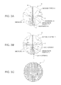
- Fig. 3A shows a dioptric power distribution of a spectacle lens
- Fig. 3B shows an astigmatism distribution of the spectacle lens
- Fig. 3C shows distortion that a wearer senses when viewing a square grid through the spectacle lens.
- Fig. 4 shows vestibulo-ocular reflex.
- Fig. 5 shows the distribution of the surface power of an outer surface of a progressive-power lens according to Example 1.
- Fig. 6 shows the distributions of the power, curvature, and radius of curvature of the outer surface versus the distance from a principal meridian (y coordinate in the horizontal direction).
- Fig. 7 shows the distribution of the power of the outer surface.
- Fig. 8 shows the distribution of the curvature of the outer surface.
- Fig. 9 shows the distribution of the radius of curvature of the outer surface.
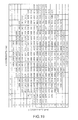
- Fig. 10 shows the magnification of the progressive-power lens according to Example 1.
- Fig. 11 shows the magnification of a progressive-power lens according to Comparative Example 1.
- Fig. 12 shows the ratio of the magnification of the progressive-power lens according to Example 1 to the magnification of the progressive-power lens according to Comparative Example 1.
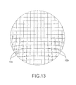
- Fig. 13 shows distortion of the square grid viewed through the progressive-power lens according to Example 1 and the progressive-power lens according to Comparative Example 1.
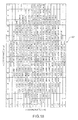
- Fig. 14 shows the magnification of a progressive-power lens according to Example 2.
- Fig. 15 shows the magnification of a progressive-power lens according to Comparative Example 2.
- Fig. 16 shows the ratio of the magnification of the progressive-power lens according to Example 2 to the magnification of the progressive-power lens according to Comparative Example 2.
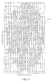
- Fig. 17 shows the magnification of a progressive-power lens according to Example 3.
- Fig. 18 shows the magnification of a progressive-power lens according to Comparative Example 3.
- Fig. 19 shows the ratio of the magnification of the progressive-power lens according to Example 3 to the magnification of the progressive-power lens according to Comparative Example 3.
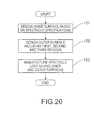
- Fig. 20 is a flowchart showing a schematic design/manufacture procedure.
- Fig. 1 is a perspective view showing an example of spectacles.
- Fig. 2A is a plan view diagrammatically showing a progressive-power lens according to an embodiment of the invention.
- Fig. 2B is a cross-sectional view diagrammatically showing the progressive-power lens.
- the right and left sides are considered as the right and left sides viewed from a user (wearer, eyeball).
- Spectacles 1 include a pair of right and left spectacle lenses 10R, 10L for the right and left eyes and a spectacle frame 20 to which the lenses 10R and 10L are attached.
- Each of the spectacle lenses 10R and 10L is a progressive multifocal lens (progressive-power lends)
- Each of the lenses 10R and 10L basically has a meniscus shape convex toward an object.
- Each of the lenses 10R and 10L therefore has an object-side surface (convex surface, hereinafter also referred to as outer surface) 19A and an eyeball-side (user-side) surface (concave surface, hereinafter also referred to as inner surface) 19B.
- object-side surface convex surface, hereinafter also referred to as outer surface
- eyeball-side (user-side) surface concave surface, hereinafter also referred to as inner surface
- Fig. 2A shows the lens 10R for the right eye.
- the lens 10R has a distance portion 11, which is an upper viewing area that allows the wearer to view a distant object (distant vision), and a near portion 12, which is a lower viewing area that allows the wearer to view a near object (near vision) and has dioptric power (power) different from that of the distance portion 11.
- the lens 10R further has an intermediate portion (portion for intermediate vision, progressive portion, progressive corridor) 13 that connects the distance portion 11 and the near portion 12 to each other in such a way that the power continuously changes across the boundary therebetween.
- the lens 10R further has a. principal line of fixation 14 that connects on-lens positions that are the centers of the viewing areas for distant vision, intermediate vision, and near vision.
- a fitting point Pe which is an on-lens reference point through which the line of sight is designed to pass when the spectacle lens 10R is fit in a rim of the frame and the periphery of the rim is so shaped that the lens is fixed therein with the wearer horizontally viewing a distant object in front of the wearer (primary position), is typically positioned in the vicinity of the lower end of the distance portion 11.
- the fitting point Pe is the origin of the coordinates of the lens, and let an x coordinate be the horizontal coordinate along a horizontal reference line X passing through the fitting point Pe, and a y coordinate be the vertical coordinate along a vertical reference line (principal meridian) Y passing through the fitting point Pe.
- the principal line of fixation 14 deviates from the principal meridian Y toward the nose after it passes through the fitting point Pe or a point in the vicinity thereof.
- the distance 15 between the principal line of fixation 14 and the principal meridian Y is referred to as an inset.
- a spectacle lens (lens) will be made primarily based on the spectacle lens 10R for the right eye.
- the spectacle lens described herein may be the lens 10L for the left eye, because the spectacle lens 10R for the right eye and the lens 10L for the left eye are basically symmetric with respect to the vertical central line of the spectacles 1 except differences in spectacle specifications between the right and left eyes.
- the spectacle lens for the right eye and the spectacle lens 10L for the left eye are collectively referred to as a spectacle lens (or lens) 10.
- the size of the field of view can be determined by an astigmatism distribution diagram and a spherical dioptric power equivalent distribution diagram.
- One of the important performance characteristics of the progressive-power lens 10 is the degree of shaking that the wearer who wears the progressive-power lens 10 senses when the wearer moves the head. It is noted that progressive-power lenses 10 having substantially the same astigmatism distribution and spherical dioptric power equivalent distribution may differ from each other in terms of shaking in some cases.
- Fig. 3A shows a dioptric power distribution (power distribution in dioptre (D)) of a typical progressive-power lens 10.
- Fig. 3B shows an astigmatism distribution (in dioptre (D)).
- Fig. 3C shows distortion that the wearer senses when viewing a square grid through the lens 10.
- predetermined dioptric power is added along the principal line of fixation 14.
- Adding dioptric power causes large astigmatism on both sides of the intermediate region (intermediate portion, progressive region) 13, resulting in a blurred image formed by the light having passed through either of the side regions.
- the dioptric power increases in the near portion 12 by a predetermined amount (addition dioptric power) and gradually decreases through the intermediate portion 13 and the distance portion 11.
- the dioptric power distance dioptric power, Sph
- the addition dioptric power is 2.00 D.
- the near portion 12 Due to the difference in dioptric power across the lens 10, the near portion 12, where the dioptric power is larger, forms a more magnified image than the distance portion 11, and an image of the square grid formed through portions on both sides of the intermediate portion 13 and the near portion 12 is slightly distorted. Further, the dioptric power (power) abruptly decreases in side regions 16 on the right and left sides of the intermediate portion 13 and the near portion 12 (side regions 16 horizontally outside the intermediate portion 13 and the near portion I2) as shown in Fig. 3A , and hence a less magnified image is formed through each of the side regions 16.
- the variation in the magnification at which an image is formed causes image shaking when the wearer moves the head rightward or leftward (in horizontal direction).
- Fig. 4 schematically shows vestibulo-ocular reflex (VOR).
- VOR vestibulo-ocular reflex
- a person who is looking at an object moves the head, the person's sight also moves. At this point, an image on the retina also moves.
- an eyeball 3 moves (pivotal movement (rotation) 7 of eye) to cancel the movement of the head (pivotal movement (rotation) of face, pivotal movement of head) 8
- the line of sight 2 is fixed (does not move), whereby the image on the retina does not move.
- Such reflex eyeball movement that fixes an image on the retina is called compensatory eye movement.
- Vestibulo-ocular reflex is one type of the compensatory eye movement, and pivotal movement of the head triggers the reflex action.
- a neural mechanism of the vestibulo-ocular reflex triggered by horizontal rotation (horizontal pivotal movement) of the head has been explained to some extent as follows: It is believed that the pivotal movement 8 of the head is sensed by the horizontal semicircular canal, which inhibits or excites the external ocular muscle, which then moves the eyeball 3.
- the vestibulo-ocular reflex causes the line of sight 2 passing through the spectacle lens 10 to move relative to the spectacle lens 10.
- the image on the retina therefore shakes in some cases when imaging performance of the spectacle lens 10 varies within the range over which the vestibulo-ocular reflex causes the eyeball 3 to move, that is, the range over which the line of sight 2 moves due to the vestibulo-ocular reflex.
- Ms represents a shape factor
- Mp represents a power factor
- the base curve D and the inner vertex power P are measured in dioptre (D), and the thickness t and the distance L are measured in meter (m) .
- Expression (5) shows that the magnification M decreases as the power P decreases, which means that the magnification M at which an image is formed through either of the side regions 16 is smaller than the magnification at which an image is formed through the intermediate portion 13 and the magnification at which an image is formed through the near portion 12.
- the magnification M can be increased by increasing the base curve D, that is, the surface power of the outer surface 19A.
- an inner-surface progressive lens is employed, and the change in magnification at which an image is formed through either of the side regions 16 and hence the amount of image shaking is reduced by increasing the surface power of the portions of the outer surface 19A that face the side regions 16 located outside the intermediate portion 13 and the near portion 12 of the inner surface 19B.
- a progressive-power lens 10a according to Example 1 was designed based on an inner-surface progressi ve-power lens "Seiko Super P-1" type A (refractive index: 1.67) manufactured by Seiko Epson Corp. to which the following spectacle specifications are applied: the length of the progressive corridor is 14 mm; the prescribed dioptric power (distance dioptric power, Sph) is 0.00 D; and the addition dioptric power (Add) is 1.00 (D). Further, the diameter of the lens 10a is 65 mm, and no astigmatism dioptric power is considered.
- the progressive-power lens 10a therefore has a progressive inner surface 19B including the distance portion 11, the near portion 12, the intermediate portion 13, and the side regions 16 shown in. Fig. 3A .
- Fig. 5 shows the distribution of the surface power of the outer surface 19A of the progressive-power lens 10a according to Example 1.
- Fig. 6 shows the distributions of the power, curvature, and radius of curvature of the outer surface 19A versus the distance from the principal meridian Y (y coordinate in the horizontal direction).
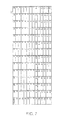
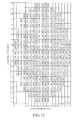
- Fig. 7 shows the distribution of the power of the outer surface 19A in the form of coordinate matrix (x,y).
- Fig. 8 shows the distribution of the curvature of the outer surface 9A in the form of coordinate matrix (x,y).
- Fig. 9 shows the distribution of the radius of curvature of the outer surface 19A in the form of coordinate matrix (x,y).
- the outer surface 9A is basically a spherical surface having a surface power of 4.00 (D) and has aspherical regions on both sides thereof. In the aspherical regions, the surface power monotonously increases gradually toward the periphery. That is, the object-side surface (outer surface) 19A has a first region 31 extending along the principal meridian Y and having a spherical shape having first curvature r1 (first surface power D1), a second region 32 facing (corresponding to) the distance portion 11 and having a spherical shape having second curvature r2 (second surface power D2), which is equal to the first curvature r1, and a third region 33 located outside the first region 31 and below the second region 32 and having third curvature r3 (third surface power D3), which is greater than the first curvature r1.
- the third region 33 is, in practice, the region of the outer surface 9A that is outside the intermediate portion 13 and the near portion 12 of the inner surface 19B in the horizontal
- the first curvature r1 and the second curvature r2 are 6.042 (1/m), and the first surface power D1 and the second surface power D2 are 4.0 (D).
- the third curvature r3, which is greater than the first curvature r1, gradually increases from the value of 6. 042 (1/m) at the boundary between the first region 31 and the third region 33 with distance from the boundary outward in the horizontal direction and reaches 8.308 (1/m) in the vicinity of the periphery (edge).
- the third surface power D3 is greater than the first surface power D1, gradually increases from the value of 4.0 (D) at the boundary between the first region 31 and the third region 33 with distance from the boundary outward in the horizontal direction, and reaches 5.5 (D) in the vicinity of the periphery (edge).
- the first region 31 and the second region 32 are formed of a spherical surface
- the third region 33 is formed of an aspherical surface.
- the third curvature r3 of the third region 33 monotonously increases with distance from the principal meridian Y outward in the horizontal direction.
- the isoquant curves representing the third surface power D3 corresponding to the third curvature r3 of the third region 33 are spaced substantially uniformly.
- the width W of the first region 31 measured on both sides of the principal meridian Y is 8 mm (distance from principal meridian Y (y coordinate) is ⁇ 4 mm), which satisfies the condition (1) described above.
- the inset of the near portion 12, that is, the distance 15 between the principal line of fixation 14 in the near portion 12 and the principal meridian Y ranges from 2 to 3 mm.
- the intermediate portion (progressive portion) 13 is accommodated in the fixed-curvature region, whereby the viewing area of the intermediate portion 13, which has the narrowest viewing area, can be ensured.
- the near portion 12 of a current progressive-power lens 10 is inset by 5 mm at the maximum, which is practically the greatest value necessary for an object distance of 15 cm.
- another fixed viewing area of 2 mm may be ensured by increasing the width W of the first region 31 measured on both sides of the principal meridian Y to 14 mm, that is, by providing a fixed-curvature region having a width of ⁇ 7 mm with respect to the principal meridian Y.
- the inner surface (concave surface) 19B may be configured based on basic progressive design.
- the width W of the first region 31 is close to the lower limit of the condition (1), that is, when the outer surface (convex surface) 19A has a fixed-curvature region having a width of ⁇ 3 mm measured on both sides of the principal meridian Y, the first region 31 alone may not ensure the width of a clear field of the near portion 12 in some cases.
- the viewing area of the near portion 12 can be ensured by correcting the progressive design of the inner surface (concave surface) 19B.
- the inner surface (concave surface) 19B For example, it is conceivable to add an aspherical element whose curvature is distributed in the horizontal direction in accordance with the change in curvature of the outer surface 19A to the inner surface 19B.
- a progressive-power lens 10b was designed as Comparative Example 1 and compared with the progressive-power lens 10a according to Example 1.
- the progressive-power lens 10b has a spherical outer surface 19A having a surface power of 4.0 (D) and the same inner surface 19B as that of the progressive-power lens 10a.
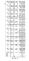
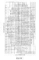
- Fig. 10 shows the magnification at which an image is formed through the progressive-power lens 10a according to Example 1 in the form of coordinate matrix (x,y).
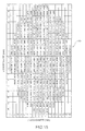
- Fig. 11 shows the magnification at which an image is formed through the progressive-power lens 10b according to Comparative Example 1 in the form of coordinate matrix (x,y).
- Fig. 12 shows the ratio of the magnification of the progressive-power lens 10a according to Example 1 to the magnification of the progressive-power lens 10b according to Comparative Example 1 in the form of coordinate matrix (x,y).
- magnification For example, look at the magnification at a y coordinate of -24 mm, which is close to the boundary between the intermediate portion 13 and the near portion 12, in the progressive-power lens 10b according to Comparative Example 1 shown in Fig. 11 .
- the magnification is 1.0303957 at an x coordinate of 0 mm, which is on the principal meridian Y, and 1.0237506 at an x coordinate of -28 mm, which is apart sideways. Therefore, an image formed through an outer region is smaller than an image formed through a region along the principal meridian Y, and the ratio of the magnification at which an image is formed through the outer region to the magnification at which an image is formed through the region along the principal meridian Y is about 99.36%.
- magnification is 1.0304005 at an x coordinate of 0 mm and 1.0246259 at an x coordinate of -28 mm, which is apart sideways. Therefore, an image formed through the outer third region 33 is still smaller than an image formed through the first region 31 along the principal meridian Y, but the magnification in the outer third region 33 is greater than the corresponding value in Comparative Example 1 and the magnification ratio is about 99.44%.
- the ratio of the magnification at which an image is formed through either of (right and left) outer regions in the horizontal direction to the magnification at which an image is formed through a region in the vicinity of the principal meridian Y is improved by about 0.08, whereby the degree of image shaking produced when the line of sight 2 is moved in the horizontal direction from or to the near portion 12 or the intermediate portion 13 can be reduced.
- the magnification is greater substantially across the side regions 16 outside the intermediate portion 13 and the near portion 12 than that in the progressive-power lens 10b according to Comparative Example 1, whereby the difference in magnification between an image formed through a region in the vicinity of the principal meridian Y and an image formed through a region apart in the horizontal direction from the principal meridian Y is reduced, as shown Fig. 12 .
- Fig. 13 shows distortion of the square grid viewed through the progressive-power lens 10a according to Example 1 and the progressive-power lens 10b according to Comparative Example 1.
- the progressive-power lens 10b according to Comparative Example 1 since the magnification decreases on both sides of the intermediate portion 13 and the near portion 12, the resultant image becomes smaller.
- the change in size of the resultant image is small.
- the spectacles 1 using the progressive-power lens 10a allow a user who frequently looks an object through the intermediate portion 13 and the near portion 12, particularly a user who frequently looks an object through the near portion 12, for example, a user whose job is assembling precise parts, to look at an object with less image shaking resulting from horizontal movement of the line of sight 2 and hence provide excellent viewing performance.
- a progressive-power lens 10c according to Example 2 was designed based on the inner-surface progressive-power lens "Seiko Super P-1" type A (refractive index: 1.67) manufactured by Seiko Epson Corp. to which the following spectacle specifications are applied: the length of the progressive corridor is 14 mm; the prescribed dioptric power (distance dioptric power, Sph) is 0.00 D; and the addition dioptric power (Add) is 2.00 (D).
- the other conditions are the same as those of the progressive-power lens 10a according to Example 1, and the progressive inner surface 19B includes the distance portion 11, the near portion 12, the intermediate portion 13, and the side regions 16.
- the outer surface 19A is basically a spherical surface having a surface power of 4.00 (D) and has aspherical regions on both sides thereof. In the aspherical regions, the surface power monotonously increases gradually toward the periphery. Specifically, the outer surface 19A is the same as that of the progressive-power lens 10a according to Example 1.
- the object-side surface (outer surface) 19A has a first region 31 extending along the principal meridian Y and having a spherical shape having first curvature r1 (first surface power D1), a second region 32 facing the distance portion 11 and having a spherical shape having second curvature r2 (second surface power D2), which is equal to the first curvature r1, and a third region 33 located outside the first region 31 and below the second region 32 and having third curvature r3 (third surface power D3), which is greater than the first curvature r1.
- a progressive-power lens 10d was designed as Comparative Example 2 and compared with the progressive-power lens 10c according to Example 2.
- the progressive-power lens 10d has a spherical outer surface 19A having a surface power of 4.0 (D) and the same inner surface 19B as that of the progressive-power lens 10c.
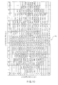
- Fig. 14 shows the magnification at which an image is formed through the progressive-power lens 10c according to Example 2 in the form of coordinate matrix (x, y) .
- Fig. 15 shows the magnification at which an image is formed through the progressive-power lens 10d according to Comparative Example 2 in the form of coordinate matrix (x,y).
- Fig. 16 shows the ratio of the magnification of the progressive-power lens 10c according to Example 2 to the magnification of the progressive-power lens 10d according to Comparative Example 2 in the form of coordinate matrix (x,y).
- Example 1 look at the magnification at a y coordinate of -24 mm, which is close to the boundary between the intermediate portion 13 and the near portion 12, in the progressive-power lens 10d according to Comparative Example 2 shown in Fig. 15 .
- the magnification is 1.0633531 at an x coordinate of 0 mm, which is on the principal meridian Y, and 1.0048368 at an x coordinate of -28 mm, which is apart sideways.
- an image formed through an outer region is smaller than an image formed through a region along the principal meridian Y, and the ratio of the magnification at which an image is formed through the outer region to the magnification at which an image is formed through the region along the principal meridian Y is about 94.49%.
- magnification is 1.0633580 at an x coordinate of 0 mm and 1.0056959 at an x coordinate of -28 mm, which is apart sideways. Therefore, an image formed through the outer third region 33 is still smaller than an image formed through the first region 31 along the principal meridian Y, but the magnification in the outer third region 33 is greater than the corresponding value in Comparative Example 2 and the magnification ratio is about 94.58%.
- the ratio of the magnification at which an image is formed through either of the (right and left) outer regions in the horizontal direction to the magnification at which an image is formed through a region in the vicinity of the principal meridian Y is improved by about 0.09, whereby the degree of image shaking produced when the line of sight 2 is moved in the horizontal direction from or to the near portion 12 or the intermediate portion 13 can be reduced.
- the magnification is greater substantially across the side regions 16 outside the intermediate portion 13 and the near portion 12 than that in the progressive-power lens 10d according to Comparative Example 2, whereby the difference in magnification between an image formed through a region in the vicinity of the principal meridian Y and an image formed through a region apart in the horizontal direction from the principal meridian Y is reduced, as shown in Fig. 16 .
- a progressive-power lens 10e according to Example 3 was designed based on the inner-surface progressive-power lens "Seiko Super P-1" type A (refractive index: 1.67) manufactured by Seiko Epson Corp. to which the following spectacle specifications are applied: the length of the progressive corridor is 14 mm; the prescribed dioptric power (distance dioptric power, Sph) is 0.00 D; and the addition dioptric power (Add) is 3.00 (D).
- the other conditions are the same as those of the progressive-power lens 10a according to Example 1, and the progressive inner surface 19B includes the distance portion 11, the near portion 12, the intermediate portion 13, and the side regions 16.
- the outer surface 19A is basically a spherical surface having a surface power of 4.00 (D) and has aspherical regions on both sides thereof. In the aspherical regions, the surface power monotonously increases gradually toward the periphery. Specifically, the outer surface 19A is the same as that of the progressive-power lens 10a according to Example 1.
- the object-side surface (outer surface) 19A has a first region 31 extending along the principal meridian Y and having a spherical shape having first curvature r1 (first surface power D1), a second region 32 facing the distance portion 11 and having a spherical shape having second curvature r2 (second surface power D2), which is equal to the first curvature r1, and a third region 33 located outside the first region 31 and below the second region 32 and having third curvature r3 (third surface power D3), which is greater than the first curvature r1.
- a progressive-power lens 10f was designed as Comparative Example 3 and compared with the progressive-power lens 10e according to Example 3.
- the progressive-power lens 10f has a spherical outer surface 19A having a surface power of 4.0 (D) and the same inner surface 19B as that of the progressive-power lens 10e.
- Fig. 17 shows the magnification at which an image is formed through the progressive-power lens 10e according to Example 3 in the form of coordinate matrix (x,y).
- Fig. 18 shows the magnification at which an image is formed through the progressive-power lens 10f according to Comparative Example 3 in the form of coordinate matrix (x,y).
- Fig. 19 shows the ratio of the magnification of the progressive-power lens 10e according to Example 3 to the magnification of the progressive-power lens 10f according to Comparative Example 3 in the form of coordinate matrix (x,y).
- Example 1 look at the magnification at a y coordinate of -24 mm, which is close to the boundary between. the intermediate portion 13 and the near portion 12, in the progressive-power lens 10f according to Comparative Example 3 shown in Fig. 18 .
- the magnification is 1.0987136 at an x coordinate of 0 mm, which is on the principal meridian Y, and 1. 0048368 at an x coordinate of -28 mm, which is apart sideways.
- an image formed through an outer region is smaller than an image formed through a region along the principal meridian Y, and the ratio of the magnification at which an image is formed through the outer region to the magnification at which an image is formed through the region along the principal meridian Y is about 91.46%.
- magnification at a y coordinate of -24 mm in the progressive-power lens lose according to Example 3 shown in Fig. 17 The magnification is 1.0987186 at an x coordinate of 0 mm and 1.0056959 at an x coordinate of -28 mm, which is apart sideways. Therefore, an image formed through the outer third region 33 is still smaller than an image formed through the first region 31 along the principal meridian Y, but the magnification in the outer third region 33 is greater than the corresponding value in Comparative Example 3 and the magnification ratio is about 91.53%.
- the ratio of the magnification at which an image is formed through either of the (right and left) outer regions in the horizontal direction to the magnification at which an image is formed through a region in the vicinity of the principal meridian Y is improved by about 0.07, whereby the degree of image shaking produced when the line of sight 2 is moved in the horizontal direction from or to the near portion 12 or the intermediate portion 13 can be reduced.
- the magnification is greater substantially across the side regions 16 outside the intermediate portion 13 and the near portion 12 than that of the progressive-power lens 10f according to Comparative Example 3, whereby the difference in magnification between an image formed through a region in the vicinity of the principal meridian Y and an image formed through a region apart in the horizontal direction from the principal meridian Y is reduced, as shown in Fig. 19 .
- the inner surface 19B is designed based on the addition dioptric power in the spectacle specifications being 1.00 (D), 2.00 (D), and 3.00 (D), respectively.
- the progressive-power lenses 10a, 10c, and 10e have the common outer surface 19A, which has the spherical first region 31 extending along the principal meridian Y, the spherical second region 32 facing the distance portion 11, and the aspherical third region 33 facing the side regions 16 and having surface power increasing with distance outward from the principal meridian Y.
- the difference in magnification in the horizontal direction may be further reduced by appropriately setting the addition dioptric power in the spectacle specifications to select the change from the first curvature r1 and the second curvature r2 of the first region 31 and the second region 32 of the outer surface 19A to the third curvature r3 of the third region 33 of the outer surface 19A.
- Fig. 20 shows a procedure of designing and manufacturing the progressive power-lens 10.
- the inner surface (eyeball-side surface) 19B is designed based on spectacle specifications.
- the inner surface 19B is a progressive surface and includes the distance portion 11, the intermediate portion 13, and the near portion 12.
- the outer surface (object-side surface) 19A including the first region 31, the second region 32, and the third region 33 is designed.
- the outer surface 19A may be a common surface irrespective of the spectacle specifications, that is, may have a common first region 31, a common second region 32, and a common region 33 irrespective of the spectacle specifications.
- the outer surface 19A may be designed in accordance with a progressive inner surface having an addition dioptric power of 0.5 (D), and then a progressive-power lens having an addition dioptric power of 3.5 (D) may be designed based on the thus designed outer surface (convex surface) 19A.
- a pre-manufactured, semi-finished lens can be prepared in advance irrespective of the addition dioptric power, which is preferable to reduce the manufacturing cost.
- the outer surface 19A may be designed to have a first region having common first curvature, a second region having common second curvature, and a third region having common third curvature.
- three types of outer surface 19A having addition dioptric power of 0.50, 1.00, and 2.50 may be designed in advance, and a progressive-power lens 10 whose addition dioptric power falls within any of the specific ranges may be manufactured by using the corresponding one of the common outer surfaces 19A. In this way, more satisfactory design can be made for predetermined addition dioptric power while the manufacturing cost is kept low.
- a spectacle progressive-power lens 10 having the thus designed inner and outer surfaces is manufactured.
- the above description has been made with reference to a progressive-power lens having an outer surface 19A formed of a common curved surface irrespective of spectacle specifications, particularly addition dioptric power specification.
- the outer surface 19A may be formed of a curved surface having any other shape based on spectacle specifications within those set forth in the appended claims.
- the above description has been made of the case where the third region 33 is formed of an aspherical surface over which the curvature (surface power) changes.
- the third region 33 may alternatively be formed of a spherical surface having fixed curvature (surface power).
Landscapes
- Health & Medical Sciences (AREA)
- Ophthalmology & Optometry (AREA)
- Physics & Mathematics (AREA)
- General Health & Medical Sciences (AREA)
- General Physics & Mathematics (AREA)
- Optics & Photonics (AREA)
- Eyeglasses (AREA)
Applications Claiming Priority (1)
| Application Number | Priority Date | Filing Date | Title |
|---|---|---|---|
| JP2011037962A JP5897260B2 (ja) | 2011-02-24 | 2011-02-24 | 累進屈折力レンズおよびその設計方法 |
Publications (3)
| Publication Number | Publication Date |
|---|---|
| EP2492740A2 true EP2492740A2 (fr) | 2012-08-29 |
| EP2492740A3 EP2492740A3 (fr) | 2013-03-27 |
| EP2492740B1 EP2492740B1 (fr) | 2016-02-10 |
Family
ID=45656395
Family Applications (1)
| Application Number | Title | Priority Date | Filing Date |
|---|---|---|---|
| EP12156484.3A Active EP2492740B1 (fr) | 2011-02-24 | 2012-02-22 | Lentille progressive et procédé pour la fabrication de la lentille progressive |
Country Status (4)
| Country | Link |
|---|---|
| US (1) | US8777407B2 (fr) |
| EP (1) | EP2492740B1 (fr) |
| JP (1) | JP5897260B2 (fr) |
| CN (1) | CN102650748B (fr) |
Cited By (3)
| Publication number | Priority date | Publication date | Assignee | Title |
|---|---|---|---|---|
| WO2014037482A3 (fr) * | 2012-09-07 | 2014-06-26 | Essilor International (Compagnie Generale D'optique) | Procédé de détermination de lentille ophtalmique progressive |
| WO2015150269A1 (fr) * | 2014-04-01 | 2015-10-08 | Essilor International (Compagnie Generale D'optique) | Verre de lunettes ophtalmique multifocal agencé pour transmettre une image supplémentaire |
| EP3671323A1 (fr) * | 2018-12-20 | 2020-06-24 | Essilor International (Compagnie Generale D'optique) | Procédé de génération de données de surface virtuelle d'une lentille d'addition progressive |
Families Citing this family (4)
| Publication number | Priority date | Publication date | Assignee | Title |
|---|---|---|---|---|
| EP2937728B1 (fr) * | 2012-12-19 | 2023-03-08 | HOYA Corporation | Appareil et procédé de fabrication pour verres de lunettes |
| US10330952B2 (en) | 2012-12-19 | 2019-06-25 | Hoya Corporation | Spectacle lenses |
| PE20190549A1 (es) * | 2016-07-08 | 2019-04-16 | Vision Ease Lp | Revestimiento directo de preforma de lente optimizado |
| TWI719425B (zh) * | 2019-03-15 | 2021-02-21 | 中華寶島眼鏡有限公司 | 一種無盲區三葉視控鏡片 |
Citations (1)
| Publication number | Priority date | Publication date | Assignee | Title |
|---|---|---|---|---|
| WO1997019382A1 (fr) | 1995-11-24 | 1997-05-29 | Seiko Epson Corporation | Verres a focale multiple et a indice de gradient, verres de lunettes, et fabrication de verres a focale multiple et a indice de gradient |
Family Cites Families (14)
| Publication number | Priority date | Publication date | Assignee | Title |
|---|---|---|---|---|
| US5123725A (en) * | 1986-12-19 | 1992-06-23 | American Optical Corporation | Progressive addition spectacle lens |
| US5048945A (en) * | 1989-07-14 | 1991-09-17 | Nikon Corporation | Progressive power lens |
| JP2503664B2 (ja) * | 1989-07-14 | 1996-06-05 | 株式会社ニコン | 累進焦点レンズ |
| JP3273783B2 (ja) * | 1989-07-17 | 2002-04-15 | オプティッシェ.ウエルケ.ゲー.ローデンストック | 正の遠隔視覚パワーを有する眼鏡用プログレッシブレンズ |
| JP3800629B2 (ja) | 1995-11-24 | 2006-07-26 | セイコーエプソン株式会社 | 眼鏡用多焦点レンズおよび眼鏡レンズ |
| FR2783938B1 (fr) * | 1998-09-28 | 2000-11-17 | Essilor Int | Lentilles ophtalmiques toriques |
| US6231184B1 (en) * | 1999-11-12 | 2001-05-15 | Johnson & Johnson Vision Care, Inc. | Progressive addition lenses |
| JP4475654B2 (ja) * | 2005-05-19 | 2010-06-09 | 東海光学株式会社 | 累進屈折力レンズおよびその製造方法 |
| US7959285B2 (en) | 2006-07-20 | 2011-06-14 | Nikon-Essilor Co., Ltd. | Method for designing progressive refraction lens, method for manufacturing the same, and eyeglasses lens supplying system |
| FR2908191B1 (fr) | 2006-11-07 | 2008-12-26 | Essilor Int | Lentille ophtalmique |
| EP2130090A4 (fr) * | 2007-03-07 | 2011-11-02 | Pixeloptics Inc | Lentille multifocale possédant une région de puissance optique progressive et une discontinuité |
| JP2009139786A (ja) * | 2007-12-10 | 2009-06-25 | Seiko Epson Corp | 眼鏡レンズ及びその製造方法 |
| DE102009053467B4 (de) * | 2008-11-14 | 2018-01-18 | Rodenstock Gmbh | Ophthalmische Linse mit peripherer Brechkraftvariation |
| JP5286473B2 (ja) * | 2009-03-31 | 2013-09-11 | ホーヤ レンズ マニュファクチャリング フィリピン インク | 累進屈折力眼鏡レンズの設計方法 |
-
2011
- 2011-02-24 JP JP2011037962A patent/JP5897260B2/ja active Active
-
2012
- 2012-02-22 EP EP12156484.3A patent/EP2492740B1/fr active Active
- 2012-02-23 US US13/403,895 patent/US8777407B2/en active Active
- 2012-02-23 CN CN201210043828.6A patent/CN102650748B/zh active Active
Patent Citations (1)
| Publication number | Priority date | Publication date | Assignee | Title |
|---|---|---|---|---|
| WO1997019382A1 (fr) | 1995-11-24 | 1997-05-29 | Seiko Epson Corporation | Verres a focale multiple et a indice de gradient, verres de lunettes, et fabrication de verres a focale multiple et a indice de gradient |
Cited By (6)
| Publication number | Priority date | Publication date | Assignee | Title |
|---|---|---|---|---|
| WO2014037482A3 (fr) * | 2012-09-07 | 2014-06-26 | Essilor International (Compagnie Generale D'optique) | Procédé de détermination de lentille ophtalmique progressive |
| US9557578B2 (en) | 2012-09-07 | 2017-01-31 | Essilor International (Compagnie Generale D'optique) | Methods for determining a progressive ophthalmic lens |
| WO2015150269A1 (fr) * | 2014-04-01 | 2015-10-08 | Essilor International (Compagnie Generale D'optique) | Verre de lunettes ophtalmique multifocal agencé pour transmettre une image supplémentaire |
| US10126568B2 (en) | 2014-04-01 | 2018-11-13 | Essilor International | Multifocal ophthalmic spectacle lens arranged to output a supplementary image |
| EP3671323A1 (fr) * | 2018-12-20 | 2020-06-24 | Essilor International (Compagnie Generale D'optique) | Procédé de génération de données de surface virtuelle d'une lentille d'addition progressive |
| WO2020126621A1 (fr) * | 2018-12-20 | 2020-06-25 | Essilor International | Procédé de génération de données de surface virtuelle d'une lentille d'addition progressive |
Also Published As
| Publication number | Publication date |
|---|---|
| EP2492740A3 (fr) | 2013-03-27 |
| CN102650748B (zh) | 2016-12-14 |
| US8777407B2 (en) | 2014-07-15 |
| US20120218510A1 (en) | 2012-08-30 |
| EP2492740B1 (fr) | 2016-02-10 |
| CN102650748A (zh) | 2012-08-29 |
| JP5897260B2 (ja) | 2016-03-30 |
| JP2012173674A (ja) | 2012-09-10 |
Similar Documents
| Publication | Publication Date | Title |
|---|---|---|
| EP2492740B1 (fr) | Lentille progressive et procédé pour la fabrication de la lentille progressive | |
| US9581831B2 (en) | Optical lens, method for designing optical lens, and apparatus for manufacturing optical lens | |
| US8807746B2 (en) | Spectacle lens, spectacles, and method for manufacturing spectacle lens | |
| JPH0690368B2 (ja) | 累進多焦点レンズ及び眼鏡 | |
| EP2678732B1 (fr) | Verres de lunettes | |
| CN101114061A (zh) | 眼镜片的设计方法、眼镜片和眼镜 | |
| JP2010250347A (ja) | 2つの非球面、特にプログレッシブ表面を有するプログレッシブメガネレンズ及びそのメガネレンズを算出する方法 | |
| JP5976366B2 (ja) | 累進屈折力レンズおよび累進屈折力レンズの設計方法 | |
| JP5822483B2 (ja) | 眼鏡用レンズ | |
| EP2498119B1 (fr) | Lentille progressive et procédé de conception de lentille progressive | |
| US8684523B2 (en) | Spectacle lens, spectacle lens design method, and design apparatus | |
| JP2012220655A (ja) | 累進屈折力レンズの設計方法 | |
| JP2016026324A (ja) | 眼鏡用レンズ、眼鏡、眼鏡レンズの設計方法、及び設計装置 | |
| JPH07294859A (ja) | 累進多焦点レンズ | |
| JP6095271B2 (ja) | レンズセット、レンズ設計方法及びレンズ製造方法 | |
| US8092012B2 (en) | Single vision spectacle lens | |
| KR100705120B1 (ko) | 누진 굴절력 렌즈 및 제조 방법 | |
| JP5749497B2 (ja) | 両面累進レンズ、その製造方法、およびその製造装置 | |
| JPH08211340A (ja) | 累進多焦点レンズ及び眼鏡 | |
| JP2013182249A (ja) | レンズセット、レンズ設計方法及びレンズ製造方法 | |
| JP2013182250A (ja) | レンズセット、レンズ設計方法及びレンズ製造方法 |
Legal Events
| Date | Code | Title | Description |
|---|---|---|---|
| PUAI | Public reference made under article 153(3) epc to a published international application that has entered the european phase |
Free format text: ORIGINAL CODE: 0009012 |
|
| AK | Designated contracting states |
Kind code of ref document: A2 Designated state(s): AL AT BE BG CH CY CZ DE DK EE ES FI FR GB GR HR HU IE IS IT LI LT LU LV MC MK MT NL NO PL PT RO RS SE SI SK SM TR |
|
| AX | Request for extension of the european patent |
Extension state: BA ME |
|
| PUAL | Search report despatched |
Free format text: ORIGINAL CODE: 0009013 |
|
| AK | Designated contracting states |
Kind code of ref document: A3 Designated state(s): AL AT BE BG CH CY CZ DE DK EE ES FI FR GB GR HR HU IE IS IT LI LT LU LV MC MK MT NL NO PL PT RO RS SE SI SK SM TR |
|
| AX | Request for extension of the european patent |
Extension state: BA ME |
|
| RIC1 | Information provided on ipc code assigned before grant |
Ipc: G02C 7/06 20060101ALI20130219BHEP Ipc: G02C 7/02 20060101AFI20130219BHEP |
|
| RAP1 | Party data changed (applicant data changed or rights of an application transferred) |
Owner name: HOYA LENS MANUFACTURING PHILIPPINES INC. |
|
| 17P | Request for examination filed |
Effective date: 20130917 |
|
| RBV | Designated contracting states (corrected) |
Designated state(s): AL AT BE BG CH CY CZ DE DK EE ES FI FR GB GR HR HU IE IS IT LI LT LU LV MC MK MT NL NO PL PT RO RS SE SI SK SM TR |
|
| RAP1 | Party data changed (applicant data changed or rights of an application transferred) |
Owner name: EHS LENS PHILIPPINES, INC. |
|
| RAP1 | Party data changed (applicant data changed or rights of an application transferred) |
Owner name: EHS LENS PHILIPPINES, INC. |
|
| GRAP | Despatch of communication of intention to grant a patent |
Free format text: ORIGINAL CODE: EPIDOSNIGR1 |
|
| RIC1 | Information provided on ipc code assigned before grant |
Ipc: G02C 7/06 20060101ALI20150806BHEP Ipc: G02C 7/02 20060101AFI20150806BHEP |
|
| INTG | Intention to grant announced |
Effective date: 20150827 |
|
| RIN1 | Information on inventor provided before grant (corrected) |
Inventor name: SUZUKI, YOHEI Inventor name: KATO, KAZUTOSHI |
|
| GRAS | Grant fee paid |
Free format text: ORIGINAL CODE: EPIDOSNIGR3 |
|
| GRAA | (expected) grant |
Free format text: ORIGINAL CODE: 0009210 |
|
| AK | Designated contracting states |
Kind code of ref document: B1 Designated state(s): AL AT BE BG CH CY CZ DE DK EE ES FI FR GB GR HR HU IE IS IT LI LT LU LV MC MK MT NL NO PL PT RO RS SE SI SK SM TR |
|
| REG | Reference to a national code |
Ref country code: GB Ref legal event code: FG4D |
|
| REG | Reference to a national code |
Ref country code: AT Ref legal event code: REF Ref document number: 774936 Country of ref document: AT Kind code of ref document: T Effective date: 20160215 Ref country code: CH Ref legal event code: EP |
|
| REG | Reference to a national code |
Ref country code: FR Ref legal event code: PLFP Year of fee payment: 5 |
|
| REG | Reference to a national code |
Ref country code: IE Ref legal event code: FG4D |
|
| REG | Reference to a national code |
Ref country code: DE Ref legal event code: R096 Ref document number: 602012014610 Country of ref document: DE |
|
| REG | Reference to a national code |
Ref country code: LT Ref legal event code: MG4D |
|
| REG | Reference to a national code |
Ref country code: NL Ref legal event code: MP Effective date: 20160210 |
|
| REG | Reference to a national code |
Ref country code: AT Ref legal event code: MK05 Ref document number: 774936 Country of ref document: AT Kind code of ref document: T Effective date: 20160210 |
|
| PG25 | Lapsed in a contracting state [announced via postgrant information from national office to epo] |
Ref country code: FI Free format text: LAPSE BECAUSE OF FAILURE TO SUBMIT A TRANSLATION OF THE DESCRIPTION OR TO PAY THE FEE WITHIN THE PRESCRIBED TIME-LIMIT Effective date: 20160210 Ref country code: GR Free format text: LAPSE BECAUSE OF FAILURE TO SUBMIT A TRANSLATION OF THE DESCRIPTION OR TO PAY THE FEE WITHIN THE PRESCRIBED TIME-LIMIT Effective date: 20160511 Ref country code: HR Free format text: LAPSE BECAUSE OF FAILURE TO SUBMIT A TRANSLATION OF THE DESCRIPTION OR TO PAY THE FEE WITHIN THE PRESCRIBED TIME-LIMIT Effective date: 20160210 Ref country code: ES Free format text: LAPSE BECAUSE OF FAILURE TO SUBMIT A TRANSLATION OF THE DESCRIPTION OR TO PAY THE FEE WITHIN THE PRESCRIBED TIME-LIMIT Effective date: 20160210 Ref country code: NO Free format text: LAPSE BECAUSE OF FAILURE TO SUBMIT A TRANSLATION OF THE DESCRIPTION OR TO PAY THE FEE WITHIN THE PRESCRIBED TIME-LIMIT Effective date: 20160510 Ref country code: IT Free format text: LAPSE BECAUSE OF FAILURE TO SUBMIT A TRANSLATION OF THE DESCRIPTION OR TO PAY THE FEE WITHIN THE PRESCRIBED TIME-LIMIT Effective date: 20160210 |
|
| PG25 | Lapsed in a contracting state [announced via postgrant information from national office to epo] |
Ref country code: NL Free format text: LAPSE BECAUSE OF FAILURE TO SUBMIT A TRANSLATION OF THE DESCRIPTION OR TO PAY THE FEE WITHIN THE PRESCRIBED TIME-LIMIT Effective date: 20160210 Ref country code: BE Free format text: LAPSE BECAUSE OF NON-PAYMENT OF DUE FEES Effective date: 20160229 Ref country code: PT Free format text: LAPSE BECAUSE OF FAILURE TO SUBMIT A TRANSLATION OF THE DESCRIPTION OR TO PAY THE FEE WITHIN THE PRESCRIBED TIME-LIMIT Effective date: 20160613 Ref country code: LT Free format text: LAPSE BECAUSE OF FAILURE TO SUBMIT A TRANSLATION OF THE DESCRIPTION OR TO PAY THE FEE WITHIN THE PRESCRIBED TIME-LIMIT Effective date: 20160210 Ref country code: RS Free format text: LAPSE BECAUSE OF FAILURE TO SUBMIT A TRANSLATION OF THE DESCRIPTION OR TO PAY THE FEE WITHIN THE PRESCRIBED TIME-LIMIT Effective date: 20160210 Ref country code: AT Free format text: LAPSE BECAUSE OF FAILURE TO SUBMIT A TRANSLATION OF THE DESCRIPTION OR TO PAY THE FEE WITHIN THE PRESCRIBED TIME-LIMIT Effective date: 20160210 Ref country code: IS Free format text: LAPSE BECAUSE OF FAILURE TO SUBMIT A TRANSLATION OF THE DESCRIPTION OR TO PAY THE FEE WITHIN THE PRESCRIBED TIME-LIMIT Effective date: 20160610 Ref country code: PL Free format text: LAPSE BECAUSE OF FAILURE TO SUBMIT A TRANSLATION OF THE DESCRIPTION OR TO PAY THE FEE WITHIN THE PRESCRIBED TIME-LIMIT Effective date: 20160210 Ref country code: LV Free format text: LAPSE BECAUSE OF FAILURE TO SUBMIT A TRANSLATION OF THE DESCRIPTION OR TO PAY THE FEE WITHIN THE PRESCRIBED TIME-LIMIT Effective date: 20160210 Ref country code: SE Free format text: LAPSE BECAUSE OF FAILURE TO SUBMIT A TRANSLATION OF THE DESCRIPTION OR TO PAY THE FEE WITHIN THE PRESCRIBED TIME-LIMIT Effective date: 20160210 |
|
| REG | Reference to a national code |
Ref country code: CH Ref legal event code: PL |
|
| PG25 | Lapsed in a contracting state [announced via postgrant information from national office to epo] |
Ref country code: CH Free format text: LAPSE BECAUSE OF NON-PAYMENT OF DUE FEES Effective date: 20160229 Ref country code: EE Free format text: LAPSE BECAUSE OF FAILURE TO SUBMIT A TRANSLATION OF THE DESCRIPTION OR TO PAY THE FEE WITHIN THE PRESCRIBED TIME-LIMIT Effective date: 20160210 Ref country code: LI Free format text: LAPSE BECAUSE OF NON-PAYMENT OF DUE FEES Effective date: 20160229 Ref country code: DK Free format text: LAPSE BECAUSE OF FAILURE TO SUBMIT A TRANSLATION OF THE DESCRIPTION OR TO PAY THE FEE WITHIN THE PRESCRIBED TIME-LIMIT Effective date: 20160210 |
|
| REG | Reference to a national code |
Ref country code: DE Ref legal event code: R097 Ref document number: 602012014610 Country of ref document: DE |
|
| PG25 | Lapsed in a contracting state [announced via postgrant information from national office to epo] |
Ref country code: CZ Free format text: LAPSE BECAUSE OF FAILURE TO SUBMIT A TRANSLATION OF THE DESCRIPTION OR TO PAY THE FEE WITHIN THE PRESCRIBED TIME-LIMIT Effective date: 20160210 Ref country code: RO Free format text: LAPSE BECAUSE OF FAILURE TO SUBMIT A TRANSLATION OF THE DESCRIPTION OR TO PAY THE FEE WITHIN THE PRESCRIBED TIME-LIMIT Effective date: 20160210 Ref country code: SK Free format text: LAPSE BECAUSE OF FAILURE TO SUBMIT A TRANSLATION OF THE DESCRIPTION OR TO PAY THE FEE WITHIN THE PRESCRIBED TIME-LIMIT Effective date: 20160210 Ref country code: SM Free format text: LAPSE BECAUSE OF FAILURE TO SUBMIT A TRANSLATION OF THE DESCRIPTION OR TO PAY THE FEE WITHIN THE PRESCRIBED TIME-LIMIT Effective date: 20160210 |
|
| REG | Reference to a national code |
Ref country code: IE Ref legal event code: MM4A |
|
| PLBE | No opposition filed within time limit |
Free format text: ORIGINAL CODE: 0009261 |
|
| STAA | Information on the status of an ep patent application or granted ep patent |
Free format text: STATUS: NO OPPOSITION FILED WITHIN TIME LIMIT |
|
| PG25 | Lapsed in a contracting state [announced via postgrant information from national office to epo] |
Ref country code: BE Free format text: LAPSE BECAUSE OF FAILURE TO SUBMIT A TRANSLATION OF THE DESCRIPTION OR TO PAY THE FEE WITHIN THE PRESCRIBED TIME-LIMIT Effective date: 20160210 |
|
| REG | Reference to a national code |
Ref country code: FR Ref legal event code: PLFP Year of fee payment: 6 |
|
| 26N | No opposition filed |
Effective date: 20161111 |
|
| PG25 | Lapsed in a contracting state [announced via postgrant information from national office to epo] |
Ref country code: IE Free format text: LAPSE BECAUSE OF NON-PAYMENT OF DUE FEES Effective date: 20160222 |
|
| PG25 | Lapsed in a contracting state [announced via postgrant information from national office to epo] |
Ref country code: BG Free format text: LAPSE BECAUSE OF FAILURE TO SUBMIT A TRANSLATION OF THE DESCRIPTION OR TO PAY THE FEE WITHIN THE PRESCRIBED TIME-LIMIT Effective date: 20160510 Ref country code: SI Free format text: LAPSE BECAUSE OF FAILURE TO SUBMIT A TRANSLATION OF THE DESCRIPTION OR TO PAY THE FEE WITHIN THE PRESCRIBED TIME-LIMIT Effective date: 20160210 |
|
| PG25 | Lapsed in a contracting state [announced via postgrant information from national office to epo] |
Ref country code: MT Free format text: LAPSE BECAUSE OF FAILURE TO SUBMIT A TRANSLATION OF THE DESCRIPTION OR TO PAY THE FEE WITHIN THE PRESCRIBED TIME-LIMIT Effective date: 20160210 |
|
| REG | Reference to a national code |
Ref country code: FR Ref legal event code: PLFP Year of fee payment: 7 |
|
| PG25 | Lapsed in a contracting state [announced via postgrant information from national office to epo] |
Ref country code: HU Free format text: LAPSE BECAUSE OF FAILURE TO SUBMIT A TRANSLATION OF THE DESCRIPTION OR TO PAY THE FEE WITHIN THE PRESCRIBED TIME-LIMIT; INVALID AB INITIO Effective date: 20120222 Ref country code: CY Free format text: LAPSE BECAUSE OF FAILURE TO SUBMIT A TRANSLATION OF THE DESCRIPTION OR TO PAY THE FEE WITHIN THE PRESCRIBED TIME-LIMIT Effective date: 20160210 |
|
| PG25 | Lapsed in a contracting state [announced via postgrant information from national office to epo] |
Ref country code: LU Free format text: LAPSE BECAUSE OF NON-PAYMENT OF DUE FEES Effective date: 20160222 Ref country code: MC Free format text: LAPSE BECAUSE OF FAILURE TO SUBMIT A TRANSLATION OF THE DESCRIPTION OR TO PAY THE FEE WITHIN THE PRESCRIBED TIME-LIMIT Effective date: 20160210 Ref country code: MK Free format text: LAPSE BECAUSE OF FAILURE TO SUBMIT A TRANSLATION OF THE DESCRIPTION OR TO PAY THE FEE WITHIN THE PRESCRIBED TIME-LIMIT Effective date: 20160210 Ref country code: MT Free format text: LAPSE BECAUSE OF FAILURE TO SUBMIT A TRANSLATION OF THE DESCRIPTION OR TO PAY THE FEE WITHIN THE PRESCRIBED TIME-LIMIT Effective date: 20160229 Ref country code: TR Free format text: LAPSE BECAUSE OF FAILURE TO SUBMIT A TRANSLATION OF THE DESCRIPTION OR TO PAY THE FEE WITHIN THE PRESCRIBED TIME-LIMIT Effective date: 20160210 |
|
| PG25 | Lapsed in a contracting state [announced via postgrant information from national office to epo] |
Ref country code: AL Free format text: LAPSE BECAUSE OF FAILURE TO SUBMIT A TRANSLATION OF THE DESCRIPTION OR TO PAY THE FEE WITHIN THE PRESCRIBED TIME-LIMIT Effective date: 20160210 |
|
| PGFP | Annual fee paid to national office [announced via postgrant information from national office to epo] |
Ref country code: FR Payment date: 20230110 Year of fee payment: 12 |
|
| P01 | Opt-out of the competence of the unified patent court (upc) registered |
Effective date: 20230418 |
|
| PGFP | Annual fee paid to national office [announced via postgrant information from national office to epo] |
Ref country code: DE Payment date: 20231228 Year of fee payment: 13 Ref country code: GB Payment date: 20240108 Year of fee payment: 13 |