EP2492589A1 - Leuchteinrichtung mit Wärmeverteiler - Google Patents
Leuchteinrichtung mit Wärmeverteiler Download PDFInfo
- Publication number
- EP2492589A1 EP2492589A1 EP12155711A EP12155711A EP2492589A1 EP 2492589 A1 EP2492589 A1 EP 2492589A1 EP 12155711 A EP12155711 A EP 12155711A EP 12155711 A EP12155711 A EP 12155711A EP 2492589 A1 EP2492589 A1 EP 2492589A1
- Authority
- EP
- European Patent Office
- Prior art keywords
- lighting device
- housing
- end wall
- heat
- heat spreader
- Prior art date
- Legal status (The legal status is an assumption and is not a legal conclusion. Google has not performed a legal analysis and makes no representation as to the accuracy of the status listed.)
- Granted
Links
Images

Classifications
-
- F—MECHANICAL ENGINEERING; LIGHTING; HEATING; WEAPONS; BLASTING
- F21—LIGHTING
- F21V—FUNCTIONAL FEATURES OR DETAILS OF LIGHTING DEVICES OR SYSTEMS THEREOF; STRUCTURAL COMBINATIONS OF LIGHTING DEVICES WITH OTHER ARTICLES, NOT OTHERWISE PROVIDED FOR
- F21V29/00—Protecting lighting devices from thermal damage; Cooling or heating arrangements specially adapted for lighting devices or systems
-
- F—MECHANICAL ENGINEERING; LIGHTING; HEATING; WEAPONS; BLASTING
- F21—LIGHTING
- F21K—NON-ELECTRIC LIGHT SOURCES USING LUMINESCENCE; LIGHT SOURCES USING ELECTROCHEMILUMINESCENCE; LIGHT SOURCES USING CHARGES OF COMBUSTIBLE MATERIAL; LIGHT SOURCES USING SEMICONDUCTOR DEVICES AS LIGHT-GENERATING ELEMENTS; LIGHT SOURCES NOT OTHERWISE PROVIDED FOR
- F21K9/00—Light sources using semiconductor devices as light-generating elements, e.g. using light-emitting diodes [LED] or lasers
-
- F—MECHANICAL ENGINEERING; LIGHTING; HEATING; WEAPONS; BLASTING
- F21—LIGHTING
- F21V—FUNCTIONAL FEATURES OR DETAILS OF LIGHTING DEVICES OR SYSTEMS THEREOF; STRUCTURAL COMBINATIONS OF LIGHTING DEVICES WITH OTHER ARTICLES, NOT OTHERWISE PROVIDED FOR
- F21V29/00—Protecting lighting devices from thermal damage; Cooling or heating arrangements specially adapted for lighting devices or systems
- F21V29/50—Cooling arrangements
- F21V29/70—Cooling arrangements characterised by passive heat-dissipating elements, e.g. heat-sinks
- F21V29/71—Cooling arrangements characterised by passive heat-dissipating elements, e.g. heat-sinks using a combination of separate elements interconnected by heat-conducting means, e.g. with heat pipes or thermally conductive bars between separate heat-sink elements
-
- F—MECHANICAL ENGINEERING; LIGHTING; HEATING; WEAPONS; BLASTING
- F21—LIGHTING
- F21V—FUNCTIONAL FEATURES OR DETAILS OF LIGHTING DEVICES OR SYSTEMS THEREOF; STRUCTURAL COMBINATIONS OF LIGHTING DEVICES WITH OTHER ARTICLES, NOT OTHERWISE PROVIDED FOR
- F21V29/00—Protecting lighting devices from thermal damage; Cooling or heating arrangements specially adapted for lighting devices or systems
- F21V29/50—Cooling arrangements
- F21V29/70—Cooling arrangements characterised by passive heat-dissipating elements, e.g. heat-sinks
- F21V29/74—Cooling arrangements characterised by passive heat-dissipating elements, e.g. heat-sinks with fins or blades
- F21V29/77—Cooling arrangements characterised by passive heat-dissipating elements, e.g. heat-sinks with fins or blades with essentially identical diverging planar fins or blades, e.g. with fan-like or star-like cross-section
- F21V29/773—Cooling arrangements characterised by passive heat-dissipating elements, e.g. heat-sinks with fins or blades with essentially identical diverging planar fins or blades, e.g. with fan-like or star-like cross-section the planes containing the fins or blades having the direction of the light emitting axis
-
- F—MECHANICAL ENGINEERING; LIGHTING; HEATING; WEAPONS; BLASTING
- F21—LIGHTING
- F21V—FUNCTIONAL FEATURES OR DETAILS OF LIGHTING DEVICES OR SYSTEMS THEREOF; STRUCTURAL COMBINATIONS OF LIGHTING DEVICES WITH OTHER ARTICLES, NOT OTHERWISE PROVIDED FOR
- F21V29/00—Protecting lighting devices from thermal damage; Cooling or heating arrangements specially adapted for lighting devices or systems
- F21V29/50—Cooling arrangements
- F21V29/70—Cooling arrangements characterised by passive heat-dissipating elements, e.g. heat-sinks
- F21V29/80—Cooling arrangements characterised by passive heat-dissipating elements, e.g. heat-sinks with pins or wires
-
- F—MECHANICAL ENGINEERING; LIGHTING; HEATING; WEAPONS; BLASTING
- F21—LIGHTING
- F21V—FUNCTIONAL FEATURES OR DETAILS OF LIGHTING DEVICES OR SYSTEMS THEREOF; STRUCTURAL COMBINATIONS OF LIGHTING DEVICES WITH OTHER ARTICLES, NOT OTHERWISE PROVIDED FOR
- F21V29/00—Protecting lighting devices from thermal damage; Cooling or heating arrangements specially adapted for lighting devices or systems
- F21V29/50—Cooling arrangements
- F21V29/70—Cooling arrangements characterised by passive heat-dissipating elements, e.g. heat-sinks
- F21V29/83—Cooling arrangements characterised by passive heat-dissipating elements, e.g. heat-sinks the elements having apertures, ducts or channels, e.g. heat radiation holes
Definitions
- the invention relates to a lighting device according to the preamble of claim 1.
- the object of the invention is to propose a lighting device which does not have the disadvantages of the prior art. In particular, should be done by means of natural convection effective cooling of the lighting device.
- the object is achieved by a lighting device according to the characterizing part of claim 1.
- One of the advantages of the invention is that the heat loss of the light source is dissipated on the one hand via the cams to the housing and on the other hand to air flowing through the channels.
- the chimney-like design of the housing causes a reinforcement of the air flow or convection, which is also here is called chimney effect. This cooling effect is supported by the fact that heat loss is transmitted directly to the housing in the area of the contact surfaces.
- Another advantage of the invention is that the inventive design of the lighting device in different positions or positions is effective because a congestion of air is prevented by the chimney effect acts not only in the longitudinal direction of the housing but also in the front and rear of the housing.
- the lighting means is designed as an LED module with at least one LED and fixed to the end wall.
- One of the advantages of the invention is that a light source with a long life and advantageous light properties in a particularly compact design with the acting as a carrier module end wall of the heat spreader is directly connected.
- a plurality of heat-distributing elements which are designed as cooling pins and / or cooling ribs, are arranged on the end wall opposite to the lighting means.
- One of the advantages of the invention is that lamp-specific, a corresponding heat spreader can be selected or produced, wherein cooling pins and / or cooling fins enhance the heat distribution to the ambient air.
- the end wall has at least one radially inwardly directed channel which opens into at least one orifice in the end wall, the mouth preferably being arranged approximately centrally in the end wall.
- One of the advantages of the invention is that the removal of heat loss by air thereby improves and the formation of heat build-up is prevented.
- the reflector protrudes into the trough and / or the reflector projects at least partially into the housing.
- the lighting device can be realized in a compact design, wherein the cooling of the lamp or the dissipation of heat loss is still efficient.
- the chimney effect described is always guaranteed.
- each cam has a width b which is related to an imaginary outer mean diameter D of the trough such that effective heat loss of the luminous means can be dissipated via the cams to the housing and to air flowing through the channels so that both effects are advantageously combined.
- the jacket and / or the end wall is perforated at least in places.
- One of the advantages of the invention is that increased convection can be achieved by means of bores, holes.
- the housing is connected by pressing and / or joining and / or cold stretching and / or Eindehn- and / or adhesive bond with the heat spreader.
- One of the advantages of the invention is that in particular the heat transfer from the heat spreader to the housing is increased by said type of connection.
- the reflector has a light exit opening whose outer opening edge is at least locally spaced from the housing.
- One of the advantages of the invention is that the natural air flow in the housing is conveyed in different fastening positions of the lighting device by inflow and / or outflow of air.
- the heat spreader made of light metal, in particular aluminum, is formed.
- the heat spreader with trough, cam and / or réelleverteilettin can be produced by die-casting. A reworking of the die-cast heat spreader, in particular the end wall, cams, bores and / or heat-conducting elements is possible with known processing methods.
- the heat spreader can also be subsequently surface treated for improved heat conduction.
- the housing can be formed of a metal or non-metallic material, so that a wide design freedom in the choice of housing shapes and / or housing materials is possible, always ensuring effective heat dissipation by means of the heat spreader.
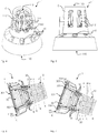
- FIG. 1 1 illustrates an exploded, simplified illustration of a half section of the lighting device 1 according to the invention, with a lighting means 40, a heat distributor 20 connected thereto, a housing 10 connected to the heat distributor 20 and a reflector 30.
- the heat spreader 20 preferably has a trough 201 with a jacket 203 and an end wall 205, wherein the light source 40 bears against the end wall 205.
- the jacket 203 and / or the end wall 205 may be broken at least in places.
- the heat spreader 20 can also be designed as a support wall 205 with cams 207 arranged on it.
- the support wall 205, or end wall can be offset from holes which form the channels 209, in order to allow good ventilation.
- the light-emitting means 40 mounted on the support wall conducts its heat loss to the support wall 205. Due to the thermal coupling of the support wall via the cams to the housing 10, this heat loss is at least partially released to the housing. Another part of the heat loss is given by convection to the ambient air.
- the shell 203 of the trough 201 has two mutually remote shell ends 2031,2032 and outwardly projecting cams 207, wherein between the cam 207 continuous from one to the other shell end 2031,2032 extending channels 209 are present.
- the housing 10 In the assembled state of the lighting device, which is also referred to as a light, the housing 10 abuts against the cam 207.
- the contact surfaces are simplified and not to scale denoted by reference numeral 11.
- the heat loss of the light source 40 is dissipated on the one hand via the cam 207 to the housing 10 and on the other hand to the air flowing through the channels 209.
- the chimney-like configuration of the housing 10 causes an amplification of the air flow or convection. This cooling effect is assisted by the fact that heat loss is transmitted directly to the housing 10 in the region of the abutment surfaces 11.
- the light-emitting means 40 is preferably designed as an LED module with at least one LED and attached to the end wall 205.
- Wörmeleitschn such as thermal grease, an effective heat transfer from the bulb can be achieved on the heat spreader 20.
- FIG. 2 illustrates the heat spreader 20 with arranged thereon illuminant 40 of the inventive lighting device 1 in a plan view.
- Each cam 207 has a width b, which is to an imaginary outer average diameter D of the trough 201 in the ratio of 1/64 to 1/4, preferably in the ratio of 1/32 to 1/8, particularly preferably in the ratio 1/16 ,
- the part of the housing on which the cams 207 abut, may be parallel or inclined to a central axis, not shown, of the housing.
- FIG. 3 Illustrated shows a longitudinal section of the heat spreader along the in FIG. 2 illustrated section line III-III.
- the sheath 203 and / or the end wall 205 may be perforated at least in places to assist in convection.
- a plurality of heat distribution elements 211 which are designed as cooling pins and / or cooling ribs, can be arranged on the end wall 205, opposite the light source 40.
- the heat distribution elements 211 do not directly contact the housing 10, which can, however, be realized by suitable design measures.
- Reference numeral 2050 designates a channel, bore or opening.
- the end wall 205 has at least one such radially inwardly directed channel 2050. This opens into an approximately central mouth 2051 in the end wall 205 to improve the dissipation of heat loss by air. This prevents heat accumulation on the bottom of the end wall and promotes convection.
- Reference numerals 2031 and 2032 designate mutually remote shell ends.
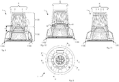
- FIGS. 4 illustrates a perspective view of the inventive lighting device 1, wherein the rear or rear part of the housing is shown broken off, so that the condimentableitopathy 211, which are formed as pins, are visible.
- the reference numeral 2050 designates a channel which opens into the approximately central mouth 2051.
- FIG. 5 illustrates a side view of a composite inventive lighting device 1, with a view of the housing 10.
- the shell of the housing 10 has a plurality of ventilation openings, which support the convection in the housing. Depending on the position of the lighting device, they serve as suction openings or inlet openings and / or outlet openings.
- FIGS. 6 and 7 illustrate a sectional view of a lighting device 1 according to the invention, wherein the elongated arrows K illustrate the natural convection and the wider arrows W heat transfer from the heat spreader 20 to the housing 10.
- the reflector 30 has a light exit opening 301, whose outer opening edge 303 is spaced at least in places from the housing 10, so that an opening, a gap or passage is present.
- a light exit opening 301 whose outer opening edge 303 is spaced at least in places from the housing 10, so that an opening, a gap or passage is present.
- FIG. 7 reference numeral 304 denotes a shutter which is disposed between the opening edge 303 of the reflector and the housing.
- the reflector has a reflector edge 305, in the outer region of the aperture 304 is arranged.
- the reflector edge 305 is also referred to as a collar or flange and may have a planar extension. Both the aperture 304, as well as the reflector edge 305 may at least in places as through holes, slots or the like formed openings, which serve to assist the ventilation of the housing and the dissipation of heat loss.
- FIG. 8 illustrates a plan view of the back of the inventive lighting device 1 with the respective section lines XX, XI-XI and XII-XII.
- FIGS. 9, 10 and 11 illustrate in simplified representation, each a half-section along the section lines of FIG. 8 the elongated arrows K illustrate the natural convection in and through the housing 10 and the wider arrows W heat transfer from the heat spreader 20 to the housing 10.
- openings 110 are present on the casing of the housing 10. These are, for example, designed as elongated or rectangular holes. As opening 110 also the front and rear opening on the housing 10 are understood.
- Reference numeral 1100 designates a gap or opening between the aperture of the reflector and the housing, which extends at least partially along the inner circumference of the housing in this area.
- the gap allows as shown that the designated by arrow K air can flow through this gap in the housing.
- n the length of a cam, that is cam length.
- the cam length of the inventive Lighting device can be related to the mean diameter D, which in FIG. 3 is shown.
- the ratio between n and D is in the range of 2/1 to 1/120, preferably in the range of 1 ⁇ 2 to 1/80, more preferably in the range of 1 ⁇ 2 to 1/10.
- the natural convection in the housing can be supported by an electrically operated, not shown fan.
- the fan can be temperature-controlled.
- the housing is divided into several parts or partial lateral surfaces - here in a rear part 120 and a front part 130.
- the respective parts are conical or designed as a blunt cone.
- the housing shape is not limited to this embodiment, but may consist of a conical part and / or a cylindrical part.
- the cross-sectional area with respect to a section perpendicular to the longitudinal axis of the housing may be round and / or polygonal.
- the cams may extend over the end wall into the region of the possibly existing heat dissipation elements.
- the cams may be formed as a part of the housing, wherein a portion of the cam at least in places on the rear housing part 120 and / or front housing part 130 bear or are connected thereto.
Abstract
Description
- Die Erfindung betrifft eine Leuchteinrichtung gemäss dem Oberbegriff des Anspruchs 1.
- Im Stand der Technik ist die Kühlung von Leuchtmitteln in Leuchten bereits bekannt. So wird in
EP 2208926 A1 ein Leuchtmittelmodul mit einer LED-Bestückung und einem einen Gehäusemantel aufweisenden Gehäuse beschrieben, wobei das Gehäuse mit einem Kühlteil kombiniert ist und wobei das LED-Leuchtmittel auf dem Kühlteil angeordnet ist. Der Gehäusemantel ist kaminartig ausgebildet und oberhalb einer ringförmigen, durch Kühlrippen des Kühlteils unterteilten Öffnung angeordnet, durch welche Luft unterhalb des Leuchtmittels angesaugt werden kann, die dann oberhalb des Leuchtmittels aus dem Gehäuse wieder ausströmt. - Einer der Nachteile dieses Leuchtmittelmoduls besteht darin, dass eine gute Durchlüftung bzw. Durchströmung radial durch das Gehäuse bzw. den Gehäusemantel hindurch durch die flächigen Kühlrippen erschwert wird, insbesondere in geneigter Lage des Leuchtmittelmoduls. Zudem ist nachteilig, dass die flügelartigen Kühlrippen ein erhebliches Volumen beanspruchen und sich weit über den Reflektor hinaus erstrecken, was hinderlich für eine kompakte Bauweise ist.
- Die Aufgabe der Erfindung besteht darin, eine Leuchteinrichtung vorzuschlagen, welche die Nachteile des Stands der Technik nicht aufweist. Insbesondere soll mittels natürlicher Konvektion eine effektive Kühlung der Leuchteinrichtung erfolgen.
- Erfindungsgemäss wird die Aufgabe gelöst durch eine Leuchteinrichtung gemäss dem kennzeichnenden Teil von Anspruch 1.
- Einer der Vorteile der Erfindung besteht darin, dass die Verlustwärme des Leuchtmittels einerseits über die Nocken an das Gehäuse und andererseits an durch die Kanäle strömende Luft abgeführt wird. Die kaminartige Ausgestaltung des Gehäuses bewirkt eine Verstärkung der Luftströmung bzw. Konvektion, was hier auch als Kamineffekt bezeichnet ist. Dieser Kühleffekt wird unterstützt dadurch, dass Verlustwärme direkt an das Gehäuse im Bereich der Anliegeflächen übertragen wird.
- Ein anderer Vorteil der Erfindung besteht darin, dass die erfindungsgemässe Ausgestaltung der Leuchteinrichtung in verschiedenen Lagen oder Positionen wirksam ist, da eine Staubildung von Luft verhindert wird, indem der Kamineffekt nicht nur in Längsrichtung des Gehäuses sondern auch im vorderen und hinteren Teil des Gehäuses wirkt.
- Vorteilhafte Weiterbildungen der Erfindung sind in den abhängigen Ansprüchen angegeben.
- In einer Ausführungsform der Erfindung ist das Leuchtmittel als LED-Modul mit mindestens einer LED ausgebildet ist und an der Endwand befestigt.
- Einer der Vorteile der Erfindung besteht darin, dass ein Leuchtmittel mit einer langen Lebensdauer und vorteilhaften Lichteigenschaften in besonders kompakter Bauweise mit der als Trägermodul wirkenden Endwand des Wärmeverteilers direkt verbunden ist.
- In einer anderen Ausführungsform der Erfindung sind an der Endwand gegenüberliegend zum Leuchtmittel mehrere Wärmeverteilelemente, welche als Kühlstifte und/oder Kühlrippen ausgebildet sind, angeordnet.
- Einer der Vorteile der Erfindung besteht darin, dass Leuchtmittel-spezifisch ein entsprechender Wärmeverteiler selektiert bzw. hergestellt werden kann, wobei Kühlstifte und/oder Kühlrippen die Wärmeverteilung an die Umgebungsluft verstärken.
- In einer weiteren Ausführungsform der Erfindung weist die Endwand mindestens einen radial nach innen gerichteten Kanal auf, welche in mindestens eine Mündung in der Endwand mündet, wobei die Mündung vorzugsweise ungefähr zentral in der Endwand angeordnet ist.
- Einer der Vorteile der Erfindung besteht darin, dass das Abführen von Verlustwärme durch Luft dadurch verbessert und die Bildung von Wärmestaus verhindert wird.
- In einer Ausführungsform der Erfindung ragt der Reflektor in die Wanne hinein und/oder der Reflektor ragt mindestens teilweise in das Gehäuse hinein.
- Einer der Vorteile der Erfindung besteht darin, dass die Leuchteinrichtung in einer kompakten Bauweise realisierbar ist, wobei die Kühlung des Leuchtmittels bzw. das Abführen von Verlustwärme dennoch effizient ist. Der beschriebene Kamineffekt ist dabei stets gewährleistet.
- In einer anderen Ausführungsform der Erfindung weist jeder Nocken eine Breite b auf, welche zu einem gedachten äusseren mittleren Durchmesser D der Wanne derart im Verhältnis steht, dass wirksam Verlustwärme des Leuchtmittels über die Nocken an das Gehäuse und an durch die Kanäle strömende Luft abgeführt werden kann, so dass beide Effekte vorteilhaft kombiniert sind.
- In einer weiteren Ausführungsform der Erfindung ist der Mantel und/oder ist die Endwand mindestens stellenweise durchbrochen.
- Einer der Vorteile der Erfindung besteht darin, dass mittels Bohrungen, Löchern, eine verstärkte Konvektion erzielt werden kann.
- In einer Ausführungsform der Erfindung ist das Gehäuse durch Press-und/oder Füge- und/oder Kaltdehn- und/oder Eindehn- und/oder Klebverbindung mit dem Wärmeverteiler verbunden.
- Einer der Vorteile der Erfindung besteht darin, dass insbesondere die Wärmeübertragung vom Wärmeverteiler an das Gehäuse durch die genannte Verbindungsart erhöht wird.
- In einer anderen Ausführungsform der Erfindung weist der Reflektor eine Lichtaustrittsöffnung auf, deren äusserer Öffnungsrand mindestens stellenweise vom Gehäuse beabstandet ist.
- Einer der Vorteile der Erfindung besteht darin, dass durch Ein- und/oder Ausströmen von Luft die natürliche Luftumströmung im Gehäuse in verschiedenen Befestigungspositionen der Leuchteinrichtung gefördert wird.
- In einer weiteren Ausführungsform der Erfindung ist der Wärmeverteiler aus Leichtmetall, insbesondere Aluminium, gebildet. Der Wärmeverteiler mit Wanne, Nocken und/oder Wärmeverteilelementen kann im Druckgussverfahren hergestellt werden. Ein Nachbearbeiten des druckgegossenen Wärmeverteilers, insbesondere der Endwand, Nocken, Bohrungen und/oder Wärmeleitelemente ist mit bekannten Bearbeitungsmethoden möglich. Der Wärmeverteiler kann nachträglich zudem zur verbesserten Wärmeleitung oberflächenbehandelt werden.
- Einer der Vorteile der Erfindung ist, dass das Gehäuse aus einem Metall oder nicht metallischen Material gebildet sein kann, so ein breiter Gestaltungsspielraum bei der Wahl von Gehäuseformen und/oder Gehäusematerialien möglich ist, wobei stets eine effektive Wärmeableitung mittels des Wärmeverteilers gewährleistet ist.
- Im Folgenden werden bevorzugte Ausführungsbeispiele der Erfindung anhand von Figuren näher erläutert.
-
Fig. 1 zeigt in eine explodierte, vereinfachte Darstellung eines Halbschnitts der erfindungsgemässen Leuchteinrichtung, mit Gehäuse, mit Reflektor und mit Wärmeverteiler, an welchem ein Leuchtmittel angeordnet ist; -
Fig. 2 zeigt den Wärmeverteiler mit daran angeordnetem Leuchtmittel der erfindungsgemässen Leuchteinrichtung in einer Aufsicht; -
Fig. 3 zeigt einen Längsschnitt des Wärmeverteilers entlang der inFig. 2 dargestellten Schnittlinie III-III; -
Fig. 4 zeigt eine perspektivische Ansicht auf die erfindungsgemässe Leuchteinrichtung 1, wobei der rückwärtige oder hintere Teil des Gehäuses abgebrochen dargestellt ist; -
Fig. 5 zeigt eine Seitenansicht einer zusammengesetzten erfindungsgemässen Leuchteinrichtung, mit Sicht auf das Gehäuse; -
Fig. 6 und Fig. 7 zeigen eine geschnittene Darstellung einer erfindungsgemässen Leuchteinrichtung, wobei die länglichen Pfeile die natürliche Konvektion und die breiteren Pfeile die Wärmeübertragung vom Wärmeverteiler auf das Gehäuse veranschaulichen; -
Fig. 8 zeigt eine Aufsicht auf die Rückseite der erfindungsgemässen Leuchteinrichtung mit den jeweiligen Schnittlinien X-X, XI-XI sowie XII-XII und -
Fig. 9, 10 und 11 zeigen in vereinfachter Darstellung je einen Halbschnitt entlang den Schnittlinien vonFig. 8 gezeigten Schnittlinien, wobei die länglichen Pfeile die natürliche Konvektion und die breiteren Pfeile die Wärmeübertragung vom Wärmeverteiler auf das Gehäuse veranschaulichen. -
Figur 1 illustriert eine explodierte, vereinfachte Darstellung eines Halbschnitts der erfindungsgemässen Leuchteinrichtung 1, mit einem Leuchtmittel 40, einem mit diesem verbunden Wärmeverteiler 20, einem mit dem Wärmeverteiler 20 verbundenen Gehäuse 10 sowie einem Reflektor 30. - Der Wärmeverteiler 20 weist vorzugsweise eine Wanne 201 mit einem Mantel 203 und einer Endwand 205 auf, wobei das Leuchtmittel 40 an der Endwand 205 anliegt. Der Mantel 203 und/oder die Endwand 205 können mindestens stellenweise durchbrochen sein. Der Wärmeverteiler 20 kann auch als Trägerwand 205 mit an dieser angeordneten Nocken 207 ausgebildet sein. Die Trägerwand 205, bzw. Endwand, kann dabei von Bohrungen versetzt sein, welche die Kanäle 209 bilden, um eine gute Durchlüftung zu ermöglichen. Das auf der Trägerwand montierte Leuchtmittel 40 leitet dessen Verlustwärme an die Trägerwand 205 ab. Durch die thermische Kopplung der Trägerwand über die Nocken an das Gehäuse 10 wird diese Verlustwärme mindestens teilweise an das Gehäuse abgegeben. Ein anderer Teil der Verlustwärme wird durch Konvektion an die Umgebungsluft abgegeben.
- Der Mantel 203 der Wanne 201 weist zwei einander abgewandte Mantelenden 2031,2032 und nach aussen ragende Nocken 207 auf, wobei zwischen den Nocken 207 durchgehende vom einen zum andern Mantelende 2031,2032 verlaufende Kanäle 209 vorhanden sind. In zusammengesetztem Zustand der Leuchteinrichtung, welche auch als Leuchte bezeichnet wird, liegt das Gehäuse 10 an den Nocken 207 an. Die Anliegeflächen sind vereinfacht und nicht massstäblich mit Bezugszeichen 11 bezeichnet.
- Die Verlustwärme des Leuchtmittels 40 wird einerseits über die Nocken 207 an das Gehäuse 10 und andererseits an durch die Kanäle 209 strömende Luft abgeführt. Die kaminartige Ausgestaltung des Gehäuses 10 bewirkt eine Verstärkung der Luftströmung bzw. Konvektion. Dieser Kühleffekt wird unterstützt dadurch, dass Verlustwärme direkt an das Gehäuse 10 im Bereich der Anliegeflächen 11 übertragen wird.
- Beim Leuchtmittel entstehen bei der Energieumsetzung in Licht je nach Wirkungsgrad Verluste verschiedener Art. Die Summe der verlorenen Energie wird als Verlustwärme verstanden. Das Leuchtmittel 40 ist vorzugsweise als LED-Modul mit mindestens einer LED ausgebildet ist und an der Endwand 205 befestigt. Mittels Wörmeleitmitteln, etwa Wärmeleitpaste, kann eine effektive Wärmeübertragung vom Leuchtmittel auf den Wärmeverteiler 20 erzielt werden.
-
Figur 2 illustriert den Wärmeverteiler 20 mit daran angeordnetem Leuchtmittel 40 der erfindungsgemässen Leuchteinrichtung 1 in einer Aufsicht. Jeder Nocken 207 weist eine Breite b auf, welche zu einem gedachten äusseren mittleren Durchmesser D der Wanne 201 im Verhältnis von 1/64 bis 1/4, vorzugsweise im Verhältnis 1/32 bis 1/8, besonders bevorzugt im Verhältnis 1/16 ist. Der Teil des Gehäuses, an welchem die Nocken 207 anliegen, kann zu einer nicht dargestellten Mittelachse des Gehäuses parallel oder geneigt sein. -
Figur 3 illustriert zeigt einen Längsschnitt des Wärmeverteilers entlang der inFigur 2 dargestellten Schnittlinie III-III. Der Mantel 203 und/oder die Endwand 205 können mindestens stellenweise durchbrochen sein, um die Konvektion zu unterstützen. Zu besseren Verteilung von Verlustwärme können an der Endwand 205 gegenüberliegend zum Leuchtmittel 40 mehrere Wärmeverteilelemente 211, welche als Kühlstifte und/oder Kühlrippen ausgebildet sind, angeordnet sein. In der gezeigten Ausführungsform berühren die Wärmeverteilelemente 211 das Gehäuse 10 nicht direkt, was durch geeignete konstruktive Massnahmen jedoch realisierbar ist. - Mit Bezugszeichen 2050 ist ein Kanal, Bohrung oder Öffnung bezeichnet. Die Endwand 205 weist mindestens einen solchen radial nach innen gerichteten Kanal 2050 auf. Dieser mündet in eine ungefähr zentrale Mündung 2051 in der Endwand 205, um das Abführen von Verlustwärme durch Luft zu verbessern. So kann ein Wärmestau auf dem Grund der Endwand verhindert und die Konvektion unterstützt werden. Es können bspw. sternartig mehrere Kanäle vorhanden sein, wobei jeder Kanal in eine einzige zentrale Mündung und/oder in eine kanalspezifische Mündung mündet. Die Bezugszeichen 2031 und 2032 bezeichnen einander abgewandte Mantelenden.
-
Figuren 4 illustriert eine perspektivische Ansicht auf die erfindungsgemässe Leuchteinrichtung 1, wobei der rückwärtige oder hintere Teil des Gehäuses abgebrochen dargestellt ist, so dass die Wärmeableitelemente 211, welche als Stifte ausgebildet sind, ersichtlich sind. Das Bezugszeichen 2050 bezeichnet einen Kanal, welcher in die ungefähr zentrale Mündung 2051 mündet. -
Figur 5 illustriert eine Seitenansicht einer zusammengesetzten erfindungsgemässen Leuchteinrichtung 1, mit Sicht auf das Gehäuse 10. Der Mantel des Gehäuses 10 weist mehrere Lüftungsöffnungen auf, welche die Konvektion im Gehäuse unterstützen. Sie dienen je nach Lage der Leuchteinrichtung als Ansaugöffnungen bzw. Einlassöffnungen und/oder Auslassöffnungen. -
Figuren 6 und 7 illustrieren eine geschnittene Darstellung einer erfindungsgemässen Leuchteinrichtung 1, wobei die länglichen Pfeile K die natürliche Konvektion und die breiteren Pfeile W die Wärmeübertragung vom Wärmeverteiler 20 auf das Gehäuse 10 veranschaulichen. - Aus den Figuren ist ersichtlich, dass der Reflektor 30 eine Lichtaustrittsöffnung 301 aufweist, deren äusserer Öffnungsrand 303 mindestens stellenweise vom Gehäuse 10 beabstandet ist, so dass eine Öffnung, ein Spalt oder Durchgang vorhanden ist. Durch wird Ein- und/oder Ausströmen von Luft die natürliche Luftumströmung im Gehäuse 10 in verschiedenen Befestigungspositionen der Leuchteinrichtung gefördert.
-
Figur 7 bezeichnet mit Bezugszeichen 304 eine Blende, welche zwischen dem Öffnungsrand 303 des Reflektors und dem Gehäuse angeordnet ist. Der Reflektor weist einen Reflektorrand 305 auf, in dessen äusseren Bereich die Blende 304 angeordnet ist. Der Reflektorrand 305 wird auch als Kragen oder Flansch bezeichnet und kann eine flächige Ausdehnung aufweisen. Sowohl der die Blende 304, wie auch der Reflektorrand 305 können mindestens stellenweise als Durchgangsbohrungen, Schlitze oder dergleichen ausgebildete Öffnungen aufweisen, welche zur Unterstützung der Durchlüftung des Gehäuses und dem Abführen von Verlustwärme dienen. -
Figur 8 illustriert eine Aufsicht auf die Rückseite der erfindungsgemässen Leuchteinrichtung 1 mit den jeweiligen Schnittlinien X-X, XI-XI sowie XII-XII. -
Figuren 9, 10 und 11 illustrieren in vereinfachter Darstellung je einen Halbschnitt entlang den Schnittlinien vonFigur 8 gezeigten Schnittlinien, wobei die länglichen Pfeile K die natürliche Konvektion im bzw. durch das Gehäuse 10 und die breiteren Pfeile W die Wärmeübertragung vom Wärmeverteiler 20 auf das Gehäuse 10 veranschaulichen. - Um eine gute Durchlüftung oder Luftströmung durch das Gehäuse 10 zu gewährleisten, sind am Mantel des Gehäuses 10 mehrere Öffnungen 110 vorhanden. Diese sind bspw. als längliche oder rechteckige Löcher ausgebildet. Als Öffnung 110 werden ebenfalls die vordere und hintere Öffnung am Gehäuse 10 verstanden.
- Mit Bezugszeichen 1100 ist ein Spalt oder eine Öffnung zwischen der Blende des Reflektors und dem Gehäuse bezeichnet, welcher sich mindestens teilweise entlang des inneren Umfangs des Gehäuses in diesem Bereich erstreckt. Der Spalt ermöglicht wie dargestellt, dass die mit Pfeil K bezeichnete Luft durch diesen Spalt in das Gehäuse einströmen kann.
- In
Figur 9 ist mit Bezugszeichen n die Länge eines Nockens, sprich Nockenlänge, bezeichnet. Die Nockenlänge der erfindungsgemässen Leuchteinrichtung kann in Bezug gebracht werden zum mittleren Durchmesser D, welcher inFigur 3 gezeigt ist. Hiernach ist das Verhältnis zwischen n und D im Bereich von 2/1 bis 1/120, bevorzugt im Bereich von ½ bis 1/80, besonders bevorzugt im Bereich von ½ bis 1/10. - Die natürliche Konvektion im Gehäuse kann durch einen elektrisch betriebenen, hier nicht dargestellten Lüfter unterstützt werden. Der Lüfter kann temperaturabhängig gesteuert sein.
- In den dargestellten Ausführung der erfindungsgemässen Leuchteinrichtung, welche auch als Leuchte bezeichnet wird, ist das Gehäuse in mehrere Teile oder Teilmantelflächen unterteilt - hier in einen hinteren Teil 120 und einen vorderen Teil 130. Die Begrifflichkeiten "vorne" und "hinten" werden bezüglich der Anordnung des Leuchtmittels verstanden.
- Die jeweiligen Teile sind konisch bzw. als stumpfe Kegel ausgebildet. Die Gehäuseform ist jedoch nicht auf diese Ausbildung beschränkt, sondern kann aus einem konischen Teil und/oder aus einem zylindrischen Teil bestehen. Die Querschnittsfläche bezüglich eines Schnitts rechtwinklig zur Längsachse des Gehäuses kann rund und/oder polygonal ausgebildet sein.
- Die Nocken können sich über die Endwand in den Bereich der allenfalls vorhandenen Wärmeableitelemente erstrecken. Dabei können die Nocken als ein Teil des Gehäuses ausgebildet sein, wobei ein Abschnitt der Nocken mindestens stellenweise am hinteren Gehäuseteil 120 und/oder vorderen Gehäuseteil 130 anliegen bzw. mit diesem verbunden sind.
-
- 1
- Beleuchtungseinheit, Leuchteinrichtung
- 10
- Gehäuse
- 11
- Anliegebereich, Anliegefläche
- 100
- Rippe, Steg, Kühlrippe
- 110
- Gehäuseöffnung
- 1100
- Spalt, Öffnung, Zwischenraum
- 120
- Gehäuseteil
- 130
- Gehäuseteil
- 20
- Wärmeverteiler, Kühlkörper
- 201
- Wanne
- 203
- Mantel
- 2031
- Mantelende
- 2032
- Mantelende
- 205
- Endwand
- 2050
- Kanal, Bohrung
- 2051
- Mündung
- 207
- Nocken, Rippe
- 209
- Kanal, Nut
- 211
- Wärmeableitelement
- 30
- Reflektor
- 301
- Lichtaustrittsöffnung
- 303
- Öffnungsrand
- 304
- Blende
- 305
- Reflektorrand, Flansch, Kragen
- 40
- Leuchtmittel, LED-Modul
- b
- Breite, Nockenbreite
- D
- Durchmesser
- K
- Pfeil
- n
- Länge, Nockenlänge
- W
- Pfeil
Claims (12)
- Leuchteinrichtung (1), mit einem Leuchtmittel (40), einem mit diesem verbunden Wärmeverteiler (20), einem mit dem Wärmeverteiler (20) verbundenen Gehäuse (10) sowie einem Reflektor (30), dadurch gekennzeichnet,
dass der Wärmeverteiler (20) eine Wanne (201) mit einem Mantel (203) und einer Endwand (205) aufweist, wobei das Leuchtmittel (40) an der Endwand (205) anliegt,
dass der Mantel (203) der Wanne (201) zwei einander abgewandte Mantelenden (2031,2032) und nach aussen ragende Nocken (207) aufweist,
dass zwischen den Nocken (207) durchgehende vom einen zum andern Mantelende (2031,2032) verlaufende Kanäle (209) vorhanden sind und dass das Gehäuse (10) an den Nocken (207) anliegt, um Verlustwärme des Leuchtmittels über die Nocken an das Gehäuse und an durch die Kanäle strömende Luft abzuführen. - Leuchteinrichtung (1) gemäss einem der vorgenannten Ansprüche, dadurch gekennzeichnet, dass das Leuchtmittel (40) als LED-Modul mit mindestens einer LED ausgebildet ist und an der Endwand (205) befestigt ist.
- Leuchteinrichtung (1) gemäss einem der vorgenannten Ansprüche, dadurch gekennzeichnet, dass an der Endwand (205) gegenüberliegend zum Leuchtmittel (40) mehrere Wärmeverteilelemente (211), welche als Kühlstifte und/oder Kühlrippen ausgebildet sind, angeordnet sind.
- Leuchteinrichtung (1) gemäss einem der vorgenannten Ansprüche, dadurch gekennzeichnet, dass die Endwand (205) mindestens eine radial nach innen gerichteten Kanal (2050) aufweist, welcher in mindestens eine Mündung (2051) in der Endwand (205) mündet, um das Abführen von Verlustwärme durch Luft zu verbessern.
- Leuchteinrichtung (1) gemäss einem der vorgenannten Ansprüche, dadurch gekennzeichnet, dass der Reflektor (30) in die Wanne (201) hineinragt.
- Leuchteinrichtung (1) gemäss einem der vorgenannten Ansprüche, dadurch gekennzeichnet, dass der Reflektor (30) mindestens teilweise in das Gehäuse (10) hineinragt.
- Leuchteinrichtung (1) gemäss einem der vorgenannten Ansprüche, dadurch gekennzeichnet, dass jeder Nocken (207) eine Breite b aufweist, welche zu einem gedachten äusseren mittleren Durchmesser D der Wanne (201) im Verhältnis von 1/64 bis 1/4, vorzugsweise im Verhältnis 1/32 bis 1/8, besonders bevorzugt im Verhältnis 1 /16 ist.
- Leuchteinrichtung (1) gemäss einem der vorgenannten Ansprüche, dadurch gekennzeichnet, dass der Mantel (203) und/oder die Endwand (205) mindestens stellenweise durchbrochen sind.
- Leuchteinrichtung (1) gemäss einem der vorgenannten Ansprüche, dadurch gekennzeichnet, dass das Gehäuse (10) durch Press- und/oder Füge-und/oder Kaltdehn- und/oder Eindehn- und/oder Klebverbindung mit dem Wärmeverteiler (20) verbunden ist.
- Leuchteinrichtung (1) gemäss einem der vorgenannten Ansprüche, dadurch gekennzeichnet, dass der Reflektor (30) eine Lichtaustrittsöffnung (301) aufweist, deren äusserer Öffnungsrand (303) mindestens stellenweise vom Gehäuse (10) beabstandet ist, derart, dass durch Ein- oder Ausströmen von Luft die natürliche Luftumströmung im Gehäuse (10) gefördert wird.
- Leuchteinrichtung (1) gemäss einem der vorgenannten Ansprüche, dadurch gekennzeichnet, dass der Wärmeverteiler (20) aus Leichtmetall, insbesondere Aluminium, gebildet ist.
- Leuchteinrichtung (1) gemäss einem der vorgenannten Ansprüche, dadurch gekennzeichnet, dass der Wärmeverteiler (20) im Druckgussverfahren herstellbar ist.
Applications Claiming Priority (1)
| Application Number | Priority Date | Filing Date | Title |
|---|---|---|---|
| CH00304/11A CH704544A1 (de) | 2011-02-22 | 2011-02-22 | Leuchteinrichtung mit Wärmeverteiler. |
Publications (2)
| Publication Number | Publication Date |
|---|---|
| EP2492589A1 true EP2492589A1 (de) | 2012-08-29 |
| EP2492589B1 EP2492589B1 (de) | 2016-04-27 |
Family
ID=44454010
Family Applications (1)
| Application Number | Title | Priority Date | Filing Date |
|---|---|---|---|
| EP12155711.0A Active EP2492589B1 (de) | 2011-02-22 | 2012-02-16 | Leuchteinrichtung mit Wärmeverteiler |
Country Status (2)
| Country | Link |
|---|---|
| EP (1) | EP2492589B1 (de) |
| CH (1) | CH704544A1 (de) |
Cited By (4)
| Publication number | Priority date | Publication date | Assignee | Title |
|---|---|---|---|---|
| CN104180352A (zh) * | 2013-05-24 | 2014-12-03 | 深圳市海洋王照明工程有限公司 | 大功率灯具 |
| GB2517064A (en) * | 2013-06-14 | 2015-02-11 | Aurora Ltd | Improved lighting unit |
| WO2015133196A1 (ja) * | 2014-03-03 | 2015-09-11 | 株式会社アイ・ライティング・システム | 照明器具及びled光源ユニット |
| JP2015167130A (ja) * | 2015-02-20 | 2015-09-24 | 株式会社アイ・ライティング・システム | 照明器具及びled光源ユニット |
Citations (5)
| Publication number | Priority date | Publication date | Assignee | Title |
|---|---|---|---|---|
| DE202008006327U1 (de) * | 2007-12-04 | 2008-07-17 | Cooler Master Co., Ltd., Chung-Ho City | Lampe mit Wärmeaufbau sowie zugehörige Lampenabdeckung |
| DE202008006325U1 (de) * | 2007-11-28 | 2008-07-17 | Cooler Master Co., Ltd., Chung-Ho City | Wärmeabführanordnung und Lampe mit dieser |
| WO2010066841A1 (en) * | 2008-12-11 | 2010-06-17 | Ledned Holding B.V. | Led lamp system |
| EP2208926A1 (de) | 2009-01-16 | 2010-07-21 | RD System-Leuchten AG | Leuchtmittelmodul mit einer LED-Bestückung |
| US20100237760A1 (en) * | 2009-03-17 | 2010-09-23 | Intematix Corporation | LED Based Lamp |
Family Cites Families (2)
| Publication number | Priority date | Publication date | Assignee | Title |
|---|---|---|---|---|
| US7766512B2 (en) * | 2006-08-11 | 2010-08-03 | Enertron, Inc. | LED light in sealed fixture with heat transfer agent |
| KR100902631B1 (ko) * | 2008-10-24 | 2009-06-12 | 현대통신 주식회사 | 나노스프레더를 이용한 원형구조의 led 발광 조명등 |
-
2011
- 2011-02-22 CH CH00304/11A patent/CH704544A1/de not_active Application Discontinuation
-
2012
- 2012-02-16 EP EP12155711.0A patent/EP2492589B1/de active Active
Patent Citations (5)
| Publication number | Priority date | Publication date | Assignee | Title |
|---|---|---|---|---|
| DE202008006325U1 (de) * | 2007-11-28 | 2008-07-17 | Cooler Master Co., Ltd., Chung-Ho City | Wärmeabführanordnung und Lampe mit dieser |
| DE202008006327U1 (de) * | 2007-12-04 | 2008-07-17 | Cooler Master Co., Ltd., Chung-Ho City | Lampe mit Wärmeaufbau sowie zugehörige Lampenabdeckung |
| WO2010066841A1 (en) * | 2008-12-11 | 2010-06-17 | Ledned Holding B.V. | Led lamp system |
| EP2208926A1 (de) | 2009-01-16 | 2010-07-21 | RD System-Leuchten AG | Leuchtmittelmodul mit einer LED-Bestückung |
| US20100237760A1 (en) * | 2009-03-17 | 2010-09-23 | Intematix Corporation | LED Based Lamp |
Cited By (5)
| Publication number | Priority date | Publication date | Assignee | Title |
|---|---|---|---|---|
| CN104180352A (zh) * | 2013-05-24 | 2014-12-03 | 深圳市海洋王照明工程有限公司 | 大功率灯具 |
| GB2517064A (en) * | 2013-06-14 | 2015-02-11 | Aurora Ltd | Improved lighting unit |
| GB2517064B (en) * | 2013-06-14 | 2020-04-15 | Aurora Ltd | Improved lighting unit |
| WO2015133196A1 (ja) * | 2014-03-03 | 2015-09-11 | 株式会社アイ・ライティング・システム | 照明器具及びled光源ユニット |
| JP2015167130A (ja) * | 2015-02-20 | 2015-09-24 | 株式会社アイ・ライティング・システム | 照明器具及びled光源ユニット |
Also Published As
| Publication number | Publication date |
|---|---|
| EP2492589B1 (de) | 2016-04-27 |
| CH704544A1 (de) | 2012-08-31 |
Similar Documents
| Publication | Publication Date | Title |
|---|---|---|
| EP2556296B1 (de) | Leuchtengehäuse | |
| EP2394096A1 (de) | Kühlkörper für eine leuchtvorrichtung | |
| DE102014202759A1 (de) | Halbleiter-Röhrenlampe | |
| DE102012222184A1 (de) | Leuchte mit Luftleitflächen | |
| EP2492589B1 (de) | Leuchteinrichtung mit Wärmeverteiler | |
| DE202013100167U1 (de) | Lampe mit hoher Kühlwirkung | |
| EP2407713B1 (de) | LED-Leuchte mit Kühlkörper | |
| EP2647907B1 (de) | Leuchteneinsatz mit reflektor | |
| DE102011081369A1 (de) | Leuchte, insbesondere LED-Leuchte mit passiver Kühlung | |
| DE102008003703A1 (de) | Leuchte mit einem Leuchtengehäuse in Form eines Hohlprofils | |
| EP3911892B1 (de) | Leuchte mit umfangsseitig geschlossenem kühlkörper | |
| DE202011003010U1 (de) | Leuchte mit passiver Kühlung | |
| DE102009051334A1 (de) | LED-Lampe mit Kühlkörper | |
| DE202011000220U1 (de) | LED-Leuchte, insbesondere für Aquarien, Terrarien oder dergleichen | |
| DE202008004795U1 (de) | Wohnraumleuchte | |
| DE202006004833U1 (de) | Lampenreflektor mit Kühlkörper | |
| DE202008000360U1 (de) | Leuchte mit einem Leuchtgehäuse in Form eines Hohlprofils | |
| EP2530377B1 (de) | Kühlsystem für eine Leuchte | |
| DE102010010649B4 (de) | Leuchte für die Raumbeleuchtung | |
| DE102012005874A1 (de) | Vorrichtung zur Enttauung einer Beleuchtungseinheit und Beleuchtungseinheit mit einer solchen Vorrichtung | |
| EP2372229A1 (de) | Downlightreflektor mit Zusatzlichtquelle | |
| DE202012103988U1 (de) | Lampeneinheit für eine Leuchte | |
| DE102008006535A1 (de) | Leuchte | |
| DE202010012962U1 (de) | Wärmeableitanordnung eines LED-Lampengehäuses | |
| EP3244128A1 (de) | Leuchte |
Legal Events
| Date | Code | Title | Description |
|---|---|---|---|
| PUAI | Public reference made under article 153(3) epc to a published international application that has entered the european phase |
Free format text: ORIGINAL CODE: 0009012 |
|
| AK | Designated contracting states |
Kind code of ref document: A1 Designated state(s): AL AT BE BG CH CY CZ DE DK EE ES FI FR GB GR HR HU IE IS IT LI LT LU LV MC MK MT NL NO PL PT RO RS SE SI SK SM TR |
|
| AX | Request for extension of the european patent |
Extension state: BA ME |
|
| 17P | Request for examination filed |
Effective date: 20130228 |
|
| REG | Reference to a national code |
Ref country code: DE Ref legal event code: R079 Ref document number: 502012006862 Country of ref document: DE Free format text: PREVIOUS MAIN CLASS: F21V0029000000 Ipc: F21V0029710000 |
|
| RIC1 | Information provided on ipc code assigned before grant |
Ipc: F21V 29/77 20150101ALI20151113BHEP Ipc: F21V 29/00 20150101ALI20151113BHEP Ipc: F21K 99/00 20100101ALI20151113BHEP Ipc: F21V 29/71 20150101AFI20151113BHEP Ipc: F21V 29/74 20150101ALI20151113BHEP Ipc: F21V 29/80 20150101ALI20151113BHEP |
|
| GRAP | Despatch of communication of intention to grant a patent |
Free format text: ORIGINAL CODE: EPIDOSNIGR1 |
|
| INTG | Intention to grant announced |
Effective date: 20160113 |
|
| GRAS | Grant fee paid |
Free format text: ORIGINAL CODE: EPIDOSNIGR3 |
|
| GRAA | (expected) grant |
Free format text: ORIGINAL CODE: 0009210 |
|
| AK | Designated contracting states |
Kind code of ref document: B1 Designated state(s): AL AT BE BG CH CY CZ DE DK EE ES FI FR GB GR HR HU IE IS IT LI LT LU LV MC MK MT NL NO PL PT RO RS SE SI SK SM TR |
|
| REG | Reference to a national code |
Ref country code: GB Ref legal event code: FG4D Free format text: NOT ENGLISH |
|
| REG | Reference to a national code |
Ref country code: CH Ref legal event code: EP |
|
| REG | Reference to a national code |
Ref country code: AT Ref legal event code: REF Ref document number: 795237 Country of ref document: AT Kind code of ref document: T Effective date: 20160515 |
|
| REG | Reference to a national code |
Ref country code: IE Ref legal event code: FG4D Free format text: LANGUAGE OF EP DOCUMENT: GERMAN |
|
| REG | Reference to a national code |
Ref country code: CH Ref legal event code: NV Representative=s name: BRAUNPAT BRAUN EDER AG, CH |
|
| REG | Reference to a national code |
Ref country code: DE Ref legal event code: R096 Ref document number: 502012006862 Country of ref document: DE |
|
| REG | Reference to a national code |
Ref country code: LT Ref legal event code: MG4D |
|
| REG | Reference to a national code |
Ref country code: NL Ref legal event code: MP Effective date: 20160427 |
|
| PG25 | Lapsed in a contracting state [announced via postgrant information from national office to epo] |
Ref country code: NL Free format text: LAPSE BECAUSE OF FAILURE TO SUBMIT A TRANSLATION OF THE DESCRIPTION OR TO PAY THE FEE WITHIN THE PRESCRIBED TIME-LIMIT Effective date: 20160427 |
|
| PG25 | Lapsed in a contracting state [announced via postgrant information from national office to epo] |
Ref country code: LT Free format text: LAPSE BECAUSE OF FAILURE TO SUBMIT A TRANSLATION OF THE DESCRIPTION OR TO PAY THE FEE WITHIN THE PRESCRIBED TIME-LIMIT Effective date: 20160427 Ref country code: PL Free format text: LAPSE BECAUSE OF FAILURE TO SUBMIT A TRANSLATION OF THE DESCRIPTION OR TO PAY THE FEE WITHIN THE PRESCRIBED TIME-LIMIT Effective date: 20160427 Ref country code: NO Free format text: LAPSE BECAUSE OF FAILURE TO SUBMIT A TRANSLATION OF THE DESCRIPTION OR TO PAY THE FEE WITHIN THE PRESCRIBED TIME-LIMIT Effective date: 20160727 Ref country code: FI Free format text: LAPSE BECAUSE OF FAILURE TO SUBMIT A TRANSLATION OF THE DESCRIPTION OR TO PAY THE FEE WITHIN THE PRESCRIBED TIME-LIMIT Effective date: 20160427 |
|
| PG25 | Lapsed in a contracting state [announced via postgrant information from national office to epo] |
Ref country code: HR Free format text: LAPSE BECAUSE OF FAILURE TO SUBMIT A TRANSLATION OF THE DESCRIPTION OR TO PAY THE FEE WITHIN THE PRESCRIBED TIME-LIMIT Effective date: 20160427 Ref country code: LV Free format text: LAPSE BECAUSE OF FAILURE TO SUBMIT A TRANSLATION OF THE DESCRIPTION OR TO PAY THE FEE WITHIN THE PRESCRIBED TIME-LIMIT Effective date: 20160427 Ref country code: SE Free format text: LAPSE BECAUSE OF FAILURE TO SUBMIT A TRANSLATION OF THE DESCRIPTION OR TO PAY THE FEE WITHIN THE PRESCRIBED TIME-LIMIT Effective date: 20160427 Ref country code: ES Free format text: LAPSE BECAUSE OF FAILURE TO SUBMIT A TRANSLATION OF THE DESCRIPTION OR TO PAY THE FEE WITHIN THE PRESCRIBED TIME-LIMIT Effective date: 20160427 Ref country code: RS Free format text: LAPSE BECAUSE OF FAILURE TO SUBMIT A TRANSLATION OF THE DESCRIPTION OR TO PAY THE FEE WITHIN THE PRESCRIBED TIME-LIMIT Effective date: 20160427 Ref country code: GR Free format text: LAPSE BECAUSE OF FAILURE TO SUBMIT A TRANSLATION OF THE DESCRIPTION OR TO PAY THE FEE WITHIN THE PRESCRIBED TIME-LIMIT Effective date: 20160728 Ref country code: PT Free format text: LAPSE BECAUSE OF FAILURE TO SUBMIT A TRANSLATION OF THE DESCRIPTION OR TO PAY THE FEE WITHIN THE PRESCRIBED TIME-LIMIT Effective date: 20160829 |
|
| PG25 | Lapsed in a contracting state [announced via postgrant information from national office to epo] |
Ref country code: IT Free format text: LAPSE BECAUSE OF FAILURE TO SUBMIT A TRANSLATION OF THE DESCRIPTION OR TO PAY THE FEE WITHIN THE PRESCRIBED TIME-LIMIT Effective date: 20160427 |
|
| REG | Reference to a national code |
Ref country code: DE Ref legal event code: R097 Ref document number: 502012006862 Country of ref document: DE |
|
| PG25 | Lapsed in a contracting state [announced via postgrant information from national office to epo] |
Ref country code: RO Free format text: LAPSE BECAUSE OF FAILURE TO SUBMIT A TRANSLATION OF THE DESCRIPTION OR TO PAY THE FEE WITHIN THE PRESCRIBED TIME-LIMIT Effective date: 20160427 Ref country code: DK Free format text: LAPSE BECAUSE OF FAILURE TO SUBMIT A TRANSLATION OF THE DESCRIPTION OR TO PAY THE FEE WITHIN THE PRESCRIBED TIME-LIMIT Effective date: 20160427 Ref country code: EE Free format text: LAPSE BECAUSE OF FAILURE TO SUBMIT A TRANSLATION OF THE DESCRIPTION OR TO PAY THE FEE WITHIN THE PRESCRIBED TIME-LIMIT Effective date: 20160427 Ref country code: CZ Free format text: LAPSE BECAUSE OF FAILURE TO SUBMIT A TRANSLATION OF THE DESCRIPTION OR TO PAY THE FEE WITHIN THE PRESCRIBED TIME-LIMIT Effective date: 20160427 Ref country code: SK Free format text: LAPSE BECAUSE OF FAILURE TO SUBMIT A TRANSLATION OF THE DESCRIPTION OR TO PAY THE FEE WITHIN THE PRESCRIBED TIME-LIMIT Effective date: 20160427 |
|
| REG | Reference to a national code |
Ref country code: FR Ref legal event code: PLFP Year of fee payment: 6 |
|
| PG25 | Lapsed in a contracting state [announced via postgrant information from national office to epo] |
Ref country code: SM Free format text: LAPSE BECAUSE OF FAILURE TO SUBMIT A TRANSLATION OF THE DESCRIPTION OR TO PAY THE FEE WITHIN THE PRESCRIBED TIME-LIMIT Effective date: 20160427 |
|
| PLBE | No opposition filed within time limit |
Free format text: ORIGINAL CODE: 0009261 |
|
| STAA | Information on the status of an ep patent application or granted ep patent |
Free format text: STATUS: NO OPPOSITION FILED WITHIN TIME LIMIT |
|
| 26N | No opposition filed |
Effective date: 20170130 |
|
| PG25 | Lapsed in a contracting state [announced via postgrant information from national office to epo] |
Ref country code: SI Free format text: LAPSE BECAUSE OF FAILURE TO SUBMIT A TRANSLATION OF THE DESCRIPTION OR TO PAY THE FEE WITHIN THE PRESCRIBED TIME-LIMIT Effective date: 20160427 Ref country code: BE Free format text: LAPSE BECAUSE OF NON-PAYMENT OF DUE FEES Effective date: 20170228 |
|
| PG25 | Lapsed in a contracting state [announced via postgrant information from national office to epo] |
Ref country code: MC Free format text: LAPSE BECAUSE OF FAILURE TO SUBMIT A TRANSLATION OF THE DESCRIPTION OR TO PAY THE FEE WITHIN THE PRESCRIBED TIME-LIMIT Effective date: 20160427 |
|
| GBPC | Gb: european patent ceased through non-payment of renewal fee |
Effective date: 20170216 |
|
| REG | Reference to a national code |
Ref country code: IE Ref legal event code: MM4A |
|
| PG25 | Lapsed in a contracting state [announced via postgrant information from national office to epo] |
Ref country code: LU Free format text: LAPSE BECAUSE OF NON-PAYMENT OF DUE FEES Effective date: 20170216 |
|
| REG | Reference to a national code |
Ref country code: BE Ref legal event code: MM Effective date: 20170228 |
|
| REG | Reference to a national code |
Ref country code: FR Ref legal event code: PLFP Year of fee payment: 7 |
|
| PG25 | Lapsed in a contracting state [announced via postgrant information from national office to epo] |
Ref country code: IE Free format text: LAPSE BECAUSE OF NON-PAYMENT OF DUE FEES Effective date: 20170216 Ref country code: GB Free format text: LAPSE BECAUSE OF NON-PAYMENT OF DUE FEES Effective date: 20170216 |
|
| REG | Reference to a national code |
Ref country code: CH Ref legal event code: PCAR Free format text: NEW ADDRESS: HOLEESTRASSE 87, 4054 BASEL (CH) |
|
| PG25 | Lapsed in a contracting state [announced via postgrant information from national office to epo] |
Ref country code: MT Free format text: LAPSE BECAUSE OF FAILURE TO SUBMIT A TRANSLATION OF THE DESCRIPTION OR TO PAY THE FEE WITHIN THE PRESCRIBED TIME-LIMIT Effective date: 20160427 |
|
| PG25 | Lapsed in a contracting state [announced via postgrant information from national office to epo] |
Ref country code: AL Free format text: LAPSE BECAUSE OF FAILURE TO SUBMIT A TRANSLATION OF THE DESCRIPTION OR TO PAY THE FEE WITHIN THE PRESCRIBED TIME-LIMIT Effective date: 20160427 |
|
| PG25 | Lapsed in a contracting state [announced via postgrant information from national office to epo] |
Ref country code: HU Free format text: LAPSE BECAUSE OF FAILURE TO SUBMIT A TRANSLATION OF THE DESCRIPTION OR TO PAY THE FEE WITHIN THE PRESCRIBED TIME-LIMIT; INVALID AB INITIO Effective date: 20120216 |
|
| PG25 | Lapsed in a contracting state [announced via postgrant information from national office to epo] |
Ref country code: BG Free format text: LAPSE BECAUSE OF FAILURE TO SUBMIT A TRANSLATION OF THE DESCRIPTION OR TO PAY THE FEE WITHIN THE PRESCRIBED TIME-LIMIT Effective date: 20160427 |
|
| PG25 | Lapsed in a contracting state [announced via postgrant information from national office to epo] |
Ref country code: CY Free format text: LAPSE BECAUSE OF NON-PAYMENT OF DUE FEES Effective date: 20160427 |
|
| PG25 | Lapsed in a contracting state [announced via postgrant information from national office to epo] |
Ref country code: MK Free format text: LAPSE BECAUSE OF FAILURE TO SUBMIT A TRANSLATION OF THE DESCRIPTION OR TO PAY THE FEE WITHIN THE PRESCRIBED TIME-LIMIT Effective date: 20160427 |
|
| PG25 | Lapsed in a contracting state [announced via postgrant information from national office to epo] |
Ref country code: TR Free format text: LAPSE BECAUSE OF FAILURE TO SUBMIT A TRANSLATION OF THE DESCRIPTION OR TO PAY THE FEE WITHIN THE PRESCRIBED TIME-LIMIT Effective date: 20160427 |
|
| PG25 | Lapsed in a contracting state [announced via postgrant information from national office to epo] |
Ref country code: IS Free format text: LAPSE BECAUSE OF FAILURE TO SUBMIT A TRANSLATION OF THE DESCRIPTION OR TO PAY THE FEE WITHIN THE PRESCRIBED TIME-LIMIT Effective date: 20160827 |
|
| PGFP | Annual fee paid to national office [announced via postgrant information from national office to epo] |
Ref country code: FR Payment date: 20230221 Year of fee payment: 12 Ref country code: CH Payment date: 20230307 Year of fee payment: 12 Ref country code: AT Payment date: 20230217 Year of fee payment: 12 |
|
| PGFP | Annual fee paid to national office [announced via postgrant information from national office to epo] |
Ref country code: DE Payment date: 20230216 Year of fee payment: 12 |
|
| P01 | Opt-out of the competence of the unified patent court (upc) registered |
Effective date: 20230714 |