EP2492498B1 - Générateur éolien avec une voile flottant sur l'eau - Google Patents
Générateur éolien avec une voile flottant sur l'eau Download PDFInfo
- Publication number
- EP2492498B1 EP2492498B1 EP10824387.4A EP10824387A EP2492498B1 EP 2492498 B1 EP2492498 B1 EP 2492498B1 EP 10824387 A EP10824387 A EP 10824387A EP 2492498 B1 EP2492498 B1 EP 2492498B1
- Authority
- EP
- European Patent Office
- Prior art keywords
- water
- water float
- sails
- circular
- location
- Prior art date
- Legal status (The legal status is an assumption and is not a legal conclusion. Google has not performed a legal analysis and makes no representation as to the accuracy of the status listed.)
- Not-in-force
Links
- XLYOFNOQVPJJNP-UHFFFAOYSA-N water Substances O XLYOFNOQVPJJNP-UHFFFAOYSA-N 0.000 title claims description 447
- 238000007789 sealing Methods 0.000 claims description 32
- 238000007667 floating Methods 0.000 claims description 17
- 239000007788 liquid Substances 0.000 claims description 17
- 239000004576 sand Substances 0.000 claims description 5
- 239000004575 stone Substances 0.000 claims description 5
- 238000007599 discharging Methods 0.000 claims description 4
- 238000004804 winding Methods 0.000 claims description 4
- 230000000149 penetrating effect Effects 0.000 claims description 2
- 230000013011 mating Effects 0.000 description 17
- 229910000831 Steel Inorganic materials 0.000 description 7
- 230000008901 benefit Effects 0.000 description 7
- 239000010959 steel Substances 0.000 description 7
- 238000010276 construction Methods 0.000 description 6
- 230000001419 dependent effect Effects 0.000 description 6
- 230000002159 abnormal effect Effects 0.000 description 5
- 238000006073 displacement reaction Methods 0.000 description 4
- 239000000945 filler Substances 0.000 description 4
- 230000005484 gravity Effects 0.000 description 4
- 238000004519 manufacturing process Methods 0.000 description 4
- 238000000034 method Methods 0.000 description 4
- 238000006243 chemical reaction Methods 0.000 description 3
- 239000002131 composite material Substances 0.000 description 3
- 238000010586 diagram Methods 0.000 description 3
- 230000000694 effects Effects 0.000 description 3
- 239000000463 material Substances 0.000 description 3
- 239000002184 metal Substances 0.000 description 3
- 230000007547 defect Effects 0.000 description 2
- 239000000696 magnetic material Substances 0.000 description 2
- 239000011150 reinforced concrete Substances 0.000 description 2
- 239000000126 substance Substances 0.000 description 2
- 229920002994 synthetic fiber Polymers 0.000 description 2
- 230000001131 transforming effect Effects 0.000 description 2
- WURBVZBTWMNKQT-UHFFFAOYSA-N 1-(4-chlorophenoxy)-3,3-dimethyl-1-(1,2,4-triazol-1-yl)butan-2-one Chemical compound C1=NC=NN1C(C(=O)C(C)(C)C)OC1=CC=C(Cl)C=C1 WURBVZBTWMNKQT-UHFFFAOYSA-N 0.000 description 1
- 229920005830 Polyurethane Foam Polymers 0.000 description 1
- 238000010521 absorption reaction Methods 0.000 description 1
- 230000001133 acceleration Effects 0.000 description 1
- 230000006835 compression Effects 0.000 description 1
- 238000007906 compression Methods 0.000 description 1
- 239000012141 concentrate Substances 0.000 description 1
- 239000004035 construction material Substances 0.000 description 1
- 230000003247 decreasing effect Effects 0.000 description 1
- 238000012938 design process Methods 0.000 description 1
- 230000009977 dual effect Effects 0.000 description 1
- 230000005674 electromagnetic induction Effects 0.000 description 1
- 238000005516 engineering process Methods 0.000 description 1
- 230000002708 enhancing effect Effects 0.000 description 1
- 230000002262 irrigation Effects 0.000 description 1
- 238000003973 irrigation Methods 0.000 description 1
- 239000011496 polyurethane foam Substances 0.000 description 1
- 238000003825 pressing Methods 0.000 description 1
- 230000001681 protective effect Effects 0.000 description 1
- 238000011160 research Methods 0.000 description 1
Images


Classifications
-
- F—MECHANICAL ENGINEERING; LIGHTING; HEATING; WEAPONS; BLASTING
- F03—MACHINES OR ENGINES FOR LIQUIDS; WIND, SPRING, OR WEIGHT MOTORS; PRODUCING MECHANICAL POWER OR A REACTIVE PROPULSIVE THRUST, NOT OTHERWISE PROVIDED FOR
- F03D—WIND MOTORS
- F03D5/00—Other wind motors
- F03D5/04—Other wind motors the wind-engaging parts being attached to carriages running on tracks or the like
-
- F—MECHANICAL ENGINEERING; LIGHTING; HEATING; WEAPONS; BLASTING
- F03—MACHINES OR ENGINES FOR LIQUIDS; WIND, SPRING, OR WEIGHT MOTORS; PRODUCING MECHANICAL POWER OR A REACTIVE PROPULSIVE THRUST, NOT OTHERWISE PROVIDED FOR
- F03D—WIND MOTORS
- F03D3/00—Wind motors with rotation axis substantially perpendicular to the air flow entering the rotor
- F03D3/06—Rotors
- F03D3/062—Rotors characterised by their construction elements
-
- F—MECHANICAL ENGINEERING; LIGHTING; HEATING; WEAPONS; BLASTING
- F05—INDEXING SCHEMES RELATING TO ENGINES OR PUMPS IN VARIOUS SUBCLASSES OF CLASSES F01-F04
- F05B—INDEXING SCHEME RELATING TO WIND, SPRING, WEIGHT, INERTIA OR LIKE MOTORS, TO MACHINES OR ENGINES FOR LIQUIDS COVERED BY SUBCLASSES F03B, F03D AND F03G
- F05B2240/00—Components
- F05B2240/50—Bearings
- F05B2240/51—Bearings magnetic
- F05B2240/511—Bearings magnetic with permanent magnets
-
- F—MECHANICAL ENGINEERING; LIGHTING; HEATING; WEAPONS; BLASTING
- F05—INDEXING SCHEMES RELATING TO ENGINES OR PUMPS IN VARIOUS SUBCLASSES OF CLASSES F01-F04
- F05B—INDEXING SCHEME RELATING TO WIND, SPRING, WEIGHT, INERTIA OR LIKE MOTORS, TO MACHINES OR ENGINES FOR LIQUIDS COVERED BY SUBCLASSES F03B, F03D AND F03G
- F05B2240/00—Components
- F05B2240/90—Mounting on supporting structures or systems
- F05B2240/93—Mounting on supporting structures or systems on a structure floating on a liquid surface
-
- F—MECHANICAL ENGINEERING; LIGHTING; HEATING; WEAPONS; BLASTING
- F05—INDEXING SCHEMES RELATING TO ENGINES OR PUMPS IN VARIOUS SUBCLASSES OF CLASSES F01-F04
- F05B—INDEXING SCHEME RELATING TO WIND, SPRING, WEIGHT, INERTIA OR LIKE MOTORS, TO MACHINES OR ENGINES FOR LIQUIDS COVERED BY SUBCLASSES F03B, F03D AND F03G
- F05B2260/00—Function
- F05B2260/40—Transmission of power
- F05B2260/406—Transmission of power through hydraulic systems
-
- F—MECHANICAL ENGINEERING; LIGHTING; HEATING; WEAPONS; BLASTING
- F05—INDEXING SCHEMES RELATING TO ENGINES OR PUMPS IN VARIOUS SUBCLASSES OF CLASSES F01-F04
- F05B—INDEXING SCHEME RELATING TO WIND, SPRING, WEIGHT, INERTIA OR LIKE MOTORS, TO MACHINES OR ENGINES FOR LIQUIDS COVERED BY SUBCLASSES F03B, F03D AND F03G
- F05B2260/00—Function
- F05B2260/90—Braking
- F05B2260/902—Braking using frictional mechanical forces
-
- Y—GENERAL TAGGING OF NEW TECHNOLOGICAL DEVELOPMENTS; GENERAL TAGGING OF CROSS-SECTIONAL TECHNOLOGIES SPANNING OVER SEVERAL SECTIONS OF THE IPC; TECHNICAL SUBJECTS COVERED BY FORMER USPC CROSS-REFERENCE ART COLLECTIONS [XRACs] AND DIGESTS
- Y02—TECHNOLOGIES OR APPLICATIONS FOR MITIGATION OR ADAPTATION AGAINST CLIMATE CHANGE
- Y02E—REDUCTION OF GREENHOUSE GAS [GHG] EMISSIONS, RELATED TO ENERGY GENERATION, TRANSMISSION OR DISTRIBUTION
- Y02E10/00—Energy generation through renewable energy sources
- Y02E10/70—Wind energy
- Y02E10/74—Wind turbines with rotation axis perpendicular to the wind direction
-
- Y—GENERAL TAGGING OF NEW TECHNOLOGICAL DEVELOPMENTS; GENERAL TAGGING OF CROSS-SECTIONAL TECHNOLOGIES SPANNING OVER SEVERAL SECTIONS OF THE IPC; TECHNICAL SUBJECTS COVERED BY FORMER USPC CROSS-REFERENCE ART COLLECTIONS [XRACs] AND DIGESTS
- Y02—TECHNOLOGIES OR APPLICATIONS FOR MITIGATION OR ADAPTATION AGAINST CLIMATE CHANGE
- Y02P—CLIMATE CHANGE MITIGATION TECHNOLOGIES IN THE PRODUCTION OR PROCESSING OF GOODS
- Y02P70/00—Climate change mitigation technologies in the production process for final industrial or consumer products
- Y02P70/50—Manufacturing or production processes characterised by the final manufactured product
Definitions
- the present invention relates to a wind generator with sails, more particularly to a wind generator with sails on the basis of a water float running system.
- the mainstream wind generator widely used in the world still applies the principle of horizontal axis rotor wind turbine, wherein, only the limited wind area of the airfoil of wind wheel and the swept surface of the impeller can be utilized to capture wind energy.
- the effective diameter of the turbine blade is needed to be increased.
- the ratio of linear velocity at the tip of the turbine blade to wind velocity increases.
- the turbine blade would remain in a limiting operation condition for a long time.
- Document GB709201A discloses a wind generator with sails according to the preamble of claim 1.
- the technical problem to be solved by the present invention is to provide a wind generator with water float sails in the light of the technological bottlenecks of limiting unit capacity, high manufacture and maintains cost, short service life and low wind energy utilization which are produced by the structure defects existing in the above wind generator.
- the technical solution utilized to solve the technical problem is to construct a wind generator with water float sails according to claim 1.
- the wind generator with water float sails of the present invention has a structure advantage of "top-light”.
- the water float running system with huge weight and made of reinforced concrete may float on the liquid surface in the circular water tank and rotate to produce large and steady kinetic energy, so as to make the wind generator with water float sails with low manufacture cost, startup at low wind speed, run steadily, and with a high unit generation power.
- the circular water tank cooperating with the water float running system may be widely configured to large water treatment engineering, an irrigation and water conservancy project, a scientific research base, an ecological agriculture sightseeing and traffic, a sightseeing district, so as to improve the comprehensive social and economical benefits produced by the wind generator with water float sails.
- the water float running platform can be made of metal, synthetic material of metal and not-metal, or non-metallic chemical synthetic materials.
- the wind generator with water float sails comprises five systems which including a pond or a circular water tank, a water float running system, a location system, a brake system, and a generator system.
- the structure, technical feature, working principle of the above systems of the wind generator with water float sails will be described in detail with reference to the accompanying drawings.
- the pond or the circular water tank is the basic structure of the wind generator with water float sails.
- the pond or the circular water tank contains enough liquid to ensure the water float running system float on a proper functioning water level.
- the liquid in the pond or the circular water tank may be nature water, or other antifreezing chemical liquid with pollution-free and low viscosity.
- the circular water tank may be constructed on the ground, the top of the building or floating on water.
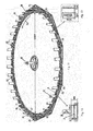
- the circular water tank mainly comprises an inner circular retaining wall 17, an outer circular retaining wall 18, and a circular water tank bottom 19 which three surround together to form the circular water tank structure.
- the sealing head cover is arranged mainly according to the location system.
- a circular water tank inner sealing head cover 20 and a circular water tank outer sealing head cover 21 are respectively arranged on the top of the inner circular retaining wall 17 and the outer circular retaining wall 18.
- only the circular water tank outer sealing head cover 21 are arranged on the top of the outer circular retaining wall 18.
- the inner circular retaining wall 17 may be cancelled.
- the above circular water tank may be replaced directly by a pond.
- it is hard to control the water level.
- the pond when using the pond contain water, it is not convenient to implement a flexible location to the running system, such as a magnetic location cooperated with position by the limiting wheels and so on. As a result, it is difficult for the running system to guide the water in the pond into a honeycomb duct of a hydraulic turbine. Consequently, the axis location way is generally utilized and a mechatronic direct-drive PM generator is equipped when using the pond.
- the circular water tank is a water-suspended circular water tank with an inner cavity structure.
- a filler 22 may be put in the inner cavity of the water-suspended circular water tank, or the inner cavity may be empty.
- the filler 22 may be light and hard polyurethane foam, or be other materials with low cost, small specific gravity, high strength, small water absorption, good compression resistance performance.
- a series of overflow pipes 40 are uniformly provided on the inner circular retaining wall 17 of the circular water tank.
- the overflow pipes 40 may separately or together provided on the outer circular retaining wall 18.
- the liquid in the circular water tank may flow out via such overflow pipes 40, so as to prevent the liquid level too high to affect the location system and the generator system of the wind generator with water float sails.
- a series of water inlet and outlet pipes 41 are uniformly provided on the inner circular retaining wall 17 of the circular water tank. Furthermore, a water inlet and outlet valve 42 and a water inlet and outlet two-way pump 43 are provided on the water inlet and outlet pipes 41.
- the above water inlet and outlet pipes 41 on the inner circular retaining wall 17 may separately or together provided on the outer circular retaining wall 18.
- the water inlet and outlet pipes 41 may separately or together provided on other portions of the circular water tank, such as the circular water tank bottom 19. On condition that this will not impact on the normal operation of the water float running system, the water inlet and outlet pipes 41 may be inserted into the circular water tank from the circular water tank top.
- the water inlet and outlet valve 42 provided on the water inlet and outlet pipes 41 may be switched manually or electric, or with dual mode of manual and electric.
- the water inlet and outlet pipes 41 provided with the water inlet and outlet valve 42 and the water inlet and outlet two-way pump 43 is equipment used to implement a grounding-type braking on the water float running system. It is known from the followed description that the water inlet and outlet pipe 41 is used as a water inlet pipe during watering, and as a water outlet pipe during braking.
- a water channel space 30 is provided between the water float running system and the inner circular retaining wall 17 of the circular water tank, and a water channel space 30 is also provided between the water float running system and the outer circular retaining wall 18 of the circular water tank.
- a water line 37 shown in Figs. 6 and 8 represents the water level of the circular water tank under stationary state.
- the circular water tank is with a water level 38 shown in Fig. 6 in such a motion state where the inner diameter is low and the outer diameter is high.
- the water float running system of the wind generator with water float sails comprises a water float running platform 8 and several ramjet airfoil sails 16.
- the water float running system is floating on the water in the pond or the circular water tank.
- the water float running platform 8 can move in a circle in the horizontal direction by the ramjet airfoil sails 16 capturing wind, which are uniformly arranged on the water float running platform 8.
- the water float running system is an important supporter for the wind generator with water float sails to realize the conversion from wind energy to electric energy, and is a core system of the present invention.
- the water float running platform 8 is a floater and presented as a circular inner cavity structure, which is one part of the water float running platform and used as a base platform carrier to support the ramjet airfoil sails 16 and so on. As shown in Figs. 5 and 7 , in order to cooperate with a hydro-generator equipment, a series of hydro-blades 10 are uniformly arranged on the side of the water float running platform 8.
- a series of waterflow pipes 9 penetrating the water float running platform 8 may be provided on the rear part of each of the hydro-blades 10.
- a filler 22 may be put in the inner cavity of the water float running platform 8, similar to the circular water tank floating on the water.
- each of the ramjet airfoil sails 16 comprises a sail head 3, a sail tail 4, a head gas inlet channel group 1 provided at the sail head 3, an airfoil gas channel group 2 respectively provided at the two airfoils of the sail.
- the head gas inlet channel group 1 comprises a series of gas inlet 7 arranged on the sail head 3.
- the airfoil gas channel group 2 comprises a series of airfoil multipolar gas openings 5, 6 respectively provided at the two airfoils of the sail.
- the above gas inlet 7 and airfoil multipolar gas openings 5, 6 form a jet gas channel inside the ramjet airfoil sails 16, as shown in Fig. 3 .
- the sail with traditional airfoil structure has a good performance of capturing wind, but there is a disadvantage that it can not overcome the frontal drag.
- the ramjet airfoil sail not only has an advantage that it has a large surface to capture wind, but also can reduce the frontal drag effectively and make the composite force of the resistance drive the sail head 3 moving forward so that enhancing the capacity of capturing wind.
- a high pressure region is formed in the face A, and a low pressure region is formed in the face B correspondingly.
- the airfoil multipolar gas openings 6 of the face B presenting as low pressure region may absorb the airflow from the high pressure region of the airfoil multipolar gas openings 5 of the face A, and simultaneously siphon the airflow from the gas inlet 7 of the sail head 3.
- the absorbed and siphoned airflow may eject from the airfoil multipolar gas openings 6 of the face B presenting as low pressure region, so as to improve the composite force driving the ramjet airfoil sails move toward the sail head 3, which may drive the water float running system move in a horizontal circle toward the sail head 3, and vice versa for the action principle of natural wind pressing on the ramjet airfoil sails 16 from the face B.
- the ramjet airfoil sails 16 uniformly arranged on the water float running platform 8 may be applied a composite force to be driven forward at different angle of attack with respect to wind.
- the above ramjet airfoil sails may be selected, or the traditional soft or hard airfoil sail without a ram air jet opening, or the traditional foldable sail with the angle of attack with respect to wind controlled by a computer.
- the sail head 3 is set in front of the sail tail 4 along the counterclockwise direction so as to make the wind generator rotate in the counterclockwise direction 13 shown in Figs. 5 and 11 under the drive of natural wind; and vice versa for the application in the Southern Hemisphere.
- the horizontal rotation of the wind generator is conformed to the "coriolis force" effect to realize rotation under calm air, furthermore to improve the efficiency of the horizontal rotation and to make the wind generator with water float sails start at an extremely low wind speed and run with high efficiency.
- the location system of the wind generator with water float sails is used to effectively locate the rotation of the water float running system floating in the water float tank, so as to improve the stable running reliability of the wind generator with water float sails and reduce the running resistance of the water float running system. Meanwhile, the location system also can reduce the construction cost of the wind generator significantly.
- a magnetic location cooperated with position by limiting wheels and an axis location.
- a location only by limiting wheels or a mechanical rail location and so on.
- the location system comprises one set or several sets of magnetic locating rails combined with a series of limiting wheels.
- the location system comprises one set or several sets of stator magnetic locating rails and one set or several sets of rotator magnetic locating rails arranged on the water float running platform 8 corresponding to the stator magnetic locating rails; wherein, the stator magnetic locating rails are arranged at one position or several positions respectively selected from the following position groups: the inner side of the inner circular retaining wall 17 of the circular water tank, the inner side of the outer circular retaining wall 18 (herein the circular water tank is used a reference, and the respective side of the inner circular retaining wall 17 and the outer circular retaining wall 18, which is surrounding to form a water tank, is defined as the inner side), the lower side of the inner sealing head cover 20, and the lower side of the outer sealing head cover 21.
- the stator magnetic locating rails are arranged at one position or several positions respectively selected from the following position groups: the inner side of the inner circular retaining wall 17 of the circular water tank, the inner side of the outer circular retaining wall 18 (herein the circular water tank is used a reference, and the respective side
- the magnetic location is classified into permanent magnetic location and electromagnetic location.
- the permanent magnetic location is generally classified into permanent magnetic repulsion location, permanent magnetic suction location, permanent magnetic location with combination of repulsion and suction.
- the location system comprises a stator permanent magnetic repulsion locating rail 31 and a rotator permanent magnetic repulsion locating rail 32 corresponding thereto wherein, the stator permanent magnetic repulsion locating rail 31 is arranged on the inner circular retaining wall 17, and the rotator permanent magnetic repulsion locating rail 32 is arranged on the side of the water float running platform 8 which is close to the inner circular retaining wall 17.
- the stator permanent magnetic repulsion locating rail 31 may be respectively or together arranged on the outer circular retaining wall 18. And the rotator permanent magnetic repulsion locating rail 32 may be arranged on the water float running platform 8 and be corresponding to the stator permanent magnetic repulsion locating rail 31.
- stator permanent magnetic repulsion locating rail 31 is arranged on the retaining wall.
- the location system where the stator permanent magnetic repulsion locating rail 31 is arranged on the retaining wall is preferred for the permanent magnetic repulsion locating rail.
- the location system may comprise one set or several sets of stator permanent magnetic repulsion locating rail 31 and one set or several sets of rotator permanent magnetic repulsion locating rail 32 respectively.
- the permanent magnetic materials utilized in the above stator permanent magnetic repulsion locating rail 31 and rotator permanent magnetic repulsion locating rail 32 respectively are correspondingly with the same magnetic pole.
- the location system comprises permanent magnetic suction locating rails 33 respectively and correspondingly arranged on the upper part of the water float running platform 8 and the lower part of the circular water tank inner sealing head cover 20.
- the permanent magnetic suction locating rails 33 may also be respectively and correspondingly arranged on the upper part of the water float running platform 8 and the lower part of the circular water tank outer sealing head cover 21.
- one of the permanent magnetic suction locating rails 33 described above is fixed on the lower part of the circular water tank sealing head cover.
- the location system may comprises one set or several sets of the permanent magnetic suction locating rails 33 which are arranged correspondingly. And the permanent magnetic materials utilized in the permanent magnetic suction locating rails 33 are correspondingly with the opposite magnetic pole.
- both a permanent magnetic repulsion location system and a permanent magnetic suction location system may be provided on the wind generator with water float sails, so as to form a strengthened combination of permanent magnetic force location to implement a more effective location on the water float running system.
- the permanent magnetic force location is a flexible location, it has low locating precise. And such way is generally properly for the location in such a case where the wind generator is running with wind at a normal speed (that is, with wind at such speed, in the permanent magnetic force location, the produced permanent magnetic force can locate the water float running system in the middle of the circular water tank and the water float running system can rotate with respect to a normal position).
- the location system with the limiting wheel comprises a series of upper limiting wheels 26 and lower limiting wheels 27 on one or more position of the inner circular retaining wall 17, the outer circular retaining wall 18 and the water float running platform 8, and/or a series of top limiting wheels 28 on one or more position of the lower side of the inner sealing head cover 20, the lower side of the outer sealing head cover 21 and the upper side of the water float running platform 8.
- Each series of limiting wheels comprise three or more than three limiting wheels which are configured dependent on the mounting sit, quantity and mounting method.
- the lower limiting wheels 27 and even several lines of lower limiting wheels 27 are arranged beneath the upper limiting wheels 26 and opposite to them respectively, so as to increase the positive stop range of transverse drift to the water float running system and ensure the wind generator with water float sails can run safely, reliably and steadily in all kinds of abominable weather conditions. Whilst, it is also can needed to realize safe baking of the wind generator with water float sails that the lower limiting wheels 27 are arranged below the upper limiting wheels 26. During braking, the water level may be decreased with water discharging, and the vertical position of the water float running platform 8 is lowered accordingly. With water discharging, the water float running system is still running and the upper limiting wheels 26 have lost the positive to limit the water float running system. In such a situation, the lower limiting wheels 27 arranged below the upper positive limiting wheels 26 and just opposite to them respectively are needed to implement positive limiting, so as to ensure safe braking of the wind generator with water float sails.
- a series of top limiting wheels 28 are necessary to be arranged on the lower side of the inner sealing head cover 20 and/or on the lower side of the outer sealing head cover 21, so as to implement rigid positive limiting to the horizontal inclination in a c ertain range of the water float running system.
- the ramjet airfoil sails 16 when the ramjet airfoil sails 16 are impacted by normal natural wind, the ramjet airfoil sails 16 will capture wind and consequently drive the water float running system move in a horizontal circle which is floating in the circular water tank. Meanwhile, by the natural wind, the water float running system will also drift horizontally along with the natural wind. However, with the flexible clamping of the magnetic location system, the water float running system will be located in the middle of the circular water tank and rotate steadily with respect to a normal position. At this time, the upper limiting wheels 26, lower limiting wheels 27 and the top limiting wheels 28 are all in an idle state.
- the water float running system rotating in the circular water tank will break the fetter of the permanence magnetic force and drift along with the natural wind, or even be inclined horizontally.
- the water float running system With the flexible clamping of the magnetic location system, the water float running system will soft land on the upper limiting wheels 26, the lower limiting wheels 27 and the top limiting wheels 28 mounting on the lower side of the sealing head cover of the circular water tank, and drive the upper limiting wheels 26, the lower limiting wheels 27 and the top limiting wheels 28 rotation with the water float running system.
- the water float running system will be defined to rotate steadily at a normal position in the circular water tank, so as to realize a rigid location to the horizontal drift and inclination in a certain range of the water float running system.
- an electromagnetic suction compensation location in the electromagnetic location is also applied to strength the location of the water float running system.
- the excess electric power produced by the wind generator with water float sails with wind at an abnormal speed is supplied directly to the electromagnetic induction coil to produce a large electromagnetic force, so as to implement an electromagnetic suction compensation location in real time and based on sections to the horizontal inclination in every direction of the water float running system under the control of an electric controller.
- the electromagnetic suction compensation location system comprises an electromagnetic suction compensation location coil rail 36 arranged at the lower side of the outer sealing head cover 21 or the inner sealing head cover 20 of the circular water tank, a special purpose compensation location steel rail 35 which is arranged on the water float running platform 8 and corresponding to the arranged electromagnetic suction compensation location coil rail 36, and an electric controller.
- the above electromagnetic suction compensation location coil rails 36 may be together or respectively arranged at the lower side of the circular water tank outer sealing head cover 21.
- the special purpose compensation location steel rails 35 are arranged on the water float running platform 8 and just opposite to the electromagnetic suction compensation location coil rails 36 respectively.
- the electromagnetic suction compensation location coil rails 36 are arranged ar the lower side of the circular water tank sealing head cover.
- the electric controller does not identify the signal indicating the inclination of the water float running system.
- the electromagnetic suction compensation location is in an idle state. Only the permanent magnetic force location system can maintain location operation with wind at a normal speed.
- Fig. 6 shows the system of the location maintained by the permanent magnetic repulsion location system with wind at a normal speed.
- Fig. 10 shows the system the location maintained by the permanent magnetic suction location system with wind at a normal speed.
- the water float running system When wind force action exceeds the bearing load of the magnetic force produced by the permanent magnetic force location system, the water float running system may be in a state of acceleration rotation. At this time, the water float running system may not only horizontally drift along with the wind, but also be horizontally inclined at a certain section even with the action of the top limiting wheels 28. At this time, an electric sensor thereupon sends a signal indicating that some section of the water float running system is horizontally inclined. Meanwhile the electromagnetic suction compensation location coil rail 36 controlling such section may produce a strong electromagnetic suction to attract the special purpose compensation location steel rail 35, so as to make the water float running system return to the normal position. As a result, a balance compensation location for the horizontal inclination of the water float running system is accomplished.
- the electromagnetic suction compensation location for the water float running system in real time and based on sections is usually designed for small and medium-sized wind generator with water float sails, and especialy for wind generator with water float sails floating on water, which are with poor running stability.
- the electromagnetic suction compensation location device is not necessary for large-sized wind generator with water float sails with a relative low center of gravity and better running stability.
- one ends of several locating axis connection rods 45 is interlinked to a locating axis 46 provided at the center of a circle of the circular water tank by a locating axis bearing 48 respectively, and the other ends are fixed on the water float running platform 8 uniformly.
- the locating axis 46 is provided with a locating axis protective cover 47.
- the axis location system is presented as radial form taking the locating axis 46 as the center and then locates the water float running system at the normal position which is in the middle of the circular water tank. This is a rigid mechanical locating way with high precision for the wind generator with water float sails. It is also can reduce the construction cost of the wind generator with water float sails to utilize the axis location.
- the axis location is mostly operable to small and medium wind generator with water float sails.
- the locating axis 46, the locating axis connection rods 45 and the locating axis bearing 48 in the axis location system are not required to bear the weight of the water float running system, with the increase of the diameter of the water float running platform, the radius span of the locating axis connection rods 45 may increase correspondingly. This will bring unconquerable technical obstacles for the design of the bearing capability and the stability of a construction of the locating axis 46, the locating axis connection rods 45 and the locating axis bearing 48. Furthermore, a higher request is bring up for the selection of materials. As a result, it may further increase the construction cost.
- the inner circular retaining wall 17 of the circular water tank may be eliminated, and consequently the circular water tank is instead with a pond structure.
- the above locating axis connection rods may be made of rigid materials, or of mooring rope and the like.
- the flexible grounding-type braking system of the wind generator with water float sails comprises a water inlet and outlet valve 42 and an outlet two-way pump 43 both mounted on the water inlet and outlet pipes 41, and the sand stone 39 only used in grounding-type braking which is bedding on a large area of the circular water tank bottom 19.
- the water inlet and outlet valve 42 and an outlet two-way pump 43 mounted on the water inlet and outlet pipes 41 are both switched to drain, consequently the liquid in the circular water tank is discharged gradually, so as to make the water float running system be not acted upon by the buoyancy and stably ground on the sand stone 39 which is bedding on a large area of the circular water tank bottom 19 to stop operation by grounding-type braking.
- the water discharging speed By adjusting and controlling the water discharging speed properly, it is freely to control the grounding-type braking speed of the water float running system. As a result, the braking of the massive water float running system is very safe and reliable.
- the mating generator system of the wind generator with water float sails generally may be a hydro-generator system or a mechatronic direct-drive PM generator system.
- the mating hydro-generator system can transform the water energy produce by the water float running system capturing wind into electric power output.
- the wind generator with water float sails realizes transforming the wind energy into the water energy and meanwhile transforming the water energy into electric power output.
- the mating hydro-generator 23 comprises a generator 11, a hydraulic turbine honeycomb duct 12 and a hydraulic turbine blade 29 coaxial with the generator 11.
- the number and single machine capability of the mating hydro-generator 23 of the hydro-generator system cooperated with the wind generator with water float sails are respectively dependent on the diameter of the water float running platform 8, the area of the ramjet airfoil sails 16, and the output power of the wind generator with water float sails.
- the mating mechatronic generator system can transform the wind energy into electric power output.
- the mating mechatronic generator system comprises a permanent magnetic rail 34 only used in the generator which is mounted on the inner rim of the water float running platform 8, a generator stator coil winding 44 corresponding to the permanent magnetic rail 34 which is mounted on the inner circular retaining wall 17 of the circular water tank.
- the above permanent magnetic rail 34 only used in the generator which is mounted on the inner rim of the water float running platform 8, and the generator stator coil winding 44 corresponding to the permanent magnetic rail 34 which is mounted on the inner circular retaining wall 17 may be correspondingly mounted on the outer rim of the water float running platform 8 and the outer circular retaining wall 18 respectively.
- a strengthened location with a combined-type magnetic location cooperated with limiting wheels is utilized in the wind generator with water float sails mated with a hydro-generator system which is applied in the Northern Hemisphere.
- the running direction is counterclockwise.
- the combined-type magnetic location comprises a permanent magnetic repulsion location rail and an electromagnetic suction compensation rail which two are combined together.
- the permanent magnetic repulsion location rail is consisted of a stator permanent magnetic repulsion location rail 31 arranged on the inner circular retaining wall 17 and the rotator permanent magnetic repulsion location rail 32 corresponding thereto which are arranged on the water float running platform 8, so as to implement location to the wind generator with water float sails with wind at a normal speed.
- the electromagnetic suction compensation rail is consisted of an electromagnetic suction compensation location coil rail 36 mounted at the lower side of the circular water tank outer sealing head cover 21, and a corresponding special purpose compensation location steel rails 35 mounted on the water float running platform 8.
- the limiting wheels comprises upper limiting wheels 26 and lower limiting wheels 27 mounted on the inner circular retaining wall 17, and top limiting wheels 28 mounted at the lower side of the outer sealing head cover 21.
- the electromagnetic suction compensation location combined with the limiting wheel system can implement a strengthened and combined location for the horizontal displacement and horizontal inclination of the water float running system.
- the ramjet airfoil sails 16 uniformly arranged on the water float running platform 8 captures wind so as to drive the water float running system rotate in the counterclockwise direction 13.
- the water float running system can rotate at a relative normal position in the middle of the circular water tank.
- the hydro-blades 10 on the outer rim of the water float running platform 8 the water in the circular water tank also rotate in the counterclockwise direction 13 with the water float running system.
- the rotary water rushes in the direction 14 to the hydraulic turbine honeycomb duct 12 linked to the circular water tank, and then drive the hydraulic turbine blade 29 to rotate, so as to drive the generator 11 to generate synchronously.
- the waterflow rushing to the hydraulic turbine honeycomb duct 12 flows out from the the hydraulic turbine honeycomb duct 12 in the direction 15 and join to the water in the circular water tank to circulate together.
- the wind generator with water floats sail can transform wind energy into water energy, and simultaneously transform water energy into electric power output.
- the permanent magnetic repulsion produced by the permanent magnetic repulsion location system can not limit the water float running system to rotate at a relative normal position in the middle of the circular water tank.
- the water float running system comes up to horizontally drift, by means of the flexible clamping of the permanent magnetic repulsion produced by the permanent magnetic location system, the water float running system will soft land on the upper limiting wheels 26 and the lower limiting wheels 27, and then drive the upper limiting wheels 26 and the lower limiting wheels 27 rotate synchronously.
- the water float running system is rigidly limited to rotate at a relative normal position in the middle of the circular water tank.
- the water float running system When the water float running system comes up to horizontally drift and be horizontally inclined as well, by means of the flexible clamping of the permanent magnetic repulsion, the water float running system will be against the top limiting wheels 28 mounting on the lower side of the sealing head cover. Meanwhile, when the electric controller identifies the horizontal inclination in this section, the electric controller would control the electromagnetic suction compensation location coil rail 36 in such section to produce a strong electromagnetic suction to attract the special purpose compensation location steel rail 35. As a result, the water float running system can return to stably rotate at a normal horizontal position, so as to ensure the wind generator with water float sails can run normally.
- a traditional cross flow hydro-generator may be utilized in the mating hydro-generator 23, of which the hydraulic turbine blade may be fixed-type or rotary-type.
- the arrangement of the hydro-generator may be full cross flow or semi cross flow.
- the energy conversion efficient of such cross flow hydro-generator is about more than 90%, even more than 94%. As such, this kind of low head hydro-generator is particularly suitable for the present implementation solution.
- a mating axis location system, a dependent limiting wheel location system, mechanical rail location system and so on may be provided to locate the water float running system, and to implement the hydraulic turbine generation mode of the wind generator with water float sails.
- the wind generator with water float sails mated with a mechatronic generator system can realize the mechatronic direct-drive generation. It is suitable for the wind generator with water float sails to mate with a mechatronic generator system, especially for the small and medium wind generator with water float sails, with advantages of high conversion efficiency and low construction cost.
- the axis location system is presented as radial form taking the locating axis 46 as the center and then locates the water float running system at the normal position which is in the middle of the circular water tank.
- the ramjet airfoil sail 16 drives the water float running system rotate with the wind.
- the permanent magnetic rail 34 only used in the generator which is mounted on the inner rim of the water float running platform 8 may produce the moving magnetic lines during rotating synchronously with the water float running system.
- the generator stator coil winding 44 fixed on the inner circular retaining wall 17 cuts the moving magnetic lines produced by the permanent magnetic rail 34 to produce electric current. As a result, the mechatronic direct-drive generation is realized.
- an axis location system with high precision is directly utilized in the location, which is facilitated to directly arrange a mating mechatronic direct-drive generation system in the wind generator with water float sails so as to reduce cost substantially.
- a magnetic location cooperated with the limiting wheel system, a dependent limiting wheel system, a mechanical location rail location and so on may be utilized for the water float running system.
- the mechatronic direct-drive generation system requires the water float running system with high precision, and the precision of the magnetic location cooperated with the limiting wheel system is lower than that of the axis location, the magnetic location cooperated with the limiting wheel system is not very suitable for the mechatronic direct-drive generation system.
- the axis location would be generally utilized to implement location to the wind generator with water float sails.
- the wind generator with water float sails applied in the water in the present invention not only can be constructed on land and on the top of the buildings, but also can be constructed floating in the water of the river, lake and ocean.
- there are two kinds of implementation modes which are the water-float-type and the fixed-pile-type wind generator with water float sails respectively.
- Fig. 10 is a cross sectional view of a water-float-type wind generator with water float sails of the wind generator with water float sails according to an embodiment of the present invention.
- the circular water tank is a water-float-type circular water tank which is floating on the water surface 25.
- more than three underwater mooring anchors 24 are provided to hold it.
- the underwater mooring anchors 24 may be movable.
- the water-float-type circular water tank As the water-float-type circular water tank is floating in the water, during the running of the water float running system, the water-float-type circular water tank may pitch up and down under the action of the wave, and the horizontal rotary movement is very unstable with the impact of the wave. However, when the diameter of the water-float-type circular water tank is far larger than the wavelength of the wave, the impact of the pitch produced by the wave on the water-float-type circular water tank will be counteracted. As such, the implementation solution is usually suitable for large and medium or ultra large water-float-type wind generator with water float sails.
- the water float running system of the water-float-type wind generator with water float sails may move in a horizontal circle in a certain direction under the action of the natural wind, and then drive the water in the water-float-type circular water tank rotate synchronously.
- the massive water float running system in rotary movement itself will also produce a strong gyroscopic effect, which will further improve the anti-strong-wave-pitch capability of the water-float-type wind generator with water float sails.
- a mating hydro-generator system is utilized.
- the magnetic location system is a permanent magnetic suction location system comprising permanent magnetic suction locating rails 33 respectively and correspondingly arranged on the upper part of the water float running platform 8 and the lower part of the circular water tank outer sealing head cover 21, so as to implement permanent magnetic suction location to the water float running system with the wind at a normal speed.
- the first set of electromagnetic suction location system is consisted of a special purpose compensation location steel rail 35 arranged on the water float running platform 8 and an electromagnetic suction compensation location coil rail 36 corresponding thereto which is arranged at the lower side of the inner sealing head cover 20.
- the excess electric power produced by the wind generator with water float sails with wind at an abnormal speed is supplied directly to the electromagnetic suction compensation location coil rail 36 to produce a large electromagnetic suction, so as to implement an strong electromagnetic suction compensation location in real time and based on sections to the horizontal inclination in every direction of the water float running system under the control of an electric controller.
- the electromagnetic suction compensation location system can implement a strengthened and combined location for the horizontal displacement and horizontal inclination of the water-float-type wind generator with water float sails in mighty wind and great waves.
- the top limiting wheel 28 provided at the lower side of the outer sealing head cover 21 may be eliminated.
- the electromagnetic suction compensation location coil rail 36 and the special purpose compensation location steel rail 35 may be respectively and correspondingly mounted at the lower side of the circular water tank outer sealing head cover 21 and on the water float running platform 8 to form the second set of strong electromagnetic suction location system.
- the excess electric power produced by the wind generator with water float sails with wind at an abnormal speed is supplied directly to the electromagnetic suction compensation location coil rail 36 to produce a large electromagnetic suction, so as to strengthen the location in basis of time and sections to the horizontal inclination in every direction of the water float running system under the control of an electric controller.
- pile foundations may be constructed directed on the water bottom to upbear the circular water tank, so as to form a fixed wind generator with water float sails.
- a mating hydro-generator system or a mechatronic direct-drive generation system may be utilized as the mating generator system; a magnetic location cooperated withthe limiting wheel system, an axis location system, a dependent positive stop by a limiting wheel system or a mechanical location rail may be utilized as the location.
- the structure design and the generating principle is the same as that of the wind generator with water float sails described above. It is unnecessary to go into details.
- the bottleneck that the unit capacity of the traditional wind generator is limited will be eliminated by technical design and manufacturing process.
- the generator with the capacity of 1000MW can be realized easily, and the unit construction cost is smaller than that of the small and medium wind generator with water float sails.
- a strengthened and combined magnetic location cooperated with the limiting wheel system is utilized for the water float running system with an ultra large diameter.
- 36 ramjet airfoil sails are provided on the water float running platform 8.
- the mating hydro-generating set with an ultra-super power of 1800MW is consisted of 10 mating hydro-generators 23 with unit capacity of 180MW.
- a wind central control tower 50 is provided at the center of the wind generator with water float sails.
- the water float running platform 8 is designed to with a diameter of 1280m, a circumference of 4021 m, a width of 40m and a height of 20m.
- the ramjet airfoil sails 16 is designed to with a height of 136m, a width of 55m, a thickness of 19m, and the space between sails of 56.70m.
- 2/3 of the working displacement of the water float running platform 8 with dimensions set by above data is 2.14 million tons.
- the total weight of the ramjet airfoil sails 16 with dimensions set by above data which is made of reinforced concrete is about 0.61 million tons
- the total weight of the water float running platform 8 with dimensions set by above data and with an inner cavity is about 1.20 million tons.
- the total weight of the water float running system is about 1.81 million tons which is far smaller than the 2/3 of the working displacement of 2.14 million tons.
- the massive water float running system of the wind generator with water float sails is capable of floating in the circular water tank and rotating stably at the 2/3 working waterline.
Landscapes
- Engineering & Computer Science (AREA)
- Life Sciences & Earth Sciences (AREA)
- Sustainable Development (AREA)
- Sustainable Energy (AREA)
- Chemical & Material Sciences (AREA)
- Combustion & Propulsion (AREA)
- Mechanical Engineering (AREA)
- General Engineering & Computer Science (AREA)
- Aviation & Aerospace Engineering (AREA)
- Wind Motors (AREA)
Claims (9)
- Une génératrice éolienne à voiles flottant sur l'eau, comprenant :un bassinou un réservoir d'eau circulaire contenant un liquide;un système flottant sur l'eau qui peut tourner dans le liquide dans le bassinou le réservoir d'eau circulaire sous l'action du vent, le système flottant sur l'eaucomprenantune plate-forme flottant sur l'eau(8), flottant sur le liquide, et plusieurs voiles (16) placées sur la plate-forme flottant sur l'eau;un système de localisation qui peut déterminer la position dusystème flottant sur la surface du liquide et le faire tourner dans un rayon prédéterminé;un système de freinage qui peut arrêter la rotation du système flottant sur l'eau; etun générateur qui peut transformer l'énergie produite par le système flottant-sur l'eau en énergie électrique, caractérisé en ce queun réseau de conduites d'alimentation et d'évacuation d'eau (41) estprévusur le réservoir d'eau circulaire pour verser ou décharger leliquide; etle système de freinagecomprend une vanne d'entrée et de sortie d'eau (42),une pompe à deux voies pour entrée et sortie d'eau (43) prévue sur les conduites d'alimentation et d'évacuation d'eau (41), et un dallage de grès (39) au fond du réservoir d'eau circulaire, servant au système de freinage mis à la terre.
- La génératrice éolienne à voiles flottant sur l'eau selonla revendication 1, dont le réservoir d'eau circulaire est construit sur le sol, sur le toit de l'immeuble ou flottesur l'eau; et
le réservoir d'eau circulaire comprend une paroi de retenue circulaire interne (17), une paroi de retenue circulaire externe (18), et un fond de réservoir d'eau circulaire (19), dans lequel plusieurs conduitesde trop-plein (40) sont prévues sur la paroi de retenue circulaire interne (17) et / ou sur la paroi de retenue circulaire externe (18) à travers laquelle l'excédent de liquide est déchargé dans le réservoir d'eau circulaire. - La génératrice éolienne à voilesflottant sur l'eau selon la revendication 1, dont le réservoir d'eau circulaire comprend en outre un couvercle d'étanchéité intérieuredu réservoir d'eau circulaire (20) disposé sur la partie supérieure de la paroi de retenue circulaire interne (17), et / ou un couvercle d'étanchéité extérieure du réservoir d'eau circulaire (21) disposé sur la partie supérieure de la paroi de retenue circulaire externe(18); le système de localisation comporte un ou plusieurs ensembles de rails de déplacement de force magnétique du stator disposés à un ou plusieurs endroits de la face intérieure de la paroi de retenue circulaire interne (17), la face intérieure de la paroi de retenue circulaire externe (18), la face inférieure du couvercle d'étanchéité intérieure (20) et la face inférieure du couvercle d'étanchéité extérieure (21), et un ou plusieurs ensembles de rails de déplacement de force magnétique du rotateur disposés sur la plate-formeflottant sur l'eau (8) et correspondant aux rails de déplacement de force magnétique du stator.
- La génératrice éolienne à voiles flottant sur l'eau selon la revendication 1 ou 3, dont le système de localisation comprend plusieurs roues de limitation disposées dans un ou plusieurs endroits de la face intérieure de la paroi de retenue circulaire interne(17), la face intérieure de la paroi de retenue circulaire externe (18), la face inférieure du couvercle d'étanchéité intérieure (20), la face inférieure du couvercle d'étanchéité extérieure (21), et la plate-formeflottant sur l'eau (8).
- La génératrice éolienne à voiles flottant sur l'eau selon la revendication 1, le système de localisation comprenantun axe (46) prévu au centre d'un cercle du bassin ou duréservoir d'eau circulaire, un palier d'axe (48) relié à l'axe (46), et plusieurs bielles directrices de l'axe(45) avec une extrémité reliée au palier de l'axe (48) et l'autre extrémité fixée sur la plate-forme flottant sur l'eau (8) de manière uniforme.
- La génératrice éolienne à voilesflottant sur l'eau selon la revendication 1, dont les voiles sont des voiles au profil aérodynamique avecstatoréacteur (16) comprenant un groupe de canaux d'entrée de gaz de la tête (1) installé à la tête d'unevoile (3) de celui-ci et un groupe de canauxde gaz de voilure (2) respectivement au niveau de deux profils de ceux-ci; dont le groupe de canaux d'entrée de gaz de tête (1) comprend plusieurs entrées de gaz (7), et le groupe de canaux de gaz de profil aérodynamique (2) comprend plusieurs bouches de gaz multipolaire de voilures (5, 6) respectivement prévues sur les deux surfaces portantes de la voile; les différentes admissions de gaz (7) et bouches de gaz multipolaire de voilures (5, 6) forment un canal de gaz de réaction à l'intérieur de la voile.
- La génératrice éolienne à voiles flottant sur l'eau selon la revendication 1, dont le système générateur (23) comprend un générateur (11), un système decanaux de turbinehydraulique en nid d'abeilles (12) relié au réservoir d'eau circulaire, et une aube de turbine hydraulique (29) située à l'intérieur du système de canaux de turbine hydraulique en nid d'abeilles (12) et utilisée pour entraîner la génératrice (11); plusieurs hydro-lames (10) sont prévues sur le côté de la plate-forme flottant sur l'eau (8) pour introduire le liquide dans le réservoir d'eau circulaire dans le système de canaux deturbine hydraulique en nid d'abeilles (12).
- La génératrice éolienne à voiles flottant sur l'eau selon la revendication 7, dans laquelle, sur la plate-forme flottant sur l'eau (8), une série de conduitesde débit d'eau (9) estprévue sur la partie arrière de chaque hydro-lame (10), pénétrant dans la faceintérieure et la face extérieure de la plate-forme flottant sur l'eau (8).
- La génératrice éolienne à voiles flottant sur l'eau selon la revendication 1, dont le système générateur comprend un ou plusieurs ensembles de rails magnétiques fixes(34) seulement utilisés dans la génératrice prévue sur la face intérieure de la plate-forme flottant sur l'eau (8) et / ou sur la face extérieure de la plate-forme flottant sur l'eau (8), et un ou plusieurs ensembles de bobines de stator de la génératrice (44) correspondant au rail magnétique fixe (34) qui est prévu sur le réservoir d'eau circulaire.
Applications Claiming Priority (2)
| Application Number | Priority Date | Filing Date | Title |
|---|---|---|---|
| CN2009101106924A CN102042174A (zh) | 2009-10-22 | 2009-10-22 | 水浮风水轮风帆风力发电机 |
| PCT/CN2010/072863 WO2011047546A1 (fr) | 2009-10-22 | 2010-05-18 | Générateur éolien avec une voile flottant sur l'eau |
Publications (3)
| Publication Number | Publication Date |
|---|---|
| EP2492498A1 EP2492498A1 (fr) | 2012-08-29 |
| EP2492498A4 EP2492498A4 (fr) | 2014-05-14 |
| EP2492498B1 true EP2492498B1 (fr) | 2015-07-08 |
Family
ID=43899797
Family Applications (1)
| Application Number | Title | Priority Date | Filing Date |
|---|---|---|---|
| EP10824387.4A Not-in-force EP2492498B1 (fr) | 2009-10-22 | 2010-05-18 | Générateur éolien avec une voile flottant sur l'eau |
Country Status (5)
| Country | Link |
|---|---|
| US (1) | US8742613B2 (fr) |
| EP (1) | EP2492498B1 (fr) |
| CN (2) | CN102042174A (fr) |
| DK (1) | DK2492498T3 (fr) |
| WO (1) | WO2011047546A1 (fr) |
Families Citing this family (15)
| Publication number | Priority date | Publication date | Assignee | Title |
|---|---|---|---|---|
| US8217526B2 (en) * | 2008-11-18 | 2012-07-10 | Andrew J. Devitt | Gearless vertical axis wind turbine with bearing support and power generation at perimeter |
| JP5451687B2 (ja) * | 2011-06-17 | 2014-03-26 | 日立オートモティブシステムズ株式会社 | エンジンの制御装置 |
| CN102562445A (zh) * | 2012-02-24 | 2012-07-11 | 秦明慧 | 一种浮动无轴环型垂直叶片风能机 |
| CN102705171B (zh) * | 2012-07-09 | 2014-02-26 | 赵欣 | 垂直轴双支杆水浮船式特大型风力发电机组结构 |
| CN103019101B (zh) * | 2012-11-26 | 2016-01-13 | 浙江大学 | 一种海上风机吊装控制方法和系统 |
| CN104373289B (zh) * | 2014-05-19 | 2016-01-13 | 秦明慧 | 一种可控输出功率的垂直轴型风能机 |
| US9777709B2 (en) | 2015-01-08 | 2017-10-03 | Hans Dysarsz | Translating foil system for harvesting kinetic energy from wind and flowing water |
| CN104835429B (zh) * | 2015-05-15 | 2017-11-07 | 东莞理工学院 | 一种多功能风力驱动信息展示装置 |
| EP3359808B1 (fr) | 2015-10-30 | 2022-06-01 | Yueli Electric (Jiangsu) Co., Ltd. | Éoliennes entraînées par moyeu de roue |
| CN105508144A (zh) * | 2015-12-12 | 2016-04-20 | 郭策 | 一种小型发电装置 |
| CN106250597B (zh) * | 2016-07-26 | 2019-03-22 | 厦门大学 | 一种完全流向抽吸的三维内转进气道设计方法 |
| RU2665847C1 (ru) * | 2017-05-22 | 2018-09-04 | Вячеслав Антонович Якимчук | Модуль преобразования энергии ветра |
| CN108412687A (zh) | 2017-09-13 | 2018-08-17 | 东莞理工学院 | 一种翼型风帆的自适应升阻力调节方法、风帆及风机 |
| CN109763941A (zh) * | 2019-03-15 | 2019-05-17 | 珠海市静润科技有限公司 | 垂直轴风力发电设备及发电方法 |
| CN116044667A (zh) * | 2022-11-30 | 2023-05-02 | 沈阳工程学院 | 一种水上风力发电设备 |
Family Cites Families (23)
| Publication number | Priority date | Publication date | Assignee | Title |
|---|---|---|---|---|
| GB709201A (en) * | 1950-10-12 | 1954-05-19 | Mining & Land Syndicate Ltd | Improvements in or relating to windmills |
| ES2003473A6 (es) * | 1986-11-06 | 1988-11-01 | Blanco Mateos Eulogio | Un metodo eolico para producir energia |
| DE4232757A1 (de) * | 1992-09-26 | 1994-03-31 | Otto Gerd | Windenergiegroßkonverter |
| ES2154595B1 (es) * | 1999-06-22 | 2001-11-16 | Arcos Manuel Fernandez | Un generador eolico. |
| CN2497076Y (zh) * | 2001-09-30 | 2002-06-26 | 李进 | 垂直轴活动叶片风力发电机 |
| US6952058B2 (en) * | 2003-02-20 | 2005-10-04 | Wecs, Inc. | Wind energy conversion system |
| US9003631B2 (en) * | 2003-10-23 | 2015-04-14 | Shigeyuki Yamamoto | Power generation assemblies and apparatus |
| CN1619142A (zh) * | 2003-11-19 | 2005-05-25 | 申鸿烨 | 一种风力发电机的桨叶 |
| US7220096B2 (en) * | 2004-03-16 | 2007-05-22 | Tocher Angus J | Habitat friendly, multiple impellor, wind energy extraction |
| US7478811B2 (en) * | 2004-08-02 | 2009-01-20 | Garrett Johnson | Wave driven gaming apparatus |
| EP1637733A1 (fr) * | 2004-09-17 | 2006-03-22 | Elsam A/S | Eolienne et méthode de production d'énergie électrique |
| WO2007025387A1 (fr) * | 2005-09-02 | 2007-03-08 | John Christopher Burtch | Dispositif de production de gaz hydrogène utilisant l’action du vent et de la houle |
| US8174135B1 (en) * | 2006-07-10 | 2012-05-08 | Roe Justin C | Marine energy hybrid |
| US20080018115A1 (en) * | 2006-07-20 | 2008-01-24 | Boray Technologies, Inc. | Semi-submersible hydroelectric power plant |
| JP2008163928A (ja) * | 2007-01-05 | 2008-07-17 | Teruo Nishihara | 無風時でも発電可能な風力発電装置 |
| CN101054950B (zh) * | 2007-05-29 | 2012-10-03 | 深圳市风水轮风电科技有限公司 | 磁悬浮钢筋混凝土筑造冲压喷气式翼形风帆风力发电机 |
| CN201078309Y (zh) * | 2007-07-13 | 2008-06-25 | 上海模斯电子设备有限公司 | 一种垂直风力发电机 |
| FR2927958A1 (fr) * | 2008-02-22 | 2009-08-28 | Slawomir Klukowski | Dispositif pour collecter l'energie de la houle. |
| CN101363416B (zh) * | 2008-09-25 | 2010-12-15 | 陆华强 | 帆船式水上风力发电机 |
| US8217526B2 (en) * | 2008-11-18 | 2012-07-10 | Andrew J. Devitt | Gearless vertical axis wind turbine with bearing support and power generation at perimeter |
| CN101463797A (zh) * | 2008-12-23 | 2009-06-24 | 缪江山 | 一种帆式风车 |
| US8698338B2 (en) * | 2010-03-08 | 2014-04-15 | Massachusetts Institute Of Technology | Offshore energy harvesting, storage, and power generation system |
| US8341957B2 (en) * | 2010-04-20 | 2013-01-01 | Joseph Erat S | Portable wave-swash and coastal-wind energy harvester |
-
2009
- 2009-10-22 CN CN2009101106924A patent/CN102042174A/zh active Pending
-
2010
- 2010-05-18 US US13/503,364 patent/US8742613B2/en not_active Expired - Fee Related
- 2010-05-18 WO PCT/CN2010/072863 patent/WO2011047546A1/fr not_active Ceased
- 2010-05-18 EP EP10824387.4A patent/EP2492498B1/fr not_active Not-in-force
- 2010-05-18 DK DK10824387.4T patent/DK2492498T3/da active
- 2010-05-18 CN CN201080047198.9A patent/CN102686875B/zh not_active Expired - Fee Related
Also Published As
| Publication number | Publication date |
|---|---|
| HK1175827A1 (en) | 2013-07-12 |
| US8742613B2 (en) | 2014-06-03 |
| CN102042174A (zh) | 2011-05-04 |
| WO2011047546A1 (fr) | 2011-04-28 |
| CN102686875A (zh) | 2012-09-19 |
| EP2492498A4 (fr) | 2014-05-14 |
| CN102686875B (zh) | 2015-01-14 |
| EP2492498A1 (fr) | 2012-08-29 |
| US20120217755A1 (en) | 2012-08-30 |
| DK2492498T3 (en) | 2015-07-20 |
Similar Documents
| Publication | Publication Date | Title |
|---|---|---|
| EP2492498B1 (fr) | Générateur éolien avec une voile flottant sur l'eau | |
| US8152441B2 (en) | Submersible waterwheel with hinged rotor blades and spring-loaded water seals | |
| EP2496836B1 (fr) | Turbine éolienne flottante | |
| JP2014526642A (ja) | 改良型水ロータ用のシステム及び方法 | |
| CN103119288B (zh) | 从流动的液体中提取能源的设备 | |
| CN104787280A (zh) | 双轴叶桨轮气流体液流体集力升力推力器 | |
| WO2022236677A1 (fr) | Structure d'aide à la flottaison et d'enfoncement auxiliaire d'un ensemble d'énergie éolienne en mer ayant une fondation par godet-pompe | |
| CN214998008U (zh) | 一种可移动式水平轴潮流能水轮机增能装置 | |
| CN1773104A (zh) | 气室斜靠岸式单向稳定气流波能发电装置 | |
| US11946457B1 (en) | High-mass hydro rotor for hydroelectric power generation | |
| CN101725454A (zh) | 陀螺机潮汐发电装置 | |
| CN216472464U (zh) | 一种多功能两栖式河湖治理浮岛装置 | |
| CN105041573B (zh) | 一种垂直轴风力/水力发电装置 | |
| CN210829578U (zh) | 一种横卧式水轮系统 | |
| CN102155346B (zh) | 扩径引流型流体聚流集能装置和方法 | |
| CN101929413B (zh) | 随水位自动调节的水轮机及应用 | |
| CN113006012A (zh) | 漂浮式涡轮水力发电小型基站 | |
| HK1175827B (zh) | 水浮风帆风力发电机 | |
| CN109653940A (zh) | 基于喷射泵的静水上升循环发电系统 | |
| CN216304594U (zh) | 水下涵道式水力发电系统 | |
| US20250283448A1 (en) | High-mass hydro rotor for hydroelectric power generation | |
| US12305609B2 (en) | High-mass hydro rotor for hydroelectric power generation | |
| CN219119366U (zh) | 一种江河水力发电设备 | |
| CN201650565U (zh) | 双轮半潜银屏式海流发电装置 | |
| CN106150838B (zh) | 一种海流能高效捕获与利用装置 |
Legal Events
| Date | Code | Title | Description |
|---|---|---|---|
| PUAI | Public reference made under article 153(3) epc to a published international application that has entered the european phase |
Free format text: ORIGINAL CODE: 0009012 |
|
| 17P | Request for examination filed |
Effective date: 20120521 |
|
| AK | Designated contracting states |
Kind code of ref document: A1 Designated state(s): AL AT BE BG CH CY CZ DE DK EE ES FI FR GB GR HR HU IE IS IT LI LT LU LV MC MK MT NL NO PL PT RO SE SI SK SM TR |
|
| DAX | Request for extension of the european patent (deleted) | ||
| A4 | Supplementary search report drawn up and despatched |
Effective date: 20140415 |
|
| RIC1 | Information provided on ipc code assigned before grant |
Ipc: F03D 5/00 20060101AFI20140409BHEP Ipc: F03D 3/06 20060101ALI20140409BHEP |
|
| GRAP | Despatch of communication of intention to grant a patent |
Free format text: ORIGINAL CODE: EPIDOSNIGR1 |
|
| INTG | Intention to grant announced |
Effective date: 20141212 |
|
| RIC1 | Information provided on ipc code assigned before grant |
Ipc: F03D 5/00 20060101AFI20141202BHEP Ipc: F03D 3/06 20060101ALI20141202BHEP |
|
| GRAS | Grant fee paid |
Free format text: ORIGINAL CODE: EPIDOSNIGR3 |
|
| GRAA | (expected) grant |
Free format text: ORIGINAL CODE: 0009210 |
|
| AK | Designated contracting states |
Kind code of ref document: B1 Designated state(s): AL AT BE BG CH CY CZ DE DK EE ES FI FR GB GR HR HU IE IS IT LI LT LU LV MC MK MT NL NO PL PT RO SE SI SK SM TR |
|
| REG | Reference to a national code |
Ref country code: GB Ref legal event code: FG4D |
|
| REG | Reference to a national code |
Ref country code: AT Ref legal event code: REF Ref document number: 735623 Country of ref document: AT Kind code of ref document: T Effective date: 20150715 Ref country code: CH Ref legal event code: EP |
|
| REG | Reference to a national code |
Ref country code: DK Ref legal event code: T3 Effective date: 20150714 |
|
| REG | Reference to a national code |
Ref country code: IE Ref legal event code: FG4D |
|
| REG | Reference to a national code |
Ref country code: DE Ref legal event code: R096 Ref document number: 602010025815 Country of ref document: DE |
|
| REG | Reference to a national code |
Ref country code: NL Ref legal event code: T3 |
|
| REG | Reference to a national code |
Ref country code: AT Ref legal event code: MK05 Ref document number: 735623 Country of ref document: AT Kind code of ref document: T Effective date: 20150708 |
|
| REG | Reference to a national code |
Ref country code: LT Ref legal event code: MG4D |
|
| PG25 | Lapsed in a contracting state [announced via postgrant information from national office to epo] |
Ref country code: GR Free format text: LAPSE BECAUSE OF FAILURE TO SUBMIT A TRANSLATION OF THE DESCRIPTION OR TO PAY THE FEE WITHIN THE PRESCRIBED TIME-LIMIT Effective date: 20151009 Ref country code: FI Free format text: LAPSE BECAUSE OF FAILURE TO SUBMIT A TRANSLATION OF THE DESCRIPTION OR TO PAY THE FEE WITHIN THE PRESCRIBED TIME-LIMIT Effective date: 20150708 Ref country code: NO Free format text: LAPSE BECAUSE OF FAILURE TO SUBMIT A TRANSLATION OF THE DESCRIPTION OR TO PAY THE FEE WITHIN THE PRESCRIBED TIME-LIMIT Effective date: 20151008 Ref country code: LT Free format text: LAPSE BECAUSE OF FAILURE TO SUBMIT A TRANSLATION OF THE DESCRIPTION OR TO PAY THE FEE WITHIN THE PRESCRIBED TIME-LIMIT Effective date: 20150708 Ref country code: LV Free format text: LAPSE BECAUSE OF FAILURE TO SUBMIT A TRANSLATION OF THE DESCRIPTION OR TO PAY THE FEE WITHIN THE PRESCRIBED TIME-LIMIT Effective date: 20150708 |
|
| PG25 | Lapsed in a contracting state [announced via postgrant information from national office to epo] |
Ref country code: ES Free format text: LAPSE BECAUSE OF FAILURE TO SUBMIT A TRANSLATION OF THE DESCRIPTION OR TO PAY THE FEE WITHIN THE PRESCRIBED TIME-LIMIT Effective date: 20150708 Ref country code: AT Free format text: LAPSE BECAUSE OF FAILURE TO SUBMIT A TRANSLATION OF THE DESCRIPTION OR TO PAY THE FEE WITHIN THE PRESCRIBED TIME-LIMIT Effective date: 20150708 Ref country code: PT Free format text: LAPSE BECAUSE OF FAILURE TO SUBMIT A TRANSLATION OF THE DESCRIPTION OR TO PAY THE FEE WITHIN THE PRESCRIBED TIME-LIMIT Effective date: 20151109 Ref country code: PL Free format text: LAPSE BECAUSE OF FAILURE TO SUBMIT A TRANSLATION OF THE DESCRIPTION OR TO PAY THE FEE WITHIN THE PRESCRIBED TIME-LIMIT Effective date: 20150708 Ref country code: SE Free format text: LAPSE BECAUSE OF FAILURE TO SUBMIT A TRANSLATION OF THE DESCRIPTION OR TO PAY THE FEE WITHIN THE PRESCRIBED TIME-LIMIT Effective date: 20150708 Ref country code: HR Free format text: LAPSE BECAUSE OF FAILURE TO SUBMIT A TRANSLATION OF THE DESCRIPTION OR TO PAY THE FEE WITHIN THE PRESCRIBED TIME-LIMIT Effective date: 20150708 Ref country code: IS Free format text: LAPSE BECAUSE OF FAILURE TO SUBMIT A TRANSLATION OF THE DESCRIPTION OR TO PAY THE FEE WITHIN THE PRESCRIBED TIME-LIMIT Effective date: 20151108 |
|
| REG | Reference to a national code |
Ref country code: DE Ref legal event code: R097 Ref document number: 602010025815 Country of ref document: DE |
|
| PG25 | Lapsed in a contracting state [announced via postgrant information from national office to epo] |
Ref country code: CZ Free format text: LAPSE BECAUSE OF FAILURE TO SUBMIT A TRANSLATION OF THE DESCRIPTION OR TO PAY THE FEE WITHIN THE PRESCRIBED TIME-LIMIT Effective date: 20150708 Ref country code: EE Free format text: LAPSE BECAUSE OF FAILURE TO SUBMIT A TRANSLATION OF THE DESCRIPTION OR TO PAY THE FEE WITHIN THE PRESCRIBED TIME-LIMIT Effective date: 20150708 Ref country code: SK Free format text: LAPSE BECAUSE OF FAILURE TO SUBMIT A TRANSLATION OF THE DESCRIPTION OR TO PAY THE FEE WITHIN THE PRESCRIBED TIME-LIMIT Effective date: 20150708 Ref country code: IT Free format text: LAPSE BECAUSE OF FAILURE TO SUBMIT A TRANSLATION OF THE DESCRIPTION OR TO PAY THE FEE WITHIN THE PRESCRIBED TIME-LIMIT Effective date: 20150708 |
|
| PLBE | No opposition filed within time limit |
Free format text: ORIGINAL CODE: 0009261 |
|
| STAA | Information on the status of an ep patent application or granted ep patent |
Free format text: STATUS: NO OPPOSITION FILED WITHIN TIME LIMIT |
|
| REG | Reference to a national code |
Ref country code: FR Ref legal event code: PLFP Year of fee payment: 7 |
|
| PG25 | Lapsed in a contracting state [announced via postgrant information from national office to epo] |
Ref country code: RO Free format text: LAPSE BECAUSE OF FAILURE TO SUBMIT A TRANSLATION OF THE DESCRIPTION OR TO PAY THE FEE WITHIN THE PRESCRIBED TIME-LIMIT Effective date: 20150708 |
|
| 26N | No opposition filed |
Effective date: 20160411 |
|
| PG25 | Lapsed in a contracting state [announced via postgrant information from national office to epo] |
Ref country code: SI Free format text: LAPSE BECAUSE OF FAILURE TO SUBMIT A TRANSLATION OF THE DESCRIPTION OR TO PAY THE FEE WITHIN THE PRESCRIBED TIME-LIMIT Effective date: 20150708 Ref country code: BE Free format text: LAPSE BECAUSE OF NON-PAYMENT OF DUE FEES Effective date: 20160531 |
|
| PG25 | Lapsed in a contracting state [announced via postgrant information from national office to epo] |
Ref country code: LU Free format text: LAPSE BECAUSE OF FAILURE TO SUBMIT A TRANSLATION OF THE DESCRIPTION OR TO PAY THE FEE WITHIN THE PRESCRIBED TIME-LIMIT Effective date: 20160518 Ref country code: BE Free format text: LAPSE BECAUSE OF FAILURE TO SUBMIT A TRANSLATION OF THE DESCRIPTION OR TO PAY THE FEE WITHIN THE PRESCRIBED TIME-LIMIT Effective date: 20150708 |
|
| REG | Reference to a national code |
Ref country code: CH Ref legal event code: PL |
|
| PG25 | Lapsed in a contracting state [announced via postgrant information from national office to epo] |
Ref country code: LI Free format text: LAPSE BECAUSE OF NON-PAYMENT OF DUE FEES Effective date: 20160531 Ref country code: CH Free format text: LAPSE BECAUSE OF NON-PAYMENT OF DUE FEES Effective date: 20160531 |
|
| REG | Reference to a national code |
Ref country code: IE Ref legal event code: MM4A |
|
| REG | Reference to a national code |
Ref country code: FR Ref legal event code: PLFP Year of fee payment: 8 |
|
| PG25 | Lapsed in a contracting state [announced via postgrant information from national office to epo] |
Ref country code: IE Free format text: LAPSE BECAUSE OF NON-PAYMENT OF DUE FEES Effective date: 20160518 |
|
| REG | Reference to a national code |
Ref country code: FR Ref legal event code: PLFP Year of fee payment: 9 |
|
| PG25 | Lapsed in a contracting state [announced via postgrant information from national office to epo] |
Ref country code: HU Free format text: LAPSE BECAUSE OF FAILURE TO SUBMIT A TRANSLATION OF THE DESCRIPTION OR TO PAY THE FEE WITHIN THE PRESCRIBED TIME-LIMIT; INVALID AB INITIO Effective date: 20100518 Ref country code: SM Free format text: LAPSE BECAUSE OF FAILURE TO SUBMIT A TRANSLATION OF THE DESCRIPTION OR TO PAY THE FEE WITHIN THE PRESCRIBED TIME-LIMIT Effective date: 20150708 Ref country code: CY Free format text: LAPSE BECAUSE OF FAILURE TO SUBMIT A TRANSLATION OF THE DESCRIPTION OR TO PAY THE FEE WITHIN THE PRESCRIBED TIME-LIMIT Effective date: 20150708 |
|
| PG25 | Lapsed in a contracting state [announced via postgrant information from national office to epo] |
Ref country code: MC Free format text: LAPSE BECAUSE OF FAILURE TO SUBMIT A TRANSLATION OF THE DESCRIPTION OR TO PAY THE FEE WITHIN THE PRESCRIBED TIME-LIMIT Effective date: 20150708 Ref country code: MK Free format text: LAPSE BECAUSE OF FAILURE TO SUBMIT A TRANSLATION OF THE DESCRIPTION OR TO PAY THE FEE WITHIN THE PRESCRIBED TIME-LIMIT Effective date: 20150708 Ref country code: TR Free format text: LAPSE BECAUSE OF FAILURE TO SUBMIT A TRANSLATION OF THE DESCRIPTION OR TO PAY THE FEE WITHIN THE PRESCRIBED TIME-LIMIT Effective date: 20150708 Ref country code: MT Free format text: LAPSE BECAUSE OF NON-PAYMENT OF DUE FEES Effective date: 20160531 |
|
| PG25 | Lapsed in a contracting state [announced via postgrant information from national office to epo] |
Ref country code: BG Free format text: LAPSE BECAUSE OF FAILURE TO SUBMIT A TRANSLATION OF THE DESCRIPTION OR TO PAY THE FEE WITHIN THE PRESCRIBED TIME-LIMIT Effective date: 20150708 |
|
| PGFP | Annual fee paid to national office [announced via postgrant information from national office to epo] |
Ref country code: DK Payment date: 20180518 Year of fee payment: 9 Ref country code: DE Payment date: 20180522 Year of fee payment: 9 |
|
| PGFP | Annual fee paid to national office [announced via postgrant information from national office to epo] |
Ref country code: NL Payment date: 20180518 Year of fee payment: 9 Ref country code: FR Payment date: 20180522 Year of fee payment: 9 |
|
| PG25 | Lapsed in a contracting state [announced via postgrant information from national office to epo] |
Ref country code: AL Free format text: LAPSE BECAUSE OF FAILURE TO SUBMIT A TRANSLATION OF THE DESCRIPTION OR TO PAY THE FEE WITHIN THE PRESCRIBED TIME-LIMIT Effective date: 20150708 |
|
| PGFP | Annual fee paid to national office [announced via postgrant information from national office to epo] |
Ref country code: GB Payment date: 20180518 Year of fee payment: 9 |
|
| REG | Reference to a national code |
Ref country code: DE Ref legal event code: R119 Ref document number: 602010025815 Country of ref document: DE |
|
| REG | Reference to a national code |
Ref country code: DK Ref legal event code: EBP Effective date: 20190531 |
|
| REG | Reference to a national code |
Ref country code: NL Ref legal event code: MM Effective date: 20190601 |
|
| GBPC | Gb: european patent ceased through non-payment of renewal fee |
Effective date: 20190518 |
|
| PG25 | Lapsed in a contracting state [announced via postgrant information from national office to epo] |
Ref country code: GB Free format text: LAPSE BECAUSE OF NON-PAYMENT OF DUE FEES Effective date: 20190518 Ref country code: NL Free format text: LAPSE BECAUSE OF NON-PAYMENT OF DUE FEES Effective date: 20190601 Ref country code: DK Free format text: LAPSE BECAUSE OF NON-PAYMENT OF DUE FEES Effective date: 20190531 Ref country code: DE Free format text: LAPSE BECAUSE OF NON-PAYMENT OF DUE FEES Effective date: 20191203 |
|
| PG25 | Lapsed in a contracting state [announced via postgrant information from national office to epo] |
Ref country code: FR Free format text: LAPSE BECAUSE OF NON-PAYMENT OF DUE FEES Effective date: 20190531 |