EP2492463B1 - Dispositif d'épuration d'échappement de moteur à combustion interne - Google Patents
Dispositif d'épuration d'échappement de moteur à combustion interne Download PDFInfo
- Publication number
- EP2492463B1 EP2492463B1 EP09850536.5A EP09850536A EP2492463B1 EP 2492463 B1 EP2492463 B1 EP 2492463B1 EP 09850536 A EP09850536 A EP 09850536A EP 2492463 B1 EP2492463 B1 EP 2492463B1
- Authority
- EP
- European Patent Office
- Prior art keywords
- temperature
- fuel
- exhaust
- burning
- ignition means
- Prior art date
- Legal status (The legal status is an assumption and is not a legal conclusion. Google has not performed a legal analysis and makes no representation as to the accuracy of the status listed.)
- Not-in-force
Links
Images

Classifications
-
- F—MECHANICAL ENGINEERING; LIGHTING; HEATING; WEAPONS; BLASTING
- F01—MACHINES OR ENGINES IN GENERAL; ENGINE PLANTS IN GENERAL; STEAM ENGINES
- F01N—GAS-FLOW SILENCERS OR EXHAUST APPARATUS FOR MACHINES OR ENGINES IN GENERAL; GAS-FLOW SILENCERS OR EXHAUST APPARATUS FOR INTERNAL-COMBUSTION ENGINES
- F01N3/00—Exhaust or silencing apparatus having means for purifying, rendering innocuous, or otherwise treating exhaust
- F01N3/08—Exhaust or silencing apparatus having means for purifying, rendering innocuous, or otherwise treating exhaust for rendering innocuous
- F01N3/10—Exhaust or silencing apparatus having means for purifying, rendering innocuous, or otherwise treating exhaust for rendering innocuous by thermal or catalytic conversion of noxious components of exhaust
- F01N3/24—Exhaust or silencing apparatus having means for purifying, rendering innocuous, or otherwise treating exhaust for rendering innocuous by thermal or catalytic conversion of noxious components of exhaust characterised by constructional aspects of converting apparatus
- F01N3/36—Arrangements for supply of additional fuel
-
- F—MECHANICAL ENGINEERING; LIGHTING; HEATING; WEAPONS; BLASTING
- F01—MACHINES OR ENGINES IN GENERAL; ENGINE PLANTS IN GENERAL; STEAM ENGINES
- F01N—GAS-FLOW SILENCERS OR EXHAUST APPARATUS FOR MACHINES OR ENGINES IN GENERAL; GAS-FLOW SILENCERS OR EXHAUST APPARATUS FOR INTERNAL-COMBUSTION ENGINES
- F01N9/00—Electrical control of exhaust gas treating apparatus
-
- F—MECHANICAL ENGINEERING; LIGHTING; HEATING; WEAPONS; BLASTING
- F01—MACHINES OR ENGINES IN GENERAL; ENGINE PLANTS IN GENERAL; STEAM ENGINES
- F01N—GAS-FLOW SILENCERS OR EXHAUST APPARATUS FOR MACHINES OR ENGINES IN GENERAL; GAS-FLOW SILENCERS OR EXHAUST APPARATUS FOR INTERNAL-COMBUSTION ENGINES
- F01N2240/00—Combination or association of two or more different exhaust treating devices, or of at least one such device with an auxiliary device, not covered by indexing codes F01N2230/00 or F01N2250/00, one of the devices being
- F01N2240/14—Combination or association of two or more different exhaust treating devices, or of at least one such device with an auxiliary device, not covered by indexing codes F01N2230/00 or F01N2250/00, one of the devices being a fuel burner
-
- F—MECHANICAL ENGINEERING; LIGHTING; HEATING; WEAPONS; BLASTING
- F01—MACHINES OR ENGINES IN GENERAL; ENGINE PLANTS IN GENERAL; STEAM ENGINES
- F01N—GAS-FLOW SILENCERS OR EXHAUST APPARATUS FOR MACHINES OR ENGINES IN GENERAL; GAS-FLOW SILENCERS OR EXHAUST APPARATUS FOR INTERNAL-COMBUSTION ENGINES
- F01N2550/00—Monitoring or diagnosing the deterioration of exhaust systems
-
- F—MECHANICAL ENGINEERING; LIGHTING; HEATING; WEAPONS; BLASTING
- F01—MACHINES OR ENGINES IN GENERAL; ENGINE PLANTS IN GENERAL; STEAM ENGINES
- F01N—GAS-FLOW SILENCERS OR EXHAUST APPARATUS FOR MACHINES OR ENGINES IN GENERAL; GAS-FLOW SILENCERS OR EXHAUST APPARATUS FOR INTERNAL-COMBUSTION ENGINES
- F01N2610/00—Adding substances to exhaust gases
- F01N2610/03—Adding substances to exhaust gases the substance being hydrocarbons, e.g. engine fuel
-
- Y—GENERAL TAGGING OF NEW TECHNOLOGICAL DEVELOPMENTS; GENERAL TAGGING OF CROSS-SECTIONAL TECHNOLOGIES SPANNING OVER SEVERAL SECTIONS OF THE IPC; TECHNICAL SUBJECTS COVERED BY FORMER USPC CROSS-REFERENCE ART COLLECTIONS [XRACs] AND DIGESTS
- Y02—TECHNOLOGIES OR APPLICATIONS FOR MITIGATION OR ADAPTATION AGAINST CLIMATE CHANGE
- Y02T—CLIMATE CHANGE MITIGATION TECHNOLOGIES RELATED TO TRANSPORTATION
- Y02T10/00—Road transport of goods or passengers
- Y02T10/10—Internal combustion engine [ICE] based vehicles
- Y02T10/12—Improving ICE efficiencies
-
- Y—GENERAL TAGGING OF NEW TECHNOLOGICAL DEVELOPMENTS; GENERAL TAGGING OF CROSS-SECTIONAL TECHNOLOGIES SPANNING OVER SEVERAL SECTIONS OF THE IPC; TECHNICAL SUBJECTS COVERED BY FORMER USPC CROSS-REFERENCE ART COLLECTIONS [XRACs] AND DIGESTS
- Y02—TECHNOLOGIES OR APPLICATIONS FOR MITIGATION OR ADAPTATION AGAINST CLIMATE CHANGE
- Y02T—CLIMATE CHANGE MITIGATION TECHNOLOGIES RELATED TO TRANSPORTATION
- Y02T10/00—Road transport of goods or passengers
- Y02T10/10—Internal combustion engine [ICE] based vehicles
- Y02T10/40—Engine management systems
Definitions
- the present invention relates to an exhaust purifying apparatus having a function supplying fuel into an exhaust passage in an internal combustion engine.
- a catalyst provided in an exhaust passage in an internal combustion engine has an active temperature range appropriate for purification of hazardous components. When a temperature of the catalyst is out of this active temperature range, the purification capability is remarkably degraded.
- an addition valve for injecting fuel and ignition means for igniting the injected fuel are provided upstream of the catalyst in the exhaust passage.
- the fuel supplied from the addition valve is ignited by the ignition means to increase the temperature of the catalyst.
- the present invention has an object of suppressing degradation of ignition means due to combustion of attached foreign objects. This object is solved by the exhaust purifying apparatus for an internal combustion engine according to claim 1.
- an exhaust purifying apparatus for an internal combustion engine comprises:
- the exhaust purifying apparatus further comprises:
- Said controller executes the burning of the fuel under a predetermined condition, which condition is at least one of: that a suppression time has elapsed following the removal by the removal operation, said suppression time being predetermined so that, even if burning of the fuel by the temperature increasing means is executed, the temperature of the ignition means would be lower than an upper limit temperature which would not degrade the ignition means; and that a temperature of the ignition means is lower than an upper limit temperature, said upper limit temperature being predetermined so that, even if burning of the fuel by the temperature increasing means is executed when the temperature is lower than said upper limit temperature, the temperature of the ignition means would be lower than an upper limit temperature which would not degrade the ignition means.
- the fuel supplying means supplies the fuel into the exhaust passage in the internal combustion engine
- the ignition means burns the fuel supplied from the fuel supplying means.
- the temperature increasing means increases the temperature of the exhaust gas flowing in the exhaust passage by igniting the fuel supplied from the fuel supplying means by the ignition means.
- the removal means in a case where unburned components of the exhaust gas are deposited in the ignition means, burns the deposited unburned components for removal prior to the execution of the temperature increase by the temperature increasing means. The deposited unburned components are removed by the removal means and thereafter, the temperature increase is made by the temperature increasing means. Therefore, an excessive increase of the temperature of the ignition means can be suppressed, thus suppressing degradation of the ignition means.
- the apparatus in the present invention may further comprise:
- the apparatus in the present invention may further comprise:
- an excessive temperature increase can be suppressed to suitably suppress the degradation of the ignition means.
- an exhaust purifying apparatus for an internal combustion engine has an engine 1, an intake pipe 2 and an exhaust pipe 3.
- the engine 1 is a diesel internal combustion engine, but may be of the other type of internal combustion engine.
- a throttle valve 4 and a surge tank 5 are arranged in the intake pipe 2.
- the throttle valve 4 is driven by a throttle actuator 7.
- An injector 6 for driving is provided and is directed toward a combustion chamber in the engine 1.
- the exhaust pipe 3 is connected to the engine 1 at the upstream side as the left side in Fig. 1 and is connected to a muffler (not shown) at the downstream side as the right side in the figure.
- a catalyst 11 is provided in the exhaust pipe 3.
- the catalyst 11 is composed of, for example, an oxidation catalyst, a three-way catalyst or a NOx catalyst and the base material is made of cordierite or metal.
- An injector 12 for catalyst heating is installed in the exhaust pipe 3 upstream of the catalyst 11 for an injection opening thereof to be exposed to an inside of the exhaust pipe 3.
- Fuel in a fuel tank 13 is supplied via a pump 14 to the injector 12. It should be noted that, for accelerating the combustion, a pipe line, a control valve and a compressor for supplying air for combustion into the exhaust pipe 3 from an outside may be provided.
- a glow plug 15 is provided in the exhaust pipe 3 downstream of the injector 12.
- the glow plug 15 is installed in a position where fuel added from the injector 12 makes contact with the glow plug 15.
- the glow plug 15 has a tip end projecting into the exhaust passage.
- a direct-current power source 16 and a voltage boosting circuit 17 for supplying power to the glow plug 15 are connected to the glow plug 15.
- a ceramic heater may be used as the ignition means or the heating apparatus instead of the glow plug.
- An exhaust temperature sensor 18 is installed in the exhaust pipe 3 upstream of the catalyst 11.
- the exhaust temperature sensor 18 has a thermistor of which a resistance value changes depending on a temperature. A change of the exhaust temperature can be detected by a change in the resistance value of the thermistor.
- An air-fuel ratio sensor 19 is provided in the exhaust pipe 3 downstream of the catalyst 11.
- the air-fuel ratio sensor 19 has a sheet-shaped solid electrolyte element made of an oxygen ion conductive material (for example, zirconia) and a pair of electrodes sandwiching the solid electrolyte element and generates output in proportion to an oxygen density in the exhaust gas.
- the air-fuel ratio sensor 19 is of a so-called laminate type in which the solid electrolyte is directly heated by a heater incorporated therein, but may be of a cup type in which the solid electrolyte is indirectly heated through an atmospheric layer.
- the exhaust pipe 3 downstream of the catalyst 11 is connected to the intake pipe 2 downstream of the surge tank 5 to form an EGR (exhaust gas recirculation) passage 20.
- An intercooler 21 for cooling an exhaust gas and an EGR control valve 22 for controlling a flow amount of the exhaust gas are arranged in the EGR passage 20.
- the ECU 30 is a well-known one-chip microprocessor and is equipped with a CPU, a ROM, a RAM, an involatile memory apparatus, an input/output interface, an A/D converter and a D/A converter.
- Various types of sensors are electrically connected to the input/output interface in the ECU 30 for detecting a state of a vehicle including an engine operating state and an engine operating input state, and signals of the sensors are inputted thereto. Examples of such various types of sensors include the exhaust temperature sensor 18 and the air-fuel ratio sensor 19 described above, further an air flow meter, a throttle opening sensor, a crank angle sensor, and an accelerator pedal sensor.
- the injectors 6 and 12, the throttle actuator 7, the pump 14, the boosting circuit 17 and the EGR control valve 22 are electrically connected to the output interface of the ECU 30, which outputs control signals.
- the ECU 30 calculates a fuel supply indication quantity based upon parameters showing a state of a vehicle including the air flow meter, the throttle opening sensor, the crank angle sensor, and the accelerator pedal sensor, particularly an operating state of the engine, and outputs a control signal for opening the injectors 6 and 12 by a time corresponding to the indication quantity. Fuel of a quantity corresponding to the fuel supply indication quantity is supplied from the injectors 6 and 12 in response to the control signal.
- Various kinds of programs, reference values and initial values are stored in the ROM of the ECU 30.
- the reference values and the initial values include a suppression time tc and an upper limit temperature Ta used in the process to be described later.
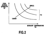
- a fuel supply time map produced in advance (refer to Fig. 2 ) is stored in the ROM of the ECU 30.
- An exhaust temperature Te, a fuel supply quantity Qf, and a fuel supply time ts are associated with each other, which are stored in the fuel supply time map.
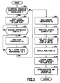
- the ECU 30 executes the following catalyst heating process immediately after a starting-up state of an engine from a cold stop state thereof.
- the ECU 30 first determines whether or not a predetermined removal operation execution condition is established (S10).
- the removal operation execution condition can be defined as the event that a predetermined time, for which HC or PM is possibly deposited to some extent, elapses (or a vehicle travels by a predetermined travel distance) from a point where the glow plug 15 is finally power-supplied and heated.
- the removal operation may be performed in an arbitrary timing when the fuel addition is not made from the injector 12. In a case where the execution condition is not established, step S20 to step S50 are skipped.
- the ECU 30 starts power-supply (that is, heating) to the glow plug 15 (S20).
- This power-supply continues to be performed over a predetermined suppression time tc (S30), and fuel is not supplied from the injector 12 during that period.
- the suppression time tc is set to a time large enough for the unburned components deposited in the heating portion of the glow plug 15 to burn and removed.
- the heating by the glow plug 15 continues to be performed during the period of the suppression time tc, but after the deposited unburned components are burned, since the glow plug 15 is cooled by the exhaust flow, a temperature of the glow plug 15 is lowered.
- a value of the suppression time tc may be a fixed value or may be set dynamically. In a case where the suppression time tc is set dynamically, the value may be set based upon a parameter relating to an amount of the deposited unburned components (for example, a cumulative travel time, a cumulative travel distance or a cumulative fuel addition quantity after the previous removal process) and/or a parameter relating to a combustion velocity of the deposited unburned components (for example, an engine water temperature or exhaust temperature).
- a parameter relating to an amount of the deposited unburned components for example, a cumulative travel time, a cumulative travel distance or a cumulative fuel addition quantity after the previous removal process
- a parameter relating to a combustion velocity of the deposited unburned components for example, an engine water temperature or exhaust temperature
- the ECU 30 calculates a glow temperature Tg as a temperature of the heating portion in the glow plug 15, which is read in the RAM (S40).
- the glow temperature Tg can be calculated by referring to a table based on load current values, based upon temperature resistance characteristics of the glow plug 15, for example.
- the ECU 30 determines whether or not the glow temperature Tg is lower than a predetermined upper limit temperature Ta (S50), and repeats this determination operation until it becomes lower than the upper limit temperature Ta.
- This upper limit temperature Ta is in advance set to a value higher than a temperature of the heating portion in a case where foreign objects of unburned components and the like do not exist, and lower than a temperature of the heating portion in a case where the foreign object burns.
- the upper limit value Ta may be a fixed value or may be dynamically set based upon a state of a vehicle (for example, an engine water temperature).
- the ECU 30 reads in a value of an exhaust temperature Te detected by the exhaust temperature sensor 18 (S60), and a value of a fuel supply quantity Qf variably set, for example, based upon an output value of the exhaust temperature sensor 18 (S70) respectively.
- the fuel supply quantity Qf is set to a quantity matching up to increasing the exhaust temperature until a target value, and fuel of the set fuel supply quantity Qf is added at a time, or added by the number of variable times corresponding to the fuel supply quantity Qf in which an addition of a predetermined quantity is set.
- the ECU 30 refers to the fuel supply time map based upon the values of the read exhaust temperature Te and fuel supply quantity Qf, to calculate and set the fuel supply time ts (S80). As shown in Fig. 2 , the fuel supply time ts is set to be the shorter as the exhaust temperature Te is higher or as the fuel supply quantity is larger.
- the ECU 30 controls the injector 12 to supply fuel to the exhaust passage for the fuel supply time ts. The supply of the fuel may be made successively or intermittently.
- the fuel supplied is ignited by the heat of the glow plug 15, and a temperature of the catalyst 11 is increased by flames Fgenerated by this combustion. As the fuel supply time ts elapses, the ECU 30 terminates the heating by the glow plug 15 (S100).
- a fuel injection (after-addition) not accompanied by the heating by the glow plug 15, and an increase in an exhaust flow amount due to an increase in an opening degree of each of the EGR control valve 22 and the throttle valve 4, are respectively performed for a predetermined time (S110), and as these events are completed, the process returns.
- a tip end of the injector 12 and the glow plug 15 are cooled by the after-addition and the increase of the exhaust flow amount, thus lowering the ignitability and suppressing damages or melting damages of the exhaust pipe or the exhaust components by the flame F.
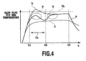
- a tip end temperature of the glow plug 15 shown in a solid line a of Fig. 4 is, as shown in an ellipse p in the figure, lower than an upper limit temperature UL under which the glow plug 15 is not degraded.
- the tip end temperature of the glow plug 15 would, as shown in a chain line b, exceed the upper limit temperature UL, since the deposited unburned component and the supplied fuel both are burned for an initial period of the heating. It should be noted that a dotted line c in Fig. 4 shows a tip end temperature of the glow plug 15 in a case of no deposit of the unburned component and no supply of the fuel.
- the temperature increase by the fuel supply and the heating is started after start of the heating for removal of the deposited unburned component, and also after an elapse of the predetermined suppression time tc.
- the temperature of the glow plug 15 is lowered due to the elapse of the suppression time tc, and therefore the degradation of the heating apparatus can be suitably suppressed with a simple construction.
- the present embodiment further comprises means for obtaining a temperature of the glow plug 15, wherein the ECU 30 executes the temperature increase by the fuel supply and the heating in a case where the temperature of the glow plug 15 is lower than a predetermined upper limit temperature. Therefore, it is guaranteed that the temperature of the glow plug 15 is low at the temperature increasing, thereby making it possible to suitably suppress degradation of the glow plug 15.
- the condition for lifting the suppression of the fuel supply may be one of two conditions that the suppression time tc elapses (S30) and that the glow temperature Tg is lower than the upper limit temperature Ta (S50).
- the present embodiment further comprises the exhaust temperature sensor 18 for obtaining a temperature of the exhaust passage, wherein the fuel supply time ts, as the execution time of the temperature increase, is set to be the shorter as the exhaust temperature Te is higher, and is set to be the shorter as the fuel supply quantity Qf is larger. Therefore, by suppressing the excessive temperature increase, the degradation of the glow plug 15 can be suitably suppressed.
- the fuel injection (after-addition) not accompanied by the heating by the glow plug 15, and the increase of the exhaust flow amount due to the increase of the opening degree of each of the EGR control valve 22 and the throttle valve 4, are performed (S110). Therefore, the tip end of the injector 12 and the glow plug 15 can be quickly cooled (after t3 in Fig. 4 ).
- the after-addition and the increase of the exhaust flow amount only one of them may be performed.
- the increase of the exhaust flow amount may start immediately before the power supply to the glow plug 15 (S20), and in this case, the combustion is made to be performed downstream of the tip end of the glow plug 15, thus suppressing an temperature increase of the tip end.
- the ECU 30 does not perform the supply of the fuel from the injector 12 over the predetermined suppression time tc including the start time of the heating operation of the glow plug 15 (S30).
- supply of the fuel in a quantity smaller than the fuel supply performed at step S90 may be performed for the suppression time tc.
- the fuel supply time ts is set as a function of the exhaust temperature Te and the fuel supply quantity Qf, but may be set as a function of only one of them.
Landscapes
- Engineering & Computer Science (AREA)
- Chemical & Material Sciences (AREA)
- Chemical Kinetics & Catalysis (AREA)
- Combustion & Propulsion (AREA)
- Mechanical Engineering (AREA)
- General Engineering & Computer Science (AREA)
- Health & Medical Sciences (AREA)
- Toxicology (AREA)
- Exhaust Gas After Treatment (AREA)
Claims (3)
- Appareil d'épuration d'échappement pour un moteur à combustion interne comprenant :des moyens d'alimentation en carburant (12) pour fournir du carburant à une conduite d'échappement d'un moteur à combustion interne ;des moyens d'allumage (15) pour brûler le carburant fourni par les moyens d'alimentation en carburant (12) ;des moyens d'augmentation de température (16, 17) pour enflammer le carburant fourni par les moyens d'alimentation en carburant (12) grâce aux moyens d'allumage (15) afin d'augmenter une température d'un gaz d'échappement circulant dans la conduite d'échappement,caractérisé en ce que l'appareil d'épuration d'échappement comprend en outre :un dispositif de commande (30) programmé pour commander les moyens d'alimentation en carburant (12), les moyens d'allumage (15) et les moyens d'augmentation de température (16, 17) ; dans lequelle dispositif de commande (30) est apte à exécuter une opération d'élimination, qui, dans un cas où les éléments non brûlés du gaz d'échappement sont déposés sur les moyens d'allumage (15), commande aux moyens d'augmentation de température (16, 17) de brûler les éléments non brûlés déposés pour les éliminer avant l'exécution de la combustion du carburant par les moyens d'augmentation de température (16, 17) sans fournir le carburant provenant des moyens d'alimentation en carburant (12), et dans lequel :ledit dispositif de commande (30) exécute la combustion du carburant dans une condition prédéterminée, laquelle est au moins l'une des conditions suivantes :qu'un temps de suppression (tc) se soit écoulé suite à l'élimination par l'opération d'élimination, ledit temps de suppression (tc) étant prédéterminé de telle sorte que, même si la combustion du carburant par les moyens d'augmentation de température (16, 17) était exécutée, la température des moyens d'allumage (15) serait inférieure à une température limite supérieure (UL) qui ne détériorerait pas les moyens d'allumage (15) ; etqu'une température (tg) des moyens d'allumage (15) soit inférieure à une température de limite supérieure (Ta), ladite température de limite supérieure (Ta) étant prédéterminée de telle sorte que, même si la combustion du carburant par les moyens d'augmentation de température (16, 17) était exécutée lorsque la température (tg) est inférieure à ladite température limite supérieure (Ta), la température des moyens d'allumage (15) serait inférieure à une température de limite supérieure (UL) qui ne détériorerait pas les moyens d'allumage (15).
- Appareil d'épuration d'échappement pour un moteur à combustion interne selon la revendication 1, comprenant en outre :des moyens pour obtenir une température de la conduite d'échappement, dans lequelles moyens d'augmentation de température (16, 17) raccourcissent le temps d'exécution de la combustion du carburant puisque la température de la conduite d'échappement est supérieure.
- Appareil d'épuration d'échappement pour un moteur à combustion interne selon la revendication 1, comprenant en outre :des moyens pour obtenir une quantité d'alimentation en carburant des moyens d'alimentation en carburant, dans lequelles moyens d'augmentation de température (16, 17) raccourcissent le temps d'exécution de la combustion du carburant puisque la quantité d'alimentation en carburant est plus importante.
Applications Claiming Priority (1)
| Application Number | Priority Date | Filing Date | Title |
|---|---|---|---|
| PCT/JP2009/005570 WO2011048637A1 (fr) | 2009-10-22 | 2009-10-22 | Dispositif d'épuration d'échappement de moteur à combustion interne |
Publications (3)
| Publication Number | Publication Date |
|---|---|
| EP2492463A1 EP2492463A1 (fr) | 2012-08-29 |
| EP2492463A4 EP2492463A4 (fr) | 2013-10-02 |
| EP2492463B1 true EP2492463B1 (fr) | 2015-01-07 |
Family
ID=43899892
Family Applications (1)
| Application Number | Title | Priority Date | Filing Date |
|---|---|---|---|
| EP09850536.5A Not-in-force EP2492463B1 (fr) | 2009-10-22 | 2009-10-22 | Dispositif d'épuration d'échappement de moteur à combustion interne |
Country Status (5)
| Country | Link |
|---|---|
| US (1) | US20120240559A1 (fr) |
| EP (1) | EP2492463B1 (fr) |
| JP (1) | JP5267676B2 (fr) |
| CN (1) | CN102575548B (fr) |
| WO (1) | WO2011048637A1 (fr) |
Families Citing this family (4)
| Publication number | Priority date | Publication date | Assignee | Title |
|---|---|---|---|---|
| WO2013102946A1 (fr) * | 2012-01-04 | 2013-07-11 | トヨタ自動車株式会社 | Procédé de chauffage d'échappement |
| EP2808508B1 (fr) * | 2012-01-27 | 2017-05-31 | Toyota Jidosha Kabushiki Kaisha | Dispositif de commande pour moteur à combustion interne |
| JP2013181452A (ja) * | 2012-03-01 | 2013-09-12 | Nippon Soken Inc | 排気浄化装置 |
| JP5831645B2 (ja) * | 2012-10-31 | 2015-12-09 | トヨタ自動車株式会社 | 内燃機関の運転制御装置および方法 |
Family Cites Families (13)
| Publication number | Priority date | Publication date | Assignee | Title |
|---|---|---|---|---|
| JPS6047816U (ja) * | 1983-09-09 | 1985-04-04 | マツダ株式会社 | デイ−ゼルエンジンの排気浄化装置 |
| DE3502966A1 (de) * | 1984-06-01 | 1985-12-05 | Robert Bosch Gmbh, 7000 Stuttgart | Einrichtung zur steuerung und regelung der temperatur einer gluehkerze |
| JPH06104412B2 (ja) * | 1985-06-11 | 1994-12-21 | いすゞ自動車株式会社 | 燃焼器のスクリ−ニング装置 |
| DE3812299A1 (de) * | 1988-04-13 | 1989-10-26 | Eberspaecher J | Verdampferbrenner und verfahren zum betreiben eines verdampferbrenners |
| JP2874480B2 (ja) * | 1992-09-30 | 1999-03-24 | トヨタ自動車株式会社 | 内燃機関の触媒暖機装置 |
| JP3077418B2 (ja) * | 1992-10-15 | 2000-08-14 | トヨタ自動車株式会社 | 内燃機関の触媒暖機制御装置 |
| JPH0643214U (ja) * | 1992-11-13 | 1994-06-07 | いすゞ自動車株式会社 | パティキュレートトラップの再生装置 |
| DE4243959A1 (de) * | 1992-12-23 | 1994-06-30 | Beru Werk Ruprecht Gmbh Co A | Flammstartanlage für eine Verbrennungseinrichtung |
| JP4348793B2 (ja) | 1999-10-13 | 2009-10-21 | トヨタ自動車株式会社 | 内燃機関の排気浄化装置 |
| JP2004324587A (ja) * | 2003-04-25 | 2004-11-18 | Mitsubishi Fuso Truck & Bus Corp | 内燃機関の排気浄化装置 |
| JP2006112401A (ja) * | 2004-10-18 | 2006-04-27 | Denso Corp | 触媒昇温装置 |
| JP2008291760A (ja) * | 2007-05-25 | 2008-12-04 | Bosch Corp | 液体燃料バーナ及び内燃機関の排気浄化装置 |
| US8183501B2 (en) * | 2007-12-13 | 2012-05-22 | Delphi Technologies, Inc. | Method for controlling glow plug ignition in a preheater of a hydrocarbon reformer |
-
2009
- 2009-10-22 CN CN2009801620653A patent/CN102575548B/zh not_active Expired - Fee Related
- 2009-10-22 EP EP09850536.5A patent/EP2492463B1/fr not_active Not-in-force
- 2009-10-22 JP JP2011537025A patent/JP5267676B2/ja not_active Expired - Fee Related
- 2009-10-22 US US13/502,464 patent/US20120240559A1/en not_active Abandoned
- 2009-10-22 WO PCT/JP2009/005570 patent/WO2011048637A1/fr not_active Ceased
Also Published As
| Publication number | Publication date |
|---|---|
| JP5267676B2 (ja) | 2013-08-21 |
| EP2492463A4 (fr) | 2013-10-02 |
| EP2492463A1 (fr) | 2012-08-29 |
| CN102575548B (zh) | 2013-11-06 |
| CN102575548A (zh) | 2012-07-11 |
| WO2011048637A1 (fr) | 2011-04-28 |
| US20120240559A1 (en) | 2012-09-27 |
| JPWO2011048637A1 (ja) | 2013-03-07 |
Similar Documents
| Publication | Publication Date | Title |
|---|---|---|
| RU2678866C2 (ru) | Двигательная система | |
| US8312712B2 (en) | Electrically heated particulate filter regeneration during engine start/stop operation | |
| US20090044520A1 (en) | Intake Air Heater for Assisting DPF Regeneration | |
| CN100564824C (zh) | 内燃机的排气净化催化剂加热系统及其方法 | |
| EP2218891B1 (fr) | Dispositif de contrôle de la température pour catalyseur | |
| US8950177B2 (en) | Detecting particulate matter load density within a particulate filter | |
| US9206724B2 (en) | Exhaust gas purification system for internal combustion engine | |
| JP2009185628A (ja) | 内燃機関の燃料噴射制御システム | |
| US5784878A (en) | Idle speed control system of internal combustion engine | |
| EP2492463B1 (fr) | Dispositif d'épuration d'échappement de moteur à combustion interne | |
| JP2017155707A (ja) | 内燃機関の排気浄化システム | |
| WO2015033519A1 (fr) | Commande de la régénération d'un filtre à particules de gaz d'échappement | |
| US8341945B2 (en) | Electrically heated particulate filter | |
| US8943814B2 (en) | Warm-up system for exhaust system of internal combustion engine | |
| US8443590B2 (en) | Reduced volume electrically heated particulate filter | |
| JP5418123B2 (ja) | 内燃機関の排気浄化装置 | |
| US9528421B2 (en) | Exhaust device of internal combustion engine | |
| JP2008261323A (ja) | 内燃機関の排気微粒子測定装置に関する。 | |
| JP2005113875A (ja) | ディーゼルエンジンの制御装置 | |
| JP2005133596A (ja) | 内燃機関の排気浄化触媒昇温方法 | |
| JP2013181452A (ja) | 排気浄化装置 | |
| JP2014101777A (ja) | 内燃機関の制御装置 | |
| JP2011026999A (ja) | 触媒暖機制御装置 | |
| JP2017145752A (ja) | 内燃機関の制御装置 | |
| JP2009127516A (ja) | 空燃比センサの制御装置 |
Legal Events
| Date | Code | Title | Description |
|---|---|---|---|
| PUAI | Public reference made under article 153(3) epc to a published international application that has entered the european phase |
Free format text: ORIGINAL CODE: 0009012 |
|
| 17P | Request for examination filed |
Effective date: 20120330 |
|
| AK | Designated contracting states |
Kind code of ref document: A1 Designated state(s): AT BE BG CH CY CZ DE DK EE ES FI FR GB GR HR HU IE IS IT LI LT LU LV MC MK MT NL NO PL PT RO SE SI SK SM TR |
|
| DAX | Request for extension of the european patent (deleted) | ||
| RAP1 | Party data changed (applicant data changed or rights of an application transferred) |
Owner name: TOYOTA JIDOSHA KABUSHIKI KAISHA |
|
| REG | Reference to a national code |
Ref country code: DE Ref legal event code: R079 Ref document number: 602009028903 Country of ref document: DE Free format text: PREVIOUS MAIN CLASS: F01N0003200000 Ipc: F01N0003360000 |
|
| A4 | Supplementary search report drawn up and despatched |
Effective date: 20130903 |
|
| RIC1 | Information provided on ipc code assigned before grant |
Ipc: F01N 3/36 20060101AFI20130828BHEP Ipc: F01N 9/00 20060101ALI20130828BHEP |
|
| 17Q | First examination report despatched |
Effective date: 20140224 |
|
| RIN1 | Information on inventor provided before grant (corrected) |
Inventor name: TSUJIMOTO, KENICHI |
|
| GRAP | Despatch of communication of intention to grant a patent |
Free format text: ORIGINAL CODE: EPIDOSNIGR1 |
|
| INTG | Intention to grant announced |
Effective date: 20140819 |
|
| GRAS | Grant fee paid |
Free format text: ORIGINAL CODE: EPIDOSNIGR3 |
|
| GRAA | (expected) grant |
Free format text: ORIGINAL CODE: 0009210 |
|
| AK | Designated contracting states |
Kind code of ref document: B1 Designated state(s): AT BE BG CH CY CZ DE DK EE ES FI FR GB GR HR HU IE IS IT LI LT LU LV MC MK MT NL NO PL PT RO SE SI SK SM TR |
|
| REG | Reference to a national code |
Ref country code: GB Ref legal event code: FG4D |
|
| REG | Reference to a national code |
Ref country code: CH Ref legal event code: EP |
|
| REG | Reference to a national code |
Ref country code: IE Ref legal event code: FG4D |
|
| REG | Reference to a national code |
Ref country code: AT Ref legal event code: REF Ref document number: 705894 Country of ref document: AT Kind code of ref document: T Effective date: 20150215 |
|
| REG | Reference to a national code |
Ref country code: DE Ref legal event code: R096 Ref document number: 602009028903 Country of ref document: DE Effective date: 20150219 |
|
| REG | Reference to a national code |
Ref country code: NL Ref legal event code: VDEP Effective date: 20150107 |
|
| REG | Reference to a national code |
Ref country code: AT Ref legal event code: MK05 Ref document number: 705894 Country of ref document: AT Kind code of ref document: T Effective date: 20150107 |
|
| REG | Reference to a national code |
Ref country code: LT Ref legal event code: MG4D |
|
| REG | Reference to a national code |
Ref country code: DE Ref legal event code: R084 Ref document number: 602009028903 Country of ref document: DE |
|
| PG25 | Lapsed in a contracting state [announced via postgrant information from national office to epo] |
Ref country code: HR Free format text: LAPSE BECAUSE OF FAILURE TO SUBMIT A TRANSLATION OF THE DESCRIPTION OR TO PAY THE FEE WITHIN THE PRESCRIBED TIME-LIMIT Effective date: 20150107 Ref country code: NO Free format text: LAPSE BECAUSE OF FAILURE TO SUBMIT A TRANSLATION OF THE DESCRIPTION OR TO PAY THE FEE WITHIN THE PRESCRIBED TIME-LIMIT Effective date: 20150407 Ref country code: SE Free format text: LAPSE BECAUSE OF FAILURE TO SUBMIT A TRANSLATION OF THE DESCRIPTION OR TO PAY THE FEE WITHIN THE PRESCRIBED TIME-LIMIT Effective date: 20150107 Ref country code: FI Free format text: LAPSE BECAUSE OF FAILURE TO SUBMIT A TRANSLATION OF THE DESCRIPTION OR TO PAY THE FEE WITHIN THE PRESCRIBED TIME-LIMIT Effective date: 20150107 Ref country code: BG Free format text: LAPSE BECAUSE OF FAILURE TO SUBMIT A TRANSLATION OF THE DESCRIPTION OR TO PAY THE FEE WITHIN THE PRESCRIBED TIME-LIMIT Effective date: 20150407 Ref country code: ES Free format text: LAPSE BECAUSE OF FAILURE TO SUBMIT A TRANSLATION OF THE DESCRIPTION OR TO PAY THE FEE WITHIN THE PRESCRIBED TIME-LIMIT Effective date: 20150107 Ref country code: LT Free format text: LAPSE BECAUSE OF FAILURE TO SUBMIT A TRANSLATION OF THE DESCRIPTION OR TO PAY THE FEE WITHIN THE PRESCRIBED TIME-LIMIT Effective date: 20150107 |
|
| PG25 | Lapsed in a contracting state [announced via postgrant information from national office to epo] |
Ref country code: GR Free format text: LAPSE BECAUSE OF FAILURE TO SUBMIT A TRANSLATION OF THE DESCRIPTION OR TO PAY THE FEE WITHIN THE PRESCRIBED TIME-LIMIT Effective date: 20150408 Ref country code: AT Free format text: LAPSE BECAUSE OF FAILURE TO SUBMIT A TRANSLATION OF THE DESCRIPTION OR TO PAY THE FEE WITHIN THE PRESCRIBED TIME-LIMIT Effective date: 20150107 Ref country code: IS Free format text: LAPSE BECAUSE OF FAILURE TO SUBMIT A TRANSLATION OF THE DESCRIPTION OR TO PAY THE FEE WITHIN THE PRESCRIBED TIME-LIMIT Effective date: 20150507 Ref country code: PL Free format text: LAPSE BECAUSE OF FAILURE TO SUBMIT A TRANSLATION OF THE DESCRIPTION OR TO PAY THE FEE WITHIN THE PRESCRIBED TIME-LIMIT Effective date: 20150107 Ref country code: LV Free format text: LAPSE BECAUSE OF FAILURE TO SUBMIT A TRANSLATION OF THE DESCRIPTION OR TO PAY THE FEE WITHIN THE PRESCRIBED TIME-LIMIT Effective date: 20150107 Ref country code: NL Free format text: LAPSE BECAUSE OF FAILURE TO SUBMIT A TRANSLATION OF THE DESCRIPTION OR TO PAY THE FEE WITHIN THE PRESCRIBED TIME-LIMIT Effective date: 20150107 |
|
| REG | Reference to a national code |
Ref country code: DE Ref legal event code: R097 Ref document number: 602009028903 Country of ref document: DE |
|
| PG25 | Lapsed in a contracting state [announced via postgrant information from national office to epo] |
Ref country code: RO Free format text: LAPSE BECAUSE OF FAILURE TO SUBMIT A TRANSLATION OF THE DESCRIPTION OR TO PAY THE FEE WITHIN THE PRESCRIBED TIME-LIMIT Effective date: 20150107 Ref country code: DK Free format text: LAPSE BECAUSE OF FAILURE TO SUBMIT A TRANSLATION OF THE DESCRIPTION OR TO PAY THE FEE WITHIN THE PRESCRIBED TIME-LIMIT Effective date: 20150107 Ref country code: SK Free format text: LAPSE BECAUSE OF FAILURE TO SUBMIT A TRANSLATION OF THE DESCRIPTION OR TO PAY THE FEE WITHIN THE PRESCRIBED TIME-LIMIT Effective date: 20150107 Ref country code: CZ Free format text: LAPSE BECAUSE OF FAILURE TO SUBMIT A TRANSLATION OF THE DESCRIPTION OR TO PAY THE FEE WITHIN THE PRESCRIBED TIME-LIMIT Effective date: 20150107 Ref country code: EE Free format text: LAPSE BECAUSE OF FAILURE TO SUBMIT A TRANSLATION OF THE DESCRIPTION OR TO PAY THE FEE WITHIN THE PRESCRIBED TIME-LIMIT Effective date: 20150107 |
|
| PLBE | No opposition filed within time limit |
Free format text: ORIGINAL CODE: 0009261 |
|
| STAA | Information on the status of an ep patent application or granted ep patent |
Free format text: STATUS: NO OPPOSITION FILED WITHIN TIME LIMIT |
|
| 26N | No opposition filed |
Effective date: 20151008 |
|
| PG25 | Lapsed in a contracting state [announced via postgrant information from national office to epo] |
Ref country code: IT Free format text: LAPSE BECAUSE OF FAILURE TO SUBMIT A TRANSLATION OF THE DESCRIPTION OR TO PAY THE FEE WITHIN THE PRESCRIBED TIME-LIMIT Effective date: 20150107 |
|
| PG25 | Lapsed in a contracting state [announced via postgrant information from national office to epo] |
Ref country code: SI Free format text: LAPSE BECAUSE OF FAILURE TO SUBMIT A TRANSLATION OF THE DESCRIPTION OR TO PAY THE FEE WITHIN THE PRESCRIBED TIME-LIMIT Effective date: 20150107 |
|
| PG25 | Lapsed in a contracting state [announced via postgrant information from national office to epo] |
Ref country code: BE Free format text: LAPSE BECAUSE OF FAILURE TO SUBMIT A TRANSLATION OF THE DESCRIPTION OR TO PAY THE FEE WITHIN THE PRESCRIBED TIME-LIMIT Effective date: 20150107 Ref country code: LU Free format text: LAPSE BECAUSE OF FAILURE TO SUBMIT A TRANSLATION OF THE DESCRIPTION OR TO PAY THE FEE WITHIN THE PRESCRIBED TIME-LIMIT Effective date: 20151022 |
|
| REG | Reference to a national code |
Ref country code: CH Ref legal event code: PL |
|
| GBPC | Gb: european patent ceased through non-payment of renewal fee |
Effective date: 20151022 |
|
| PG25 | Lapsed in a contracting state [announced via postgrant information from national office to epo] |
Ref country code: MC Free format text: LAPSE BECAUSE OF FAILURE TO SUBMIT A TRANSLATION OF THE DESCRIPTION OR TO PAY THE FEE WITHIN THE PRESCRIBED TIME-LIMIT Effective date: 20150107 |
|
| REG | Reference to a national code |
Ref country code: IE Ref legal event code: MM4A |
|
| PG25 | Lapsed in a contracting state [announced via postgrant information from national office to epo] |
Ref country code: GB Free format text: LAPSE BECAUSE OF NON-PAYMENT OF DUE FEES Effective date: 20151022 Ref country code: CH Free format text: LAPSE BECAUSE OF NON-PAYMENT OF DUE FEES Effective date: 20151031 Ref country code: LI Free format text: LAPSE BECAUSE OF NON-PAYMENT OF DUE FEES Effective date: 20151031 |
|
| REG | Reference to a national code |
Ref country code: FR Ref legal event code: ST Effective date: 20160630 |
|
| PG25 | Lapsed in a contracting state [announced via postgrant information from national office to epo] |
Ref country code: FR Free format text: LAPSE BECAUSE OF NON-PAYMENT OF DUE FEES Effective date: 20151102 |
|
| PG25 | Lapsed in a contracting state [announced via postgrant information from national office to epo] |
Ref country code: IE Free format text: LAPSE BECAUSE OF NON-PAYMENT OF DUE FEES Effective date: 20151022 |
|
| PG25 | Lapsed in a contracting state [announced via postgrant information from national office to epo] |
Ref country code: HU Free format text: LAPSE BECAUSE OF FAILURE TO SUBMIT A TRANSLATION OF THE DESCRIPTION OR TO PAY THE FEE WITHIN THE PRESCRIBED TIME-LIMIT; INVALID AB INITIO Effective date: 20091022 Ref country code: SM Free format text: LAPSE BECAUSE OF FAILURE TO SUBMIT A TRANSLATION OF THE DESCRIPTION OR TO PAY THE FEE WITHIN THE PRESCRIBED TIME-LIMIT Effective date: 20150107 |
|
| PG25 | Lapsed in a contracting state [announced via postgrant information from national office to epo] |
Ref country code: CY Free format text: LAPSE BECAUSE OF FAILURE TO SUBMIT A TRANSLATION OF THE DESCRIPTION OR TO PAY THE FEE WITHIN THE PRESCRIBED TIME-LIMIT Effective date: 20150107 |
|
| PG25 | Lapsed in a contracting state [announced via postgrant information from national office to epo] |
Ref country code: TR Free format text: LAPSE BECAUSE OF FAILURE TO SUBMIT A TRANSLATION OF THE DESCRIPTION OR TO PAY THE FEE WITHIN THE PRESCRIBED TIME-LIMIT Effective date: 20150107 Ref country code: MT Free format text: LAPSE BECAUSE OF FAILURE TO SUBMIT A TRANSLATION OF THE DESCRIPTION OR TO PAY THE FEE WITHIN THE PRESCRIBED TIME-LIMIT Effective date: 20150107 |
|
| PG25 | Lapsed in a contracting state [announced via postgrant information from national office to epo] |
Ref country code: MK Free format text: LAPSE BECAUSE OF FAILURE TO SUBMIT A TRANSLATION OF THE DESCRIPTION OR TO PAY THE FEE WITHIN THE PRESCRIBED TIME-LIMIT Effective date: 20150107 Ref country code: PT Free format text: LAPSE BECAUSE OF FAILURE TO SUBMIT A TRANSLATION OF THE DESCRIPTION OR TO PAY THE FEE WITHIN THE PRESCRIBED TIME-LIMIT Effective date: 20150107 |
|
| PGFP | Annual fee paid to national office [announced via postgrant information from national office to epo] |
Ref country code: DE Payment date: 20181009 Year of fee payment: 10 |
|
| REG | Reference to a national code |
Ref country code: DE Ref legal event code: R119 Ref document number: 602009028903 Country of ref document: DE |
|
| PG25 | Lapsed in a contracting state [announced via postgrant information from national office to epo] |
Ref country code: DE Free format text: LAPSE BECAUSE OF NON-PAYMENT OF DUE FEES Effective date: 20200501 |