EP2492423B1 - Barrier with opening trends - Google Patents
Barrier with opening trends Download PDFInfo
- Publication number
- EP2492423B1 EP2492423B1 EP12001330.5A EP12001330A EP2492423B1 EP 2492423 B1 EP2492423 B1 EP 2492423B1 EP 12001330 A EP12001330 A EP 12001330A EP 2492423 B1 EP2492423 B1 EP 2492423B1
- Authority
- EP
- European Patent Office
- Prior art keywords
- pawl
- motor vehicle
- vehicle door
- lever
- rotary latch
- Prior art date
- Legal status (The legal status is an assumption and is not a legal conclusion. Google has not performed a legal analysis and makes no representation as to the accuracy of the status listed.)
- Active
Links
Images


Classifications
-
- E—FIXED CONSTRUCTIONS
- E05—LOCKS; KEYS; WINDOW OR DOOR FITTINGS; SAFES
- E05B—LOCKS; ACCESSORIES THEREFOR; HANDCUFFS
- E05B77/00—Vehicle locks characterised by special functions or purposes
- E05B77/36—Noise prevention; Anti-rattling means
-
- E—FIXED CONSTRUCTIONS
- E05—LOCKS; KEYS; WINDOW OR DOOR FITTINGS; SAFES
- E05B—LOCKS; ACCESSORIES THEREFOR; HANDCUFFS
- E05B85/00—Details of vehicle locks not provided for in groups E05B77/00 - E05B83/00
- E05B85/20—Bolts or detents
- E05B85/24—Bolts rotating about an axis
- E05B85/26—Cooperation between bolts and detents
-
- E—FIXED CONSTRUCTIONS
- E05—LOCKS; KEYS; WINDOW OR DOOR FITTINGS; SAFES
- E05B—LOCKS; ACCESSORIES THEREFOR; HANDCUFFS
- E05B15/00—Other details of locks; Parts for engagement by bolts of fastening devices
- E05B15/04—Spring arrangements in locks
- E05B2015/0403—Wound springs
- E05B2015/0406—Wound springs wound in a cylindrical shape
- E05B2015/041—Wound springs wound in a cylindrical shape loaded perpendicular to cylinder axis
Definitions
- the present invention relates to a locking mechanism for a motor vehicle door according to the preamble of claim 1.
- motor vehicle door is to be interpreted comprehensively and also includes motor vehicle flaps, covers, sliding doors, hoods and all closure elements that cover openings in a vehicle.
- EP 2 161 398 A2 is a barrier with a catch, an intermediate lever and a pawl mounted thereon known.
- a locking mechanism shown that includes a rotary latch, which is loaded by a spring in the opening direction.
- This catch is positively locked in the closed state by a pawl.
- the pawl is pivotally mounted on a pawl lever and loaded by a spring in the blocking direction to the catch.
- the pawl lever is loaded by another spring in the opening direction.
- the opening of the lock is prevented by the positive connection to a locking lever.
- the locking lever is loaded by a further spring in the closing direction.
- This locking lever can be brought by means of a solenoid out of engagement with the pawl lever, so that the pawl lever pivots with the pawl of the engagement region of the rotary latch and this opens.
- the striker not shown, rotates the catch in the closing direction. Only the pawl, without pawl lever moves in the opening direction and closed immediately by the pawl spring.
- the pawl and the rotary latch are arranged to each other such that the rotary latch on the pawl generates a torque in the opening direction.
- This is indicated by the force parallelogram in Fig. 2 of the US 3,386,761 shown in detail.
- this arrangement has the disadvantage that the pawl can move in the opening direction with strong vibration forces. By the movement of the pawl in the opening direction of the blocking of the catch is released, so that the lock and thus the vehicle door can open.
- the invention has for its object to provide a barrier, which has a low noise when closing, but keeps the door safely in the closed position even with vibration and other mechanical influences.
- the barrier invention is characterized by the features specified in claim 1. Details of the invention will become apparent from the dependent claims.
- the blocking mechanism according to the invention consists i.a. from a catch and a pawl mechanism, which are usually part of a motor vehicle lock.
- motor vehicle locks hold in conjunction with a striker vehicle doors, trunk lid, trunk hoods, hoods, trunk lid or sliding doors in the closed position, or can be opened by means of the locks.
- motor vehicle door stands for all elements that cover openings in vehicles.
- the locks with the locking mechanisms are usually mounted in the doors, with the corresponding firing bracket to the body, preferably on the B or C-pillar is attached.
- the lock with the locking mechanism is attached to the body, wherein the striker on the moving part, the trunk lid is complained.
- the positioning of the components thus has no influence on the invention.
- all elements are designated, e.g. also locking bolts or strikers, which form a positive connection with the locking mechanism.
- the locking mechanism consists of a rotary latch and a pawl mechanism.
- the catch is in closed door with the striker in positive connection. When opening the door, this positive connection is released.
- the catch is preferably a U-shaped element which is pivotally mounted.
- a spring loads the catch in the opening direction.
- the striker presses on one leg of the U-shaped rotary latch, whereby the other leg of the rotary latch rotates around the striker and thus forms a positive connection with the striker.
- This position of the catch is when the door is closed fixed by a pawl. Both the pawl spring and the door seal exert pressure on the pawl via the striker and the catch.
- this loading direction is referred to as "in the closing direction”.
- the opening direction the direction of movement is referred to, in which the rotary latch pushes the pawl, or the pawl assembly in the direction in which the pawl is disengaged from the catch.
- the essence of the invention is now to arrange the contact surfaces between the catch, pawl and pawl lever, and their pivot points such that the force of the catch acting on the pawl, generates a torque which enhances the blocking between pawl and rotary latch. At the same time generates the same force of the rotary latch, a torque on the assembly of pawl lever and pawl, through which the assembly of pawl lever and pawl is loaded in the opening direction.
- the force transmitted by the catch to the pawl is generated by a rotary latch spring and the door seal.
- the rotary latch spring engages directly on the rotary latch and generates a torque that loads the rotary latch in the opening direction.
- a much higher force is generated by the door seal when the door is closed.
- the door seal which is arranged between the body and the door, generates a force on the door structure, also referred to as a door frame, on the lock, in particular on the locking mechanism, in particular on the catch.
- the rotary latch is in positive connection with the striker, whereby the power flow is closed.
- the force thus generated is transmitted from the catch to the pawl or to the assembly of pawl lever and pawl.
- Both pawl and pawl lever are loaded by a spring in the direction of the catch.
- the pawl is shaped so that it is mounted on the pawl lever and welißt a contour which is in positive connection with a contour of the pawl lever.
- the spring force of the rotary latch spring is now transmitted to this contour of the pawl and directly on the pawl lever contour on the pawl lever, which is thereby loaded in the direction of the rotary latch.
- Both rotary latch and pawl and pawl lever are designed such that the rotary latch on the assembly of pawl lever and pawl generates a torque that loads the assembly in the opening direction.
- the movement of the pawl pawl lever assembly in the opening direction is prevented by the locking lever. This is done by the locking lever blocking the pawl lever in the opening direction.
- the locking lever is pivoted out of the path of the pawl lever, whereby the positive engagement is released and the pawl-pawl lever assembly moves in the opening direction.
- the locking lever is loaded by a spring in the direction in which it blocks the pawl lever. By a motor drive or manually, the locking lever can be disengaged from the pawl lever.
- the opening operation described above is always associated with the fact that the engagement between the pawl and the catch is canceled. This can be done in a pulse-like manner in a preferred variant by the pawl is pulled out of the range of motion of the rotary latch. This type of lifting the pawl is always associated with a corresponding pulse-like noise.
- the opening operation is accompanied by a rolling movement of the pawl on the rotary latch. Further preferably, the pawl rotates in the course of the rolling movement of the main catch or pre-catch the catch out. The rolling movement described above ensures that a pulse-like noise by canceling the engagement between pawl and rotary latch does not occur.
- a motor vehicle door lock is claimed with a barrier.
- the proposed motor vehicle door lock can be positioned in a motor vehicle door or in a door frame.
- the motor vehicle door lock keeps the motor vehicle door closed in conjunction with a striker positioned on the door frame or door or opens the motor vehicle door accordingly, with a detent having a catch positively connected to the striker when the motor vehicle door is closed, with a detent pawl holding the catch closed motor vehicle door, in a pre-locking position or a main detent position, blocked and with an assembly consisting of a pivotable intermediate lever and the pivotally mounted therein pawl which blocks the catch when the vehicle door is closed, in a pre-locked position or a main detent position.
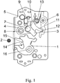
- Fig. 1 shows an inventive locking mechanism in the open position.
- the firing bow 2 is not in engagement with the rotary latch 1.
- the pawl 3 is mounted on the pawl mandrel 7, wherein the pawl mandrel 7 is positioned on the pawl lever 4.
- the pawl lever 4 is pivotally mounted on a mandrel 8.
- the force of the pawl spring 5 engages the lever arm 9 of the pawl 3 and is transmitted to the lever arm 10 of the pawl lever 4. This causes a movement of the pawl lever 4 in a clockwise direction.
- the movement of the pawl lever 4 is stopped via the Blockadehebelarm 11 which abuts against the contour 12 of the locking lever 6.
- a locking lever spring 13 loads the locking lever 6 in the closing direction.
- the striker 2 moves, as in Fig. 2
- the striker 2 presses on the contour 15 of the catch 1, whereby the catch 1 moves around the rotary mandrel 16 in the closing direction.
- the contour 18 of the rotary latch pivots the pawl 3 on the contour 17 in the counterclockwise direction in the opening direction.
- This is done against the force of the pawl spring 5 is particularly clear in Fig. 2 in that, during the closing operation, only the pawl 3 pivots about the pawl mandrel 7, the pawl lever 4 remaining in its position.
- the pawl 3 falls due to the spring force of the spring 5 back to its original position (see Fig. 3 ). Due to the low mass of the pawl 3 is formed when hitting the pawl lever 4 only a slight noise.
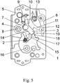
- Fig. 3 the locking mechanism is shown in closed position.
- the rotary latch 1 presses on the pressure contour 23 on the locking contour 19 of the pawl third
- the point of attack on the pawl contour 19, on which the pressure contour 23 of the catch 1 engages and the pivot point 7 is mounted on the pawl 1, are arranged to each other that the lever arm 9 of the pawl 3, the lever arm 10 of the pawl lever 4 charged.
- the locking lever 6 blocked with the contour 12 on the blocking arm 11, the pawl lever 4. Due to this assignment blocks the pawl 3 in conjunction with the pawl lever 4 and the locking lever 6, the movement of the catch 1 in the open position.
- Fig. 4 is the rotary latch 1, the pawl 3, the pawl lever 4 and the locking lever 6 is shown enlarged.
- the direction of the force exerted by the rotary latch 1 on the pawl 3 is shown in this view by the arrow 20.
- the force direction 20 extends between the pivot point 7 of the pawl 3 and the pivot point 8 of the pawl lever 4. This causes the pawl 3, a clockwise torque is generated. Even with vibrations, the pawl 3 always tries to move in the clockwise direction. However, this movement of the pawl 3 is positively locked by the lever arm 10 of the pawl lever 4 and the lever arm 9 of the pawl 3. Thus, a torque in the closing direction is generated on the pawl 3 in the closed position. On the other hand, if a torque is generated counterclockwise, the pawl can escape against the spring force of the pawl spring 5. In this case, a torque is generated in the opening direction.
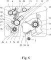
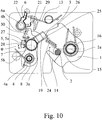
- the Fig. 6 to 10 show a locking mechanism according to the invention in a further embodiment.
- the basic function of the components catch 1, pawl 3, pawl lever 4 and locking lever 6 corresponds to the basic function of the corresponding components in the Fig. 1 to 5 illustrated barrier. Accordingly, it is also in the in the Fig. 6 to 10 Locking mechanism shown around a locking mechanism for a motor vehicle door lock, which is positioned in the mounted state in a motor vehicle door or in a door frame and then holds the motor vehicle door closed or opens in conjunction with a positioned on the door frame or door shooting bracket 2.
- the following is the operation of the in the Fig. 6 to 10 illustrated, the term used in the claims "intermediate lever” again corresponds to the term used in the description "pawl lever".
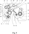
- the barrier is equipped with a rotary latch 1, which is positively connected with the vehicle door closed with the striker 2 ( Fig. 8 ).
- a pawl 3 is provided, which the catch 1 with the vehicle door closed in a pre-locked position, not shown or in Fig. 8 shown blocked main position.
- a pawl lever 4 (intermediate lever 4) and the above pawl 3 form an assembly.
- the direction of the force of the rotary latch 1 on the pawl 3 transmitting force is in Fig. 8 indicated by the reference numeral 20. From this representation shows that it is also in the in the Fig. 6 to 10 illustrated embodiment is such that the rotary latch 1 when the vehicle door is closed, the pawl 3 in the closing direction, in Fig. 8 relative to the pawl lever 4 in the clockwise direction, but charged, but also the assembly of pawl lever 4 and pawl 3 total in the opening direction, in Fig. 8 otherwise counterclockwise, loaded relative to the blocking mechanism.
- the pawl 3 is pivotally mounted on the pawl lever 4 about a pawl axis 3a.
- the pawl lever 4 is pivotally mounted about a pawl lever axis 4a on a fixed part of the motor vehicle door lock, in particular on a housing part of the motor vehicle door lock.
- the catch 1 is according to a rotary latch axis la in turn on a fixed part, in particular on a housing part of the motor vehicle door lock, pivotally mounted.
- a first difference in the Fig. 6 to 10 illustrated embodiment with respect to in the Fig. 1 to 5 illustrated embodiment is that the pawl 3 is coupled relative to the pawl lever 4 with a first spring assembly 5a and that the pawl lever 4 is coupled relative to a fixed part by means of a second spring arrangement 5b.
- the mode of action of the two spring arrangements 5a, 5b will be explained in detail below.
- a locking lever 6 is provided, the pawl lever 4 against movement in the opening direction, in Fig. 8 counterclockwise, blocked.
- the pawl lever 8 is for releasing the locking engagement with the locking lever 6 about a locking lever axis 6a, in Fig. 8 counterclockwise, swiveling.
- the locking lever 6 is closed by the locking lever spring 13 in the closing direction, in Fig. 8 clockwise, biased.
- the pawl 3 on the pawl lever 4 from a sunken position out in which the pawl 3, the catch 1 in the main latching position and in the possibly present pre-locked position ( Fig. 8 ), both in the closing direction (in Fig. 8 clockwise) as well as in the opening direction (in Fig. 8 counterclockwise), here it is pivotable. Any kind of stop the relative movement of the pawl 3 on the pawl lever 4 is therefore not provided.
- the pawl 3 with respect to both directions of movement in a middle position here and preferably in Essentially in the sunken position, biased. The middle position is best described according to Fig. 6 remove.
- the closing process in which in the Fig. 6 to 10 illustrated embodiment corresponds essentially to the closing process in which in the Fig. 1 to 5 illustrated embodiment.
- the striker 2 moves into the inlet mouth 14 of the rotary latch 1, wherein the catch 1 moves around the rotary latch axis 1a in the closing direction.
- the contour 18 of the rotary latch 1 pivots the pawl 3 on the contour 17 in Fig. 6 counterclockwise in the opening direction relative to the pawl lever 4, which takes place against the force of the first spring assembly 5a.
- Fig. 8 shows the state in which the pawl 3 has fallen due to the spring force of the spring assembly 5a in its original position.
- the opening operation which is made up of the sequence of Fig. 8 . 9 and 10 results.
- the main catch 25 and the pre-catch 26 serve to take the main rest position or the pre-locking position by the catch 1, in that the pawl 3 is in blocking engagement with the main catch 25 or the pre-catch 26 when the catch 1 is in the main catch position or in the pre-engaged position.
- rolling motion is to be understood in the present case. This is not only a pure “rolling” of the pawl 3 relative to the catch 1 meant, but also a mixture of rolling and sliding movement between pawl 3 and catch 1. With such a rolling motion can be impulsive noises when canceling the engagement between pawl 3 and Avoid catch 1 as far as possible.
- the spring arrangement 5a is a so-called center-zero spring, which allows a deflection of the pawl 3 out of the middle position in both pivoting directions, in each case against the spring force of the spring arrangement 5a.
- the pawl 3 here and preferably has a driver 27 which is aligned in the middle position to a corresponding driver 28. Both drivers 27, 28 are, as from the Fig. 6 to 10 seen, coupled to the spring assembly 5a.
- the second spring arrangement 5b is used in accordance with the bias of the pawl lever 4 in the closing direction, in Fig. 6 clockwise.
- the opening process is now based on the state of the closed motor vehicle door, in which the locking lever 6, the pawl lever 4 against movement in the opening direction, in Fig. 8 blocked against counterclockwise movement.
- the opening process is triggered by the locking lever 6 in a non-blocking position, in Fig. 8 counterclockwise, in in the Fig. 9 shown position is moved.
- the rotary latch 1 drives the pawl 3 on the pawl lever 4 in the closing direction (in Fig. 9 clockwise).
- the rotary latch 1 drives the pawl lever 4 in the opening direction, in Fig. 9 counterclockwise.
- the locking lever 6 is coupled or coupled to the pawl lever 4 so that the locking lever 6, here and preferably independently of its position, limits the movement of the pawl lever 4 in the closing direction.
- the locking lever 6 and the pawl lever 4 each have an engagement contour 29, 30 which extend here and preferably concentrically to the locking lever axis 6a and which are engaged or engageable with each other for the above coupling.
- this movement limit is guaranteed by a corresponding length of the engagement contours 29, 30 regardless of the position of the locking lever 6.
- an engagement contour 29, 30 is provided exclusively on the locking lever 6 or exclusively on the pawl lever 4. Such a contour would then interact with a corresponding driver o. The like.
- the other lever is coupled or coupled to the pawl lever 4 so that the locking lever 6, here and preferably independently of its position, limits the movement of the pawl lever 4 in the closing direction.
- the locking lever 6 and the pawl lever 4 each have an engagement contour 29, 30 which extend here and preferably concentrically to the locking lever axis 6
- a proposed motor vehicle door lock is claimed as such with a proposed barrier.
Landscapes
- Lock And Its Accessories (AREA)
Description
Die vorliegende Erfindung betrifft ein Sperrwerk für eine Kraftfahrzeugtür gemäß dem Oberbegriff des Anspruchs 1. Dabei ist der Begriff Kraftfahrzeugtür umfassend zu deuten und beinhaltet auch Kraftfahrzeug-Klappen, -Deckel, Schiebetüren, Motorhauben und alle Verschlusselemente, die in einem Fahrzeug Öffnungen abdecken.The present invention relates to a locking mechanism for a motor vehicle door according to the preamble of
In der
In der
In dieser Ausführungsform sind jedoch die Sperrklinke und die Drehfalle derart zueinander angeordnet, dass die Drehfalle auf die Sperrklinke ein Drehmoment in Öffnungsrichtung erzeugt. Dies wird durch das Kräfteparallelogramm in
Der Erfindung liegt die Aufgabe zugrunde, ein Sperrwerk zu schaffen, welches beim Schließen eine geringe Geräuschentwicklung hat, jedoch auch bei Vibrationen und anderen mechanischen Einflüssen die Tür sicher in geschlossener Position hält.The invention has for its object to provide a barrier, which has a low noise when closing, but keeps the door safely in the closed position even with vibration and other mechanical influences.
Zur Lösung dieser Aufgabe zeichnet sich das erfindungsgemäße Sperrwerk durch die im Patentanspruch 1 angegebenen Merkmale aus. Details der Erfindung ergeben sich aus den Unteransprüchen.To solve this problem, the barrier invention is characterized by the features specified in
Das erfindungsgemäße Sperrwerk besteht u.a. aus einer Drehfalle und einer Sperrklinken-mechanik, die meist Bestandteil eines Kraftfahrzeugschlosses sind. Diese Kraftfahrzeug-schlösser halten in Verbindung mit einem Schließbügel Kraftfahrzeugtüren, -Kofferraumdeckel, Kofferraumhauben, Motorhauben, Heckdeckel oder Schiebetüren in geschlossener Position, bzw. lassen sich mittels der Schlösser öffnen. Dabei steht der Begriff Kraftfahrzeugtür für alle Elemente, die Öffnungen in Fahrzeugen abdecken.The blocking mechanism according to the invention consists i.a. from a catch and a pawl mechanism, which are usually part of a motor vehicle lock. These motor vehicle locks hold in conjunction with a striker vehicle doors, trunk lid, trunk hoods, hoods, trunk lid or sliding doors in the closed position, or can be opened by means of the locks. The term motor vehicle door stands for all elements that cover openings in vehicles.
Bei Seitentüren sind die Schlösser mit den Sperrwerken meist in den Türen montiert, wobei der korrespondierende Schießbügel an der Karosserie, vorzugsweise an der B- oder C-Säule, befestigt ist. Bei Heckklappendeckeln hingegen ist das Schloss mit dem Sperrwerk an der Karosserie befestigt, wobei der Schließbügel am beweglichen Teil, dem Heckdeckel moniert ist. Die Positionierung der Komponenten hat somit keinen Einfluss auf die Erfindung. Das gleiche gilt für die geometrische Form des Schließbügels. Als Schließbügel werden alle Elemente bezeichnet, z.B. auch Schließbolzen oder Schließkeile, die mit dem Sperrwerk eine formschlüssige Verbindung eingehen.For side doors, the locks with the locking mechanisms are usually mounted in the doors, with the corresponding firing bracket to the body, preferably on the B or C-pillar is attached. In tailgate lids, however, the lock with the locking mechanism is attached to the body, wherein the striker on the moving part, the trunk lid is complained. The positioning of the components thus has no influence on the invention. The same applies to the geometric shape of the striker. As a striker, all elements are designated, e.g. also locking bolts or strikers, which form a positive connection with the locking mechanism.
Das erfindungsgemäße Sperrwerk besteht aus einer Drehfalle und einer Sperrklinkenmechanik. Die Drehfalle steht bei geschlossener Tür mit dem Schließbügel in formschlüssiger Verbindung. Beim Öffnen der Tür wird dieser Formschluss gelöst. Die Drehfalle ist vorzugs-weise ein U-förmiges Element, das schwenkbar gelagert ist. Eine Feder belastet die Drehfalle in Öffnungsrichtung. Beim Schließvorgang drückt der Schließbügel auf einen Schenkel der U-förmigen Drehfalle, wodurch der andere Schenkel der Drehfalle um, den Schließbügel rotiert und damit eine formschlüssige Verbindung mit dem Schließbügel eingeht. Diese Position der Drehfalle wird bei geschlossener Tür durch eine Sperrklinke fixiert. Sowohl die Sperrklinkenfeder, als auch die Türdichtung üben über den Schließbügel und die Drehfalle Druck auf die Sperrklinke aus. Erzeugt die Kraft der Drehfalle auf die Sperrklinke ein Drehmoment, das den Formschluss zwischen Sperrklinke und Drehfalle stabilisiert, z.B. weil die Drehfalle die Sperrklinke gegen einen festen Anschlag drückt, wird diese Belastungsrichtung als "in Schließrichtung" bezeichnet. Als Öffnungsrichtung wird die Bewegungsrichtung bezeichnet, bei der die Drehfalle die Sperrklinke, bzw. die Sperrklinkenbaugruppe in die Richtung drückt, in der die Sperrklinke außer Eingriff mit der Drehfalle gebracht wird.The locking mechanism according to the invention consists of a rotary latch and a pawl mechanism. The catch is in closed door with the striker in positive connection. When opening the door, this positive connection is released. The catch is preferably a U-shaped element which is pivotally mounted. A spring loads the catch in the opening direction. During the closing process, the striker presses on one leg of the U-shaped rotary latch, whereby the other leg of the rotary latch rotates around the striker and thus forms a positive connection with the striker. This position of the catch is when the door is closed fixed by a pawl. Both the pawl spring and the door seal exert pressure on the pawl via the striker and the catch. Generated the force of the catch on the pawl a torque that stabilizes the positive connection between pawl and rotary latch, for example, because the catch presses the pawl against a fixed stop, this loading direction is referred to as "in the closing direction". As the opening direction, the direction of movement is referred to, in which the rotary latch pushes the pawl, or the pawl assembly in the direction in which the pawl is disengaged from the catch.
Der Kernpunkt der Erfindung besteht nun darin, die Kontaktflächen zwischen Drehfalle, Sperrklinke und Sperrklinkenhebel, und deren Drehpunkte derart anzuordnen, dass die Kraft der Drehfalle, die auf die Sperrklinke wirkt, ein Drehmoment erzeugt, das die Blockierung zwischen Sperrklinke und Drehfalle verstärkt. Gleichzeitig erzeugt die gleiche Kraft der Drehfalle, ein Drehmoment auf die Baugruppe von Sperrklinkenhebel und Sperrklinke, durch die die Baugruppe aus Sperrklinkenhebel und Sperrklinke in Öffnungsrichtung belastet ist.The essence of the invention is now to arrange the contact surfaces between the catch, pawl and pawl lever, and their pivot points such that the force of the catch acting on the pawl, generates a torque which enhances the blocking between pawl and rotary latch. At the same time generates the same force of the rotary latch, a torque on the assembly of pawl lever and pawl, through which the assembly of pawl lever and pawl is loaded in the opening direction.
Erzeugt wird die Kraft, die von der Drehfalle auf die Sperrklinke übertragen wird, von einer Drehfallenfeder und der Türdichtung. Die Drehfallenfeder greift direkt an der Drehfalle an und erzeugt ein Drehmoment das die Drehfalle in Öffnungsrichtung belastet. Eine weitaus höhere Kraft wird, bei geschlossener Tür, durch die Türdichtung erzeugt. Die Türdichtung, die zwischen Karosserie und Tür angeordnet ist, erzeugt eine Kraft über die Türstruktur, auch als Türrahmen bezeichnet, auf das Schloss, insbesondere auf das Sperrwerk, insbesondere auf die Drehfalle. Bei geschlossener Tür steht die Drehfalle in formschlüssiger Verbindung mit dem Schließbügel, wodurch der Kraftfluss geschlossen ist. Die so erzeugte Kraft wird von der Drehfalle auf die Sperrklinke bzw. auf die Baugruppe aus Sperrklinkenhebel und Sperrklinke übertragen.The force transmitted by the catch to the pawl is generated by a rotary latch spring and the door seal. The rotary latch spring engages directly on the rotary latch and generates a torque that loads the rotary latch in the opening direction. A much higher force is generated by the door seal when the door is closed. The door seal, which is arranged between the body and the door, generates a force on the door structure, also referred to as a door frame, on the lock, in particular on the locking mechanism, in particular on the catch. When the door is closed, the rotary latch is in positive connection with the striker, whereby the power flow is closed. The force thus generated is transmitted from the catch to the pawl or to the assembly of pawl lever and pawl.
Sowohl Sperrklinke als auch Sperrklinkenhebel werden durch eine Feder in Richtung Drehfalle belastet. Die Sperrklinke ist derart geformt, dass diese auf dem Sperrklinkenhebel gelagert ist und eine Kontur aufweißt, die in formschlüssiger Verbindung mit einer Kontur des Sperrklinkenhebels steht. Die Federkraft der Drehfallenfeder wird nun auf diese Kontur der Sperrklinke und direkt weiter über die Sperrklinkenhebelkontur auf den Sperrklinkenhebel übertragen, der dadurch in Richtung Drehfalle belastet ist.Both pawl and pawl lever are loaded by a spring in the direction of the catch. The pawl is shaped so that it is mounted on the pawl lever and welißt a contour which is in positive connection with a contour of the pawl lever. The spring force of the rotary latch spring is now transmitted to this contour of the pawl and directly on the pawl lever contour on the pawl lever, which is thereby loaded in the direction of the rotary latch.
Sowohl Drehfalle als auch Sperrklinke und Sperrklinkenhebel sind derart gestaltet, dass die Drehfalle auf die Baugruppe aus Sperrklinkenhebel und Sperrklinke ein Drehmoment erzeugt, dass die Baugruppe in Öffnungsrichtung belastet. Bei geschlossener Tür wird die Bewegung der Sperrklinken-Sperrklinkenhebel-Baugruppe in Öffnungsrichtung durch den Sperrhebel verhindert. Dies erfolgt dadurch, dass der Sperrhebel den Sperrklinkenhebel in Öffnungsrichtung blockiert. Beim Öffnungsvorgang wird der Sperrhebel aus der Bahn des Sperrklinkenhebels geschwenkt, wodurch der Formschluss aufgehoben wird und die Sperrklinken-Sperrklinkenhebel-Baugruppe sich in Öffnungsrichtung bewegt.Both rotary latch and pawl and pawl lever are designed such that the rotary latch on the assembly of pawl lever and pawl generates a torque that loads the assembly in the opening direction. When the door is closed, the movement of the pawl pawl lever assembly in the opening direction is prevented by the locking lever. This is done by the locking lever blocking the pawl lever in the opening direction. During the opening process, the locking lever is pivoted out of the path of the pawl lever, whereby the positive engagement is released and the pawl-pawl lever assembly moves in the opening direction.
Der Sperrhebel wird durch eine Feder in die Richtung belastet, in der er den Sperrklinkenhebel blockiert. Durch einen motorischen Antrieb oder auch manuell kann der Sperrhebel außer Eingriff mit dem Sperrklinkenhebel gebracht werden.The locking lever is loaded by a spring in the direction in which it blocks the pawl lever. By a motor drive or manually, the locking lever can be disengaged from the pawl lever.
Es darf an dieser Stelle klargestellt werden, dass der in den Ansprüchen verwendete Begriff "Zwischenhebel" dem in der Beschreibung verwendeten Begriff "Sperrklinkenhebel" entspricht, auch wenn dieser Zusammenhang bereits aus der vorangegangenen Beschreibung sowie aus der Figurenbeschreibung zu den
Der oben beschriebene Öffnungsvorgang ist stets damit verbunden, dass der Eingriff zwischen der Sperrklinke und der Drehfalle aufgehoben wird. Dies kann in einer bevorzugten Variante impulsartig erfolgen, indem die Sperrklinke aus dem Bewegungsbereich der Drehfalle gezogen wird. Diese Art des Aushebens der Sperrklinke ist stets mit einem entsprechend impulsartigen Geräusch verbunden. Bei einer besonders bevorzugten Ausgestaltung ist es daher vorgesehen, dass der Öffnungsvorgang mit einer Abwälzbewegung der Sperrklinke auf der Drehfalle einhergeht. Weiter vorzugsweise dreht sich die Sperrklinke im Zuge der Abwälzbewegung aus der Hauptraste bzw. Vorraste der Drehfalle heraus. Die oben beschriebene Abwälzbewegung sorgt dafür, dass eine impulsartige Geräuschentwicklung durch das Aufheben des Eingriffs zwischen Sperrklinke und Drehfalle nicht auftritt.The opening operation described above is always associated with the fact that the engagement between the pawl and the catch is canceled. This can be done in a pulse-like manner in a preferred variant by the pawl is pulled out of the range of motion of the rotary latch. This type of lifting the pawl is always associated with a corresponding pulse-like noise. In a particularly preferred embodiment, it is therefore provided that the opening operation is accompanied by a rolling movement of the pawl on the rotary latch. Further preferably, the pawl rotates in the course of the rolling movement of the main catch or pre-catch the catch out. The rolling movement described above ensures that a pulse-like noise by canceling the engagement between pawl and rotary latch does not occur.
Nach einer weiteren Lehre gemäß Anspruch 14, der eigenständige Bedeutung zukommt, wird ein Kraftfahrzeugtürschloss mit einem Sperrwerk beansprucht. Das vorschlagsgemäße Kraftfahrzeugtürschloss ist in einer Kraftfahrzeugtür oder in einem Türrahmen positionierbar. Das Kraftfahrzeugtürschloss hält die Kraftfahrzeugtür in Verbindung mit einem an dem Türrahmen oder der Tür positionierten Schließbügel geschlossen oder öffnet die Kraftfahrzeugtür entsprechend, wobei ein Sperrwerk mit einer Drehfalle, die bei geschlossener Kraftfahrzeugtür mit dem Schließbügel formschlüssig verbunden ist, mit einer Sperrklinke, die die Drehfalle bei geschlossener Kraftfahrzeugtür, in einer Vorraststellung oder einer Hauptraststellung, blockiert und mit einer Baugruppe bestehend aus einem schwenkbaren Zwischenhebel und der darin schwenkbar gelagerten Sperrklinke, die die Drehfalle bei geschlossener Kraftfahrzeugtür, in einer Vorraststellung oder eine Hauptraststellung, blockiert, vorgesehen ist.According to a further teaching according to
Wesentlich nach dieser weiteren Lehre ist, dass die Drehfalle bei geschlossener Kraftfahrzeugtür die Sperrklinke in Schließrichtung belastet, jedoch auch die Baugruppe aus Zwischenhebel und Sperrklinke in Öffnungsrichtung belastet.Essential to this further teaching is that the catch loaded with closed motor vehicle door, the pawl in the closing direction, but also loaded the assembly of intermediate lever and pawl in the opening direction.
Hinsichtlich der Vorteile der weiteren Lehre sowie möglichen Ausführungsbeispielen darf in vollem Umfange auf die Ausführungen zu dem vorschlagsgemäßen Sperrwerk verwiesen werden.With regard to the advantages of further teaching and possible embodiments may be made to the full extent to the comments on the proposed barrier.
Die Erfindung wird im Folgenden anhand eines Ausführungsbeispiels beschrieben. Von den zugehörigen Zeichnungen zeigt:
- Fig. 1
- ein Sperrwerk in geöffneter Position,
- Fig. 2
- das Sperrwerk gemäß
Fig. 2 während des Schließvorganges, - Fig. 3
- das Sperrwerk gemäß
Fig. 1 in Hauptraststellung, - Fig. 4
- einen vergrößerten Ausschnitt aus
Fig. 3 , - Fig. 5
- das Sperrwerk gemäß
Fig. 3 mit ausgehobenem Sperrhebel, - Fig. 6
- ein weiteres Sperrwerk in geöffneter Position,
- Fig. 7
- das Sperrwerk gemäß
Fig. 6 während des Schließvorganges, - Fig. 8
- das Sperrwerk gemäß
Fig. 6 in Hauptraststellung, - Fig. 9
- das Sperrwerk gemäß
Fig. 6 in einem ersten Abschnitt des Öffnungsvorgangs und - Fig. 10
- das Sperrwerk gemäß
Fig. 6 in einem zweiten Abschnitt des Öffnungsvorgangs.
- Fig. 1
- a locking mechanism in the open position,
- Fig. 2
- the barrage according to
Fig. 2 during the closing process, - Fig. 3
- the barrage according to
Fig. 1 in main position, - Fig. 4
- an enlarged section
Fig. 3 . - Fig. 5
- the barrage according to
Fig. 3 with raised locking lever, - Fig. 6
- another blockage in the open position,
- Fig. 7
- the barrage according to
Fig. 6 during the closing process, - Fig. 8
- the barrage according to
Fig. 6 in main position, - Fig. 9
- the barrage according to
Fig. 6 in a first section of the opening process and - Fig. 10
- the barrage according to
Fig. 6 in a second section of the opening process.
Beim Schließen des Sperrwerks bewegt sich der Schließbügel 2, wie in
In
Der Angriffspunkt an der Sperrklinkenkontur 19, an dem die Druckkontur 23 der Drehfalle 1 angreift und der Drehpunkt 7 auf der die Sperrklinke 1 gelagert ist, sind so zueinander angeordnet, dass der Hebelarm 9 der Sperrklinke 3 den Hebelarm 10 des Sperrklinkenhebels 4 belastet. Der Sperrhebel 6 blockiert mit der Kontur 12 über den Blockierarm 11 den Sperrklinkenhebel 4. Aufgrund dieser Zuordnung blockiert die Sperrklinke 3 in Verbindung mit dem Sperrklinkenhebel 4 und dem Sperrhebel 6 die Bewegung der Drehfalle 1 in Öffnungsposition.The point of attack on the
In
Da die Sperrklinke 3 auf dem Sperrklinkenhebel 4 gelagert ist, wird bei Belastung der Sperrklinke 3 gleichzeitig ein Drehmoment auf den Sperrklinkenhebel 4 erzeugt. Bei dieser Anordnung der Drehpunkte 7, 8 und der Ausrichtung der Kraft gemäß Pfeil 20 wirkt dieses Drehmoment bezogen auf den Drehpunkt 8 gegen den Uhrzeigersinn. Die Bewegung des Sperrklinkenhebels 4 wird jedoch durch die Blockierung des Sperrklinkenhebels 4 durch die Sperrkontur 21 am Sperrhebel 6 gestoppt. Der Sperrhebel 6 ist jedoch um den Drehpunkt 22 schwenkbar (siehe
Die
Das Sperrwerk ist mit einer Drehfalle 1 ausgestattet, die bei geschlossener Kraftfahrzeugtür mit dem Schließbügel 2 formschlüssig verbunden ist (
Die Kraftrichtung der von der Drehfalle 1 auf die Sperrklinke 3 übertragenden Kraft ist in
Da alle weiter oben zu dem ersten Ausführungsbeispiel angeführten Überlegungen hinsichtlich eines ersten Drehmoments und eines zweiten Drehmoments auch für das in den
Einen ersten Unterschied des in den
Wie bei dem in den
Interessant bei dem in den
Der Schließvorgang bei dem in den
Besonders interessant bei dem in den
Bei einer Zusammenschau der
Insgesamt ergibt eine Zusammenschau der
Der Begriff "Abwälzbewegung" ist vorliegend weit zu verstehen. Damit ist nicht nur ein reines "Abrollen" der Sperrklinke 3 gegenüber der Drehfalle 1 gemeint, sondern auch eine Mischung aus Abroll- und Gleitbewegung zwischen Sperrklinke 3 und Drehfalle 1. Mit einer solchen Abwälzbewegung lassen sich impulsartige Geräusche beim Aufheben des Eingriffs zwischen Sperrklinke 3 und Drehfalle 1 weitestgehend vermeiden.The term "rolling motion" is to be understood in the present case. This is not only a pure "rolling" of the
Eine Voraussetzung für die oben angesprochene Abwälzbewegung der Sperrklinke 3 auf der Drehfalle 1 ist bei dem in den
Der Öffnungsvorgang geht nun aus von dem Zustand der geschlossenen Kraftfahrzeugtür, in dem der Sperrhebel 6 den Sperrklinkenhebel 4 gegen eine Bewegung in Öffnungsrichtung, in
Besonders hervorzuheben bei dem in den
Nach einer weiteren Lehre, der eigenständige Bedeutung zukommt, wird ein vorschlagsgemäßes Kraftfahrzeugtürschloss als solches mit einem vorschlagsgemäßen Sperrwerk beansprucht. Auf alle Ausführungen zu dem vorschlagsgemäßen Sperrwerk darf verwiesen werden.
Claims (15)
- Detent mechanism for a motor vehicle door lock which is positioned in a motor vehicle door or in a door frame and which, in conjunction with a striker (2) positioned on the door frame or on the door, keeps the motor vehicle door closed or opens same, with a rotary latch (1) which, when the motor vehicle door is closed, is connected in an interlocking manner to the striker (2), with a pawl (3) which blocks the rotary latch (1) in a pre-latching position or a main latching position when the motor vehicle door is closed, with an assembly consisting of an intermediate lever (4) and a pawl mounted pivotably thereon, characterized in that, when the motor vehicle door is closed, the rotary latch (1) loads the pawl (3) in the closing direction, but also loads the assembly consisting of intermediate lever (4) and pawl (3) in the opening direction.
- Detent mechanism for a motor vehicle door lock according to Claim 1, characterized in that a first torque which arises by the transmission of force from the rotary latch (1) to the pawl (3) loads the pawl (3) in the closing direction, in that, however, a second torque which arises by the transmission of force from the rotary latch (1) to the pawl (3), also loads the assembly consisting of pawl (3) and intermediate lever (4) in the opening direction.
- Detent mechanism for a motor vehicle door lock according to Claim 2, characterized in that the force of a rotary latch spring and/or the force of a door seal, which force is transmitted via the door structure and/or the striker (2) to the rotary latch (1), produces the first torque and the second torque.
- Detent mechanism for a motor vehicle door lock according to one of Claims 1 to 3, characterized in that a spring (5) is arranged between a lock housing and the pawl (3) and loads the intermediate lever (4) in the closing direction via the pawl (3).
- Detent mechanism for a motor vehicle door lock according to one of Claims 1 to 4, characterized in that, when the motor vehicle door is closed, a blocking lever (6) blocks the intermediate lever (4) against a movement in the opening direction.
- Detent mechanism for a motor vehicle door lock according to Claim 5, characterized in that the blocking lever (6) is loaded by a spring (13) in the direction in which the blocking lever (6) blocks the opening movement of the assembly consisting of the intermediate lever (4) and the pawl (3).
- Detent mechanism for a motor vehicle door lock according to one of Claims 1 to 6, characterized in that the pawl (3) is movable, in particular pivotable, on the intermediate lever (4) both in the closing direction and in the opening direction out of an engaged position, in which the pawl (3) blocks the rotary latch (1) in the main latching position and in the optionally present pre-latching position, and preferably in that the pawl (3) is prestressed with respect to both directions of movement into a central position, preferably substantially into the engaged position.
- Detent mechanism for a motor vehicle door lock according to Claim 7, characterized in that, in an engaged position in which the pawl (3) blocks the rotary latch (1) in the main latching position and in the optionally present pre-latching position, the pawl (3) lies against a boundary surface (24) of the latch (1), as a result of which a further movement of the pawl (3) in the closing direction is blocked.
- Detent mechanism for a motor vehicle door lock according to Claim 7 or 8, characterized in that, starting from the state of the closed motor vehicle door, in which the blocking lever (6) blocks the intermediate lever (4) against a movement in the opening direction, a movement of the blocking lever (6) into a non-blocking position triggers a rolling movement of the pawl (3) on the rotary latch (1), said rolling movement being driven by the rotary latch (1).
- Detent mechanism for a motor vehicle door lock according to Claim 9, characterized in that, when the rotary latch (1) is in the main latching position and in the optionally present pre-latching position, the pawl (3) is in blocking engagement with a main catch (25) or preliminary catch (26) of the rotary latch (1), and in that the rolling movement takes place in the region of the main catch (25) or of the preliminary catch (26) of the rotary latch (1).
- Detent mechanism for a motor vehicle door lock according to Claim 9 or 10, characterized in that the pawl (3) rotates out of the main catch (25) or preliminary catch (26) over the course of the rolling movement.
- Detent mechanism for a motor vehicle door lock according to one of Claims 9 to 11, characterized in that, starting from the state of the closed motor vehicle door, in which the blocking lever (6) blocks the intermediate lever (4) against a movement in the opening direction, a movement of the blocking lever (6) into a non-blocking position triggers a movement, in each case driven by the rotary latch (1), of the pawl (3) on the intermediate lever (4) in the closing direction and in particular simultaneously thereto triggers a movement of the intermediate lever (4) in the opening direction, preferably in that said movement of the pawl (3) on the intermediate lever (4) is more than 10°.
- Detent mechanism for a motor vehicle door lock according to one of Claims 1 to 12, characterized in that the blocking lever (6) is coupled or can be coupled to the intermediate lever (4) in such a manner that the blocking lever (6), preferably irrespective of its position, restricts the movement of the intermediate lever (4) in the closing direction, preferably in that, for this purpose, the blocking lever (6) and/or the intermediate lever (4) have or has an engagement contour (29, 30), preferably, in that the engagement contour (29, 30) or the engagement contours (29, 30) runs or run concentrically with respect to a blocking lever axis (6a).
- Motor vehicle door lock which can be positioned in a motor vehicle door or in a door frame and which, in conjunction with a striker (2) positioned on the door frame or on the door, keeps the motor vehicle door closed or opens same, wherein a detent mechanism (6) is provided, with a rotary latch (1) which, when the motor vehicle door is closed, is connected in an interlocking manner to the striker (2), with a pawl (3) which blocks the rotary latch (1) in a pre-latching position or a main latching position when the motor vehicle door is closed, with an assembly consisting of a pivotable intermediate lever (4) and the pawl (3) mounted pivotably thereon blocks the rotary latch (1) in a pre-latching position or a main latching position when the motor vehicle door is closed, characterized in that, when the motor vehicle door is closed, the rotary latch (1) loads the pawl (3) in the closing direction, but also loads the assembly consisting of intermediate lever (4) and pawl (3) in the opening direction.
- Motor vehicle lock according to Claim 14, characterized by a detent mechanism according to one of Claims 1 to 13.
Applications Claiming Priority (1)
| Application Number | Priority Date | Filing Date | Title |
|---|---|---|---|
| DE201110012651 DE102011012651A1 (en) | 2011-02-28 | 2011-02-28 | Barrier with opening tendency |
Publications (3)
| Publication Number | Publication Date |
|---|---|
| EP2492423A2 EP2492423A2 (en) | 2012-08-29 |
| EP2492423A3 EP2492423A3 (en) | 2016-06-01 |
| EP2492423B1 true EP2492423B1 (en) | 2018-12-26 |
Family
ID=45811255
Family Applications (1)
| Application Number | Title | Priority Date | Filing Date |
|---|---|---|---|
| EP12001330.5A Active EP2492423B1 (en) | 2011-02-28 | 2012-02-28 | Barrier with opening trends |
Country Status (2)
| Country | Link |
|---|---|
| EP (1) | EP2492423B1 (en) |
| DE (1) | DE102011012651A1 (en) |
Cited By (6)
| Publication number | Priority date | Publication date | Assignee | Title |
|---|---|---|---|---|
| WO2021198393A1 (en) | 2020-04-04 | 2021-10-07 | Brose Schliesssysteme Gmbh & Co. Kommanditgesellschaft | Motor vehicle lock |
| DE102020109472A1 (en) | 2020-04-04 | 2021-10-07 | Brose Schließsysteme GmbH & Co. Kommanditgesellschaft | Motor vehicle lock |
| DE102020133537A1 (en) | 2020-12-15 | 2022-06-15 | Brose Schließsysteme GmbH & Co. Kommanditgesellschaft | motor vehicle lock |
| WO2022161887A1 (en) | 2021-01-29 | 2022-08-04 | Brose Schliesssysteme Gmbh & Co. Kommanditgesellschaft | Motor vehicle lock |
| DE102022107452A1 (en) | 2022-03-17 | 2023-09-21 | Brose Schließsysteme GmbH & Co. Kommanditgesellschaft | Motor vehicle lock |
| DE102022121798A1 (en) | 2022-08-29 | 2024-02-29 | Brose Schließsysteme GmbH & Co. Kommanditgesellschaft | Motor vehicle lock |
Families Citing this family (10)
| Publication number | Priority date | Publication date | Assignee | Title |
|---|---|---|---|---|
| DE102012019032A1 (en) * | 2012-09-27 | 2014-03-27 | Kiekert Aktiengesellschaft | Lock for a flap or door |
| DE102012023236A1 (en) | 2012-11-28 | 2014-05-28 | Kiekert Aktiengesellschaft | Motor vehicle door lock |
| DE102013008415A1 (en) | 2013-05-17 | 2014-11-20 | BROSE SCHLIEßSYSTEME GMBH & CO. KG | Motor vehicle lock |
| DE102013212896A1 (en) * | 2013-07-02 | 2015-01-08 | Kiekert Ag | Motor vehicle lock with position security |
| KR101434980B1 (en) * | 2013-10-08 | 2014-08-27 | 평화정공(주) | Latch apparatus |
| FR3037093B1 (en) * | 2015-06-05 | 2017-06-16 | Inteva Products Llc | Vehicle lock with reset mechanism and method of operating such lock |
| DE102018125208A1 (en) * | 2018-10-11 | 2020-04-16 | Brose Schließsysteme GmbH & Co. Kommanditgesellschaft | Procedure for operating an opening mechanism |
| DE102019105631A1 (en) * | 2019-03-06 | 2020-09-10 | Kiekert Aktiengesellschaft | Motor vehicle lock |
| JP7443951B2 (en) * | 2020-06-19 | 2024-03-06 | 三井金属アクト株式会社 | Vehicle door latch device |
| DE102021101786A1 (en) * | 2021-01-27 | 2022-07-28 | Brose Schließsysteme GmbH & Co. Kommanditgesellschaft | motor vehicle lock |
Family Cites Families (6)
| Publication number | Priority date | Publication date | Assignee | Title |
|---|---|---|---|---|
| US3386761A (en) | 1965-11-22 | 1968-06-04 | Gen Motors Corp | Vehicle body door latch and locking system |
| IT217128Z2 (en) * | 1989-07-04 | 1991-11-12 | Fiat Auto Spa | LOCK WITH REDUCED OPENING LOAD |
| DE9116428U1 (en) * | 1991-01-24 | 1992-10-01 | Kiekert GmbH & Co KG, 5628 Heiligenhaus | Motor vehicle door lock |
| DE10214691B4 (en) * | 2002-04-03 | 2013-09-26 | Volkswagen Ag | locking device |
| DE102007055412A1 (en) * | 2006-12-08 | 2008-06-12 | Kiekert Ag | Motor vehicle lock has a shock absorber at the release unit, working against a cam, to give a low operating noise level |
| US8596694B2 (en) * | 2008-09-04 | 2013-12-03 | Magna Closures S.P.A. | Vehicle latch with secondary engagement between cam and auxiliary pawl |
-
2011
- 2011-02-28 DE DE201110012651 patent/DE102011012651A1/en not_active Withdrawn
-
2012
- 2012-02-28 EP EP12001330.5A patent/EP2492423B1/en active Active
Non-Patent Citations (1)
| Title |
|---|
| None * |
Cited By (10)
| Publication number | Priority date | Publication date | Assignee | Title |
|---|---|---|---|---|
| WO2021198393A1 (en) | 2020-04-04 | 2021-10-07 | Brose Schliesssysteme Gmbh & Co. Kommanditgesellschaft | Motor vehicle lock |
| DE102020109473A1 (en) | 2020-04-04 | 2021-10-07 | Brose Schließsysteme GmbH & Co. Kommanditgesellschaft | Motor vehicle lock |
| DE102020109472A1 (en) | 2020-04-04 | 2021-10-07 | Brose Schließsysteme GmbH & Co. Kommanditgesellschaft | Motor vehicle lock |
| WO2021198391A1 (en) | 2020-04-04 | 2021-10-07 | Brose Schliesssysteme Gmbh & Co. Kommanditgesellschaft | Motor vehicle lock |
| DE102020133537A1 (en) | 2020-12-15 | 2022-06-15 | Brose Schließsysteme GmbH & Co. Kommanditgesellschaft | motor vehicle lock |
| WO2022128553A1 (en) | 2020-12-15 | 2022-06-23 | Brose Schliesssysteme Gmbh & Co. Kommanditgesellschaft | Motor vehicle lock |
| WO2022161887A1 (en) | 2021-01-29 | 2022-08-04 | Brose Schliesssysteme Gmbh & Co. Kommanditgesellschaft | Motor vehicle lock |
| DE102021102105A1 (en) | 2021-01-29 | 2022-08-04 | Brose Schließsysteme GmbH & Co. Kommanditgesellschaft | motor vehicle lock |
| DE102022107452A1 (en) | 2022-03-17 | 2023-09-21 | Brose Schließsysteme GmbH & Co. Kommanditgesellschaft | Motor vehicle lock |
| DE102022121798A1 (en) | 2022-08-29 | 2024-02-29 | Brose Schließsysteme GmbH & Co. Kommanditgesellschaft | Motor vehicle lock |
Also Published As
| Publication number | Publication date |
|---|---|
| EP2492423A2 (en) | 2012-08-29 |
| DE102011012651A1 (en) | 2012-08-30 |
| EP2492423A3 (en) | 2016-06-01 |
Similar Documents
| Publication | Publication Date | Title |
|---|---|---|
| EP2492423B1 (en) | Barrier with opening trends | |
| DE102017108265A1 (en) | Lock for a motor vehicle | |
| EP2803796A2 (en) | Motor vehicle lock | |
| EP3697987A1 (en) | Motor vehicle door lock | |
| DE102015112500A1 (en) | Motor vehicle lock | |
| DE102021102105A1 (en) | motor vehicle lock | |
| EP3173554A1 (en) | Motor vehicle lock | |
| WO2023110023A1 (en) | Motor vehicle door arrangement | |
| EP2987931B1 (en) | Motor vehicle lock | |
| DE102013207725A1 (en) | Motor vehicle lock | |
| DE102004052599A1 (en) | Lock for motor vehicle door, has opening aid to produce torsional moment in closing direction of latch and activated by opening signal or movement of hand, handgrips or switches until pin is adjusted from opening adjustable range of latch | |
| EP2257441A1 (en) | Motor vehicle door | |
| DE102017101703A1 (en) | Lock with a closing device for a motor vehicle | |
| EP4015745A1 (en) | Closing device | |
| EP3870785B1 (en) | Motor vehicle lock, in particular motor vehicle door lock | |
| WO2014111070A1 (en) | Motor vehicle door lock | |
| EP3679208A1 (en) | Motor vehicle door lock | |
| EP3867473B1 (en) | Motor vehicle lock | |
| EP3559382B1 (en) | Lock, particularly for backrest or boot compartment | |
| EP3385482B1 (en) | Lock assembly for a vehicle | |
| WO2016206666A1 (en) | Motor vehicle lock | |
| DE102007061442B4 (en) | Locking device with power-operated closing element | |
| WO2018108803A1 (en) | Lock, particularly lock for boot lid | |
| DE102018102628A1 (en) | Motor vehicle lock | |
| DE102023117308A1 (en) | motor vehicle lock |
Legal Events
| Date | Code | Title | Description |
|---|---|---|---|
| PUAI | Public reference made under article 153(3) epc to a published international application that has entered the european phase |
Free format text: ORIGINAL CODE: 0009012 |
|
| AK | Designated contracting states |
Kind code of ref document: A2 Designated state(s): AL AT BE BG CH CY CZ DE DK EE ES FI FR GB GR HR HU IE IS IT LI LT LU LV MC MK MT NL NO PL PT RO RS SE SI SK SM TR |
|
| AX | Request for extension of the european patent |
Extension state: BA ME |
|
| RIN1 | Information on inventor provided before grant (corrected) |
Inventor name: EL-HAMOUMI, ABDELALI Inventor name: REINERT, JOERG Inventor name: SCHMIDT, TATJANA Inventor name: KOTHE, MARKUS |
|
| RIN1 | Information on inventor provided before grant (corrected) |
Inventor name: EL-HAMOUMI, ABDELALI Inventor name: SCHMIDT, TATJANA Inventor name: REINERT, JOERG Inventor name: KOTHE, MARKUS |
|
| PUAL | Search report despatched |
Free format text: ORIGINAL CODE: 0009013 |
|
| AK | Designated contracting states |
Kind code of ref document: A3 Designated state(s): AL AT BE BG CH CY CZ DE DK EE ES FI FR GB GR HR HU IE IS IT LI LT LU LV MC MK MT NL NO PL PT RO RS SE SI SK SM TR |
|
| AX | Request for extension of the european patent |
Extension state: BA ME |
|
| RIC1 | Information provided on ipc code assigned before grant |
Ipc: E05B 15/04 20060101ALN20160422BHEP Ipc: E05B 65/32 00000000AFI20160422BHEP |
|
| STAA | Information on the status of an ep patent application or granted ep patent |
Free format text: STATUS: REQUEST FOR EXAMINATION WAS MADE |
|
| 17P | Request for examination filed |
Effective date: 20161201 |
|
| RBV | Designated contracting states (corrected) |
Designated state(s): AL AT BE BG CH CY CZ DE DK EE ES FI FR GB GR HR HU IE IS IT LI LT LU LV MC MK MT NL NO PL PT RO RS SE SI SK SM TR |
|
| REG | Reference to a national code |
Ref country code: DE Ref legal event code: R079 Ref document number: 502012014028 Country of ref document: DE Free format text: PREVIOUS MAIN CLASS: E05B0065320000 Ipc: E05B0077360000 |
|
| GRAP | Despatch of communication of intention to grant a patent |
Free format text: ORIGINAL CODE: EPIDOSNIGR1 |
|
| STAA | Information on the status of an ep patent application or granted ep patent |
Free format text: STATUS: GRANT OF PATENT IS INTENDED |
|
| RIC1 | Information provided on ipc code assigned before grant |
Ipc: E05B 15/04 20060101ALN20180628BHEP Ipc: E05B 77/36 20140101AFI20180628BHEP Ipc: E05B 85/26 20140101ALI20180628BHEP |
|
| INTG | Intention to grant announced |
Effective date: 20180712 |
|
| RIC1 | Information provided on ipc code assigned before grant |
Ipc: E05B 77/36 20140101AFI20180703BHEP Ipc: E05B 15/04 20060101ALN20180703BHEP Ipc: E05B 85/26 20140101ALI20180703BHEP |
|
| GRAS | Grant fee paid |
Free format text: ORIGINAL CODE: EPIDOSNIGR3 |
|
| GRAA | (expected) grant |
Free format text: ORIGINAL CODE: 0009210 |
|
| STAA | Information on the status of an ep patent application or granted ep patent |
Free format text: STATUS: THE PATENT HAS BEEN GRANTED |
|
| AK | Designated contracting states |
Kind code of ref document: B1 Designated state(s): AL AT BE BG CH CY CZ DE DK EE ES FI FR GB GR HR HU IE IS IT LI LT LU LV MC MK MT NL NO PL PT RO RS SE SI SK SM TR |
|
| REG | Reference to a national code |
Ref country code: GB Ref legal event code: FG4D Free format text: NOT ENGLISH |
|
| REG | Reference to a national code |
Ref country code: CH Ref legal event code: EP |
|
| REG | Reference to a national code |
Ref country code: AT Ref legal event code: REF Ref document number: 1081638 Country of ref document: AT Kind code of ref document: T Effective date: 20190115 |
|
| REG | Reference to a national code |
Ref country code: DE Ref legal event code: R096 Ref document number: 502012014028 Country of ref document: DE |
|
| REG | Reference to a national code |
Ref country code: IE Ref legal event code: FG4D Free format text: LANGUAGE OF EP DOCUMENT: GERMAN |
|
| PG25 | Lapsed in a contracting state [announced via postgrant information from national office to epo] |
Ref country code: FI Free format text: LAPSE BECAUSE OF FAILURE TO SUBMIT A TRANSLATION OF THE DESCRIPTION OR TO PAY THE FEE WITHIN THE PRESCRIBED TIME-LIMIT Effective date: 20181226 Ref country code: BG Free format text: LAPSE BECAUSE OF FAILURE TO SUBMIT A TRANSLATION OF THE DESCRIPTION OR TO PAY THE FEE WITHIN THE PRESCRIBED TIME-LIMIT Effective date: 20190326 Ref country code: LT Free format text: LAPSE BECAUSE OF FAILURE TO SUBMIT A TRANSLATION OF THE DESCRIPTION OR TO PAY THE FEE WITHIN THE PRESCRIBED TIME-LIMIT Effective date: 20181226 Ref country code: HR Free format text: LAPSE BECAUSE OF FAILURE TO SUBMIT A TRANSLATION OF THE DESCRIPTION OR TO PAY THE FEE WITHIN THE PRESCRIBED TIME-LIMIT Effective date: 20181226 Ref country code: LV Free format text: LAPSE BECAUSE OF FAILURE TO SUBMIT A TRANSLATION OF THE DESCRIPTION OR TO PAY THE FEE WITHIN THE PRESCRIBED TIME-LIMIT Effective date: 20181226 Ref country code: NO Free format text: LAPSE BECAUSE OF FAILURE TO SUBMIT A TRANSLATION OF THE DESCRIPTION OR TO PAY THE FEE WITHIN THE PRESCRIBED TIME-LIMIT Effective date: 20190326 |
|
| REG | Reference to a national code |
Ref country code: NL Ref legal event code: MP Effective date: 20181226 |
|
| REG | Reference to a national code |
Ref country code: LT Ref legal event code: MG4D |
|
| PG25 | Lapsed in a contracting state [announced via postgrant information from national office to epo] |
Ref country code: GR Free format text: LAPSE BECAUSE OF FAILURE TO SUBMIT A TRANSLATION OF THE DESCRIPTION OR TO PAY THE FEE WITHIN THE PRESCRIBED TIME-LIMIT Effective date: 20190327 Ref country code: RS Free format text: LAPSE BECAUSE OF FAILURE TO SUBMIT A TRANSLATION OF THE DESCRIPTION OR TO PAY THE FEE WITHIN THE PRESCRIBED TIME-LIMIT Effective date: 20181226 Ref country code: AL Free format text: LAPSE BECAUSE OF FAILURE TO SUBMIT A TRANSLATION OF THE DESCRIPTION OR TO PAY THE FEE WITHIN THE PRESCRIBED TIME-LIMIT Effective date: 20181226 Ref country code: SE Free format text: LAPSE BECAUSE OF FAILURE TO SUBMIT A TRANSLATION OF THE DESCRIPTION OR TO PAY THE FEE WITHIN THE PRESCRIBED TIME-LIMIT Effective date: 20181226 |
|
| PG25 | Lapsed in a contracting state [announced via postgrant information from national office to epo] |
Ref country code: NL Free format text: LAPSE BECAUSE OF FAILURE TO SUBMIT A TRANSLATION OF THE DESCRIPTION OR TO PAY THE FEE WITHIN THE PRESCRIBED TIME-LIMIT Effective date: 20181226 |
|
| PG25 | Lapsed in a contracting state [announced via postgrant information from national office to epo] |
Ref country code: IT Free format text: LAPSE BECAUSE OF FAILURE TO SUBMIT A TRANSLATION OF THE DESCRIPTION OR TO PAY THE FEE WITHIN THE PRESCRIBED TIME-LIMIT Effective date: 20181226 Ref country code: PT Free format text: LAPSE BECAUSE OF FAILURE TO SUBMIT A TRANSLATION OF THE DESCRIPTION OR TO PAY THE FEE WITHIN THE PRESCRIBED TIME-LIMIT Effective date: 20190426 Ref country code: ES Free format text: LAPSE BECAUSE OF FAILURE TO SUBMIT A TRANSLATION OF THE DESCRIPTION OR TO PAY THE FEE WITHIN THE PRESCRIBED TIME-LIMIT Effective date: 20181226 Ref country code: PL Free format text: LAPSE BECAUSE OF FAILURE TO SUBMIT A TRANSLATION OF THE DESCRIPTION OR TO PAY THE FEE WITHIN THE PRESCRIBED TIME-LIMIT Effective date: 20181226 |
|
| PG25 | Lapsed in a contracting state [announced via postgrant information from national office to epo] |
Ref country code: SK Free format text: LAPSE BECAUSE OF FAILURE TO SUBMIT A TRANSLATION OF THE DESCRIPTION OR TO PAY THE FEE WITHIN THE PRESCRIBED TIME-LIMIT Effective date: 20181226 Ref country code: RO Free format text: LAPSE BECAUSE OF FAILURE TO SUBMIT A TRANSLATION OF THE DESCRIPTION OR TO PAY THE FEE WITHIN THE PRESCRIBED TIME-LIMIT Effective date: 20181226 Ref country code: SM Free format text: LAPSE BECAUSE OF FAILURE TO SUBMIT A TRANSLATION OF THE DESCRIPTION OR TO PAY THE FEE WITHIN THE PRESCRIBED TIME-LIMIT Effective date: 20181226 Ref country code: EE Free format text: LAPSE BECAUSE OF FAILURE TO SUBMIT A TRANSLATION OF THE DESCRIPTION OR TO PAY THE FEE WITHIN THE PRESCRIBED TIME-LIMIT Effective date: 20181226 Ref country code: IS Free format text: LAPSE BECAUSE OF FAILURE TO SUBMIT A TRANSLATION OF THE DESCRIPTION OR TO PAY THE FEE WITHIN THE PRESCRIBED TIME-LIMIT Effective date: 20190426 |
|
| REG | Reference to a national code |
Ref country code: DE Ref legal event code: R097 Ref document number: 502012014028 Country of ref document: DE |
|
| REG | Reference to a national code |
Ref country code: CH Ref legal event code: PL |
|
| PG25 | Lapsed in a contracting state [announced via postgrant information from national office to epo] |
Ref country code: DK Free format text: LAPSE BECAUSE OF FAILURE TO SUBMIT A TRANSLATION OF THE DESCRIPTION OR TO PAY THE FEE WITHIN THE PRESCRIBED TIME-LIMIT Effective date: 20181226 Ref country code: LU Free format text: LAPSE BECAUSE OF NON-PAYMENT OF DUE FEES Effective date: 20190228 Ref country code: MC Free format text: LAPSE BECAUSE OF FAILURE TO SUBMIT A TRANSLATION OF THE DESCRIPTION OR TO PAY THE FEE WITHIN THE PRESCRIBED TIME-LIMIT Effective date: 20181226 |
|
| PLBE | No opposition filed within time limit |
Free format text: ORIGINAL CODE: 0009261 |
|
| STAA | Information on the status of an ep patent application or granted ep patent |
Free format text: STATUS: NO OPPOSITION FILED WITHIN TIME LIMIT |
|
| REG | Reference to a national code |
Ref country code: BE Ref legal event code: MM Effective date: 20190228 |
|
| REG | Reference to a national code |
Ref country code: IE Ref legal event code: MM4A |
|
| 26N | No opposition filed |
Effective date: 20190927 |
|
| PG25 | Lapsed in a contracting state [announced via postgrant information from national office to epo] |
Ref country code: CH Free format text: LAPSE BECAUSE OF NON-PAYMENT OF DUE FEES Effective date: 20190228 Ref country code: LI Free format text: LAPSE BECAUSE OF NON-PAYMENT OF DUE FEES Effective date: 20190228 |
|
| PG25 | Lapsed in a contracting state [announced via postgrant information from national office to epo] |
Ref country code: IE Free format text: LAPSE BECAUSE OF NON-PAYMENT OF DUE FEES Effective date: 20190228 |
|
| PG25 | Lapsed in a contracting state [announced via postgrant information from national office to epo] |
Ref country code: SI Free format text: LAPSE BECAUSE OF FAILURE TO SUBMIT A TRANSLATION OF THE DESCRIPTION OR TO PAY THE FEE WITHIN THE PRESCRIBED TIME-LIMIT Effective date: 20181226 Ref country code: BE Free format text: LAPSE BECAUSE OF NON-PAYMENT OF DUE FEES Effective date: 20190228 |
|
| PG25 | Lapsed in a contracting state [announced via postgrant information from national office to epo] |
Ref country code: TR Free format text: LAPSE BECAUSE OF FAILURE TO SUBMIT A TRANSLATION OF THE DESCRIPTION OR TO PAY THE FEE WITHIN THE PRESCRIBED TIME-LIMIT Effective date: 20181226 |
|
| REG | Reference to a national code |
Ref country code: AT Ref legal event code: MM01 Ref document number: 1081638 Country of ref document: AT Kind code of ref document: T Effective date: 20190228 |
|
| PG25 | Lapsed in a contracting state [announced via postgrant information from national office to epo] |
Ref country code: AT Free format text: LAPSE BECAUSE OF NON-PAYMENT OF DUE FEES Effective date: 20190228 |
|
| PG25 | Lapsed in a contracting state [announced via postgrant information from national office to epo] |
Ref country code: MT Free format text: LAPSE BECAUSE OF FAILURE TO SUBMIT A TRANSLATION OF THE DESCRIPTION OR TO PAY THE FEE WITHIN THE PRESCRIBED TIME-LIMIT Effective date: 20181226 |
|
| PG25 | Lapsed in a contracting state [announced via postgrant information from national office to epo] |
Ref country code: CY Free format text: LAPSE BECAUSE OF FAILURE TO SUBMIT A TRANSLATION OF THE DESCRIPTION OR TO PAY THE FEE WITHIN THE PRESCRIBED TIME-LIMIT Effective date: 20181226 |
|
| PG25 | Lapsed in a contracting state [announced via postgrant information from national office to epo] |
Ref country code: HU Free format text: LAPSE BECAUSE OF FAILURE TO SUBMIT A TRANSLATION OF THE DESCRIPTION OR TO PAY THE FEE WITHIN THE PRESCRIBED TIME-LIMIT; INVALID AB INITIO Effective date: 20120228 |
|
| PG25 | Lapsed in a contracting state [announced via postgrant information from national office to epo] |
Ref country code: MK Free format text: LAPSE BECAUSE OF FAILURE TO SUBMIT A TRANSLATION OF THE DESCRIPTION OR TO PAY THE FEE WITHIN THE PRESCRIBED TIME-LIMIT Effective date: 20181226 |
|
| P01 | Opt-out of the competence of the unified patent court (upc) registered |
Effective date: 20230803 |
|
| PGFP | Annual fee paid to national office [announced via postgrant information from national office to epo] |
Ref country code: FR Payment date: 20241231 Year of fee payment: 14 |
|
| PGFP | Annual fee paid to national office [announced via postgrant information from national office to epo] |
Ref country code: CZ Payment date: 20250218 Year of fee payment: 14 |
|
| PGFP | Annual fee paid to national office [announced via postgrant information from national office to epo] |
Ref country code: GB Payment date: 20250102 Year of fee payment: 14 |
|
| PGFP | Annual fee paid to national office [announced via postgrant information from national office to epo] |
Ref country code: DE Payment date: 20260228 Year of fee payment: 15 |