EP2492423A2 - Mécanisme de verrouillage doté d'une tendance d'ouverture - Google Patents
Mécanisme de verrouillage doté d'une tendance d'ouverture Download PDFInfo
- Publication number
- EP2492423A2 EP2492423A2 EP12001330A EP12001330A EP2492423A2 EP 2492423 A2 EP2492423 A2 EP 2492423A2 EP 12001330 A EP12001330 A EP 12001330A EP 12001330 A EP12001330 A EP 12001330A EP 2492423 A2 EP2492423 A2 EP 2492423A2
- Authority
- EP
- European Patent Office
- Prior art keywords
- pawl
- vehicle door
- motor vehicle
- lever
- catch
- Prior art date
- Legal status (The legal status is an assumption and is not a legal conclusion. Google has not performed a legal analysis and makes no representation as to the accuracy of the status listed.)
- Granted
Links
Images


Classifications
-
- E—FIXED CONSTRUCTIONS
- E05—LOCKS; KEYS; WINDOW OR DOOR FITTINGS; SAFES
- E05B—LOCKS; ACCESSORIES THEREFOR; HANDCUFFS
- E05B77/00—Vehicle locks characterised by special functions or purposes
- E05B77/36—Noise prevention; Anti-rattling means
-
- E—FIXED CONSTRUCTIONS
- E05—LOCKS; KEYS; WINDOW OR DOOR FITTINGS; SAFES
- E05B—LOCKS; ACCESSORIES THEREFOR; HANDCUFFS
- E05B85/00—Details of vehicle locks not provided for in groups E05B77/00 - E05B83/00
- E05B85/20—Bolts or detents
- E05B85/24—Bolts rotating about an axis
- E05B85/26—Cooperation between bolts and detents
-
- E—FIXED CONSTRUCTIONS
- E05—LOCKS; KEYS; WINDOW OR DOOR FITTINGS; SAFES
- E05B—LOCKS; ACCESSORIES THEREFOR; HANDCUFFS
- E05B15/00—Other details of locks; Parts for engagement by bolts of fastening devices
- E05B15/04—Spring arrangements in locks
- E05B2015/0403—Wound springs
- E05B2015/0406—Wound springs wound in a cylindrical shape
- E05B2015/041—Wound springs wound in a cylindrical shape loaded perpendicular to cylinder axis
Definitions
- the present invention relates to a locking mechanism for a motor vehicle door according to the preamble of claim 1.
- motor vehicle door is to be interpreted comprehensively and also includes motor vehicle flaps, covers, sliding doors, hoods and all closure elements that cover openings in a vehicle.
- a locking mechanism shown that includes a rotary latch, which is loaded by a spring in the opening direction.
- This catch is positively locked in the closed state by a pawl.
- the pawl is pivotally mounted on a pawl lever and loaded by a spring in the blocking direction to the catch.
- the pawl lever is loaded by another spring in the opening direction.
- the opening of the lock is prevented by the positive connection to a locking lever.
- the locking lever is loaded by a further spring in the closing direction.
- This locking lever can be brought out of engagement with the pawl lever by means of a solenoid, so that the pawl lever with the pawl pivots out of the engagement region of the rotary latch and opens it.
- the striker not shown, rotates the catch in the closing direction. Only the pawl is moved without pawl lever in the opening direction and closed immediately by the pawl spring.
- the pawl and the rotary latch are arranged to each other such that the rotary latch on the pawl generates a torque in the opening direction.
- This is indicated by the force parallelogram in Fig. 2 of the US 3,386,761 shown in detail.
- this arrangement has the disadvantage that the pawl can move in the opening direction with strong vibration forces. By the movement of the pawl in the opening direction of the blocking of the catch is released, so that the lock and thus the vehicle door can open.
- the invention has for its object to provide a barrier, which has a low noise when closing, but also in vibration and other mechanical influences keep the door securely in closed position.
- the barrier invention is characterized by the features specified in claim 1. Details of the invention will become apparent from the dependent claims.
- the blocking mechanism according to the invention consists i.a. from a catch and a pawl mechanism, which are usually part of a motor vehicle lock.
- motor vehicle locks hold in conjunction with a striker vehicle doors, trunk lid, trunk, hoods, trunk lid or sliding doors in the closed position, or can be opened by means of the locks.
- motor vehicle door stands for all elements that cover openings in vehicles.
- the locks with the locking mechanisms are usually mounted in the doors, with the corresponding firing bracket to the body, preferably on the B or C-pillar is attached.
- the lock with the locking mechanism is attached to the body, wherein the striker on the moving part, the trunk lid is complained.
- the positioning of the components thus has no influence on the invention.
- all elements are designated, e.g. also locking bolts or strikers, which form a positive connection with the locking mechanism.
- the locking mechanism consists of a rotary latch and a pawl mechanism.
- the catch is in closed door with the striker in positive connection. When opening the door, this positive connection is released.
- the rotary latch is preferably a U-shaped element which is pivotally mounted.
- a spring loads the catch in the opening direction.
- the striker presses on one leg of the U-shaped rotary latch, whereby the other leg of the rotary latch rotates about the striker and thus forms a positive connection with the striker.
- This position of the catch is fixed with the door closed by a pawl. Both the pawl spring and the door seal exert pressure on the pawl via the striker and the catch.
- this loading direction is referred to as "in the closing direction”.
- the opening direction the direction of movement is referred to, in which the rotary latch pushes the pawl, or the pawl assembly in the direction in which the pawl is disengaged from the catch.
- the essence of the invention is now to arrange the contact surfaces between the catch, pawl and pawl lever, and their pivot points such that the force of the catch acting on the pawl, generates a torque which enhances the blocking between pawl and rotary latch. At the same time generates the same force of the rotary latch, a torque on the assembly of pawl lever and pawl, through which the assembly of pawl lever and pawl is loaded in the opening direction.
- the force transmitted by the catch to the pawl is generated by a rotary latch spring and the door seal.
- the rotary latch spring engages directly on the rotary latch and generates a torque that loads the rotary latch in the opening direction.
- a much higher force is generated by the door seal when the door is closed.
- the door seal which is arranged between the body and the door, generates a force on the door structure, also referred to as a door frame, on the lock, in particular on the locking mechanism, in particular on the catch.
- the rotary latch is in positive connection with the striker, whereby the power flow is closed.
- the force thus generated is transmitted from the catch to the pawl or to the assembly of pawl lever and pawl.
- Both pawl and pawl lever are loaded by a spring in the direction of the catch.
- the pawl is shaped so that it is mounted on the pawl lever and welißt a contour which is in positive connection with a contour of the pawl lever.
- the spring force of the rotary latch spring is now transmitted to this contour of the pawl and directly on the pawl lever contour on the pawl lever, which is thereby loaded in the direction of the rotary latch.
- Both rotary latch and pawl and pawl lever are designed such that the rotary latch on the assembly of pawl lever and pawl generates a torque that loads the assembly in the opening direction.
- the movement of the pawl pawl lever assembly in the opening direction is prevented by the locking lever. This is done by the locking lever blocking the pawl lever in the opening direction.
- the locking lever is pivoted out of the path of the pawl lever, whereby the positive engagement is released and the pawl-pawl lever assembly moves in the opening direction.
- the locking lever is loaded by a spring in the direction in which it blocks the pawl lever. By a motor drive or manually, the locking lever can be disengaged from the pawl lever.
- the opening operation described above is always associated with the fact that the engagement between the pawl and the catch is canceled. This can be done in a pulse-like manner in a preferred variant by the pawl is pulled out of the range of motion of the rotary latch. This type of lifting the pawl is always associated with a corresponding pulse-like noise.
- the opening operation is accompanied by a rolling movement of the pawl on the rotary latch. Further preferably, the pawl rotates in the course of the rolling movement of the main catch or pre-catch the catch out. The rolling movement described above ensures that a pulse-like noise by canceling the engagement between pawl and rotary latch does not occur.
- a motor vehicle door lock is claimed with a barrier.
- the proposed motor vehicle door lock can be positioned in a motor vehicle door or in a door frame.
- the motor vehicle door lock keeps the motor vehicle door closed in conjunction with a striker positioned on the door frame or door or opens the motor vehicle door accordingly, with a detent having a catch positively connected to the striker when the motor vehicle door is closed, with a detent pawl holding the catch closed motor vehicle door, in a pre-locking position or a main detent position, blocked and with an assembly consisting of a pivotable intermediate lever and the pivotally mounted therein pawl which blocks the catch when the vehicle door is closed, in a pre-locked position or a main detent position.
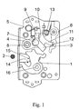
- Fig. 1 shows an inventive locking mechanism in the open position.
- the firing bow 2 is not in engagement with the rotary latch 1.
- the pawl 3 is mounted on the pawl mandrel 7, wherein the pawl mandrel 7 is positioned on the pawl lever 4.
- the pawl lever 4 is pivotally mounted on a mandrel 8.
- the force of the pawl spring 5 engages the lever arm 9 of the pawl 3 and is transmitted to the lever arm 10 of the pawl lever 4. This causes a movement of the pawl lever 4 in a clockwise direction.
- the movement of the pawl lever 4 is stopped via the Blockadehebelarm 11 which abuts against the contour 12 of the locking lever 6.
- a locking lever spring 13 loads the locking lever 6 in the closing direction.
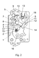
- the striker 2 moves, as in Fig. 2
- the striker 2 presses on the contour 15 of the catch 1, whereby the catch 1 moves to the Dreh fallendom 16 in the closing direction.
- the contour 18 of the rotary latch pivots the pawl 3 on the contour 17 in the counterclockwise direction in the opening direction.
- This is done against the force of the pawl spring 5 is particularly clear in Fig. 2 in that, during the closing operation, only the pawl 3 pivots about the pawl mandrel 7, the pawl lever 4 remaining in its position.
- the pawl 3 falls due to the spring force of the spring 5 back to its original position (see Fig. 3 ). Due to the low mass of the pawl 3 is formed when hitting the pawl lever 4 only a slight noise.
- Fig. 3 the locking mechanism is shown in closed position.
- the rotary latch 1 presses on the pressure contour 23 on the locking contour 19 of the pawl third
- the point of attack on the pawl contour 19, on which the pressure contour 23 of the catch 1 engages and the pivot point 7 is mounted on the pawl 1 are arranged to each other that the lever arm 9 of the pawl 3, the lever arm 10 of the pawl lever 4 charged.
- the locking lever 6 blocked with the contour 12 via the blocking arm 11, the pawl lever 4. Due to this assignment blocks the pawl 3 in conjunction with the pawl lever 4 and the locking lever 6, the movement of the catch 1 in the open position.
- Fig. 4 is the rotary latch 1, the pawl 3, the pawl lever 4 and the locking lever 6 is shown enlarged.
- the direction of the force exerted by the rotary latch 1 on the pawl 3 is shown in this view by the arrow 20.
- the force direction 20 extends between the pivot point 7 of the pawl 3 and the pivot point 8 of the pawl lever 4. This causes the pawl 3, a clockwise torque is generated. Even with vibrations, the pawl 3 always tries to move in the clockwise direction. However, this movement of the pawl 3 is positively locked by the lever arm 10 of the pawl lever 4 and the lever arm 9 of the pawl 3. Thus, a torque in the closing direction is generated on the pawl 3 in the closed position. On the other hand, if a torque is generated counterclockwise, the pawl can escape against the spring force of the pawl spring 5. In this case, a torque is generated in the opening direction.
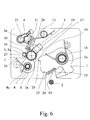
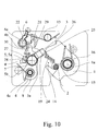
- the Fig. 6 to 10 show a barrier according to the invention in a further embodiment.
- the basic function of the components catch 1, pawl 3, pawl lever 4 and locking lever 6 corresponds to the basic function of the corresponding components in the Fig. 1 to 5 illustrated barrier. Accordingly, it is also in the in the Fig. 6 to 10 Locking mechanism shown around a locking mechanism for a motor vehicle door lock, which is positioned in the assembled state in a motor vehicle door or in a door frame and then holds the motor vehicle door closed or opens in conjunction with a positioned on the door frame or door shooting bracket 2.
- the following is the operation of the in the Fig. 6 to 10 illustrated, the term used in the claims "intermediate lever” again corresponds to the term used in the description "pawl lever".
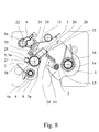
- the barrier is equipped with a rotary latch 1, which is positively connected with the vehicle door closed with the striker 2 ( Fig. 8 ).
- a pawl 3 is provided, which the catch 1 with the vehicle door closed in a pre-locked position, not shown or in Fig. 8 shown blocked main position.
- a pawl lever 4 (intermediate lever 4) and the above pawl 3 form an assembly.
- the direction of the force of the rotary latch 1 on the pawl 3 transmitting force is in Fig. 8 indicated by the reference numeral 20. From this representation shows that it is also in the in the Fig. 6 to 10 illustrated embodiment is such that the rotary latch 1 when the vehicle door is closed, the pawl 3 in the closing direction, in Fig. 8 relative to the pawl lever 4 in the clockwise direction, but charged, but also the assembly of pawl lever 4 and pawl 3 total in the opening direction, in Fig. 8 otherwise counterclockwise, loaded relative to the blocking mechanism.
- the pawl 3 is pivotally mounted on the pawl lever 4 about a pawl axis 3a.
- the pawl lever 4 is pivotally mounted about a pawl lever axis 4a on a fixed part of the motor vehicle door lock, in particular on a housing part of the motor vehicle door lock.
- the catch 1 is in turn mounted pivotably about a rotary latch axis 1a in turn on a fixed part, in particular on a housing part of the motor vehicle door lock.
- a first difference in the Fig. 6 to 10 illustrated embodiment with respect to in the Fig. 1 to 5 illustrated embodiment is that the pawl 3 is coupled relative to the pawl lever 4 with a first spring assembly 5a and that the pawl lever 4 is coupled relative to a fixed part by means of a second spring arrangement 5b.
- the mode of action of the two spring arrangements 5a, 5b will be explained in detail below.
- a locking lever 6 is provided, the pawl lever 4 against movement in the opening direction, in Fig. 8 counterclockwise, blocked.
- the pawl lever 8 is for releasing the locking engagement with the locking lever 6 about a locking lever axis 6a, in Fig. 8 counterclockwise, swiveling.
- the locking lever 6 is closed by the locking lever spring 13 in the closing direction, in Fig. 8 clockwise, biased.
- the pawl 3 on the pawl lever 4 from a sunken position out in which the pawl 3, the catch 1 in the main latching position and in the possibly present pre-locked position ( Fig. 8 ), both in the closing direction (in Fig. 8 clockwise) as well as in the opening direction (in Fig. 8 counterclockwise), here it is pivotable. Any kind of stop the relative movement of the pawl 3 on the pawl lever 4 is therefore not provided.
- the pawl 3 with respect to both directions of movement in a middle position here and preferably in Essentially in the sunken position, biased. The middle position is best described according to Fig. 6 remove.
- the closing process in which in the Fig. 6 to 10 illustrated embodiment corresponds essentially to the closing process in which in the Fig. 1 to 5 illustrated embodiment.
- the striker 2 moves into the inlet mouth 14 of the rotary latch 1, wherein the catch 1 moves around the rotary latch axis 1a in the closing direction.
- the contour 18 of the rotary latch 1 pivots the pawl 3 on the contour 17 in Fig. 6 counterclockwise in the opening direction relative to the pawl lever 4, which takes place against the force of the first spring assembly 5a.
- Fig. 8 shows the state in which the pawl 3 has fallen due to the spring force of the spring assembly 5a in its original position.
- the opening operation which is made up of the sequence of Fig. 8 . 9 and 10 results.
- the main catch 25 and the pre-catch 26 serve to take the main rest position or the pre-locking position by the catch 1, in that the pawl 3 is in blocking engagement with the main catch 25 or the pre-catch 26 when the catch 1 is in the main catch position or in the pre-engaged position.
- rolling motion is to be understood in the present case. This is not only a pure “rolling” of the pawl 3 relative to the catch 1 meant, but also a mixture of rolling and sliding movement between pawl 3 and catch 1. With such a rolling motion can be impulsive noises when canceling the engagement between pawl 3 and Avoid catch 1 as far as possible.
- the spring arrangement 5a is a so-called center-zero spring, which allows a deflection of the pawl 3 out of the middle position in both pivoting directions, in each case against the spring force of the spring arrangement 5a.
- the pawl 3 here and preferably has a driver 27 which is aligned in the middle position to a corresponding driver 28. Both drivers 27, 28 are, as from the Fig. 6 to 10 seen, coupled to the spring assembly 5a.
- the second spring arrangement 5b is used in accordance with the bias of the pawl lever 4 in the closing direction, in Fig. 6 clockwise.
- the opening process is now based on the state of the closed motor vehicle door, in which the locking lever 6, the pawl lever 4 against movement in the opening direction, in Fig. 8 blocked against counterclockwise movement.
- the opening process is triggered by the locking lever 6 in a non-blocking position, in Fig. 8 counterclockwise, in in the Fig. 9 shown position is moved.
- the rotary latch 1 drives the pawl 3 on the pawl lever 4 in the closing direction (in Fig. 9 clockwise).
- the rotary latch 1 drives the pawl lever 4 in the opening direction, in Fig. 9 counterclockwise.
- the locking lever 6 is coupled or coupled to the pawl lever 4 so that the locking lever 6, here and preferably independently of its position, limits the movement of the pawl lever 4 in the closing direction.
- the locking lever 6 and the pawl lever 4 each have an engagement contour 29, 30 which extend here and preferably concentrically to the locking lever axis 6a and which are engaged or engageable with each other for the above coupling.
- this movement limit is guaranteed by a corresponding length of the engagement contours 29, 30 regardless of the position of the locking lever 6.
- an engagement contour 29, 30 is provided exclusively on the locking lever 6 or exclusively on the pawl lever 4. Such a contour would then interact with a corresponding driver o. The like.
- the other lever is coupled or coupled to the pawl lever 4 so that the locking lever 6, here and preferably independently of its position, limits the movement of the pawl lever 4 in the closing direction.
- the locking lever 6 and the pawl lever 4 each have an engagement contour 29, 30 which extend here and preferably concentrically to the locking lever axis 6
- a proposed motor vehicle door lock is claimed as such with a proposed barrier.
Landscapes
- Lock And Its Accessories (AREA)
Applications Claiming Priority (1)
| Application Number | Priority Date | Filing Date | Title |
|---|---|---|---|
| DE201110012651 DE102011012651A1 (de) | 2011-02-28 | 2011-02-28 | Sperrwerk mit Öffnungstendenz |
Publications (3)
| Publication Number | Publication Date |
|---|---|
| EP2492423A2 true EP2492423A2 (fr) | 2012-08-29 |
| EP2492423A3 EP2492423A3 (fr) | 2016-06-01 |
| EP2492423B1 EP2492423B1 (fr) | 2018-12-26 |
Family
ID=45811255
Family Applications (1)
| Application Number | Title | Priority Date | Filing Date |
|---|---|---|---|
| EP12001330.5A Active EP2492423B1 (fr) | 2011-02-28 | 2012-02-28 | Mécanisme de verrouillage doté d'une tendance d'ouverture |
Country Status (2)
| Country | Link |
|---|---|
| EP (1) | EP2492423B1 (fr) |
| DE (1) | DE102011012651A1 (fr) |
Cited By (11)
| Publication number | Priority date | Publication date | Assignee | Title |
|---|---|---|---|---|
| EP2803795A2 (fr) | 2013-05-17 | 2014-11-19 | Brose Schliesssysteme GmbH & Co. KG | Serrure de véhicule automobile |
| WO2014082618A3 (fr) * | 2012-11-28 | 2015-03-19 | Kiekert Aktiengesellschaft | Serrure de porte de véhicule automobile |
| KR20150063478A (ko) * | 2012-09-27 | 2015-06-09 | 키커트 악티엔게젤샤프트 | 셔터 또는 도어용 록 |
| EP2860335A3 (fr) * | 2013-10-08 | 2015-09-30 | Pyeonghwa Automotive Co., Ltd. | Appareil de verrouillage |
| FR3037093A1 (fr) * | 2015-06-05 | 2016-12-09 | Inteva Products Llc | |
| US10113341B2 (en) * | 2013-07-02 | 2018-10-30 | Kiekert Aktiengesellschaft | Motor vehicle lock with a position securing system |
| US20200115930A1 (en) * | 2018-10-11 | 2020-04-16 | Volkswagen Aktiengesellschaft | Method for operating an opening mechanism |
| US20210396054A1 (en) * | 2020-06-19 | 2021-12-23 | Mitsui Kinzoku Act Corporation | Motor-vehicle door latch device |
| US20220186534A1 (en) * | 2019-03-06 | 2022-06-16 | Kiekert Ag | Motor vehicle lock |
| WO2022128553A1 (fr) * | 2020-12-15 | 2022-06-23 | Brose Schliesssysteme Gmbh & Co. Kommanditgesellschaft | Serrure pour véhicule automobile |
| US12398583B2 (en) | 2020-04-04 | 2025-08-26 | Brose Schließsysteme GmbH & Co. Kommanditgesellschaft | Motor vehicle lock |
Families Citing this family (5)
| Publication number | Priority date | Publication date | Assignee | Title |
|---|---|---|---|---|
| DE102020109472A1 (de) | 2020-04-04 | 2021-10-07 | Brose Schließsysteme GmbH & Co. Kommanditgesellschaft | Kraftfahrzeugschloss |
| DE102021101786A1 (de) * | 2021-01-27 | 2022-07-28 | Brose Schließsysteme GmbH & Co. Kommanditgesellschaft | Kraftfahrzeugschloss |
| DE102021102105A1 (de) | 2021-01-29 | 2022-08-04 | Brose Schließsysteme GmbH & Co. Kommanditgesellschaft | Kraftfahrzeugschloss |
| DE102022107452A1 (de) | 2022-03-17 | 2023-09-21 | Brose Schließsysteme GmbH & Co. Kommanditgesellschaft | Kraftfahrzeugschloss |
| DE102022121798A1 (de) | 2022-08-29 | 2024-02-29 | Brose Schließsysteme GmbH & Co. Kommanditgesellschaft | Kraftfahrzeugschloss |
Citations (1)
| Publication number | Priority date | Publication date | Assignee | Title |
|---|---|---|---|---|
| US3386761A (en) | 1965-11-22 | 1968-06-04 | Gen Motors Corp | Vehicle body door latch and locking system |
Family Cites Families (5)
| Publication number | Priority date | Publication date | Assignee | Title |
|---|---|---|---|---|
| IT217128Z2 (it) * | 1989-07-04 | 1991-11-12 | Fiat Auto Spa | Serratura con carico di apertura ridotto |
| DE9116428U1 (de) * | 1991-01-24 | 1992-10-01 | Kiekert GmbH & Co KG, 5628 Heiligenhaus | Kraftfahrzeugtürverschluß |
| DE10214691B4 (de) * | 2002-04-03 | 2013-09-26 | Volkswagen Ag | Verriegelungsvorrichtung |
| DE102007055412A1 (de) * | 2006-12-08 | 2008-06-12 | Kiekert Ag | Geräuscharme Schließvorrichtung für ein Kraftfahrzeug |
| US8596694B2 (en) * | 2008-09-04 | 2013-12-03 | Magna Closures S.P.A. | Vehicle latch with secondary engagement between cam and auxiliary pawl |
-
2011
- 2011-02-28 DE DE201110012651 patent/DE102011012651A1/de not_active Withdrawn
-
2012
- 2012-02-28 EP EP12001330.5A patent/EP2492423B1/fr active Active
Patent Citations (1)
| Publication number | Priority date | Publication date | Assignee | Title |
|---|---|---|---|---|
| US3386761A (en) | 1965-11-22 | 1968-06-04 | Gen Motors Corp | Vehicle body door latch and locking system |
Cited By (18)
| Publication number | Priority date | Publication date | Assignee | Title |
|---|---|---|---|---|
| KR20150063478A (ko) * | 2012-09-27 | 2015-06-09 | 키커트 악티엔게젤샤프트 | 셔터 또는 도어용 록 |
| CN104812980A (zh) * | 2012-09-27 | 2015-07-29 | 开开特股份公司 | 用于罩盖或门的锁 |
| US10294700B2 (en) | 2012-11-28 | 2019-05-21 | Kiekert Aktiengesellschaft | Vehicle door lock |
| WO2014082618A3 (fr) * | 2012-11-28 | 2015-03-19 | Kiekert Aktiengesellschaft | Serrure de porte de véhicule automobile |
| DE102013008415A1 (de) | 2013-05-17 | 2014-11-20 | BROSE SCHLIEßSYSTEME GMBH & CO. KG | Kraftfahrzeugschloss |
| EP2803795A2 (fr) | 2013-05-17 | 2014-11-19 | Brose Schliesssysteme GmbH & Co. KG | Serrure de véhicule automobile |
| US10113341B2 (en) * | 2013-07-02 | 2018-10-30 | Kiekert Aktiengesellschaft | Motor vehicle lock with a position securing system |
| EP2860335A3 (fr) * | 2013-10-08 | 2015-09-30 | Pyeonghwa Automotive Co., Ltd. | Appareil de verrouillage |
| FR3037093A1 (fr) * | 2015-06-05 | 2016-12-09 | Inteva Products Llc | |
| US20200115930A1 (en) * | 2018-10-11 | 2020-04-16 | Volkswagen Aktiengesellschaft | Method for operating an opening mechanism |
| US11725427B2 (en) * | 2018-10-11 | 2023-08-15 | Volkswagen Aktiengesellschaft | Method for operating an opening mechanism |
| US20220186534A1 (en) * | 2019-03-06 | 2022-06-16 | Kiekert Ag | Motor vehicle lock |
| US11970888B2 (en) * | 2019-03-06 | 2024-04-30 | Kiekert Ag | Motor vehicle lock |
| US12398583B2 (en) | 2020-04-04 | 2025-08-26 | Brose Schließsysteme GmbH & Co. Kommanditgesellschaft | Motor vehicle lock |
| US20210396054A1 (en) * | 2020-06-19 | 2021-12-23 | Mitsui Kinzoku Act Corporation | Motor-vehicle door latch device |
| US11965367B2 (en) * | 2020-06-19 | 2024-04-23 | Mitsui Kinzoku Act Corporation | Motor-vehicle door latch device |
| WO2022128553A1 (fr) * | 2020-12-15 | 2022-06-23 | Brose Schliesssysteme Gmbh & Co. Kommanditgesellschaft | Serrure pour véhicule automobile |
| CN117280107A (zh) * | 2020-12-15 | 2023-12-22 | 博泽车锁系统有限公司 | 机动车锁 |
Also Published As
| Publication number | Publication date |
|---|---|
| EP2492423B1 (fr) | 2018-12-26 |
| DE102011012651A1 (de) | 2012-08-30 |
| EP2492423A3 (fr) | 2016-06-01 |
Similar Documents
| Publication | Publication Date | Title |
|---|---|---|
| EP2492423B1 (fr) | Mécanisme de verrouillage doté d'une tendance d'ouverture | |
| DE102017108265A1 (de) | Schloss für ein Kraftfahrzeug | |
| DE102017214021A1 (de) | Fahrzeug-Verriegelungsanordnung mit Verriegelungsmechanismus mit Entlastungsgeräuschreduktion | |
| DE102015112500A1 (de) | Kraftfahrzeugschloss | |
| DE102021102105A1 (de) | Kraftfahrzeugschloss | |
| EP3173554A1 (fr) | Serrure de véhicule automobile | |
| WO2009121864A1 (fr) | Verrouillage pour porte pivotante extérieure | |
| WO2023110023A1 (fr) | Ensemble porte de véhicule automobile | |
| DE19616655A1 (de) | Vorrichtung zum Öffnen und Schließen einer Tür oder Klappe | |
| EP2987931B1 (fr) | Serrure de véhicule automobile | |
| DE102013207725A1 (de) | Kraftfahrzeugschloss | |
| EP2257441A1 (fr) | Porte de véhicule automobile | |
| DE102017101703A1 (de) | Schloss mit Zuzieheinrichtung für ein Kraftfahrzeug | |
| EP4015745A1 (fr) | Dispositif de fermeture | |
| EP2670934B1 (fr) | Serrure de véhicule à moteur | |
| EP3870785B1 (fr) | Serrure de véhicule automobile, en particulier serrure de porte de véhicule automobile | |
| EP3679208A1 (fr) | Serrure de porte de véhicule automobile | |
| EP3559382B1 (fr) | Serrure, en particulier pour dossier ou hayon | |
| EP3867473B1 (fr) | Serrure de véhicule automobile | |
| EP3385482B1 (fr) | Dispositif de verrouillage pour un véhicule | |
| WO2016206666A1 (fr) | Serrure de véhicule automobile | |
| DE102018102628A1 (de) | Kraftfahrzeugschloss | |
| DE102007061442B4 (de) | Verriegelungsvorrichtung mit kraftbetätigtem Schließelement | |
| WO2018108803A1 (fr) | Serrure, en particulier serrure de hayon | |
| DE102023117308A1 (de) | Kraftfahrzeug-Schloss |
Legal Events
| Date | Code | Title | Description |
|---|---|---|---|
| PUAI | Public reference made under article 153(3) epc to a published international application that has entered the european phase |
Free format text: ORIGINAL CODE: 0009012 |
|
| AK | Designated contracting states |
Kind code of ref document: A2 Designated state(s): AL AT BE BG CH CY CZ DE DK EE ES FI FR GB GR HR HU IE IS IT LI LT LU LV MC MK MT NL NO PL PT RO RS SE SI SK SM TR |
|
| AX | Request for extension of the european patent |
Extension state: BA ME |
|
| RIN1 | Information on inventor provided before grant (corrected) |
Inventor name: EL-HAMOUMI, ABDELALI Inventor name: REINERT, JOERG Inventor name: SCHMIDT, TATJANA Inventor name: KOTHE, MARKUS |
|
| RIN1 | Information on inventor provided before grant (corrected) |
Inventor name: EL-HAMOUMI, ABDELALI Inventor name: SCHMIDT, TATJANA Inventor name: REINERT, JOERG Inventor name: KOTHE, MARKUS |
|
| PUAL | Search report despatched |
Free format text: ORIGINAL CODE: 0009013 |
|
| AK | Designated contracting states |
Kind code of ref document: A3 Designated state(s): AL AT BE BG CH CY CZ DE DK EE ES FI FR GB GR HR HU IE IS IT LI LT LU LV MC MK MT NL NO PL PT RO RS SE SI SK SM TR |
|
| AX | Request for extension of the european patent |
Extension state: BA ME |
|
| RIC1 | Information provided on ipc code assigned before grant |
Ipc: E05B 15/04 20060101ALN20160422BHEP Ipc: E05B 65/32 00000000AFI20160422BHEP |
|
| STAA | Information on the status of an ep patent application or granted ep patent |
Free format text: STATUS: REQUEST FOR EXAMINATION WAS MADE |
|
| 17P | Request for examination filed |
Effective date: 20161201 |
|
| RBV | Designated contracting states (corrected) |
Designated state(s): AL AT BE BG CH CY CZ DE DK EE ES FI FR GB GR HR HU IE IS IT LI LT LU LV MC MK MT NL NO PL PT RO RS SE SI SK SM TR |
|
| REG | Reference to a national code |
Ref country code: DE Ref legal event code: R079 Ref document number: 502012014028 Country of ref document: DE Free format text: PREVIOUS MAIN CLASS: E05B0065320000 Ipc: E05B0077360000 |
|
| GRAP | Despatch of communication of intention to grant a patent |
Free format text: ORIGINAL CODE: EPIDOSNIGR1 |
|
| STAA | Information on the status of an ep patent application or granted ep patent |
Free format text: STATUS: GRANT OF PATENT IS INTENDED |
|
| RIC1 | Information provided on ipc code assigned before grant |
Ipc: E05B 15/04 20060101ALN20180628BHEP Ipc: E05B 77/36 20140101AFI20180628BHEP Ipc: E05B 85/26 20140101ALI20180628BHEP |
|
| INTG | Intention to grant announced |
Effective date: 20180712 |
|
| RIC1 | Information provided on ipc code assigned before grant |
Ipc: E05B 77/36 20140101AFI20180703BHEP Ipc: E05B 15/04 20060101ALN20180703BHEP Ipc: E05B 85/26 20140101ALI20180703BHEP |
|
| GRAS | Grant fee paid |
Free format text: ORIGINAL CODE: EPIDOSNIGR3 |
|
| GRAA | (expected) grant |
Free format text: ORIGINAL CODE: 0009210 |
|
| STAA | Information on the status of an ep patent application or granted ep patent |
Free format text: STATUS: THE PATENT HAS BEEN GRANTED |
|
| AK | Designated contracting states |
Kind code of ref document: B1 Designated state(s): AL AT BE BG CH CY CZ DE DK EE ES FI FR GB GR HR HU IE IS IT LI LT LU LV MC MK MT NL NO PL PT RO RS SE SI SK SM TR |
|
| REG | Reference to a national code |
Ref country code: GB Ref legal event code: FG4D Free format text: NOT ENGLISH |
|
| REG | Reference to a national code |
Ref country code: CH Ref legal event code: EP |
|
| REG | Reference to a national code |
Ref country code: AT Ref legal event code: REF Ref document number: 1081638 Country of ref document: AT Kind code of ref document: T Effective date: 20190115 |
|
| REG | Reference to a national code |
Ref country code: DE Ref legal event code: R096 Ref document number: 502012014028 Country of ref document: DE |
|
| REG | Reference to a national code |
Ref country code: IE Ref legal event code: FG4D Free format text: LANGUAGE OF EP DOCUMENT: GERMAN |
|
| PG25 | Lapsed in a contracting state [announced via postgrant information from national office to epo] |
Ref country code: FI Free format text: LAPSE BECAUSE OF FAILURE TO SUBMIT A TRANSLATION OF THE DESCRIPTION OR TO PAY THE FEE WITHIN THE PRESCRIBED TIME-LIMIT Effective date: 20181226 Ref country code: BG Free format text: LAPSE BECAUSE OF FAILURE TO SUBMIT A TRANSLATION OF THE DESCRIPTION OR TO PAY THE FEE WITHIN THE PRESCRIBED TIME-LIMIT Effective date: 20190326 Ref country code: LT Free format text: LAPSE BECAUSE OF FAILURE TO SUBMIT A TRANSLATION OF THE DESCRIPTION OR TO PAY THE FEE WITHIN THE PRESCRIBED TIME-LIMIT Effective date: 20181226 Ref country code: HR Free format text: LAPSE BECAUSE OF FAILURE TO SUBMIT A TRANSLATION OF THE DESCRIPTION OR TO PAY THE FEE WITHIN THE PRESCRIBED TIME-LIMIT Effective date: 20181226 Ref country code: LV Free format text: LAPSE BECAUSE OF FAILURE TO SUBMIT A TRANSLATION OF THE DESCRIPTION OR TO PAY THE FEE WITHIN THE PRESCRIBED TIME-LIMIT Effective date: 20181226 Ref country code: NO Free format text: LAPSE BECAUSE OF FAILURE TO SUBMIT A TRANSLATION OF THE DESCRIPTION OR TO PAY THE FEE WITHIN THE PRESCRIBED TIME-LIMIT Effective date: 20190326 |
|
| REG | Reference to a national code |
Ref country code: NL Ref legal event code: MP Effective date: 20181226 |
|
| REG | Reference to a national code |
Ref country code: LT Ref legal event code: MG4D |
|
| PG25 | Lapsed in a contracting state [announced via postgrant information from national office to epo] |
Ref country code: GR Free format text: LAPSE BECAUSE OF FAILURE TO SUBMIT A TRANSLATION OF THE DESCRIPTION OR TO PAY THE FEE WITHIN THE PRESCRIBED TIME-LIMIT Effective date: 20190327 Ref country code: RS Free format text: LAPSE BECAUSE OF FAILURE TO SUBMIT A TRANSLATION OF THE DESCRIPTION OR TO PAY THE FEE WITHIN THE PRESCRIBED TIME-LIMIT Effective date: 20181226 Ref country code: AL Free format text: LAPSE BECAUSE OF FAILURE TO SUBMIT A TRANSLATION OF THE DESCRIPTION OR TO PAY THE FEE WITHIN THE PRESCRIBED TIME-LIMIT Effective date: 20181226 Ref country code: SE Free format text: LAPSE BECAUSE OF FAILURE TO SUBMIT A TRANSLATION OF THE DESCRIPTION OR TO PAY THE FEE WITHIN THE PRESCRIBED TIME-LIMIT Effective date: 20181226 |
|
| PG25 | Lapsed in a contracting state [announced via postgrant information from national office to epo] |
Ref country code: NL Free format text: LAPSE BECAUSE OF FAILURE TO SUBMIT A TRANSLATION OF THE DESCRIPTION OR TO PAY THE FEE WITHIN THE PRESCRIBED TIME-LIMIT Effective date: 20181226 |
|
| PG25 | Lapsed in a contracting state [announced via postgrant information from national office to epo] |
Ref country code: IT Free format text: LAPSE BECAUSE OF FAILURE TO SUBMIT A TRANSLATION OF THE DESCRIPTION OR TO PAY THE FEE WITHIN THE PRESCRIBED TIME-LIMIT Effective date: 20181226 Ref country code: PT Free format text: LAPSE BECAUSE OF FAILURE TO SUBMIT A TRANSLATION OF THE DESCRIPTION OR TO PAY THE FEE WITHIN THE PRESCRIBED TIME-LIMIT Effective date: 20190426 Ref country code: ES Free format text: LAPSE BECAUSE OF FAILURE TO SUBMIT A TRANSLATION OF THE DESCRIPTION OR TO PAY THE FEE WITHIN THE PRESCRIBED TIME-LIMIT Effective date: 20181226 Ref country code: PL Free format text: LAPSE BECAUSE OF FAILURE TO SUBMIT A TRANSLATION OF THE DESCRIPTION OR TO PAY THE FEE WITHIN THE PRESCRIBED TIME-LIMIT Effective date: 20181226 |
|
| PG25 | Lapsed in a contracting state [announced via postgrant information from national office to epo] |
Ref country code: SK Free format text: LAPSE BECAUSE OF FAILURE TO SUBMIT A TRANSLATION OF THE DESCRIPTION OR TO PAY THE FEE WITHIN THE PRESCRIBED TIME-LIMIT Effective date: 20181226 Ref country code: RO Free format text: LAPSE BECAUSE OF FAILURE TO SUBMIT A TRANSLATION OF THE DESCRIPTION OR TO PAY THE FEE WITHIN THE PRESCRIBED TIME-LIMIT Effective date: 20181226 Ref country code: SM Free format text: LAPSE BECAUSE OF FAILURE TO SUBMIT A TRANSLATION OF THE DESCRIPTION OR TO PAY THE FEE WITHIN THE PRESCRIBED TIME-LIMIT Effective date: 20181226 Ref country code: EE Free format text: LAPSE BECAUSE OF FAILURE TO SUBMIT A TRANSLATION OF THE DESCRIPTION OR TO PAY THE FEE WITHIN THE PRESCRIBED TIME-LIMIT Effective date: 20181226 Ref country code: IS Free format text: LAPSE BECAUSE OF FAILURE TO SUBMIT A TRANSLATION OF THE DESCRIPTION OR TO PAY THE FEE WITHIN THE PRESCRIBED TIME-LIMIT Effective date: 20190426 |
|
| REG | Reference to a national code |
Ref country code: DE Ref legal event code: R097 Ref document number: 502012014028 Country of ref document: DE |
|
| REG | Reference to a national code |
Ref country code: CH Ref legal event code: PL |
|
| PG25 | Lapsed in a contracting state [announced via postgrant information from national office to epo] |
Ref country code: DK Free format text: LAPSE BECAUSE OF FAILURE TO SUBMIT A TRANSLATION OF THE DESCRIPTION OR TO PAY THE FEE WITHIN THE PRESCRIBED TIME-LIMIT Effective date: 20181226 Ref country code: LU Free format text: LAPSE BECAUSE OF NON-PAYMENT OF DUE FEES Effective date: 20190228 Ref country code: MC Free format text: LAPSE BECAUSE OF FAILURE TO SUBMIT A TRANSLATION OF THE DESCRIPTION OR TO PAY THE FEE WITHIN THE PRESCRIBED TIME-LIMIT Effective date: 20181226 |
|
| PLBE | No opposition filed within time limit |
Free format text: ORIGINAL CODE: 0009261 |
|
| STAA | Information on the status of an ep patent application or granted ep patent |
Free format text: STATUS: NO OPPOSITION FILED WITHIN TIME LIMIT |
|
| REG | Reference to a national code |
Ref country code: BE Ref legal event code: MM Effective date: 20190228 |
|
| REG | Reference to a national code |
Ref country code: IE Ref legal event code: MM4A |
|
| 26N | No opposition filed |
Effective date: 20190927 |
|
| PG25 | Lapsed in a contracting state [announced via postgrant information from national office to epo] |
Ref country code: CH Free format text: LAPSE BECAUSE OF NON-PAYMENT OF DUE FEES Effective date: 20190228 Ref country code: LI Free format text: LAPSE BECAUSE OF NON-PAYMENT OF DUE FEES Effective date: 20190228 |
|
| PG25 | Lapsed in a contracting state [announced via postgrant information from national office to epo] |
Ref country code: IE Free format text: LAPSE BECAUSE OF NON-PAYMENT OF DUE FEES Effective date: 20190228 |
|
| PG25 | Lapsed in a contracting state [announced via postgrant information from national office to epo] |
Ref country code: SI Free format text: LAPSE BECAUSE OF FAILURE TO SUBMIT A TRANSLATION OF THE DESCRIPTION OR TO PAY THE FEE WITHIN THE PRESCRIBED TIME-LIMIT Effective date: 20181226 Ref country code: BE Free format text: LAPSE BECAUSE OF NON-PAYMENT OF DUE FEES Effective date: 20190228 |
|
| PG25 | Lapsed in a contracting state [announced via postgrant information from national office to epo] |
Ref country code: TR Free format text: LAPSE BECAUSE OF FAILURE TO SUBMIT A TRANSLATION OF THE DESCRIPTION OR TO PAY THE FEE WITHIN THE PRESCRIBED TIME-LIMIT Effective date: 20181226 |
|
| REG | Reference to a national code |
Ref country code: AT Ref legal event code: MM01 Ref document number: 1081638 Country of ref document: AT Kind code of ref document: T Effective date: 20190228 |
|
| PG25 | Lapsed in a contracting state [announced via postgrant information from national office to epo] |
Ref country code: AT Free format text: LAPSE BECAUSE OF NON-PAYMENT OF DUE FEES Effective date: 20190228 |
|
| PG25 | Lapsed in a contracting state [announced via postgrant information from national office to epo] |
Ref country code: MT Free format text: LAPSE BECAUSE OF FAILURE TO SUBMIT A TRANSLATION OF THE DESCRIPTION OR TO PAY THE FEE WITHIN THE PRESCRIBED TIME-LIMIT Effective date: 20181226 |
|
| PG25 | Lapsed in a contracting state [announced via postgrant information from national office to epo] |
Ref country code: CY Free format text: LAPSE BECAUSE OF FAILURE TO SUBMIT A TRANSLATION OF THE DESCRIPTION OR TO PAY THE FEE WITHIN THE PRESCRIBED TIME-LIMIT Effective date: 20181226 |
|
| PG25 | Lapsed in a contracting state [announced via postgrant information from national office to epo] |
Ref country code: HU Free format text: LAPSE BECAUSE OF FAILURE TO SUBMIT A TRANSLATION OF THE DESCRIPTION OR TO PAY THE FEE WITHIN THE PRESCRIBED TIME-LIMIT; INVALID AB INITIO Effective date: 20120228 |
|
| PG25 | Lapsed in a contracting state [announced via postgrant information from national office to epo] |
Ref country code: MK Free format text: LAPSE BECAUSE OF FAILURE TO SUBMIT A TRANSLATION OF THE DESCRIPTION OR TO PAY THE FEE WITHIN THE PRESCRIBED TIME-LIMIT Effective date: 20181226 |
|
| P01 | Opt-out of the competence of the unified patent court (upc) registered |
Effective date: 20230803 |
|
| PGFP | Annual fee paid to national office [announced via postgrant information from national office to epo] |
Ref country code: FR Payment date: 20241231 Year of fee payment: 14 |
|
| PGFP | Annual fee paid to national office [announced via postgrant information from national office to epo] |
Ref country code: CZ Payment date: 20250218 Year of fee payment: 14 |
|
| PGFP | Annual fee paid to national office [announced via postgrant information from national office to epo] |
Ref country code: GB Payment date: 20250102 Year of fee payment: 14 |
|
| PGFP | Annual fee paid to national office [announced via postgrant information from national office to epo] |
Ref country code: DE Payment date: 20260228 Year of fee payment: 15 |