EP2492123A1 - Window element for a side door, in particular a rear side door of a motor vehicle - Google Patents
Window element for a side door, in particular a rear side door of a motor vehicle Download PDFInfo
- Publication number
- EP2492123A1 EP2492123A1 EP12156299A EP12156299A EP2492123A1 EP 2492123 A1 EP2492123 A1 EP 2492123A1 EP 12156299 A EP12156299 A EP 12156299A EP 12156299 A EP12156299 A EP 12156299A EP 2492123 A1 EP2492123 A1 EP 2492123A1
- Authority
- EP
- European Patent Office
- Prior art keywords
- window
- plastic
- side door
- frame
- portal
- Prior art date
- Legal status (The legal status is an assumption and is not a legal conclusion. Google has not performed a legal analysis and makes no representation as to the accuracy of the status listed.)
- Granted
Links
Images


Classifications
-
- B—PERFORMING OPERATIONS; TRANSPORTING
- B60—VEHICLES IN GENERAL
- B60J—WINDOWS, WINDSCREENS, NON-FIXED ROOFS, DOORS, OR SIMILAR DEVICES FOR VEHICLES; REMOVABLE EXTERNAL PROTECTIVE COVERINGS SPECIALLY ADAPTED FOR VEHICLES
- B60J1/00—Windows; Windscreens; Accessories therefor
- B60J1/004—Mounting of windows
- B60J1/006—Mounting of windows characterised by fixation means such as clips, adhesive, etc.
-
- B—PERFORMING OPERATIONS; TRANSPORTING
- B60—VEHICLES IN GENERAL
- B60J—WINDOWS, WINDSCREENS, NON-FIXED ROOFS, DOORS, OR SIMILAR DEVICES FOR VEHICLES; REMOVABLE EXTERNAL PROTECTIVE COVERINGS SPECIALLY ADAPTED FOR VEHICLES
- B60J10/00—Sealing arrangements
- B60J10/20—Sealing arrangements characterised by the shape
- B60J10/26—Sealing arrangements characterised by the shape characterised by the surface shape
- B60J10/265—Sealing arrangements characterised by the shape characterised by the surface shape the surface being primarily decorative
-
- B—PERFORMING OPERATIONS; TRANSPORTING
- B60—VEHICLES IN GENERAL
- B60J—WINDOWS, WINDSCREENS, NON-FIXED ROOFS, DOORS, OR SIMILAR DEVICES FOR VEHICLES; REMOVABLE EXTERNAL PROTECTIVE COVERINGS SPECIALLY ADAPTED FOR VEHICLES
- B60J10/00—Sealing arrangements
- B60J10/70—Sealing arrangements specially adapted for windows or windscreens
- B60J10/74—Sealing arrangements specially adapted for windows or windscreens for sliding window panes, e.g. sash guides
Definitions
- the invention relates to a window element for a side door, in particular a rear side door, of a motor vehicle according to claim 1.
- side doors in particular of combi vehicles, have a first window portal and a second window portal adjoining thereto.
- a frame member is attached to a shell of the side door.
- a side window associated with one of the window portals is fixed to the shell, which is immovable relative to the shell.
- cover elements are provided, which cover frame parts of the frame member and / or vehicle pillars of the body of the motor vehicle at least partially, to make the visual impression of the side door positive.
- the side window, the cover and possibly other component may lead to tolerances, the compensation of a time-consuming and therefore costly installation conditions and possibly only very difficult.
- a window element according to the invention for a side door, in particular a rear side door, of a motor vehicle, in particular a passenger car comprises at least one frame element having a guide, through which a first window portal and an adjoining further window portal of the side door are at least partially limited.
- the frame member is a side window between the first window portal occlusive and at least one first window portal at least partially releasing position along the guide feasible.
- the window element according to the invention further comprises a window web, by means of which a frame part of the frame element, which separates the first and the further window gantry spatially, in particular in the vehicle longitudinal direction, is at least partially covered.
- the window element according to the invention comprises a side pane held firmly on the frame element, by means of which the further window portal is covered.
- the side window held on the frame element is at least partially provided with at least one plastic, in particular encapsulated, via which a screw with the window web and / or with a Mosrohbau the door can be formed.
- the side window held on the frame element is, for example, in an edge area with the at least one plastic, in particular by an injection molding, encapsulated.
- At least one fastening means and / or at least one corresponding functional structure is formed by the plastic, via which the window web and optionally a cover of a vehicle pillar, in particular a B-pillar or a C-pillar, associated cover member is attached to the frame member.
- This fastening means or the functional structure can be, for example, at least one clip element, by means of which the window web and / or the cover element is clipped to the frame element via the at least one plastic.
- this clipping the window web and / or the cover is locked to the frame member, said locking in a simple, time and thus cost-effective manner is feasible.
- the window element has a simplified and thus more time and less expensive installation. Additional and time-consuming and therefore costly assembly operations for tolerance compensation are not provided and not required.
- the avoidance of the positional tolerances is in particular given by the fact that connection geometries or the representation of the screwing and the fastenability of a tool are, that are made by means of one and the same tool by the plastic.
- the window element according to the invention also has a particularly low number of parts and thus a very small number of assembly operations, which keeps the installation costs and thus the total cost of the window element and thus the entire motor vehicle low.
- the side pane held on the frame element is provided with the at least one plastic and with at least one further plastic, in particular at least partially encapsulated.
- the further plastic is softer than the first, at least one plastic formed. Due to the harder of plastics, the described Verschraubhus the plastic and thus the frame member with the window web and / or with the Matrohbau and optionally the fastening means for fixing the window web on the frame element is formed. Due to the softer of the plastics a sealing function is preferably shown, whereby the frame element is sealed to the door shell and / or other components, in particular sheet metal components, the side door.
- the cover element and / or the window web are formed by a so-called two-component encapsulation of the side window held on the frame element.
- the side window held on the frame member is provided with a two-component plastic, through which the cover and the window bar and the described Verschraubbarkeit and optionally the fastening means are formed. This keeps the number of parts of the window element low.
- the training in particular of the cover as a separate item has the advantage that they cover as theft protection screwing of the frame member with the door shell and can provide a visually positive impression of the side door.
- At least the side window, the window web and the frame element held on the frame element are combined to form a modular component.
- this module component an addition of tolerances is avoided, especially in the vehicle longitudinal direction. Furthermore, this module component allows a particularly simple and thus time and cost assembly.
- the summary of the frame part, the window web and the frame member held on the side window to the module component also makes it possible to produce the module component at least substantially parallel to the production of the side door and pre-assembled and then deliver in the pre-assembled state as assembly, for example, to a production line of the motor vehicle. Then, the module component can be assembled as an assembly on the side door, in particular the door shell, time and cost. This summary of the module component time-consuming and costly assembly operations to compensate for tolerances are not provided and not required.
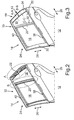
- the Fig. 1 shows a window element 10 for a side door 12 (FIG. Fig. 2 ) for a trained as a combined vehicle passenger cars.
- the side door 12 is a rear door in the vehicle longitudinal direction, which is referred to as a rear door and is arranged in the vehicle longitudinal direction behind a front door.
- the window element 10 comprises a frame element 14, by means of which a first window portal 16 and a window portal 18 adjoining the window portal 16 in the vehicle longitudinal direction according to a directional arrow 29 are partially delimited.
- the frame element 14 has a frame part 20 through which the window portals 16 and 18 in the vehicle longitudinal direction according to the directional arrow 29 are spatially separated from each other.
- the frame member 14 comprises a triangular disc 22 through which the window portal 18 is covered and which is held firmly on the frame member 14.
- the triangular disk 22 is a fixed side window, which is immovable relative to the frame element 14 and overall to the side door 12.
- the frame member 14 also includes a so-called window track 24 which provides guidance.
- the guide is used to guide the window portal 16 associated side window along the guide of the window rail 24 between a Window portal 16 at least partially releasing and at least one window portal 16 on the other hand closing position in the vehicle vertical direction according to a direction arrow 26 is movable.
- the panel 30 is associated with a B pillar of the body of the passenger car and serves to cover the B pillar at least partially.
- the panel 30 is mounted on the B-pillar, aligned and fastened with three screws on the shell of the body, followed by the assembly of the window member 10 is connected.
- the window element 10 furthermore comprises a window web 32 which at least partially covers the frame part 20 and which is fastened to the frame element 14 by clipping the window web 32 to the frame element 14. There is no alignment.
- the window element 10 comprises a panel 34, which is clipped with the mounted frame member 14. Again, there is no further alignment.
- the panel 34 is assigned to a C-pillar of the body of the passenger car and serves to at least partially cover the C-pillar and a frame part 36 of the frame member 14 and so provide a visually good impression of the frame member 14.
- the Fig. 1 gives an overview of individual parts above a curb 38 ( Fig. 2 ), in particular for guiding the window portal 16 associated side window.
- FIGS. 2 and 3 illustrate the described assembly process of the window member 10 and the panel 30.
- the frame member 14 is preassembled with the window rail 24 and the triangular disk 22, wherein in particular the window rail 24 is aligned with a panel 40.
- the window rail 24 is assembled at the top.
- the triangle disc 22 is attached to the window web 32 with three screws in corresponding slots, with no alignment takes place.
- the triangular disk 22 is fastened at the rear with two screws via corresponding elongated holes on the door frame 28, wherein likewise no alignment takes place.
- the aperture 30 is fixed with three screws and no alignment is performed.
- the window bar 32 is clipped.
- the panel 34 is clipped to the frame member 14.
- the Fig. 4 shows the side door 12 according to Fig. 2 in a marked area A.
- the triangular disc 22 is encapsulated in edge regions of the triangular disc 22 with a first plastic 46.
- screw 48 are formed, which may be, for example, Anschraubdome with an internal thread or openings.
- the triangular disc 22 can be screwed to the door shell 28 from the outside, whereby the frame member 14 can be screwed to the door shell 28.
- clip elements 50 are formed by the plastic 46, by means of which the rear panel 34 can be clipped and guided.
- the Fig. 5 shows the side door 12 according to Fig. 2 in a marked area B. Also in the area B, the triangular disk 22 is encapsulated in marginal areas with the plastic 46. By means of the plastic 46, screw means 52 are also formed in the region B, by means of which the window web 32 can be screwed to the frame element 14.
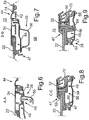
- the 6 and 9 show the encapsulation of the triangular disc 22 with the plastic 46 and with another plastic 47, with which the triangular disc 22 is also provided.
- the plastic 46th harder than the plastic 47th are formed by the harder plastic 46, the screw means 48 and the clip elements 50, so that the plastic 46 and on this the triangular disc 22 can be particularly firmly attached to the door shell 28.
- the door shell 28 comprises a first sheet metal component 54 and a connected thereto, for example, welded, another sheet metal component 56th
- a screw 58 can be seen, by means of which the plastic 46 is bolted to the door shell 28 via the screw means 48 designed as a passage opening.
- the C-pillar associated rear panel 34 is clipped over the hard or harder plastic 46 to the frame member 14.
- a sealing function whereby the frame member 14 and the triangular disc 22 is sealed against the Schorohbau 28.
- a sealing lip 60 is formed by the softer plastic 47, which bears against the sheet-metal component 54.
- the harder plastic 46 is used, in particular the Fig. 8 can also be seen, to attach the window bar 32 to the frame member 14 by the window bar 32 is clipped with the harder plastic 46.
- the softer plastic 47 By the softer plastic 47, a further sealing lip 62 is formed, which rests against the window web 32 and on the triangular disc 22, and fulfills a sealing function.
- the Fig. 9 shows a Anschraubdom 64 formed by the harder plastic 46 of the screw 48, which has an internal thread.
- a screw 66 is screwed into the screw-on dome 64, so that the triangular disk 22 can be fastened to the door frame 28 or to the sheet metal component 54 via the screw-on dome 64 from an inner side 68 of the side door 12 and thus of the passenger car.
- an outside 70 of the side door 12 or of the passenger car can be seen.
- the joint lip 44 on the panel 34 is held.
- the joint lip 44 forms a Hägreifung with the diaphragm 34 and is clipped with this.
- the harder plastic 46 also serves to hold a sealing and guiding element 72 through which the window portal 16 associated side window is guided and sealed. Thus, moisture can not penetrate from the outside 70 to the inside 68 and thus into an interior of the passenger car.
- the directional arrow 42 is shown, which indicates the tolerance compensation by the C-pillar associated Fugenlippe 44.
- the tolerance compensation is performed by moving on a sealing surface 74 of a rear side disk 76 according to the directional arrow 42.
- one of the clip elements 50 can be seen, which is represented by the harder plastic 46 and over which the window bar 32 is clipped to the frame element 14.
Abstract
Description
Die Erfindung betrifft ein Fensterelement für eine Seitentür, insbesondere eine hintere Seitentür, eines Kraftwagens gemäß Patentanspruch 1.The invention relates to a window element for a side door, in particular a rear side door, of a motor vehicle according to
Aus dem Serienbau von Kraftwagen ist es bekannt, dass Seitentüren insbesondere von Kombifahrzeugen ein erstes Fensterportal sowie ein sich daran anschließendes zweites Fensterportal aufweisen. Um die Fensterportale mit einer jeweiligen Seitenscheibe versehen zu können, wird ein Rahmenelement an einem Rohbau der Seitentür befestigt. Ferner wird an dem Rohbau eine einem der Fensterportale zugeordnete Seitenscheibe befestigt, welche relativ zu dem Rohbau unbeweglich ist. Darüber hinaus sind Abdeckelemente vorgesehen, welche Rahmenteile des Rahmenelements und/oder Fahrzeugsäulen der Karosserie des Kraftwagens zumindest bereichsweise abdecken, um den optischen Eindruck der Seitentür positiv zu gestalten. Bei der Befestigung und der Montage des Rahmenelements, der Seitenscheibe, der Abdeckelemente sowie gegebenenfalls weiterer Bauteil kann es zu Toleranzen kommen, deren Kompensation eine zeit- und damit kostenaufwändige Montage bedingt sowie gegebenenfalls nur sehr schwer möglich ist.From the serial production of motor vehicles, it is known that side doors, in particular of combi vehicles, have a first window portal and a second window portal adjoining thereto. In order to provide the window portals with a respective side window, a frame member is attached to a shell of the side door. Further, a side window associated with one of the window portals is fixed to the shell, which is immovable relative to the shell. In addition, cover elements are provided, which cover frame parts of the frame member and / or vehicle pillars of the body of the motor vehicle at least partially, to make the visual impression of the side door positive. In the attachment and assembly of the frame member, the side window, the cover and possibly other component may lead to tolerances, the compensation of a time-consuming and therefore costly installation conditions and possibly only very difficult.
Es ist daher Aufgabe der vorliegenden Erfindung, ein Fensterelement für eine Seitentür, insbesondere eine hintere Seitentür, eines Kraftwagens bereitzustellen, welches eine vereinfachte Montage aufweist.It is therefore an object of the present invention to provide a window element for a side door, in particular a rear side door, of a motor vehicle, which has a simplified assembly.
Diese Aufgabe wird durch ein Fensterelement für eine Seitentür, insbesondere eine hintere Seitentür, eines Kraftwagens mit den Merkmalen des Patentanspruchs 1 gelöst. Vorteilhafte Ausgestaltungen mit zweckmäßigen und nicht-trivialen Weiterbildungen der Erfindung sind in den übrigen Ansprüchen angegeben.This object is achieved by a window element for a side door, in particular a rear side door, a motor vehicle with the features of
Ein erfindungsgemäßes Fensterelement für eine Seitentür, insbesondere eine hintere Seitentür, eines Kraftwagens, insbesondere eines Personenkraftwagens, umfasst wenigstens ein eine Führung aufweisendes Rahmenelement, durch welches ein erstes Fensterportal sowie ein sich daran anschließendes weiteres Fensterportal der Seitentür zumindest bereichsweise begrenzt sind. Mittels des Rahmenelements ist eine Seitenscheibe zwischen einer das erste Fensterportal verschließenden und wenigstens einer das erste Fensterportal zumindest bereichsweise freigebenden Stellung entlang der Führung führbar. Das erfindungsgemäße Fensterelement umfasst ferner einen Fenstersteg, mittels welchem ein das erste und das weitere Fensterportal räumlich, insbesondere in Fahrzeuglängsrichtung, voneinander trennendes Rahmenteil des Rahmenelements zumindest bereichsweise abgedeckt ist.A window element according to the invention for a side door, in particular a rear side door, of a motor vehicle, in particular a passenger car, comprises at least one frame element having a guide, through which a first window portal and an adjoining further window portal of the side door are at least partially limited. By means of the frame member is a side window between the first window portal occlusive and at least one first window portal at least partially releasing position along the guide feasible. The window element according to the invention further comprises a window web, by means of which a frame part of the frame element, which separates the first and the further window gantry spatially, in particular in the vehicle longitudinal direction, is at least partially covered.
Ferner umfasst das erfindungsgemäße Fensterelement eine fest am Rahmenelement gehaltene Seitenscheibe, mittels welcher das weitere Fensterportal überdeckt ist. Die an dem Rahmenelement gehaltene Seitenscheibe ist zumindest bereichsweise mit wenigstens einem Kunststoff versehen, insbesondere umspritzt, über welchen eine Verschraubung mit dem Fenstersteg und/oder mit einem Türrohbau der Tür ausbildbar ist. Die an dem Rahmenelement gehaltene Seitenscheibe ist dabei beispielsweise in einem Randbereich mit dem wenigstens einen Kunststoff, insbesondere durch ein Spritzgießverfahren, umspritzt. Vorteilhafterweise ist vorgesehen, dass durch den Kunststoff wenigstens ein Befestigungsmittel und/oder zumindest eine entsprechende Funktionsstruktur gebildet ist, über welche der Fenstersteg sowie gegebenenfalls ein einer Fahrzeugsäule, insbesondere einer B-Säule oder einer C-Säule, zugeordnetes Abdeckelement an dem Rahmenelement befestigt ist.Furthermore, the window element according to the invention comprises a side pane held firmly on the frame element, by means of which the further window portal is covered. The side window held on the frame element is at least partially provided with at least one plastic, in particular encapsulated, via which a screw with the window web and / or with a Türrohbau the door can be formed. The side window held on the frame element is, for example, in an edge area with the at least one plastic, in particular by an injection molding, encapsulated. Advantageously, it is provided that at least one fastening means and / or at least one corresponding functional structure is formed by the plastic, via which the window web and optionally a cover of a vehicle pillar, in particular a B-pillar or a C-pillar, associated cover member is attached to the frame member.
Bei diesem Befestigungsmittel bzw. der Funktionsstruktur kann es sich beispielsweise um wenigstens ein Clipselement handeln, mittels welchem der Fenstersteg und/oder das Abdeckelement mit dem Rahmenelement über den wenigstens einen Kunststoff verclipst ist. Durch dieses Verclipsen ist der Fenstersteg und/oder das Abdeckelement mit dem Rahmenelement verrastet, wobei dieses Verrasten auf einfache, zeit- und damit kostengünstige Weise durchführbar ist. Durch die geschilderte Umspritzung der an dem Rahmenelement gehaltenen Seitenscheibe mit dem Kunststoff und die durch den Kunststoff ausgebildete Verschraubmöglichkeit des Kunststoffs mit dem Fenstersteg und/oder mit dem Türrohbau sowie durch die Befestigbarkeit des Abdeckelements über den Kunststoff an dem Rahmenelement sind Lagetoleranzen des Fensterstegs sowie gegebenenfalls des Abdeckelements relativ zu der an dem Rahmenelement gehaltenen Seitenscheibe vermieden. Dadurch weist das Fensterelement eine vereinfachte und somit zeit- und kostengünstigere Montage auf. Zusätzliche und zeit- und damit kostenaufwändige Montagevorgänge zum Toleranzausgleich sind nicht vorgesehen und nicht vonnöten. Die Vermeidung der Lagetoleranzen ist insbesondere dadurch gegeben, dass Anschlussgeometrien beziehungsweise die Darstellung der Verschraubbarkeit und der Befestigbarkeit aus einem Werkzeug sind, das heißt mittels ein und desselben Werkzeugs durch den Kunststoff hergestellt sind.This fastening means or the functional structure can be, for example, at least one clip element, by means of which the window web and / or the cover element is clipped to the frame element via the at least one plastic. By this clipping the window web and / or the cover is locked to the frame member, said locking in a simple, time and thus cost-effective manner is feasible. By the described encapsulation of the held on the frame member side window with the plastic and the possibility formed by the plastic Verschraubmöglichkeit of the plastic with the window web and / or with the door shell and by the fastenability of the cover over the plastic on the frame member position tolerances of the window web and optionally the cover are avoided relative to the side window held on the frame member. As a result, the window element has a simplified and thus more time and less expensive installation. Additional and time-consuming and therefore costly assembly operations for tolerance compensation are not provided and not required. The avoidance of the positional tolerances is in particular given by the fact that connection geometries or the representation of the screwing and the fastenability of a tool are, that are made by means of one and the same tool by the plastic.
Das erfindungsgemäße Fensterelement weist ferner eine besonders geringe Teileanzahl und damit eine besonders geringe Anzahl an Montagevorgängen auf, was die Montagekosten und damit die Gesamtkosten des Fensterelements und damit des gesamten Kraftwagens gering hält.The window element according to the invention also has a particularly low number of parts and thus a very small number of assembly operations, which keeps the installation costs and thus the total cost of the window element and thus the entire motor vehicle low.
Bei einer vorteilhaften Ausführungsform der Erfindung ist vorgesehen, dass die am Rahmenelement gehaltene Seitenscheibe mit dem wenigstens einen Kunststoff sowie mit zumindest einem weiteren Kunststoff versehen, insbesondere zumindest teilweise umspritzt, ist. Dabei ist der weitere Kunststoff weicher als der erste, wenigstens eine Kunststoff ausgebildet. Durch den härteren der Kunststoffe ist die geschilderte Verschraubbarkeit des Kunststoffs und damit des Rahmenelements mit dem Fenstersteg und/oder mit dem Türrohbau sowie gegebenenfalls das Befestigungsmittel zum Befestigen des Fensterstegs am Rahmenelement ausgebildet. Durch den weicheren der Kunststoffe ist bevorzugt eine Abdichtfunktion dargestellt, wodurch das Rahmenelement zum Türrohbau und/oder anderweitigen Bauteilen, insbesondere Blechbauteilen, der Seitentür abgedichtet ist.In an advantageous embodiment of the invention, it is provided that the side pane held on the frame element is provided with the at least one plastic and with at least one further plastic, in particular at least partially encapsulated. In this case, the further plastic is softer than the first, at least one plastic formed. Due to the harder of plastics, the described Verschraubbarkeit the plastic and thus the frame member with the window web and / or with the Türrohbau and optionally the fastening means for fixing the window web on the frame element is formed. Due to the softer of the plastics a sealing function is preferably shown, whereby the frame element is sealed to the door shell and / or other components, in particular sheet metal components, the side door.
Ferner kann durch den weicheren der Kunststoffe eine Verbindung zur Führung, welche beispielsweise als Fensterlaufschiene ausgebildet ist, dargestellt sein. Dadurch ist eine besonders hohe Funktionsintegration des erfindungsgemäßen Fensterelements geschaffen, wodurch dieses eine geringe Teileanzahl sowie einen besonders geringen Montageaufwand aufweist. Dies geht einher mit besonders geringen Montage- und damit besonders geringen Gesamtkosten.Furthermore, by the softer of the plastics, a connection to the guide, which is designed for example as a window running rail, be shown. This is a particularly high functional integration of the window element according to the invention, whereby this has a low number of parts and a particularly low installation costs. This goes hand in hand with particularly low assembly costs and thus very low overall costs.
Bei einer weiteren Ausführungsform kann vorgesehen sein, dass das Abdeckelement und/oder der Fenstersteg durch eine so genannte Zwei-Komponenten-Umspritzung der am Rahmenelement gehaltenen Seitenscheibe gebildet sind. Dabei ist die am Rahmenelement gehaltene Seitenscheibe mit einem Zwei-Komponenten-Kunststoff versehen, durch welchen das Abdeckelement und der Fenstersteg sowie die geschilderte Verschraubbarkeit und gegebenenfalls das Befestigungsmittel ausgebildet sind. Dies hält die Teileanzahl des Fensterelements gering. Die Ausbildung insbesondere des Abdeckelements als separates Einzelteil birgt jedoch den Vorteil, dass sie als Diebstahlschutz eine Verschraubung des Rahmenelements mit dem Türrohbau abdecken sowie für einen optisch positiven Eindruck der Seitentür sorgen kann.In a further embodiment it can be provided that the cover element and / or the window web are formed by a so-called two-component encapsulation of the side window held on the frame element. In this case, the side window held on the frame member is provided with a two-component plastic, through which the cover and the window bar and the described Verschraubbarkeit and optionally the fastening means are formed. This keeps the number of parts of the window element low. However, the training in particular of the cover as a separate item has the advantage that they cover as theft protection screwing of the frame member with the door shell and can provide a visually positive impression of the side door.
Bei einer weiteren Ausführungsform der Erfindung sind zumindest die am Rahmenelement gehaltene Seitenscheibe, der Fenstersteg und das Rahmenelement zu einem Modulbauteil zusammengefasst. Durch dieses Modulbauteil ist eine Aufaddierung von Toleranzen insbesondere in Fahrzeuglängsrichtung vermieden. Ferner ermöglicht dieses Modulbauteil eine besonders einfache und damit zeit- und kostengünstige Montage. Die Zusammenfassung des Rahmenteils, des Fensterstegs und der am Rahmenelement gehaltenen Seitenscheibe zu dem Modulbauteil ermöglicht es ferner, das Modulbauteil zeitlich zumindest im Wesentlichen parallel zur Fertigung der Seitentür herzustellen und vorzumontieren und dann in dem vormontierten Zustand als Zusammenbau beispielsweise an ein Fertigungsband des Kraftwagens anzuliefern. Dann kann das Modulbauteil als Zusammenbau an der Seitentür, insbesondere dem Türrohbau, zeit- und kostengünstig montiert werden. Durch diese Zusammenfassung zu dem Modulbauteil sind zeit- und kostenaufwändige Montagevorgänge zum Ausgleich von Toleranzen nicht vorgesehen und nicht vonnöten.In a further embodiment of the invention, at least the side window, the window web and the frame element held on the frame element are combined to form a modular component. By this module component an addition of tolerances is avoided, especially in the vehicle longitudinal direction. Furthermore, this module component allows a particularly simple and thus time and cost assembly. The summary of the frame part, the window web and the frame member held on the side window to the module component also makes it possible to produce the module component at least substantially parallel to the production of the side door and pre-assembled and then deliver in the pre-assembled state as assembly, for example, to a production line of the motor vehicle. Then, the module component can be assembled as an assembly on the side door, in particular the door shell, time and cost. This summary of the module component time-consuming and costly assembly operations to compensate for tolerances are not provided and not required.
Weitere Vorteile, Merkmale und Einzelheiten der Erfindung ergeben sich aus der nachfolgenden Beschreibung eines bevorzugten Ausführungsbeispiels sowie anhand der Zeichnung. Die vorstehend in der Beschreibung genannten Merkmale und Merkmalskombinationen sowie die nachfolgend in der Figurenbeschreibung genannten und/oder in den Figuren alleine gezeigten Merkmale und Merkmalskombinationen sind nicht nur in der jeweils angegebenen Kombination, sondern auch in anderen Kombinationen oder in Alleinstellung verwendbar, ohne der Rahmen der Erfindung zu verlassen.Further advantages, features and details of the invention will become apparent from the following description of a preferred embodiment and from the drawing. The features and feature combinations mentioned above in the description as well as the features and feature combinations mentioned below in the description of the figures and / or in the figures alone can be used not only in the respectively indicated combination but also in other combinations or in isolation, without the scope of To leave invention.
Die Zeichnung zeigt in:
- 1. eine schematische und perspektivische Explosionsansicht eines Fensterelements für eine hintere Seitentür eines Personenkraftwagens, mit einem ein erstes sowie ein sich daran heckseitig anschließendes, weiteres Fensterportal teilweise begrenzenden Rahmenelement, einer dem weiteren Fensterportal zugeordneten, an dem Rahmenelement gehaltenen Dreiecksscheibe, einem an dem Rahmenelement zu haltenden Fenstersteg, einer einer B-Säule des Personenkraftwagens zugeordneten Blende und einer einer C-Säule des Personenkraftwagens zugeordneten Blende;
- 2. ausschnittsweise eine schematische Perspektivansicht einer hinteren Seitentür eines Personenkraftwagens mit dem Rahmenelement und der Dreiecksscheibe gemäß
Fig. 1 ; - 3. ausschnittsweise eine schematische Perspektivansicht der Seitentür gemäß
Fig. 2 mit dem Fensterelement gemäßFig. 1 ; - 4. ausschnittsweise eine schematische Perspektivansicht der Seitentür gemäß
Fig. 2 ; - 5. ausschnittsweise eine schematische Perspektivansicht der Seitentür gemäß
Fig. 2 ; - 6. ausschnittsweise eine schematische Querschnittsansicht der Seitentür gemäß
Fig. 3 entlang einer in derFig. 3 gezeigten Schnittlinie A-A; - 7. ausschnittsweise eine schematische Querschnittsansicht der Seitentür gemäß
Fig. 3 entlang einer in derFig. 3 gezeigten Schnittlinie B-B; - 8. ausschnittsweise eine schematische Querschnittsansicht der Seitentür gemäß
Fig. 3 entlang einer in derFig. 3 gezeigten Schnittlinie C-C; und - 9. ausschnittsweise eine weitere Querschnittsansicht der Seitentür gemäß
Fig. 8 .
- 1. a schematic and perspective exploded view of a window member for a rear side door of a passenger car, with a first and a subsequent laterally adjoining, another window portal partially delimiting frame member associated with the further window portal, held on the frame member triangle pulley, one on the frame member to holding the window web, associated with a B-pillar of the passenger car aperture and a C-pillar of the passenger car associated aperture;
- 2. Sectional schematic perspective view of a rear side door of a passenger car with the frame member and the triangular disc according to
Fig. 1 ; - 3 shows a detail of a schematic perspective view of the side door according to FIG
Fig. 2 according to the window elementFig. 1 ; - 4 shows a detail of a schematic perspective view of the side door according to FIG
Fig. 2 ; - 5 shows a detail of a schematic perspective view of the side door according to FIG
Fig. 2 ; - 6 shows a detail of a schematic cross-sectional view of the side door according to FIG
Fig. 3 along one in theFig. 3 shown section line AA; - 7. Sectionally a schematic cross-sectional view of the side door according to
Fig. 3 along one in theFig. 3 shown section line BB; - 8 shows a detail of a schematic cross-sectional view of the side door according to FIG
Fig. 3 along one in theFig. 3 shown section line CC; and - 9. Sectionally a further cross-sectional view of the side door according to
Fig. 8 ,
Die
Das Fensterelement 10 umfasst ein Rahmenelement 14, durch welches ein erstes Fensterportal 16 sowie ein sich in Fahrzeuglängsrichtung gemäß einem Richtungspfeil 29 heckseitig an das Fensterportal 16 anschließendes Fensterportal 18 teilweise begrenzt ist. Das Rahmenelement 14 weist ein Rahmenteil 20 auf, durch welches die Fensterportale 16 und 18 in Fahrzeuglängsrichtung gemäß dem Richtungspfeil 29 räumlich voneinander getrennt sind.The
Darüber hinaus umfasst das Rahmenelement 14 eine Dreiecksscheibe 22, durch welche das Fensterportal 18 abgedeckt ist und welche fest an dem Rahmenelement 14 gehalten ist. Dies bedeutet, dass es sich bei der Dreiecksscheibe 22 um eine feste Seitenscheibe handelt, welche relativ zum Rahmenelement 14 sowie insgesamt zur Seitentür 12 unbeweglich ist.In addition, the
Das Rahmenelement 14 umfasst außerdem eine so genannte Fensterlaufschiene 24, welche eine Führung bereitstellt. Die Führung dient zum Führen einer dem Fensterportal 16 zugeordneten Seitenscheibe, die entlang der Führung der Fensterlaufschiene 24 zwischen einer das Fensterportal 16 zumindest bereichsweise freigebenden und wenigstens einer das Fensterportal 16 demgegenüber verschließenden Stellung in Fahrzeughochrichtung gemäß einem Richtungspfeil 26 bewegbar ist.The
Bei der Montage der Seitentür 12 wird das Rahmenelement 14 mit der Fensterlaufschiene 24 und der Dreiecksscheibe 22 an eine Fugenlinie auf einen Türrohbau 28 (
Die Blende 30 ist einer B-Säule der Karosserie des Personenkraftwagens zugeordnet und dient dazu, die B-Säule zumindest bereichsweise abzudecken. Die Blende 30 wird dabei an der B-Säule montiert, ausgerichtet und mit drei Schrauben am Rohbau der Karosserie befestigt, woran sich die Montage des Fensterelements 10 anschließt.The
Das Fensterelement 10 umfasst weiterhin einen Fenstersteg 32, welcher das Rahmenteil 20 zumindest bereichsweise abdeckt und welcher an dem Rahmenelement 14 befestigt wird, indem der Fenstersteg 32 mit dem Rahmenelement 14 verclipst wird. Es erfolgt kein Ausrichten.The
Darüber hinaus umfasst das Fensterelement 10 eine Blende 34, welche mit dem montierten Rahmenelement 14 verclipst wird. Auch dabei erfolgt kein weiteres Ausrichten. Die Blende 34 ist dabei einer C-Säule der Karosserie des Personenkraftwagens zugeordnet und dient dazu, die C-Säule sowie ein Rahmenteil 36 des Rahmenelements 14 zumindest bereichsweise abzudecken und so für einen optisch guten Eindruck des Rahmenelements 14 zu sorgen. Die
Die
Der
Die
Die
Die
Wie insbesondere der
Der härtere Kunststoff 46 dient, wie insbesondere der
Die
In den
Wie den
In der
In den
Claims (6)
Applications Claiming Priority (1)
| Application Number | Priority Date | Filing Date | Title |
|---|---|---|---|
| DE102011012256A DE102011012256A1 (en) | 2011-02-24 | 2011-02-24 | Window element for a side door, in particular a rear side door, of a motor vehicle |
Publications (2)
| Publication Number | Publication Date |
|---|---|
| EP2492123A1 true EP2492123A1 (en) | 2012-08-29 |
| EP2492123B1 EP2492123B1 (en) | 2016-09-07 |
Family
ID=45656259
Family Applications (1)
| Application Number | Title | Priority Date | Filing Date |
|---|---|---|---|
| EP12156299.5A Not-in-force EP2492123B1 (en) | 2011-02-24 | 2012-02-21 | Window element for a side door, in particular a rear side door of a motor vehicle |
Country Status (4)
| Country | Link |
|---|---|
| US (1) | US20120216965A1 (en) |
| EP (1) | EP2492123B1 (en) |
| CA (1) | CA2768925C (en) |
| DE (1) | DE102011012256A1 (en) |
Cited By (1)
| Publication number | Priority date | Publication date | Assignee | Title |
|---|---|---|---|---|
| WO2020069826A1 (en) * | 2018-10-05 | 2020-04-09 | Bayerische Motoren Werke Aktiengesellschaft | Method for producing a motor vehicle, particularly a car |
Families Citing this family (4)
| Publication number | Priority date | Publication date | Assignee | Title |
|---|---|---|---|---|
| JP6096609B2 (en) * | 2013-06-21 | 2017-03-15 | 富士重工業株式会社 | Vehicle door |
| DE102017004868A1 (en) * | 2017-05-20 | 2018-11-22 | Audi Ag | Elastic piping for a vehicle |
| DE102017124228B4 (en) | 2017-10-18 | 2022-10-06 | Dr. Ing. H.C. F. Porsche Aktiengesellschaft | Vehicle side structure and motor vehicle |
| DE102018121472A1 (en) * | 2018-09-04 | 2020-03-05 | Dr. Ing. H.C. F. Porsche Aktiengesellschaft | Interior trim of a motor vehicle |
Citations (7)
| Publication number | Priority date | Publication date | Assignee | Title |
|---|---|---|---|---|
| GB678891A (en) * | 1950-08-28 | 1952-09-10 | Windshields Of Worcester Ltd | Improvements relating to the mounting of windscreen and window panels on vehicle bodies |
| US5027569A (en) * | 1990-08-20 | 1991-07-02 | The Standard Products Company | Encapsulated static seal |
| DE4106715A1 (en) * | 1991-03-02 | 1992-09-03 | Daimler Benz Ag | SIDE WINDOW FOR A MOTOR VEHICLE |
| US5529366A (en) * | 1994-09-02 | 1996-06-25 | Gold; Peter | Automotive window peripheral framing assembly and method of installing same |
| US20060156632A1 (en) * | 2005-01-18 | 2006-07-20 | Ruppert Gerald Y | Window surround |
| JP2007276686A (en) * | 2006-04-10 | 2007-10-25 | Nishikawa Rubber Co Ltd | Rear door division bar and its connecting and forming method |
| DE60317567T2 (en) * | 2003-01-23 | 2008-09-25 | Henniges Automotive Gmbh & Co. Kg | STRIPED SHEETS AND METHODS |
Family Cites Families (17)
| Publication number | Priority date | Publication date | Assignee | Title |
|---|---|---|---|---|
| US2892657A (en) * | 1954-12-23 | 1959-06-30 | Gen Motors Corp | Glass run channel |
| US4348046A (en) * | 1979-07-16 | 1982-09-07 | Toyo Kogyo Co., Ltd. | Rear side door structure for a four-door type automobile |
| US4719736A (en) * | 1984-09-06 | 1988-01-19 | General Motors Corporation | Removable window assembly |
| US5317835A (en) * | 1992-09-10 | 1994-06-07 | Gencorp Inc. | Window enclosure for an automotive upper door frame |
| US5613325A (en) * | 1995-12-22 | 1997-03-25 | Excel Industries, Inc. | Motor vehicle glazing units |
| US5702148A (en) * | 1996-02-29 | 1997-12-30 | The Standard Products Company | Exterior decorative surround molding module |
| DE19923544A1 (en) * | 1999-03-03 | 2000-11-23 | Parat Werk Schoenenbach Gmbh | Folding top for motor vehicles with an outer top cover and at least one pane arranged in this |
| DE20006771U1 (en) * | 2000-04-12 | 2001-08-23 | Meritor Automotive Gmbh | Sealing arrangement for a movable and an adjacent fixed window of a vehicle |
| US20060059799A1 (en) * | 2004-08-24 | 2006-03-23 | Cooper-Standard Automotive Inc. | Invisible division bar modular assembly |
| JP4252987B2 (en) * | 2005-11-01 | 2009-04-08 | 日本板硝子株式会社 | Glass with molding |
| JP4985072B2 (en) * | 2007-04-17 | 2012-07-25 | アイシン精機株式会社 | Vehicle door |
| JP5162171B2 (en) * | 2007-07-19 | 2013-03-13 | 株式会社豊田自動織機 | Quota window |
| JP4729087B2 (en) * | 2008-09-18 | 2011-07-20 | 本田技研工業株式会社 | Vehicle door structure |
| JP5209534B2 (en) * | 2009-02-23 | 2013-06-12 | アイシン精機株式会社 | Frame garnish mounting structure |
| KR101163472B1 (en) * | 2010-06-08 | 2012-07-18 | 기아자동차주식회사 | Mounting structure of opening weather strip for car |
| DE102010050959A1 (en) * | 2010-11-10 | 2012-05-10 | Gm Global Technology Operations Llc (N.D.Ges.D. Staates Delaware) | Mounting arrangement for mounting a trim panel |
| DE102010061103A1 (en) * | 2010-12-08 | 2012-06-14 | Richard Fritz Gmbh + Co. Kg | Disc unit and method for its manufacture |
-
2011
- 2011-02-24 DE DE102011012256A patent/DE102011012256A1/en not_active Withdrawn
-
2012
- 2012-02-21 EP EP12156299.5A patent/EP2492123B1/en not_active Not-in-force
- 2012-02-23 CA CA2768925A patent/CA2768925C/en not_active Expired - Fee Related
- 2012-02-24 US US13/404,296 patent/US20120216965A1/en not_active Abandoned
Patent Citations (7)
| Publication number | Priority date | Publication date | Assignee | Title |
|---|---|---|---|---|
| GB678891A (en) * | 1950-08-28 | 1952-09-10 | Windshields Of Worcester Ltd | Improvements relating to the mounting of windscreen and window panels on vehicle bodies |
| US5027569A (en) * | 1990-08-20 | 1991-07-02 | The Standard Products Company | Encapsulated static seal |
| DE4106715A1 (en) * | 1991-03-02 | 1992-09-03 | Daimler Benz Ag | SIDE WINDOW FOR A MOTOR VEHICLE |
| US5529366A (en) * | 1994-09-02 | 1996-06-25 | Gold; Peter | Automotive window peripheral framing assembly and method of installing same |
| DE60317567T2 (en) * | 2003-01-23 | 2008-09-25 | Henniges Automotive Gmbh & Co. Kg | STRIPED SHEETS AND METHODS |
| US20060156632A1 (en) * | 2005-01-18 | 2006-07-20 | Ruppert Gerald Y | Window surround |
| JP2007276686A (en) * | 2006-04-10 | 2007-10-25 | Nishikawa Rubber Co Ltd | Rear door division bar and its connecting and forming method |
Cited By (2)
| Publication number | Priority date | Publication date | Assignee | Title |
|---|---|---|---|---|
| WO2020069826A1 (en) * | 2018-10-05 | 2020-04-09 | Bayerische Motoren Werke Aktiengesellschaft | Method for producing a motor vehicle, particularly a car |
| US11919374B2 (en) | 2018-10-05 | 2024-03-05 | Bayerische Motoren Werke Aktiengesellschaft | Method for producing a motor vehicle, particularly a car |
Also Published As
| Publication number | Publication date |
|---|---|
| EP2492123B1 (en) | 2016-09-07 |
| DE102011012256A1 (en) | 2012-08-30 |
| CA2768925A1 (en) | 2012-08-24 |
| US20120216965A1 (en) | 2012-08-30 |
| CA2768925C (en) | 2014-12-02 |
Similar Documents
| Publication | Publication Date | Title |
|---|---|---|
| EP1904323B1 (en) | Unit support for a motor vehicle door | |
| EP3402687A1 (en) | Vehicle-door assembly with insertion regions on frame-side guide elements for a flush-mounted pane concept, and mounting method | |
| DE60309846T2 (en) | FRAMEWORK STRUCTURE FOR A MOTOR VEHICLE AND PROTECTIVE PARTS THEREFOR | |
| DE102019128241A1 (en) | DOOR MODULE WITH FRAMELESS GLASS CONFIGURATION WITH ADJUSTABLE GLASS RUNNING CHANNELS | |
| EP2492123B1 (en) | Window element for a side door, in particular a rear side door of a motor vehicle | |
| DE102010050959A1 (en) | Mounting arrangement for mounting a trim panel | |
| EP1494882B1 (en) | Vehicle door and method for the production thereof | |
| DE102018122791A1 (en) | vehicle door | |
| EP1651458A1 (en) | Automobile door | |
| DE10334143B4 (en) | Motor vehicle door | |
| DE102014005721B3 (en) | Disc arrangement for a motor vehicle | |
| DE102008020088A1 (en) | Roof construction for a motor vehicle | |
| EP0253159A1 (en) | Preassembled unit for the dashboard area of motor vehicles, especially of motor cars, and method for mounting this unit | |
| EP3837126A1 (en) | Roof module for a vehicle roof of a passenger motor vehicle | |
| DE102011107338A1 (en) | B-pillar of motor vehicle, has one-piece hinge reinforcement element, hinge reinforcement and door lock reinforcement which are integrated | |
| DE102020112528A1 (en) | Motor vehicle with a body | |
| DE102011012258A1 (en) | Window element for side door, particularly rear side door, of motor vehicle, particularly passenger vehicle, has frame element with guide, by which window portal and another window portal are partially limited | |
| DE10234526B4 (en) | Motor vehicle door | |
| EP2790940B1 (en) | Holding arrangement of a wing element, in particular of a hood, a tailgate or the like, and of a trim element on a motor vehicle structure | |
| DE20220552U1 (en) | Modular car door, comprising outer element provided with reinforcing segments positioned in right angle to inner surface | |
| WO2004110799A1 (en) | Automobile door | |
| DE10362198B4 (en) | Motor vehicle door | |
| DE102015013751A1 (en) | Sliding and / or lifting roof for a motor vehicle, in particular a passenger car | |
| DE102009057653A1 (en) | Sealing arrangement for motor vehicle i.e. passenger car, has sealing element, and sealing surface designed in flexible manner in area of sealing contact under force effect by sealing element in closing position of inner part | |
| DE102021118822A1 (en) | Motor vehicle with a window regulator |
Legal Events
| Date | Code | Title | Description |
|---|---|---|---|
| PUAI | Public reference made under article 153(3) epc to a published international application that has entered the european phase |
Free format text: ORIGINAL CODE: 0009012 |
|
| AK | Designated contracting states |
Kind code of ref document: A1 Designated state(s): AL AT BE BG CH CY CZ DE DK EE ES FI FR GB GR HR HU IE IS IT LI LT LU LV MC MK MT NL NO PL PT RO RS SE SI SK SM TR |
|
| AX | Request for extension of the european patent |
Extension state: BA ME |
|
| 17P | Request for examination filed |
Effective date: 20130228 |
|
| 17Q | First examination report despatched |
Effective date: 20140214 |
|
| RAP1 | Party data changed (applicant data changed or rights of an application transferred) |
Owner name: RICHARD FRITZ HOLDING GMBH |
|
| REG | Reference to a national code |
Ref country code: DE Ref legal event code: R079 Ref document number: 502012008165 Country of ref document: DE Free format text: PREVIOUS MAIN CLASS: B60J0010020000 Ipc: B60J0010000000 |
|
| GRAP | Despatch of communication of intention to grant a patent |
Free format text: ORIGINAL CODE: EPIDOSNIGR1 |
|
| RIC1 | Information provided on ipc code assigned before grant |
Ipc: B60J 10/00 20160101AFI20160223BHEP |
|
| INTG | Intention to grant announced |
Effective date: 20160317 |
|
| GRAS | Grant fee paid |
Free format text: ORIGINAL CODE: EPIDOSNIGR3 |
|
| GRAA | (expected) grant |
Free format text: ORIGINAL CODE: 0009210 |
|
| AK | Designated contracting states |
Kind code of ref document: B1 Designated state(s): AL AT BE BG CH CY CZ DE DK EE ES FI FR GB GR HR HU IE IS IT LI LT LU LV MC MK MT NL NO PL PT RO RS SE SI SK SM TR |
|
| REG | Reference to a national code |
Ref country code: GB Ref legal event code: FG4D Free format text: NOT ENGLISH |
|
| REG | Reference to a national code |
Ref country code: CH Ref legal event code: EP |
|
| REG | Reference to a national code |
Ref country code: IE Ref legal event code: FG4D Free format text: LANGUAGE OF EP DOCUMENT: GERMAN |
|
| REG | Reference to a national code |
Ref country code: AT Ref legal event code: REF Ref document number: 826507 Country of ref document: AT Kind code of ref document: T Effective date: 20161015 |
|
| REG | Reference to a national code |
Ref country code: DE Ref legal event code: R096 Ref document number: 502012008165 Country of ref document: DE |
|
| REG | Reference to a national code |
Ref country code: LT Ref legal event code: MG4D |
|
| REG | Reference to a national code |
Ref country code: NL Ref legal event code: MP Effective date: 20160907 |
|
| PG25 | Lapsed in a contracting state [announced via postgrant information from national office to epo] |
Ref country code: RS Free format text: LAPSE BECAUSE OF FAILURE TO SUBMIT A TRANSLATION OF THE DESCRIPTION OR TO PAY THE FEE WITHIN THE PRESCRIBED TIME-LIMIT Effective date: 20160907 Ref country code: NO Free format text: LAPSE BECAUSE OF FAILURE TO SUBMIT A TRANSLATION OF THE DESCRIPTION OR TO PAY THE FEE WITHIN THE PRESCRIBED TIME-LIMIT Effective date: 20161207 Ref country code: LT Free format text: LAPSE BECAUSE OF FAILURE TO SUBMIT A TRANSLATION OF THE DESCRIPTION OR TO PAY THE FEE WITHIN THE PRESCRIBED TIME-LIMIT Effective date: 20160907 Ref country code: FI Free format text: LAPSE BECAUSE OF FAILURE TO SUBMIT A TRANSLATION OF THE DESCRIPTION OR TO PAY THE FEE WITHIN THE PRESCRIBED TIME-LIMIT Effective date: 20160907 Ref country code: HR Free format text: LAPSE BECAUSE OF FAILURE TO SUBMIT A TRANSLATION OF THE DESCRIPTION OR TO PAY THE FEE WITHIN THE PRESCRIBED TIME-LIMIT Effective date: 20160907 |
|
| PG25 | Lapsed in a contracting state [announced via postgrant information from national office to epo] |
Ref country code: NL Free format text: LAPSE BECAUSE OF FAILURE TO SUBMIT A TRANSLATION OF THE DESCRIPTION OR TO PAY THE FEE WITHIN THE PRESCRIBED TIME-LIMIT Effective date: 20160907 Ref country code: GR Free format text: LAPSE BECAUSE OF FAILURE TO SUBMIT A TRANSLATION OF THE DESCRIPTION OR TO PAY THE FEE WITHIN THE PRESCRIBED TIME-LIMIT Effective date: 20161208 Ref country code: LV Free format text: LAPSE BECAUSE OF FAILURE TO SUBMIT A TRANSLATION OF THE DESCRIPTION OR TO PAY THE FEE WITHIN THE PRESCRIBED TIME-LIMIT Effective date: 20160907 Ref country code: ES Free format text: LAPSE BECAUSE OF FAILURE TO SUBMIT A TRANSLATION OF THE DESCRIPTION OR TO PAY THE FEE WITHIN THE PRESCRIBED TIME-LIMIT Effective date: 20160907 Ref country code: SE Free format text: LAPSE BECAUSE OF FAILURE TO SUBMIT A TRANSLATION OF THE DESCRIPTION OR TO PAY THE FEE WITHIN THE PRESCRIBED TIME-LIMIT Effective date: 20160907 |
|
| PG25 | Lapsed in a contracting state [announced via postgrant information from national office to epo] |
Ref country code: EE Free format text: LAPSE BECAUSE OF FAILURE TO SUBMIT A TRANSLATION OF THE DESCRIPTION OR TO PAY THE FEE WITHIN THE PRESCRIBED TIME-LIMIT Effective date: 20160907 Ref country code: RO Free format text: LAPSE BECAUSE OF FAILURE TO SUBMIT A TRANSLATION OF THE DESCRIPTION OR TO PAY THE FEE WITHIN THE PRESCRIBED TIME-LIMIT Effective date: 20160907 |
|
| PGFP | Annual fee paid to national office [announced via postgrant information from national office to epo] |
Ref country code: DE Payment date: 20161203 Year of fee payment: 6 |
|
| PG25 | Lapsed in a contracting state [announced via postgrant information from national office to epo] |
Ref country code: BE Free format text: LAPSE BECAUSE OF NON-PAYMENT OF DUE FEES Effective date: 20170228 Ref country code: SK Free format text: LAPSE BECAUSE OF FAILURE TO SUBMIT A TRANSLATION OF THE DESCRIPTION OR TO PAY THE FEE WITHIN THE PRESCRIBED TIME-LIMIT Effective date: 20160907 Ref country code: PL Free format text: LAPSE BECAUSE OF FAILURE TO SUBMIT A TRANSLATION OF THE DESCRIPTION OR TO PAY THE FEE WITHIN THE PRESCRIBED TIME-LIMIT Effective date: 20160907 Ref country code: PT Free format text: LAPSE BECAUSE OF FAILURE TO SUBMIT A TRANSLATION OF THE DESCRIPTION OR TO PAY THE FEE WITHIN THE PRESCRIBED TIME-LIMIT Effective date: 20170109 Ref country code: CZ Free format text: LAPSE BECAUSE OF FAILURE TO SUBMIT A TRANSLATION OF THE DESCRIPTION OR TO PAY THE FEE WITHIN THE PRESCRIBED TIME-LIMIT Effective date: 20160907 Ref country code: BG Free format text: LAPSE BECAUSE OF FAILURE TO SUBMIT A TRANSLATION OF THE DESCRIPTION OR TO PAY THE FEE WITHIN THE PRESCRIBED TIME-LIMIT Effective date: 20161207 Ref country code: SM Free format text: LAPSE BECAUSE OF FAILURE TO SUBMIT A TRANSLATION OF THE DESCRIPTION OR TO PAY THE FEE WITHIN THE PRESCRIBED TIME-LIMIT Effective date: 20160907 Ref country code: IS Free format text: LAPSE BECAUSE OF FAILURE TO SUBMIT A TRANSLATION OF THE DESCRIPTION OR TO PAY THE FEE WITHIN THE PRESCRIBED TIME-LIMIT Effective date: 20170107 |
|
| REG | Reference to a national code |
Ref country code: DE Ref legal event code: R097 Ref document number: 502012008165 Country of ref document: DE |
|
| PG25 | Lapsed in a contracting state [announced via postgrant information from national office to epo] |
Ref country code: IT Free format text: LAPSE BECAUSE OF FAILURE TO SUBMIT A TRANSLATION OF THE DESCRIPTION OR TO PAY THE FEE WITHIN THE PRESCRIBED TIME-LIMIT Effective date: 20160907 |
|
| PGFP | Annual fee paid to national office [announced via postgrant information from national office to epo] |
Ref country code: TR Payment date: 20170126 Year of fee payment: 6 |
|
| PLBE | No opposition filed within time limit |
Free format text: ORIGINAL CODE: 0009261 |
|
| STAA | Information on the status of an ep patent application or granted ep patent |
Free format text: STATUS: NO OPPOSITION FILED WITHIN TIME LIMIT |
|
| PG25 | Lapsed in a contracting state [announced via postgrant information from national office to epo] |
Ref country code: DK Free format text: LAPSE BECAUSE OF FAILURE TO SUBMIT A TRANSLATION OF THE DESCRIPTION OR TO PAY THE FEE WITHIN THE PRESCRIBED TIME-LIMIT Effective date: 20160907 |
|
| 26N | No opposition filed |
Effective date: 20170608 |
|
| PG25 | Lapsed in a contracting state [announced via postgrant information from national office to epo] |
Ref country code: SI Free format text: LAPSE BECAUSE OF FAILURE TO SUBMIT A TRANSLATION OF THE DESCRIPTION OR TO PAY THE FEE WITHIN THE PRESCRIBED TIME-LIMIT Effective date: 20160907 |
|
| PG25 | Lapsed in a contracting state [announced via postgrant information from national office to epo] |
Ref country code: MC Free format text: LAPSE BECAUSE OF FAILURE TO SUBMIT A TRANSLATION OF THE DESCRIPTION OR TO PAY THE FEE WITHIN THE PRESCRIBED TIME-LIMIT Effective date: 20160907 |
|
| REG | Reference to a national code |
Ref country code: CH Ref legal event code: PL |
|
| GBPC | Gb: european patent ceased through non-payment of renewal fee |
Effective date: 20170221 |
|
| PG25 | Lapsed in a contracting state [announced via postgrant information from national office to epo] |
Ref country code: LI Free format text: LAPSE BECAUSE OF NON-PAYMENT OF DUE FEES Effective date: 20170228 Ref country code: CH Free format text: LAPSE BECAUSE OF NON-PAYMENT OF DUE FEES Effective date: 20170228 |
|
| REG | Reference to a national code |
Ref country code: IE Ref legal event code: MM4A |
|
| REG | Reference to a national code |
Ref country code: FR Ref legal event code: ST Effective date: 20171031 |
|
| PG25 | Lapsed in a contracting state [announced via postgrant information from national office to epo] |
Ref country code: LU Free format text: LAPSE BECAUSE OF NON-PAYMENT OF DUE FEES Effective date: 20170221 |
|
| PG25 | Lapsed in a contracting state [announced via postgrant information from national office to epo] |
Ref country code: FR Free format text: LAPSE BECAUSE OF NON-PAYMENT OF DUE FEES Effective date: 20170228 |
|
| REG | Reference to a national code |
Ref country code: BE Ref legal event code: MM Effective date: 20170228 |
|
| PG25 | Lapsed in a contracting state [announced via postgrant information from national office to epo] |
Ref country code: IE Free format text: LAPSE BECAUSE OF NON-PAYMENT OF DUE FEES Effective date: 20170221 Ref country code: GB Free format text: LAPSE BECAUSE OF NON-PAYMENT OF DUE FEES Effective date: 20170221 |
|
| REG | Reference to a national code |
Ref country code: AT Ref legal event code: MM01 Ref document number: 826507 Country of ref document: AT Kind code of ref document: T Effective date: 20170221 |
|
| PG25 | Lapsed in a contracting state [announced via postgrant information from national office to epo] |
Ref country code: AT Free format text: LAPSE BECAUSE OF NON-PAYMENT OF DUE FEES Effective date: 20170221 |
|
| REG | Reference to a national code |
Ref country code: DE Ref legal event code: R119 Ref document number: 502012008165 Country of ref document: DE |
|
| PG25 | Lapsed in a contracting state [announced via postgrant information from national office to epo] |
Ref country code: MT Free format text: LAPSE BECAUSE OF FAILURE TO SUBMIT A TRANSLATION OF THE DESCRIPTION OR TO PAY THE FEE WITHIN THE PRESCRIBED TIME-LIMIT Effective date: 20160907 |
|
| PG25 | Lapsed in a contracting state [announced via postgrant information from national office to epo] |
Ref country code: AL Free format text: LAPSE BECAUSE OF FAILURE TO SUBMIT A TRANSLATION OF THE DESCRIPTION OR TO PAY THE FEE WITHIN THE PRESCRIBED TIME-LIMIT Effective date: 20160907 |
|
| PG25 | Lapsed in a contracting state [announced via postgrant information from national office to epo] |
Ref country code: DE Free format text: LAPSE BECAUSE OF NON-PAYMENT OF DUE FEES Effective date: 20180901 |
|
| PG25 | Lapsed in a contracting state [announced via postgrant information from national office to epo] |
Ref country code: HU Free format text: LAPSE BECAUSE OF FAILURE TO SUBMIT A TRANSLATION OF THE DESCRIPTION OR TO PAY THE FEE WITHIN THE PRESCRIBED TIME-LIMIT; INVALID AB INITIO Effective date: 20120221 |
|
| PG25 | Lapsed in a contracting state [announced via postgrant information from national office to epo] |
Ref country code: CY Free format text: LAPSE BECAUSE OF NON-PAYMENT OF DUE FEES Effective date: 20160907 |
|
| PG25 | Lapsed in a contracting state [announced via postgrant information from national office to epo] |
Ref country code: MK Free format text: LAPSE BECAUSE OF FAILURE TO SUBMIT A TRANSLATION OF THE DESCRIPTION OR TO PAY THE FEE WITHIN THE PRESCRIBED TIME-LIMIT Effective date: 20160907 |
|
| PG25 | Lapsed in a contracting state [announced via postgrant information from national office to epo] |
Ref country code: TR Free format text: LAPSE BECAUSE OF NON-PAYMENT OF DUE FEES Effective date: 20180221 |