EP2491866A1 - Medizinisches Schneidinstrument zum Schneiden von Muskeln und Sehnen - Google Patents
Medizinisches Schneidinstrument zum Schneiden von Muskeln und Sehnen Download PDFInfo
- Publication number
- EP2491866A1 EP2491866A1 EP12001083A EP12001083A EP2491866A1 EP 2491866 A1 EP2491866 A1 EP 2491866A1 EP 12001083 A EP12001083 A EP 12001083A EP 12001083 A EP12001083 A EP 12001083A EP 2491866 A1 EP2491866 A1 EP 2491866A1
- Authority
- EP
- European Patent Office
- Prior art keywords
- instrument body
- cutting
- instrument
- medical
- cutting blade
- Prior art date
- Legal status (The legal status is an assumption and is not a legal conclusion. Google has not performed a legal analysis and makes no representation as to the accuracy of the status listed.)
- Granted
Links
Images
Classifications
-
- A—HUMAN NECESSITIES
- A61—MEDICAL OR VETERINARY SCIENCE; HYGIENE
- A61B—DIAGNOSIS; SURGERY; IDENTIFICATION
- A61B17/00—Surgical instruments, devices or methods
- A61B17/32—Surgical cutting instruments
-
- A—HUMAN NECESSITIES
- A61—MEDICAL OR VETERINARY SCIENCE; HYGIENE
- A61B—DIAGNOSIS; SURGERY; IDENTIFICATION
- A61B17/00—Surgical instruments, devices or methods
- A61B17/00008—Vein tendon strippers
-
- A—HUMAN NECESSITIES
- A61—MEDICAL OR VETERINARY SCIENCE; HYGIENE
- A61B—DIAGNOSIS; SURGERY; IDENTIFICATION
- A61B17/00—Surgical instruments, devices or methods
- A61B17/32—Surgical cutting instruments
- A61B17/3209—Incision instruments
- A61B17/3211—Surgical scalpels, knives; Accessories therefor
-
- A—HUMAN NECESSITIES
- A61—MEDICAL OR VETERINARY SCIENCE; HYGIENE
- A61B—DIAGNOSIS; SURGERY; IDENTIFICATION
- A61B17/00—Surgical instruments, devices or methods
- A61B17/32—Surgical cutting instruments
- A61B17/3209—Incision instruments
- A61B17/3211—Surgical scalpels, knives; Accessories therefor
- A61B17/3213—Surgical scalpels, knives; Accessories therefor with detachable blades
-
- A—HUMAN NECESSITIES
- A61—MEDICAL OR VETERINARY SCIENCE; HYGIENE
- A61B—DIAGNOSIS; SURGERY; IDENTIFICATION
- A61B17/00—Surgical instruments, devices or methods
- A61B2017/00969—Surgical instruments, devices or methods used for transplantation
Definitions
- the invention relates to a medical cutting instrument for cutting muscles and tendons, comprising an instrument body having a handle at its proximal end and at least one cutting blade in the region of its distal end.
- Such medical cutting instruments are used, for example, to make a tendon transplant during the tear of a tendon.
- a tenotome generic medical cutting instrument known.
- This known medical cutting instrument has a guide ring provided with an opening mechanism, which can be placed around the muscle / tendon tissue of the implant which is still attached at both ends.
- the cutting blade is mounted axially displaceable in the instrument body, wherein the displacement takes place via an actuating ring arranged on the handle of the instrument body.
- the known instrument on a safety mechanism to prevent accidental operation of the cutting blade.
- the present invention seeks to provide a medical cutting instrument of the type mentioned, which ensures a safe cutting of the muscle / tendon tissue with ease of use and simple design.
- the solution task is inventively characterized in that the instrument body is formed in the region of the cutting blade groove-shaped so that the instrument body has an extending in the longitudinal direction of the instrument body cavity for receiving and guiding the muscle / tendon tissue to be cut, the instrument body is a in Has longitudinally extending opening and the cutting blade forms a side of the instrument body.
- the instrument body Due to the design of the instrument body as a channel-shaped hollow body, it is possible without an additional guide mechanism in a simple manner to guide the tissue to be cut in the area of the cutting blade in a correct position.
- the cutting knife on the distal side has a cutting edge oriented transversely to the longitudinal direction of the instrument body, so that the cutting edge can be used without lifting the abutment of the tissue to be cut on the guide.
- the cutting edge opposite the proximal side of the cutting blade according to the invention advantageously formed obliquely tapered toward the open side of the instrument body to allow lateral hooking into a chord bundle to be cut.
- the hooking into a muscle or tendon tissue bundle to be cut according to the invention is further facilitated by the fact that the cutting blade projects beyond the instrument body in the direction transverse to the instrument longitudinal axis.
- the cutting blade form a side of the instrument body adjacent the opening of the instrument body, the distance between the cutting blade and the other side of the instrument body opposite the cutting blade being adjustable to be able to set different cutting depths.
- the guide for the muscle / tendon tissue to be cut according to the invention forms the opening of the instrument body opposite the inside of the instrument body.
- the invention proposes that the instrument body is designed as a rectangular profile.
- the instrument body is bent in cross-section, preferably round, is formed.
- medical cutting instrument 1 consists essentially of an instrument body 3, at the proximal end of a handle 4 is arranged and in the region of its distal end has at least one provided with a cutting edge 5 cutting blade 6.
- the part of the instrument body 3 adjoining the handle 4 at the distal end is designed as an L-shaped rectangular profile 7.
- the instrument body 3 is formed in the shape of a channel so that the instrument body 3 has a cavity 8 extending in the longitudinal direction of the instrument body 3 for receiving and guiding the muscle / tendon tissue 2 to be cut, the instrument body 3 extending longitudinally of the instrument body 3 extending opening 9 and the cutting blade 6 forms one side of the instrument body 3.
- the cutting blade 6 is arranged on the rectangular profile 7 of the instrument body 3 such that the cutting edge 5 is aligned distally transverse to the instrument longitudinal axis 10 of the instrument body 3 and the instrument body 3 projects beyond the cutting edge 5 of the cutting blade 6 by the distance a.
- a distance a between the distal end of the instrument body 3 and the cutting edge 5 ensures that the muscle / tendon insertion of the muscle / tendon tissue 2 to be cut on the bone is not damaged by the cutting blade 5.
- the cutting blade 6 is arranged at the lower edge of the rectangular profile 7 of the instrument body 3
- the instrument body 3 it is possible to form the instrument body 3 not as a rectangular profile 7, but bent in cross section.
- the cutting knife 6 projects beyond the instrument body 3 in the direction transverse to the instrument longitudinal axis 10 by a supernatant.
- chord knife 1 tilts the chord knife 1 from its orientation in the fiber direction by 90 ° in a position transverse to the fiber direction, it can by means of
- Cutting edge 5 of the cutting blade 6 sever the muscle or tendon tissue 2 at the desired location.
- the distance a of the cutting edge 5 from the distal end of the instrument body 3 prevents the muscle or tendon tissue 2 from being severed directly at the base of the bone.
- Such a trained medical cutting instrument 1 for cutting muscles and tendons 2 is characterized in that it ensures safe cutting of the muscle / tendon tissue 2 with ease of handling and simple design.
Landscapes
- Health & Medical Sciences (AREA)
- Life Sciences & Earth Sciences (AREA)
- Surgery (AREA)
- Heart & Thoracic Surgery (AREA)
- Engineering & Computer Science (AREA)
- Biomedical Technology (AREA)
- Nuclear Medicine, Radiotherapy & Molecular Imaging (AREA)
- Medical Informatics (AREA)
- Molecular Biology (AREA)
- Animal Behavior & Ethology (AREA)
- General Health & Medical Sciences (AREA)
- Public Health (AREA)
- Veterinary Medicine (AREA)
- Surgical Instruments (AREA)
Abstract
Description
- Die Erfindung betrifft ein medizinisches Schneidinstrument zum Schneiden von Muskeln und Sehnen, mit einem Instrumentenkörper, der an seinem proximalem Ende eine Handhabe und im Bereich seines distalen Endes mindestens ein Schneidmesser aufweist.
- Derartige medizinische Schneidinstrumente werden beispielsweise verwendet, um beim Riss einer Sehne ein Sehnentransplantat anzufertigen.
- Aus der
DE 84 21 587 U1 ist ein als Tenotom ausgebildetes gattungsgemäßes medizinischen Schneidinstrument bekannt. Dieses bekannte medizinische Schneidinstrument weist einen mit einem Öffnungsmechanismus versehenen Führungsring auf, der um das noch an beiden Enden befestigte Muskel-/Sehnengewebe des Implantats legbar ist. Um den Öffnungsmechanismus zu betätigen und nachfolgend das Muskel-/Sehnengewebe zu schneiden, ist das Schneidmesser axialverschiebbar im Instrumentenkörper gelagert, wobei das Verschieben über einen an der Handhabe des Instrumentenkörpers angeordneten Betätigungsring erfolgt. Weiterhin weist das bekannte Instrument einen Sicherungsmechanismus auf, um ein versehentliches Betätigen des Schneidmessers zu verhindern. - Das bekannte Tenotom ermöglicht zwar ein gezieltes Bereitstellen eines Muskel-/Sehnenimplantats, jedoch sind der Aufbau und die Handhabung dieses bekannten medizinischen Schneidinstruments mit dem verschiebbaren Öffnungsmechanismus und dem zusätzlichen Sicherungsmechanismus sehr kompliziert.
- Davon ausgehend liegt der Erfindung die Aufgabe zugrunde, ein medizinisches Schneidinstrument der eingangs genannten Art zu schaffen, das bei einfacher Handhabung und einfachem Aufbau ein sicheres Schneiden des Muskel-/Sehnengewebes gewährleistet.
- Die Lösung Aufgabenstellung ist erfindungsgemäß dadurch gekennzeichnet, dass der Instrumentenkörper im Bereich des Schneidmessers rinnenförmig so ausgebildet ist, dass der Instrumentenkörper einen sich in Längsrichtung des Instrumentenkörpers erstreckenden Hohlraum zur Aufnahme und Führung des zu schneidenden Muskel-/Sehnengewebes aufweist, wobei der Instrumentenkörper eine sich in Längsrichtung erstreckende Öffnung aufweist und das Schneidmesser eine Seite des Instrumentenkörpers bildet.
- Durch die Ausbildung des Instrumentenkörpers als rinnenförmiger Hohlkörper ist es ohne einen zusätzlichen Führungsmechanismus auf einfache Art und Weise möglich, das zu schneidende Gewebe im Bereich des Schneidmessers lagegerecht zu führen.
- Gemäß einer bevorzugten Ausführungsform der Erfindung wird vorgeschlagen, dass das Schneidmesser distalseitig eine quer zur Längsrichtung des Instrumentenkörpers ausgerichtete Schneidkante aufweist, so dass die Schneidkante verwendet werden kann, ohne die Anlage des zu schneidenden Gewebes an der Führung aufzuheben.
- Die der Schneidkante gegenüberliegende proximale Seite des Schneidmessers ist erfindungsgemäß vorteilhafterweise zur offenen Seite des Instrumentenkörpers hin schräg zulaufend ausgebildet, um ein seitliches Einhaken in ein zu schneidendes Sehnenbündel zu ermöglichen.
- Das Einhaken in ein zu schneidendes Muskel- oder Sehnengewebebündel wird erfindungsgemäß weiterhin dadurch erleichtert, dass das Schneidmesser den Instrumentenkörper in Richtung quer zur Instrumentenlängsachse überragt.
- Mit einer praktischen Ausführungsform der Erfindung wird vorgeschlagen, dass das Schneidmesser eine an die Öffnung des Instrumentenkörpers angrenzende Seite des Instrumentenkörpers bildet, wobei der Abstand zwischen dem Schneidmesser und der dem Schneidmesser gegenüberliegenden, anderen an die Öffnung des Instrumentenkörpers angrenzend Seite des Instrumentenkörpers einstellbar ist, um unterschiedliche Schnitttiefen einstellen zu können.
- Die Führung für das zu schneidende Muskel-/Sehnengewebe bildet erfindungsgemäß die der Öffnung des Instrumentenkörpers gegenüberliegende Innenseite des Instrumentenkörpers.
- Gemäß einer ersten praktischen Ausgestaltungsform zur Ausbildung des Instrumentenkörper wird mit der Erfindung vorgeschlagen, dass der Instrumentenkörper als Rechteckprofil ausgebildet ist.
- Schließlich wird einer zweiten erfindungsgemäßen Ausführungsform vorgeschlagen, dass der Instrumentenkörper im Querschnitt gebogen, vorzugsweise rund, ausgebildet ist.
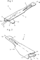
- Weitere Merkmale und Vorteile der Erfindung ergeben sich anhand der zugehörigen Zeichnungen, in denen ein Ausführungsbeispiel eines erfindungsgemäßen medizinischen Schneidinstruments zum Schneiden von Muskeln und Sehnen nur beispielhaft dargestellt ist, ohne die Erfindung auf dieses Ausführungsbeispiel zu beschränken. In den Zeichnungen zeigt:
- Fig. 1
- eine perspektivische Seitenansicht eines erfindungsgemäßen medizinischen Schneidinstruments;
- Fig. 2
- eine um 90° gedrehte perspektivische Ansicht des Schneidinstruments gemäß
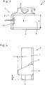
Fig. 1 ; - Fig. 3
- eine Vorderansicht des Schneidinstruments gemäß
Fig. 1 und - Fig. 4
- eine Unteransicht des distalen Endes des Schneidinstruments gemäß
Fig. 1 . - Die Abbildungen
Fig.1 und 2 zeigen perspektivische Ansichten eines medizinischen Schneidinstruments 1 zum Schneiden von Muskeln und Sehnen 2. Dieses, beispielsweise als Sehnenmesser 1 dienende, medizinische Schneidinstrument 1 besteht im Wesentlichen aus einem Instrumentenkörper 3, an dessen proximalem Ende eine Handhabe 4 angeordnet ist und der im Bereich seines distalen Endes mindestens ein mit einer Schneidkante 5 versehenes Schneidmesser 6 aufweist. - Bei der dargestellten Ausführungsform ist der sich distalseitig an die Handhabe 4 anschließende Teil des Instrumentenkörpers 3 als L-förmiges Rechteckprofil 7 ausgebildet.
- Im Bereich des Schneidmessers 5 ist der Instrumentenkörper 3 rinnenförmig so ausgebildet ist, dass der Instrumentenkörper 3 einen sich in Längsrichtung des Instrumentenkörpers 3 erstreckenden Hohlraum 8 zur Aufnahme und Führung des zu schneidenden Muskel-/Sehnengewebes 2 aufweist, wobei der Instrumentenkörper 3 eine sich in Längsrichtung des Instrumentenkörpers 3 erstreckende Öffnung 9 aufweist und das Schneidmesser 6 eine Seite des Instrumentenkörpers 3 bildet.
- Wie weiterhin aus den Abbildungen ersichtlich, ist das Schneidmesser 6 so am Rechteckprofil 7 des Instrumentenkörpers 3 angeordnet, dass die Schneidkante 5 distalseitig quer zur Instrumentenlängsachse 10 des Instrumentenkörpers 3 ausgerichtet ist und der Instrumentenkörper 3 die Schneidkante 5 des Schneidmessers 6 um den Abstand a überragt.
- Die Ausbildung eines Abstandes a zwischen dem distalen Ende des Instrumentenkörpers 3 und der Schneidkante 5 stellt sicher, dass der Muskel-/Sehnenansatz des zu schneidenden Muskel-/Sehnengewebes 2 am Knochen durch das Schneidmesser 5 nicht verletzt wird.
- Alternativ zu der dargestellten Ausführungsform, bei der das Schneidmesser 6 am unteren Rand des Rechteckprofils 7 des Instrumentenkörpers 3 angeordnet ist, ist es auch möglich, das Schneidmesser 6 mit Abstand zum unteren Rand des Rechteckprofils 7 des Instrumentenkörpers 3 anzuordnen. Ebenso ist es möglich, die durch den Abstand zwischen der Schneidkante 5 und der Unterseite der dem Schneidmesser 6 gegenüberliegenden Seite des Rechteckprofils 7 des Instrumentenkörpers 3 gebildete Schnitttiefe s variabel einstellbar auszugestalten.
- Als weitere alternative Ausgestaltungsform ist es möglich, den Instrumentenkörper 3 nicht als Rechteckprofil 7, sondern im Querschnitt gebogen auszubilden.
- Um ein seitliches Einhaken des Sehnenmessers 1 in ein zu schneidendes Sehnenbündel zu erleichtern, überragt das Schneidmesser 6 den Instrumentenkörper 3 in Richtung quer zur Instrumentenlängsachse 10 um einen Überstand ü.
- Weiterhin ist, wie insbesondere aus
Fig. 1 und4 ersichtlich, die der Schneidkante 5 gegenüberliegende proximale Seite 11 des Schneidmessers 6 zur Öffnung 9 des Instrumentenkörpers 3 hin schräg zulaufend ausgebildet ist. - Durch die schräge Ausbildung der Seite 11 des Schneidmessers 6 wird das Bündel des Muskel-/Sehnengewebes 2, in das das Sehnenmesser 1 mit dem Überstand ü des Schneidmessers 6 eingehakt wurde, so nach innen in den dreiseitig umschlossenen Hohlraum 8 geleitet, dass die der Öffnung 9 des Instrumentenkörpers 3 gegenüberliegende Innenseite des Instrumentenkörpers 3 eine Führungsfläche 12 für das zu schneidende Muskel-/Sehnengewebe 2 bildet.
- Die Handhabung eines wie zuvor beschrieben aufgebauten Sehnenmessers 1 geschieht wie folgt:
- Der Operateur ergreift das Sehnenmesser 1 an der proximalseitigen Handhabe 4 und führt das Schneidmesser 6 mit seinem den Instrumentenkörper 3 überragenden Überstand ü in Faserrichtung zwischen oder hinter die Fasern des zu schneidenden Muskel-oder Sehnengewebes 2, bis das Muskel- oder Sehnengewebe 2 an der Führungsfläche 12 im Inneren des Hohlraums 8 des Instrumentenkörpers 3 anliegt, wie dies in
Fig. 3 schematisch dargestellt ist. Das Hinführen des Muskel-oder Sehnengewebes 2 hin an die Führungsfläche 12 wird durch die schräg ausgebildete Schneidmesserseite 11 unterstützt. - Sobald der Operateur das Sehnenmesser 1 aus seiner Ausrichtung in Faserrichtung um 90° in eine Lage quer zur Faserrichtung verkippt, kann er mittels der
- Schneidkante 5 des Schneidmessers 6 das Muskel- oder Sehnengewebe 2 an der gewünschten Stelle durchtrennen. Der Abstand a der Schneidkante 5 vom distalen ende des Instrumentenkörpers 3 verhindert dabei, dass das Muskel- oder Sehnengewebe 2 direkt am Knochenansatz abgetrennt werden kann.
- Ein solchermaßen ausgebildetes medizinisches Schneidinstrument 1 zum Schneiden von Muskeln und Sehnen 2 zeichnet sich dadurch aus, dass es bei einfacher Handhabung und einfachem Aufbau ein sicheres Schneiden des Muskel-/Sehnengewebes 2 gewährleistet.
-
- 1
- medizinisches Schneidinstrument / Sehnenmesser
- 2
- Muskel-/Sehnengewebe
- 3
- Instrumentenkörper
- 4
- Handhabe
- 5
- Schneidkante
- 6
- Schneidmesser
- 7
- Rechteckprofil
- 8
- Hohlraum
- 9
- Öffnung
- 10
- Instrumentenlängsachse
- 11
- schräge Schneidmesserseite
- 12
- Führungsfläche
- a
- Abstand
- s
- Schnitttiefe
- ü
- Überstand
Claims (10)
- Medizinisches Schneidinstrument zum Schneiden von Muskeln und Sehnen, mit einem Instrumentenkörper (3), der an seinem proximalem Ende eine Handhabe (4) und im Bereich seines distalen Endes mindestens ein Schneidmesser (6) aufweist,
dadurch gekennzeichnet,
dass der Instrumentenkörper (3) im Bereich des Schneidmessers (5) rinnenförmig so ausgebildet ist, dass der Instrumentenkörper (3) einen sich in Längsrichtung des Instrumentenkörpers (3) erstreckenden Hohlraum (8) zur Aufnahme und Führung des zu schneidenden Muskel-/Sehnengewebes (2) aufweist, wobei der Instrumentenkörper (3) eine sich in Längsrichtung des Instrumentenkörpers (3) erstreckende Öffnung (9) aufweist und das Schneidmesser (6) eine Seite des Instrumentenkörpers (3) bildet. - Medizinisches Schneidinstrument nach Anspruch 1, dadurch gekennzeichnet, dass das Schneidmesser (6) distalseitig eine quer zur Längsrichtung des Instrumentenkörpers (3) ausgerichtete Schneidkante (5) aufweist.
- Medizinisches Schneidinstrument nach Anspruch 2, dadurch gekennzeichnet, dass die der Schneidkante (5) gegenüberliegende proximale Seite (11) des Schneidmessers (6) zur offenen Seite des Instrumentenkörpers (3) hin schräg zulaufend ausgebildet ist.
- Medizinisches Schneidinstrument nach einem der Ansprüche 1 bis 3, dadurch gekennzeichnet, dass das Schneidmesser (6) den Instrumentenkörper (3) in Richtung quer zur Instrumentenlängsachse überragt.
- Medizinisches Schneidinstrument nach einem der Ansprüche 2 bis 4, dadurch gekennzeichnet, dass der Instrumentenkörper (3) die Schneidkante (5) des Schneidmessers (6) in distaler Längsrichtung des Instrumentenkörpers (3) überragt.
- Medizinisches Schneidinstrument nach einem der Ansprüche 1 bis 5, dadurch gekennzeichnet, dass das Schneidmesser (6) eine an die Öffnung (9) des Instrumentenkörpers (3) angrenzende Seite des Instrumentenkörpers (3) bildet.
- Medizinisches Schneidinstrument Anspruch 6, dadurch gekennzeichnet, dass der Abstand zwischen dem Schneidmesser (6) und der dem Schneidmesser (6) gegenüberliegenden, anderen an die Öffnung (9) des Instrumentenkörpers (3) angrenzend Seite des Instrumentenkörpers (3) einstellbar ist.
- Medizinisches Schneidinstrument nach einem der Ansprüche 1 bis 7, dadurch gekennzeichnet, dass die der Öffnung (9) des Instrumentenkörpers (3) gegenüberliegende Innenseite des Instrumentenkörpers (3) eine Führung für das zu schneidende Muskel-/Sehnengewebe (2) bildet.
- Medizinisches Schneidinstrument nach einem der Ansprüche 1 bis 8, dadurch gekennzeichnet, dass der Instrumentenkörper (3) als Rechteckprofil (7) ausgebildet ist.
- Medizinisches Schneidinstrument nach einem der Ansprüche 1 bis 8, dadurch gekennzeichnet, dass der Instrumentenkörper (3) im Querschnitt gebogen ausgebildet ist.
Applications Claiming Priority (1)
| Application Number | Priority Date | Filing Date | Title |
|---|---|---|---|
| DE102011012014A DE102011012014A1 (de) | 2011-02-22 | 2011-02-22 | Medizinisches Schneidinstrument zum Schneiden von Muskeln und Sehnen |
Publications (2)
| Publication Number | Publication Date |
|---|---|
| EP2491866A1 true EP2491866A1 (de) | 2012-08-29 |
| EP2491866B1 EP2491866B1 (de) | 2014-11-05 |
Family
ID=45655104
Family Applications (1)
| Application Number | Title | Priority Date | Filing Date |
|---|---|---|---|
| EP12001083.0A Active EP2491866B1 (de) | 2011-02-22 | 2012-02-18 | Medizinisches Schneidinstrument zum Schneiden von Muskeln und Sehnen |
Country Status (3)
| Country | Link |
|---|---|
| US (1) | US9017354B2 (de) |
| EP (1) | EP2491866B1 (de) |
| DE (1) | DE102011012014A1 (de) |
Cited By (1)
| Publication number | Priority date | Publication date | Assignee | Title |
|---|---|---|---|---|
| US12551686B2 (en) | 2022-07-15 | 2026-02-17 | Vitalmex Internacional S.A. De C.V. | Ventricular assist devices and methods |
Families Citing this family (13)
| Publication number | Priority date | Publication date | Assignee | Title |
|---|---|---|---|---|
| WO2016033647A1 (en) * | 2014-09-02 | 2016-03-10 | Allegra Orthopaedics Limited | A device and method for tendon surgery |
| EP3193748B1 (de) | 2014-09-18 | 2020-07-01 | Mayo Foundation for Medical Education and Research | Weichgewebeschneidegerät |
| US10864055B2 (en) | 2017-10-13 | 2020-12-15 | Sonex Health, Inc. | Tray for a soft tissue cutting device and methods of use |
| ES2907223T3 (es) * | 2018-09-13 | 2022-04-22 | Medacta Int Sa | Herramienta de corte para la incisión horizontal de un tendón |
| EP3908215B1 (de) | 2019-01-11 | 2023-08-02 | Mayo Foundation for Medical Education and Research | Mikroinvasive chirurgische vorrichtung |
| EP3975889B1 (de) | 2019-05-29 | 2024-10-16 | Mayo Foundation for Medical Education and Research | Mikroinvasive chirurgische vorrichtung und verwendungsverfahren |
| PL3815642T3 (pl) | 2019-10-28 | 2023-09-25 | Erbe Elektromedizin Gmbh | Wkład noża i element uszczelniający |
| CN111437008B (zh) * | 2020-04-07 | 2021-06-15 | 常州市第一人民医院 | 腓骨长肌腱全长取腱器及其加工方法 |
| US12004767B2 (en) | 2021-01-08 | 2024-06-11 | Sonex Health, Inc. | Surgical cutting device for ultrasonic guided soft tissue surgery |
| USD989961S1 (en) | 2021-04-30 | 2023-06-20 | Sonex Health, Inc. | Soft tissue cutting device |
| US12251122B2 (en) | 2021-04-30 | 2025-03-18 | Sonex Health, Inc. | Cutting device for trigger finger and other soft tissues |
| US12605181B2 (en) | 2022-01-31 | 2026-04-21 | Sonex Health, Inc. | Trigger thumb treatment devices and methods |
| WO2024044237A1 (en) | 2022-08-25 | 2024-02-29 | Sonex Health, Inc. | De quervain's treatment device |
Citations (6)
| Publication number | Priority date | Publication date | Assignee | Title |
|---|---|---|---|---|
| US4239045A (en) * | 1979-04-04 | 1980-12-16 | Schlein Allen P | Surgical knife |
| DE8421587U1 (de) | 1984-11-22 | Schöttle, Harald, Dr. med., 2000 Hamburg | Tenotom | |
| WO1996011639A1 (en) * | 1994-10-17 | 1996-04-25 | Raymedica, Inc. | Spinal anulus cutter |
| US5601584A (en) * | 1993-10-22 | 1997-02-11 | Zein E. Obagi | Scalpel with integrated visual control aperture |
| WO1999039632A1 (en) * | 1998-02-06 | 1999-08-12 | Evans David K | Device for visualizing, dissecting and harvesting vessels |
| JP2010284478A (ja) * | 2009-06-12 | 2010-12-24 | Hidetaka Ko | 膝蓋腱を切開するメスセット |
Family Cites Families (15)
| Publication number | Priority date | Publication date | Assignee | Title |
|---|---|---|---|---|
| US697902A (en) * | 1902-01-21 | 1902-04-15 | Freeman Leeman Tripp | Linoleum-cutter. |
| US1830692A (en) * | 1930-10-29 | 1931-11-03 | Becker Fritz Heinrich | Multiple cutting tool |
| US3797505A (en) * | 1971-08-10 | 1974-03-19 | H Gilhaus | Planing instrument for calloused skin |
| US5026385A (en) * | 1990-04-03 | 1991-06-25 | Schutte Michael J | Double-bladed scalpel |
| FR2665628B1 (fr) * | 1990-08-10 | 1993-08-06 | Cendis Medical | Appareil pour le prelevement d'un tendon rotulien. |
| US5423825A (en) * | 1992-06-10 | 1995-06-13 | Levine; Andrew S. | Spinal fusion instruments and methods |
| US5447516A (en) * | 1994-05-23 | 1995-09-05 | Gardner; Terry B. | Double-bladed scalpel |
| FR2767469B1 (fr) * | 1997-08-25 | 2000-06-16 | Raphael Mosseri | Dispositif de protection pour un outil coupant et/ou perforant |
| US5951580A (en) * | 1998-03-23 | 1999-09-14 | Ashraf; Bahman | Scalpel having two blades adjustably separable |
| US6179852B1 (en) * | 1999-02-01 | 2001-01-30 | Biomet, Inc. | Carpal tunnel device and method |
| TWI321589B (en) * | 2002-12-27 | 2010-03-11 | Ind Tech Res Inst | A dissecting device for cell and tissue aggregates |
| US8252011B1 (en) * | 2003-04-21 | 2012-08-28 | Osteomed Llc | Minimally invasive technique for performing plantar fasciotomies and surgical instrument for use in such a technique |
| US6905290B1 (en) * | 2003-09-22 | 2005-06-14 | Andrew Casciato, Jr. | Hand rasp with groove blade and adjustable guide for scoring construction material |
| US7322942B2 (en) * | 2004-05-07 | 2008-01-29 | Roche Diagnostics Operations, Inc. | Integrated disposable for automatic or manual blood dosing |
| US7900362B2 (en) * | 2007-04-04 | 2011-03-08 | Pl Medical Company Llc | Miniature disposable safety scalpel |
-
2011
- 2011-02-22 DE DE102011012014A patent/DE102011012014A1/de not_active Withdrawn
-
2012
- 2012-02-18 EP EP12001083.0A patent/EP2491866B1/de active Active
- 2012-02-22 US US13/402,431 patent/US9017354B2/en active Active
Patent Citations (6)
| Publication number | Priority date | Publication date | Assignee | Title |
|---|---|---|---|---|
| DE8421587U1 (de) | 1984-11-22 | Schöttle, Harald, Dr. med., 2000 Hamburg | Tenotom | |
| US4239045A (en) * | 1979-04-04 | 1980-12-16 | Schlein Allen P | Surgical knife |
| US5601584A (en) * | 1993-10-22 | 1997-02-11 | Zein E. Obagi | Scalpel with integrated visual control aperture |
| WO1996011639A1 (en) * | 1994-10-17 | 1996-04-25 | Raymedica, Inc. | Spinal anulus cutter |
| WO1999039632A1 (en) * | 1998-02-06 | 1999-08-12 | Evans David K | Device for visualizing, dissecting and harvesting vessels |
| JP2010284478A (ja) * | 2009-06-12 | 2010-12-24 | Hidetaka Ko | 膝蓋腱を切開するメスセット |
Cited By (1)
| Publication number | Priority date | Publication date | Assignee | Title |
|---|---|---|---|---|
| US12551686B2 (en) | 2022-07-15 | 2026-02-17 | Vitalmex Internacional S.A. De C.V. | Ventricular assist devices and methods |
Also Published As
| Publication number | Publication date |
|---|---|
| EP2491866B1 (de) | 2014-11-05 |
| US20120215240A1 (en) | 2012-08-23 |
| DE102011012014A1 (de) | 2012-08-23 |
| US9017354B2 (en) | 2015-04-28 |
Similar Documents
| Publication | Publication Date | Title |
|---|---|---|
| EP2491866B1 (de) | Medizinisches Schneidinstrument zum Schneiden von Muskeln und Sehnen | |
| DE3918431C1 (de) | ||
| DE19704580C2 (de) | Chirurgischer Fadenschneider | |
| EP2221006B1 (de) | Medizinisches Instrument zum Ergreifen von chirurgischem Nahtmaterial | |
| DE3212828C2 (de) | Chirurgische Klammer und Vorrichtung zum Entfernen von chirurgischen Klammern | |
| DE102011009482B4 (de) | Sicherheitskanüle | |
| DE3403962C2 (de) | ||
| EP0274705A1 (de) | Sonde zur Einführung in den menschlichen oder tierischen Körper, insbesondere Papillotom | |
| DE102004040959A1 (de) | Chirurgisches Instrument | |
| DE2716403A1 (de) | Vorrichtung zum einrichten von knochenbruechen | |
| EP2452644A2 (de) | Repositionszange mit einer Bohrhilfe | |
| DE2609723A1 (de) | Knochennagel | |
| WO2009152919A1 (de) | Vorrichtung zur entfernung von knochengewebe bei endoskopischen operationen | |
| EP2853212B1 (de) | Chirurgisches Instrument | |
| WO2011151039A1 (de) | Gelenk-biopsienadel zur entnahme von gewebeproben | |
| DE102006024756B4 (de) | Chirurgischer Obturator | |
| DE19710432C2 (de) | Nadelhalter | |
| DE102012202434A1 (de) | Medizinisches Instrument | |
| DE102018112346A1 (de) | Medizinisches Instrument | |
| DE102005023414B3 (de) | Vorrichtung zur Durchführung einer transseptalen Punktion | |
| DE202010012285U1 (de) | Blumenanschneider | |
| DE3306954A1 (de) | Vorrichtung zum durchstossen von abschnitten eines drahtes durch einen festkoerper aus nachgiebigem material | |
| EP2258290B1 (de) | Humerusnagel zur Versorgung von Frakturen des Humerus | |
| EP2769688B1 (de) | Medizinisches Instrument mit einem korkenzieherartigen Verbindungselement | |
| DE4004921A1 (de) | Aerztliches instrument, insbesondere fuer die kosmetische chirurgie |
Legal Events
| Date | Code | Title | Description |
|---|---|---|---|
| PUAI | Public reference made under article 153(3) epc to a published international application that has entered the european phase |
Free format text: ORIGINAL CODE: 0009012 |
|
| AK | Designated contracting states |
Kind code of ref document: A1 Designated state(s): AL AT BE BG CH CY CZ DE DK EE ES FI FR GB GR HR HU IE IS IT LI LT LU LV MC MK MT NL NO PL PT RO RS SE SI SK SM TR |
|
| AX | Request for extension of the european patent |
Extension state: BA ME |
|
| RIN1 | Information on inventor provided before grant (corrected) |
Inventor name: WEINMANN, DANIEL Inventor name: FINK, CHRISTIAN, PROF. DR. Inventor name: BERBERICH, SASCHA |
|
| 17P | Request for examination filed |
Effective date: 20130206 |
|
| 17Q | First examination report despatched |
Effective date: 20130513 |
|
| GRAP | Despatch of communication of intention to grant a patent |
Free format text: ORIGINAL CODE: EPIDOSNIGR1 |
|
| RIC1 | Information provided on ipc code assigned before grant |
Ipc: A61B 17/3211 20060101ALN20140627BHEP Ipc: A61B 17/32 20060101ALI20140627BHEP Ipc: A61B 17/00 20060101AFI20140627BHEP Ipc: A61B 17/3213 20060101ALN20140627BHEP |
|
| INTG | Intention to grant announced |
Effective date: 20140718 |
|
| GRAS | Grant fee paid |
Free format text: ORIGINAL CODE: EPIDOSNIGR3 |
|
| GRAA | (expected) grant |
Free format text: ORIGINAL CODE: 0009210 |
|
| AK | Designated contracting states |
Kind code of ref document: B1 Designated state(s): AL AT BE BG CH CY CZ DE DK EE ES FI FR GB GR HR HU IE IS IT LI LT LU LV MC MK MT NL NO PL PT RO RS SE SI SK SM TR |
|
| REG | Reference to a national code |
Ref country code: GB Ref legal event code: FG4D Free format text: NOT ENGLISH |
|
| REG | Reference to a national code |
Ref country code: CH Ref legal event code: EP |
|
| REG | Reference to a national code |
Ref country code: AT Ref legal event code: REF Ref document number: 694157 Country of ref document: AT Kind code of ref document: T Effective date: 20141115 |
|
| REG | Reference to a national code |
Ref country code: IE Ref legal event code: FG4D Free format text: LANGUAGE OF EP DOCUMENT: GERMAN |
|
| REG | Reference to a national code |
Ref country code: DE Ref legal event code: R096 Ref document number: 502012001513 Country of ref document: DE Effective date: 20141218 |
|
| REG | Reference to a national code |
Ref country code: NL Ref legal event code: VDEP Effective date: 20141105 |
|
| REG | Reference to a national code |
Ref country code: LT Ref legal event code: MG4D |
|
| PG25 | Lapsed in a contracting state [announced via postgrant information from national office to epo] |
Ref country code: IS Free format text: LAPSE BECAUSE OF FAILURE TO SUBMIT A TRANSLATION OF THE DESCRIPTION OR TO PAY THE FEE WITHIN THE PRESCRIBED TIME-LIMIT Effective date: 20150305 Ref country code: FI Free format text: LAPSE BECAUSE OF FAILURE TO SUBMIT A TRANSLATION OF THE DESCRIPTION OR TO PAY THE FEE WITHIN THE PRESCRIBED TIME-LIMIT Effective date: 20141105 Ref country code: NO Free format text: LAPSE BECAUSE OF FAILURE TO SUBMIT A TRANSLATION OF THE DESCRIPTION OR TO PAY THE FEE WITHIN THE PRESCRIBED TIME-LIMIT Effective date: 20150205 Ref country code: PT Free format text: LAPSE BECAUSE OF FAILURE TO SUBMIT A TRANSLATION OF THE DESCRIPTION OR TO PAY THE FEE WITHIN THE PRESCRIBED TIME-LIMIT Effective date: 20150305 Ref country code: LT Free format text: LAPSE BECAUSE OF FAILURE TO SUBMIT A TRANSLATION OF THE DESCRIPTION OR TO PAY THE FEE WITHIN THE PRESCRIBED TIME-LIMIT Effective date: 20141105 Ref country code: NL Free format text: LAPSE BECAUSE OF FAILURE TO SUBMIT A TRANSLATION OF THE DESCRIPTION OR TO PAY THE FEE WITHIN THE PRESCRIBED TIME-LIMIT Effective date: 20141105 Ref country code: ES Free format text: LAPSE BECAUSE OF FAILURE TO SUBMIT A TRANSLATION OF THE DESCRIPTION OR TO PAY THE FEE WITHIN THE PRESCRIBED TIME-LIMIT Effective date: 20141105 |
|
| PG25 | Lapsed in a contracting state [announced via postgrant information from national office to epo] |
Ref country code: GR Free format text: LAPSE BECAUSE OF FAILURE TO SUBMIT A TRANSLATION OF THE DESCRIPTION OR TO PAY THE FEE WITHIN THE PRESCRIBED TIME-LIMIT Effective date: 20150206 Ref country code: LV Free format text: LAPSE BECAUSE OF FAILURE TO SUBMIT A TRANSLATION OF THE DESCRIPTION OR TO PAY THE FEE WITHIN THE PRESCRIBED TIME-LIMIT Effective date: 20141105 Ref country code: SE Free format text: LAPSE BECAUSE OF FAILURE TO SUBMIT A TRANSLATION OF THE DESCRIPTION OR TO PAY THE FEE WITHIN THE PRESCRIBED TIME-LIMIT Effective date: 20141105 Ref country code: HR Free format text: LAPSE BECAUSE OF FAILURE TO SUBMIT A TRANSLATION OF THE DESCRIPTION OR TO PAY THE FEE WITHIN THE PRESCRIBED TIME-LIMIT Effective date: 20141105 Ref country code: RS Free format text: LAPSE BECAUSE OF FAILURE TO SUBMIT A TRANSLATION OF THE DESCRIPTION OR TO PAY THE FEE WITHIN THE PRESCRIBED TIME-LIMIT Effective date: 20141105 Ref country code: CY Free format text: LAPSE BECAUSE OF FAILURE TO SUBMIT A TRANSLATION OF THE DESCRIPTION OR TO PAY THE FEE WITHIN THE PRESCRIBED TIME-LIMIT Effective date: 20141105 Ref country code: PL Free format text: LAPSE BECAUSE OF FAILURE TO SUBMIT A TRANSLATION OF THE DESCRIPTION OR TO PAY THE FEE WITHIN THE PRESCRIBED TIME-LIMIT Effective date: 20141105 |
|
| PG25 | Lapsed in a contracting state [announced via postgrant information from national office to epo] |
Ref country code: EE Free format text: LAPSE BECAUSE OF FAILURE TO SUBMIT A TRANSLATION OF THE DESCRIPTION OR TO PAY THE FEE WITHIN THE PRESCRIBED TIME-LIMIT Effective date: 20141105 Ref country code: SK Free format text: LAPSE BECAUSE OF FAILURE TO SUBMIT A TRANSLATION OF THE DESCRIPTION OR TO PAY THE FEE WITHIN THE PRESCRIBED TIME-LIMIT Effective date: 20141105 Ref country code: DK Free format text: LAPSE BECAUSE OF FAILURE TO SUBMIT A TRANSLATION OF THE DESCRIPTION OR TO PAY THE FEE WITHIN THE PRESCRIBED TIME-LIMIT Effective date: 20141105 Ref country code: CZ Free format text: LAPSE BECAUSE OF FAILURE TO SUBMIT A TRANSLATION OF THE DESCRIPTION OR TO PAY THE FEE WITHIN THE PRESCRIBED TIME-LIMIT Effective date: 20141105 |
|
| REG | Reference to a national code |
Ref country code: DE Ref legal event code: R097 Ref document number: 502012001513 Country of ref document: DE |
|
| PLBE | No opposition filed within time limit |
Free format text: ORIGINAL CODE: 0009261 |
|
| STAA | Information on the status of an ep patent application or granted ep patent |
Free format text: STATUS: NO OPPOSITION FILED WITHIN TIME LIMIT |
|
| PG25 | Lapsed in a contracting state [announced via postgrant information from national office to epo] |
Ref country code: LU Free format text: LAPSE BECAUSE OF FAILURE TO SUBMIT A TRANSLATION OF THE DESCRIPTION OR TO PAY THE FEE WITHIN THE PRESCRIBED TIME-LIMIT Effective date: 20150218 |
|
| REG | Reference to a national code |
Ref country code: CH Ref legal event code: PL |
|
| 26N | No opposition filed |
Effective date: 20150806 |
|
| PG25 | Lapsed in a contracting state [announced via postgrant information from national office to epo] |
Ref country code: LI Free format text: LAPSE BECAUSE OF NON-PAYMENT OF DUE FEES Effective date: 20150228 Ref country code: CH Free format text: LAPSE BECAUSE OF NON-PAYMENT OF DUE FEES Effective date: 20150228 Ref country code: MC Free format text: LAPSE BECAUSE OF FAILURE TO SUBMIT A TRANSLATION OF THE DESCRIPTION OR TO PAY THE FEE WITHIN THE PRESCRIBED TIME-LIMIT Effective date: 20141105 |
|
| REG | Reference to a national code |
Ref country code: IE Ref legal event code: MM4A |
|
| REG | Reference to a national code |
Ref country code: FR Ref legal event code: PLFP Year of fee payment: 5 |
|
| PG25 | Lapsed in a contracting state [announced via postgrant information from national office to epo] |
Ref country code: IE Free format text: LAPSE BECAUSE OF NON-PAYMENT OF DUE FEES Effective date: 20150218 |
|
| PG25 | Lapsed in a contracting state [announced via postgrant information from national office to epo] |
Ref country code: SI Free format text: LAPSE BECAUSE OF FAILURE TO SUBMIT A TRANSLATION OF THE DESCRIPTION OR TO PAY THE FEE WITHIN THE PRESCRIBED TIME-LIMIT Effective date: 20141105 |
|
| PG25 | Lapsed in a contracting state [announced via postgrant information from national office to epo] |
Ref country code: RO Free format text: LAPSE BECAUSE OF FAILURE TO SUBMIT A TRANSLATION OF THE DESCRIPTION OR TO PAY THE FEE WITHIN THE PRESCRIBED TIME-LIMIT Effective date: 20141105 |
|
| PG25 | Lapsed in a contracting state [announced via postgrant information from national office to epo] |
Ref country code: MT Free format text: LAPSE BECAUSE OF FAILURE TO SUBMIT A TRANSLATION OF THE DESCRIPTION OR TO PAY THE FEE WITHIN THE PRESCRIBED TIME-LIMIT Effective date: 20141105 |
|
| REG | Reference to a national code |
Ref country code: FR Ref legal event code: PLFP Year of fee payment: 6 |
|
| PG25 | Lapsed in a contracting state [announced via postgrant information from national office to epo] |
Ref country code: SM Free format text: LAPSE BECAUSE OF FAILURE TO SUBMIT A TRANSLATION OF THE DESCRIPTION OR TO PAY THE FEE WITHIN THE PRESCRIBED TIME-LIMIT Effective date: 20141105 Ref country code: BG Free format text: LAPSE BECAUSE OF FAILURE TO SUBMIT A TRANSLATION OF THE DESCRIPTION OR TO PAY THE FEE WITHIN THE PRESCRIBED TIME-LIMIT Effective date: 20141105 Ref country code: HU Free format text: LAPSE BECAUSE OF FAILURE TO SUBMIT A TRANSLATION OF THE DESCRIPTION OR TO PAY THE FEE WITHIN THE PRESCRIBED TIME-LIMIT; INVALID AB INITIO Effective date: 20120218 |
|
| PG25 | Lapsed in a contracting state [announced via postgrant information from national office to epo] |
Ref country code: BE Free format text: LAPSE BECAUSE OF NON-PAYMENT OF DUE FEES Effective date: 20150228 |
|
| PG25 | Lapsed in a contracting state [announced via postgrant information from national office to epo] |
Ref country code: TR Free format text: LAPSE BECAUSE OF FAILURE TO SUBMIT A TRANSLATION OF THE DESCRIPTION OR TO PAY THE FEE WITHIN THE PRESCRIBED TIME-LIMIT Effective date: 20141105 |
|
| REG | Reference to a national code |
Ref country code: FR Ref legal event code: PLFP Year of fee payment: 7 |
|
| REG | Reference to a national code |
Ref country code: DE Ref legal event code: R081 Ref document number: 502012001513 Country of ref document: DE Owner name: KARL STORZ SE & CO. KG INTELLECTUAL PROPERTY, DE Free format text: FORMER OWNER: KARL STORZ GMBH & CO. KG, 78532 TUTTLINGEN, DE Ref country code: DE Ref legal event code: R082 Ref document number: 502012001513 Country of ref document: DE Representative=s name: HOFMEISTER, FRANK, DIPL.-ING., DE Ref country code: DE Ref legal event code: R081 Ref document number: 502012001513 Country of ref document: DE Owner name: KARL STORZ SE & CO. KG, DE Free format text: FORMER OWNER: KARL STORZ GMBH & CO. KG, 78532 TUTTLINGEN, DE |
|
| REG | Reference to a national code |
Ref country code: AT Ref legal event code: MM01 Ref document number: 694157 Country of ref document: AT Kind code of ref document: T Effective date: 20170218 |
|
| PG25 | Lapsed in a contracting state [announced via postgrant information from national office to epo] |
Ref country code: AT Free format text: LAPSE BECAUSE OF NON-PAYMENT OF DUE FEES Effective date: 20170218 |
|
| PG25 | Lapsed in a contracting state [announced via postgrant information from national office to epo] |
Ref country code: MK Free format text: LAPSE BECAUSE OF FAILURE TO SUBMIT A TRANSLATION OF THE DESCRIPTION OR TO PAY THE FEE WITHIN THE PRESCRIBED TIME-LIMIT Effective date: 20141105 |
|
| PG25 | Lapsed in a contracting state [announced via postgrant information from national office to epo] |
Ref country code: AL Free format text: LAPSE BECAUSE OF FAILURE TO SUBMIT A TRANSLATION OF THE DESCRIPTION OR TO PAY THE FEE WITHIN THE PRESCRIBED TIME-LIMIT Effective date: 20141105 |
|
| P01 | Opt-out of the competence of the unified patent court (upc) registered |
Effective date: 20230527 |
|
| PGFP | Annual fee paid to national office [announced via postgrant information from national office to epo] |
Ref country code: GB Payment date: 20260223 Year of fee payment: 15 |
|
| PGFP | Annual fee paid to national office [announced via postgrant information from national office to epo] |
Ref country code: DE Payment date: 20260220 Year of fee payment: 15 |
|
| PGFP | Annual fee paid to national office [announced via postgrant information from national office to epo] |
Ref country code: IT Payment date: 20260220 Year of fee payment: 15 |
|
| PGFP | Annual fee paid to national office [announced via postgrant information from national office to epo] |
Ref country code: FR Payment date: 20260224 Year of fee payment: 15 |