EP2490867B1 - A robot part and a method for protecting a robot part - Google Patents
A robot part and a method for protecting a robot part Download PDFInfo
- Publication number
- EP2490867B1 EP2490867B1 EP09740131.9A EP09740131A EP2490867B1 EP 2490867 B1 EP2490867 B1 EP 2490867B1 EP 09740131 A EP09740131 A EP 09740131A EP 2490867 B1 EP2490867 B1 EP 2490867B1
- Authority
- EP
- European Patent Office
- Prior art keywords
- robot
- shroud
- impact absorbing
- absorbing structure
- robot part
- Prior art date
- Legal status (The legal status is an assumption and is not a legal conclusion. Google has not performed a legal analysis and makes no representation as to the accuracy of the status listed.)
- Active
Links
Images

Classifications
-
- B—PERFORMING OPERATIONS; TRANSPORTING
- B25—HAND TOOLS; PORTABLE POWER-DRIVEN TOOLS; MANIPULATORS
- B25J—MANIPULATORS; CHAMBERS PROVIDED WITH MANIPULATION DEVICES
- B25J19/00—Accessories fitted to manipulators, e.g. for monitoring, for viewing; Safety devices combined with or specially adapted for use in connection with manipulators
- B25J19/0091—Shock absorbers
-
- Y—GENERAL TAGGING OF NEW TECHNOLOGICAL DEVELOPMENTS; GENERAL TAGGING OF CROSS-SECTIONAL TECHNOLOGIES SPANNING OVER SEVERAL SECTIONS OF THE IPC; TECHNICAL SUBJECTS COVERED BY FORMER USPC CROSS-REFERENCE ART COLLECTIONS [XRACs] AND DIGESTS
- Y10—TECHNICAL SUBJECTS COVERED BY FORMER USPC
- Y10T—TECHNICAL SUBJECTS COVERED BY FORMER US CLASSIFICATION
- Y10T403/00—Joints and connections
- Y10T403/45—Flexibly connected rigid members
- Y10T403/453—Flexible sleeve-type coupling
-
- Y—GENERAL TAGGING OF NEW TECHNOLOGICAL DEVELOPMENTS; GENERAL TAGGING OF CROSS-SECTIONAL TECHNOLOGIES SPANNING OVER SEVERAL SECTIONS OF THE IPC; TECHNICAL SUBJECTS COVERED BY FORMER USPC CROSS-REFERENCE ART COLLECTIONS [XRACs] AND DIGESTS
- Y10—TECHNICAL SUBJECTS COVERED BY FORMER USPC
- Y10T—TECHNICAL SUBJECTS COVERED BY FORMER US CLASSIFICATION
- Y10T74/00—Machine element or mechanism
- Y10T74/20—Control lever and linkage systems
- Y10T74/20207—Multiple controlling elements for single controlled element
- Y10T74/20305—Robotic arm
-
- Y—GENERAL TAGGING OF NEW TECHNOLOGICAL DEVELOPMENTS; GENERAL TAGGING OF CROSS-SECTIONAL TECHNOLOGIES SPANNING OVER SEVERAL SECTIONS OF THE IPC; TECHNICAL SUBJECTS COVERED BY FORMER USPC CROSS-REFERENCE ART COLLECTIONS [XRACs] AND DIGESTS
- Y10—TECHNICAL SUBJECTS COVERED BY FORMER USPC
- Y10T—TECHNICAL SUBJECTS COVERED BY FORMER US CLASSIFICATION
- Y10T74/00—Machine element or mechanism
- Y10T74/20—Control lever and linkage systems
- Y10T74/20207—Multiple controlling elements for single controlled element
- Y10T74/20305—Robotic arm
- Y10T74/20329—Joint between elements
Definitions
- the present invention in a first aspect relates to a robot part, such as a robot arm or a robot joint, including an impact absorbing structure surrounding the robot part.
- the invention in a second aspect relates to a method for protecting a robot part by surrounding the robot part with an impact absorbing structure.
- a further requirement in terms of safety is that cabling in the robot arm has to be concealed in order to prevent accidents by entanglement.
- the pressure of padding on the outside of the robot structure conflicts with free movement of the cables. The conflict may be resolved by introducing a volume of free space in which the cable can move between the rotating joint components and the padding. However, this enlarges the outer dimensions of the arm thereby compromising its working range.
- the object of the present invention is to improve a protective impact absorbing structure of a robot part including such a structure.
- the object is to meet the need for achieving a free space between the robot part and the impact absorbing structure without the drawbacks normally entailing such a construction.
- a robot part of the introductionally specified kind includes the specific features that the impact absorbing structure includes a shroud surrounding the robot part and at least two spacing elements on which the shroud is mounted such that an interspace is formed between the shroud and the robot part and that at least one of the spacing elements mounts the shroud elastically.
- the energy developed from an impact on the shroud is taken up by the spacing element that elastically mounts the shroud.
- the shroud can be provided with a much thinner layer of padding material than without this elastic mounting.
- With a sufficient elasticity of the mounting it is possible to completely leave out any layer of padding material on the shroud.
- the dimension of the impact absorbing structure will be substantially reduced in comparison with a structure without such elastic mounting where the complete impact energy has to be absorbed by a surrounding padding.
- both the spacing elements mount the shroud elastically.
- the advantages mentioned above gained by the invention are more accentuated with this embodiment since the elastic mounting of the shroud is more complete and homogeneous.
- the impact effect therefore will be more independent with respect of the location of the impact on the shroud.
- the shroud is mounted at each of its end with the elastic spacing elements.
- At least one of said spacing elements is at least partly made of padding material.
- At least one of the spacing elements includes a first section connected to the shroud, a second section connected to the robot part and an intermediate section connecting the first and second sections, which intermediate section has a higher flexibility than each of the first and second sections.
- the elasticity of the mounting can be further increased.
- the intermediate section has smaller dimensions in at least one direction than the first and second sections.
- the spacing element has a generally annular shape, defining an axis, whereby the first and second sections are axially separated by the intermediate section and the intermediate section has a smaller radial thickness than the first and second sections.
- the arrangement thereby provides equivalent impact absorption to a full-thickness of padding while preserving a concealed void space for e.g. free movement of cables.
- the robot part includes a joint between a first and a second robot component that are rotatable in relation to each other, and a first of the spacing elements is attached to the first component and a second of the spacing elements is attached to the second component.
- the first spacing element is provided with an outer and inner bearing sleeve, on which outer bearing sleeve the shroud is journalled, and which inner bearing sleeve is journaled on the second component.
- the shroud at least partly is of plastic material.
- the shroud When using plastic material for the shroud it will be possible to find a material that is semi-rigid at a suitable level. Thereby the shroud itself will absorb impact energy to a certain extent by a certain degree of deformation.
- the semi-rigid material is also advantageous for attaining a bodily displacement thereof that is transferred to the spacing elements.
- the shroud is provided with a padding material enclosure attached to the outside of the shroud.
- the impact absorbing structure according to the invention includes the alternative that the shroud has no external padding material, the presence of such an enclosure further increases the advantages of the invention.
- the robot part is provided with two separate impact absorbing mechanisms, a bodily displacement of the plastic shroud to absorb low-frequency energy, and local deformation of the enclosing padding material to absorb highfrequency energy of the initial impact. Deformation of the padding enclosure at the collision site spreads the impact force over a larger area thereby minimizing local contact pressure at the surface.
- the padding enclosure will have a thickness that is many times smaller than a conventional padding enclosure.
- the padding enclosure can have a thickness that is many times larger than the thickness of the shroud.
- Preferably the padding material enclosure has a thickness that is within the range of 1-20 times the thickness of the shroud.
- At least one cable is located within the interspace.
- At least a portion of the interspace has a distance between the robot part and the shroud that is in the range of 1,1 -1,5 times the diameter of the cable.
- the lower limit of the range is normally sufficient to achieve this effect. However a larger clearance results in a greater security in this respect. An unnecessary large clearance should be avoided in order not to reduce the space saving achieved by the invention. Therefore the clearance should be smaller than the upper limit. Although the clearance need not be present along the complete extent of the impact absorbing structure and need not be equal along the complete extension it is preferred that there is a clearance within the specified range along the complete extension.
- a cable has a circular cross section and thus a diameter.
- diameter should be interpreted as the smallest dimension of the cross section of the cable.
- an industrial robot has a part that is surrounded by an impact absorbing structure according to the present invention, in particular to any of the preferred embodiments thereof.
- an impact absorbing structure for a part of an industrial robot includes the features of the impact absorbing structure specified for the robot arm provided with such according to the present invention, in particular to any of the preferred embodiments thereof.
- a method of the initially specified kind includes the specific steps of mounting at least two spacing elements on the robot part, mounting a shroud on the spacing elements such that an interspace is formed between the shroud and the robot part, whereby the shroud is mounted elastically on at least one of the spacing elements.
- the method is carried out in a way such that the impact absorbing structure thereof will have the features specified in the preferred embodiments of the invented robot part.
- the invented industrial robot, the invented impact absorbing structure and the invented method and the preferred embodiments of these have the same advantages as the invented robot part and its preferred embodiments, respectively, which advantages have been described above.
- Fig. 1 is a schematic axial section through a roll-type robot joint, having a first robot component 1 and a second robot component 2, which are rotatable relative to each other.
- the second robot component 2 is journalled in roller bearings 18, 19 on the first robot component 1.
- the joint is covered by an impact absorbing structure.
- the structure has a shroud 3 of semi-rigid plastic material.
- the shroud 3 is enclosed by a padding material enclosure 4.
- the shroud 3 is mounted on the robot part with a first axial flange 5 on a first spacing element 6 fixedly attached to the first robot component 1 and with a second axial flange 7 on a second spacing element 8 fixedly attached to the second robot component 2.
- the spacing elements 6, 8 are made of padding material.
- the padding material can be of any kind commonly used for protecting machine parts such as robot parts. Such materials are well known in the art and need no further description.
- the first spacing element 6 has three sections, a first section 9 on which the first flange 5 of the shroud 3 is mounted, a second section 10 connected to the first robot component 1 and an intermediate section 11 forming a waist between the other two.
- the second spacing element 8 has a first section 12 on which the second flange 7of the shroud 3 is mounted, a second section 13 connected to the second robot component 2 and an intermediate section 14 forming a waist.
- the shroud 3 is non-rotatable in relation to the second robot component 2 and consequently rotatable in relation to the first robot component 1.
- the first spacing element 6 is rotatable in relation to the second robot component 2 as well as in relation to the shroud 3.
- a thin, flexible hardwearing bearing sleeve 15 made from low-friction plastic is provided between the first section 9 of the first spacing element 6 and the shroud 3.
- a similar bearing sleeve 16 is provided between the first section 9 of the first spacing element 6 and the second robot component 2.
- An annular interspace is established between the shroud 3 and the second robot component 2.
- a cable 17 is located in this interspace.
- the interspace provides sufficient space for the cable to move freely therein during rotation of the joint since the thickness of the annular interspace is larger than the diameter of the cable 17.
- the plastic shroud moves bodily as the impact energy is absorbed through viscoelastic deformation of the spacing elements 6, 8 on which it is supported.
- the waist sections 11, 12 of the spacing elements 6, 8 reduce the stiffness of the support and absorb impact energy.
- the padding enclosure 4 on the outside of the shroud contributes to absorb the highfrequency energy of the initial impact.
- the radial deformation of the respective fist section 9, 12 of the spacing elements 6, 8 is relatively small in relation to the total thickness g.
- a 10 mm thick spacing element deforms about 2 mm. This deformation determines the dimensioning of the annular interspace inside the shroud in relation to the diameter of the cable 17, and should thus be at least 2 mm wider than the cable diameter in the example mentioned.
- the padding properties of the arrangement are tuned without affecting the external appearance thereof. Tuning is achieved by adjusting the dimension e, f and g of each spacing element 6, 7 rather than altering the radial thickness of external padding 4.
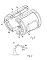
- FIG. 2 illustrates an impact absorbing structure according to another example of the invention.
- the figure shows how the structure can be made by two identical halves which may be screwed together after cabling has been installed on the robot arm.
- Each half consists of an injection-moulded plastic inner chassis 3a, 3b which together form a shroud.
- each chassis 3a, 3b padding material 4a,4b bounded.
- the spacing element is in this example formed by a separate padding insert 8a, 8b on each half and may be bounded into a slot or other locating means in the inside of the chassis 3a, 3b.
- the padding inserts 8a, 8b are arranged to be located in an annular groove running around the outer surface of the robot component (not shown) to which it is to be attached. Slot 20 provides a cable entry.
- Fig. 3 schematically illustrates an industrial robot 101 that is provided with an impact absorbing structure 102 according to the invention, around a rotational joint 103 of the robot.
Landscapes
- Engineering & Computer Science (AREA)
- Robotics (AREA)
- Mechanical Engineering (AREA)
- Manipulator (AREA)
Priority Applications (1)
| Application Number | Priority Date | Filing Date | Title |
|---|---|---|---|
| PL09740131T PL2490867T3 (pl) | 2009-10-22 | 2009-10-22 | Część robota i sposób zabezpieczenia części robota |
Applications Claiming Priority (1)
| Application Number | Priority Date | Filing Date | Title |
|---|---|---|---|
| PCT/EP2009/063922 WO2011047724A1 (en) | 2009-10-22 | 2009-10-22 | A robot part and a method for protecting a robot part |
Publications (2)
| Publication Number | Publication Date |
|---|---|
| EP2490867A1 EP2490867A1 (en) | 2012-08-29 |
| EP2490867B1 true EP2490867B1 (en) | 2014-08-06 |
Family
ID=41463051
Family Applications (1)
| Application Number | Title | Priority Date | Filing Date |
|---|---|---|---|
| EP09740131.9A Active EP2490867B1 (en) | 2009-10-22 | 2009-10-22 | A robot part and a method for protecting a robot part |
Country Status (6)
| Country | Link |
|---|---|
| US (1) | US8584547B2 (pl) |
| EP (1) | EP2490867B1 (pl) |
| CN (1) | CN102112275B (pl) |
| ES (1) | ES2511869T3 (pl) |
| PL (1) | PL2490867T3 (pl) |
| WO (1) | WO2011047724A1 (pl) |
Families Citing this family (16)
| Publication number | Priority date | Publication date | Assignee | Title |
|---|---|---|---|---|
| CN102431042B (zh) * | 2011-09-19 | 2014-06-11 | 浙江中控研究院有限公司 | 一种机器人摔倒保护机构 |
| US9092698B2 (en) | 2012-06-21 | 2015-07-28 | Rethink Robotics, Inc. | Vision-guided robots and methods of training them |
| US9579806B2 (en) | 2012-08-23 | 2017-02-28 | Rethink Robotics, Inc. | Robotic power and signal distribution using laminated cable with separator webs |
| US10179414B2 (en) | 2013-06-18 | 2019-01-15 | Rj Hanlon Company, Inc. | Protective ring for automated equipment axis pivot points |
| US10265867B2 (en) * | 2013-06-20 | 2019-04-23 | Lincoln Global, Inc. | Robotic accessory mounting assembly |
| US20150068350A1 (en) | 2013-09-10 | 2015-03-12 | Seiko Epson Corporation | Robot arm and robot |
| JP6337432B2 (ja) | 2013-09-10 | 2018-06-06 | セイコーエプソン株式会社 | 関節駆動装置及びロボット |
| CN104440941B (zh) * | 2013-09-13 | 2018-02-13 | 精工爱普生株式会社 | 机械手臂以及机器人 |
| JP6677441B2 (ja) * | 2014-10-20 | 2020-04-08 | 株式会社デンソーウェーブ | ロボット、ロボットの形状設計方法 |
| EP3221096B1 (en) * | 2014-11-19 | 2023-06-14 | ABB Schweiz AG | A cable-management system, a rotary joint and a robot |
| US11007636B2 (en) | 2017-03-31 | 2021-05-18 | Kinova Inc. | Articulated mechanism with protective sleeve at joint |
| EP3427904B1 (de) * | 2017-07-13 | 2020-06-10 | Siemens Aktiengesellschaft | Anordnung mit einem manipulator und einer begrenzungseinrichtung zur begrenzung des arbeitsbereichs |
| CN107457802B (zh) * | 2017-09-13 | 2020-10-09 | 北京理工大学 | 一种仿人机器人摔倒保护装置 |
| CN107825465A (zh) * | 2017-11-14 | 2018-03-23 | 徐州欧普莱斯工业机械有限公司 | 一种防护关节损伤的多关节机械臂 |
| FR3075681B1 (fr) * | 2017-12-27 | 2020-08-28 | Softbank Robotics Europe | Securisation d'une articulation d'un robot |
| JP7387257B2 (ja) * | 2018-09-21 | 2023-11-28 | オークマ株式会社 | ロボットユニット |
Family Cites Families (12)
| Publication number | Priority date | Publication date | Assignee | Title |
|---|---|---|---|---|
| JPH02292186A (ja) * | 1989-05-08 | 1990-12-03 | Mitsubishi Heavy Ind Ltd | ロボット |
| JP3081281B2 (ja) | 1991-07-18 | 2000-08-28 | 中部電力株式会社 | 配電線作業用マニピュレータ |
| US5697480A (en) * | 1995-03-22 | 1997-12-16 | Syron Engineering & Manufacturing Corporation | Breakaway mount for robot arm |
| JPH0957680A (ja) * | 1995-08-18 | 1997-03-04 | Tokico Ltd | 工業用ロボット |
| DE29514892U1 (de) * | 1995-09-16 | 1995-11-23 | Fa. Carl Zeiss, 89518 Heidenheim | Kollisionsschutz für den Meßarm eines Koordinatenmeßgerätes |
| EP0988939A1 (en) * | 1998-09-10 | 2000-03-29 | Fanuc Ltd | Industrial robot |
| GB0114406D0 (en) * | 2001-06-13 | 2001-08-08 | Oliver Crispin Consulting Ltd | Improvements in and relating to robotic arms |
| JP2003060004A (ja) * | 2001-08-20 | 2003-02-28 | Yaskawa Electric Corp | ロボットハンド |
| JP3652643B2 (ja) * | 2001-12-25 | 2005-05-25 | 本田技研工業株式会社 | 脚式移動ロボットの着床衝撃緩衝装置 |
| EP1474653B1 (en) * | 2002-02-14 | 2013-01-02 | Faro Technologies Inc. | Portable coordinate measurement machine with integrated line laser scanner |
| KR100567186B1 (ko) * | 2003-10-01 | 2006-04-04 | 한국과학기술원 | 충격흡수구조를 가지는 로봇 팔 |
| US8402860B2 (en) * | 2007-10-10 | 2013-03-26 | Panasonic Corporation | Structure, manipulator and structure control system |
-
2009
- 2009-10-22 PL PL09740131T patent/PL2490867T3/pl unknown
- 2009-10-22 CN CN200980102636.4A patent/CN102112275B/zh active Active
- 2009-10-22 EP EP09740131.9A patent/EP2490867B1/en active Active
- 2009-10-22 ES ES09740131.9T patent/ES2511869T3/es active Active
- 2009-10-22 WO PCT/EP2009/063922 patent/WO2011047724A1/en not_active Ceased
-
2010
- 2010-07-01 US US12/829,049 patent/US8584547B2/en not_active Expired - Fee Related
Also Published As
| Publication number | Publication date |
|---|---|
| US8584547B2 (en) | 2013-11-19 |
| EP2490867A1 (en) | 2012-08-29 |
| CN102112275B (zh) | 2016-03-16 |
| ES2511869T3 (es) | 2014-10-23 |
| CN102112275A (zh) | 2011-06-29 |
| WO2011047724A1 (en) | 2011-04-28 |
| US20110095457A1 (en) | 2011-04-28 |
| PL2490867T3 (pl) | 2015-02-27 |
Similar Documents
| Publication | Publication Date | Title |
|---|---|---|
| EP2490867B1 (en) | A robot part and a method for protecting a robot part | |
| KR101256285B1 (ko) | 토크 센싱 및 감속 기능 구비 캠 기반 통합 안전 관절 유니트 | |
| US9272415B2 (en) | Robot device | |
| US20140137687A1 (en) | Robot | |
| US4254985A (en) | Damping ring for rotating assemblies | |
| US20170341239A1 (en) | Robot including tool having shock-absorbing member | |
| KR101413152B1 (ko) | 마찰감소용 볼을 구비한 구 관절 및 델타로봇 | |
| CN110682326B (zh) | 水平多关节机器人 | |
| CN111843984A (zh) | 水平多关节机器人 | |
| US20140137689A1 (en) | Robot | |
| KR102277847B1 (ko) | 로봇팔용 외피 구조체 | |
| EP3037321B1 (en) | Steering device | |
| CN105522591A (zh) | 机器人及机器人的形状设计方法 | |
| JP2025085365A (ja) | ロボット | |
| KR102717721B1 (ko) | 협동로봇 충돌 안전 시스템 및 이를 이용하는 협동로봇 | |
| KR100567186B1 (ko) | 충격흡수구조를 가지는 로봇 팔 | |
| KR101801899B1 (ko) | 케이블 보호 장치 | |
| US20140137686A1 (en) | Robot | |
| CN109606025B (zh) | 一种机器人底盘 | |
| JP2020011374A (ja) | 水平多関節ロボット | |
| CN110997253A (zh) | 包括能够通过弯曲延展或收回的保护装置的执行器装置 | |
| US20140138176A1 (en) | Vehicle bonnet structure for pedestrian protection | |
| KR102515354B1 (ko) | 직교 로봇 | |
| CN117503354A (zh) | 刀片式无菌化的联轴传动系统 | |
| CN219452830U (zh) | 一种具有降噪功能的减速机机壳 |
Legal Events
| Date | Code | Title | Description |
|---|---|---|---|
| PUAI | Public reference made under article 153(3) epc to a published international application that has entered the european phase |
Free format text: ORIGINAL CODE: 0009012 |
|
| 17P | Request for examination filed |
Effective date: 20120522 |
|
| AK | Designated contracting states |
Kind code of ref document: A1 Designated state(s): AT BE BG CH CY CZ DE DK EE ES FI FR GB GR HR HU IE IS IT LI LT LU LV MC MK MT NL NO PL PT RO SE SI SK SM TR |
|
| DAX | Request for extension of the european patent (deleted) | ||
| GRAP | Despatch of communication of intention to grant a patent |
Free format text: ORIGINAL CODE: EPIDOSNIGR1 |
|
| INTG | Intention to grant announced |
Effective date: 20140505 |
|
| GRAS | Grant fee paid |
Free format text: ORIGINAL CODE: EPIDOSNIGR3 |
|
| GRAA | (expected) grant |
Free format text: ORIGINAL CODE: 0009210 |
|
| AK | Designated contracting states |
Kind code of ref document: B1 Designated state(s): AT BE BG CH CY CZ DE DK EE ES FI FR GB GR HR HU IE IS IT LI LT LU LV MC MK MT NL NO PL PT RO SE SI SK SM TR |
|
| REG | Reference to a national code |
Ref country code: GB Ref legal event code: FG4D |
|
| REG | Reference to a national code |
Ref country code: AT Ref legal event code: REF Ref document number: 680794 Country of ref document: AT Kind code of ref document: T Effective date: 20140815 Ref country code: CH Ref legal event code: EP |
|
| REG | Reference to a national code |
Ref country code: IE Ref legal event code: FG4D |
|
| REG | Reference to a national code |
Ref country code: DE Ref legal event code: R096 Ref document number: 602009025808 Country of ref document: DE Effective date: 20140918 |
|
| REG | Reference to a national code |
Ref country code: ES Ref legal event code: FG2A Ref document number: 2511869 Country of ref document: ES Kind code of ref document: T3 Effective date: 20141023 |
|
| REG | Reference to a national code |
Ref country code: SE Ref legal event code: TRGR |
|
| REG | Reference to a national code |
Ref country code: AT Ref legal event code: MK05 Ref document number: 680794 Country of ref document: AT Kind code of ref document: T Effective date: 20140806 |
|
| REG | Reference to a national code |
Ref country code: NL Ref legal event code: VDEP Effective date: 20140806 |
|
| REG | Reference to a national code |
Ref country code: LT Ref legal event code: MG4D |
|
| PG25 | Lapsed in a contracting state [announced via postgrant information from national office to epo] |
Ref country code: BG Free format text: LAPSE BECAUSE OF FAILURE TO SUBMIT A TRANSLATION OF THE DESCRIPTION OR TO PAY THE FEE WITHIN THE PRESCRIBED TIME-LIMIT Effective date: 20141106 Ref country code: LT Free format text: LAPSE BECAUSE OF FAILURE TO SUBMIT A TRANSLATION OF THE DESCRIPTION OR TO PAY THE FEE WITHIN THE PRESCRIBED TIME-LIMIT Effective date: 20140806 Ref country code: NO Free format text: LAPSE BECAUSE OF FAILURE TO SUBMIT A TRANSLATION OF THE DESCRIPTION OR TO PAY THE FEE WITHIN THE PRESCRIBED TIME-LIMIT Effective date: 20141106 Ref country code: GR Free format text: LAPSE BECAUSE OF FAILURE TO SUBMIT A TRANSLATION OF THE DESCRIPTION OR TO PAY THE FEE WITHIN THE PRESCRIBED TIME-LIMIT Effective date: 20141107 Ref country code: FI Free format text: LAPSE BECAUSE OF FAILURE TO SUBMIT A TRANSLATION OF THE DESCRIPTION OR TO PAY THE FEE WITHIN THE PRESCRIBED TIME-LIMIT Effective date: 20140806 Ref country code: PT Free format text: LAPSE BECAUSE OF FAILURE TO SUBMIT A TRANSLATION OF THE DESCRIPTION OR TO PAY THE FEE WITHIN THE PRESCRIBED TIME-LIMIT Effective date: 20141209 |
|
| PG25 | Lapsed in a contracting state [announced via postgrant information from national office to epo] |
Ref country code: NL Free format text: LAPSE BECAUSE OF FAILURE TO SUBMIT A TRANSLATION OF THE DESCRIPTION OR TO PAY THE FEE WITHIN THE PRESCRIBED TIME-LIMIT Effective date: 20140806 Ref country code: CY Free format text: LAPSE BECAUSE OF FAILURE TO SUBMIT A TRANSLATION OF THE DESCRIPTION OR TO PAY THE FEE WITHIN THE PRESCRIBED TIME-LIMIT Effective date: 20140806 Ref country code: LV Free format text: LAPSE BECAUSE OF FAILURE TO SUBMIT A TRANSLATION OF THE DESCRIPTION OR TO PAY THE FEE WITHIN THE PRESCRIBED TIME-LIMIT Effective date: 20140806 Ref country code: HR Free format text: LAPSE BECAUSE OF FAILURE TO SUBMIT A TRANSLATION OF THE DESCRIPTION OR TO PAY THE FEE WITHIN THE PRESCRIBED TIME-LIMIT Effective date: 20140806 Ref country code: AT Free format text: LAPSE BECAUSE OF FAILURE TO SUBMIT A TRANSLATION OF THE DESCRIPTION OR TO PAY THE FEE WITHIN THE PRESCRIBED TIME-LIMIT Effective date: 20140806 Ref country code: IS Free format text: LAPSE BECAUSE OF FAILURE TO SUBMIT A TRANSLATION OF THE DESCRIPTION OR TO PAY THE FEE WITHIN THE PRESCRIBED TIME-LIMIT Effective date: 20141206 |
|
| REG | Reference to a national code |
Ref country code: PL Ref legal event code: T3 |
|
| PG25 | Lapsed in a contracting state [announced via postgrant information from national office to epo] |
Ref country code: EE Free format text: LAPSE BECAUSE OF FAILURE TO SUBMIT A TRANSLATION OF THE DESCRIPTION OR TO PAY THE FEE WITHIN THE PRESCRIBED TIME-LIMIT Effective date: 20140806 Ref country code: CZ Free format text: LAPSE BECAUSE OF FAILURE TO SUBMIT A TRANSLATION OF THE DESCRIPTION OR TO PAY THE FEE WITHIN THE PRESCRIBED TIME-LIMIT Effective date: 20140806 Ref country code: DK Free format text: LAPSE BECAUSE OF FAILURE TO SUBMIT A TRANSLATION OF THE DESCRIPTION OR TO PAY THE FEE WITHIN THE PRESCRIBED TIME-LIMIT Effective date: 20140806 Ref country code: SK Free format text: LAPSE BECAUSE OF FAILURE TO SUBMIT A TRANSLATION OF THE DESCRIPTION OR TO PAY THE FEE WITHIN THE PRESCRIBED TIME-LIMIT Effective date: 20140806 Ref country code: RO Free format text: LAPSE BECAUSE OF FAILURE TO SUBMIT A TRANSLATION OF THE DESCRIPTION OR TO PAY THE FEE WITHIN THE PRESCRIBED TIME-LIMIT Effective date: 20140806 |
|
| REG | Reference to a national code |
Ref country code: DE Ref legal event code: R097 Ref document number: 602009025808 Country of ref document: DE |
|
| PG25 | Lapsed in a contracting state [announced via postgrant information from national office to epo] |
Ref country code: MC Free format text: LAPSE BECAUSE OF FAILURE TO SUBMIT A TRANSLATION OF THE DESCRIPTION OR TO PAY THE FEE WITHIN THE PRESCRIBED TIME-LIMIT Effective date: 20140806 Ref country code: LU Free format text: LAPSE BECAUSE OF FAILURE TO SUBMIT A TRANSLATION OF THE DESCRIPTION OR TO PAY THE FEE WITHIN THE PRESCRIBED TIME-LIMIT Effective date: 20141022 |
|
| REG | Reference to a national code |
Ref country code: CH Ref legal event code: PL |
|
| PLBE | No opposition filed within time limit |
Free format text: ORIGINAL CODE: 0009261 |
|
| STAA | Information on the status of an ep patent application or granted ep patent |
Free format text: STATUS: NO OPPOSITION FILED WITHIN TIME LIMIT |
|
| PG25 | Lapsed in a contracting state [announced via postgrant information from national office to epo] |
Ref country code: BE Free format text: LAPSE BECAUSE OF NON-PAYMENT OF DUE FEES Effective date: 20141031 |
|
| 26N | No opposition filed |
Effective date: 20150507 |
|
| GBPC | Gb: european patent ceased through non-payment of renewal fee |
Effective date: 20141106 |
|
| REG | Reference to a national code |
Ref country code: IE Ref legal event code: MM4A |
|
| PG25 | Lapsed in a contracting state [announced via postgrant information from national office to epo] |
Ref country code: CH Free format text: LAPSE BECAUSE OF NON-PAYMENT OF DUE FEES Effective date: 20141031 Ref country code: LI Free format text: LAPSE BECAUSE OF NON-PAYMENT OF DUE FEES Effective date: 20141031 |
|
| REG | Reference to a national code |
Ref country code: FR Ref legal event code: PLFP Year of fee payment: 7 |
|
| PG25 | Lapsed in a contracting state [announced via postgrant information from national office to epo] |
Ref country code: GB Free format text: LAPSE BECAUSE OF NON-PAYMENT OF DUE FEES Effective date: 20141106 Ref country code: IE Free format text: LAPSE BECAUSE OF NON-PAYMENT OF DUE FEES Effective date: 20141022 |
|
| PG25 | Lapsed in a contracting state [announced via postgrant information from national office to epo] |
Ref country code: SI Free format text: LAPSE BECAUSE OF FAILURE TO SUBMIT A TRANSLATION OF THE DESCRIPTION OR TO PAY THE FEE WITHIN THE PRESCRIBED TIME-LIMIT Effective date: 20140806 |
|
| PG25 | Lapsed in a contracting state [announced via postgrant information from national office to epo] |
Ref country code: SM Free format text: LAPSE BECAUSE OF FAILURE TO SUBMIT A TRANSLATION OF THE DESCRIPTION OR TO PAY THE FEE WITHIN THE PRESCRIBED TIME-LIMIT Effective date: 20140806 |
|
| PG25 | Lapsed in a contracting state [announced via postgrant information from national office to epo] |
Ref country code: TR Free format text: LAPSE BECAUSE OF FAILURE TO SUBMIT A TRANSLATION OF THE DESCRIPTION OR TO PAY THE FEE WITHIN THE PRESCRIBED TIME-LIMIT Effective date: 20140806 Ref country code: MT Free format text: LAPSE BECAUSE OF FAILURE TO SUBMIT A TRANSLATION OF THE DESCRIPTION OR TO PAY THE FEE WITHIN THE PRESCRIBED TIME-LIMIT Effective date: 20140806 Ref country code: HU Free format text: LAPSE BECAUSE OF FAILURE TO SUBMIT A TRANSLATION OF THE DESCRIPTION OR TO PAY THE FEE WITHIN THE PRESCRIBED TIME-LIMIT; INVALID AB INITIO Effective date: 20091022 Ref country code: BE Free format text: LAPSE BECAUSE OF FAILURE TO SUBMIT A TRANSLATION OF THE DESCRIPTION OR TO PAY THE FEE WITHIN THE PRESCRIBED TIME-LIMIT Effective date: 20140806 |
|
| REG | Reference to a national code |
Ref country code: FR Ref legal event code: PLFP Year of fee payment: 8 |
|
| REG | Reference to a national code |
Ref country code: FR Ref legal event code: PLFP Year of fee payment: 9 |
|
| PG25 | Lapsed in a contracting state [announced via postgrant information from national office to epo] |
Ref country code: MK Free format text: LAPSE BECAUSE OF FAILURE TO SUBMIT A TRANSLATION OF THE DESCRIPTION OR TO PAY THE FEE WITHIN THE PRESCRIBED TIME-LIMIT Effective date: 20140806 |
|
| REG | Reference to a national code |
Ref country code: FR Ref legal event code: PLFP Year of fee payment: 10 |
|
| REG | Reference to a national code |
Ref country code: ES Ref legal event code: PC2A Owner name: ABB SCHWEIZ AG Effective date: 20191030 |
|
| REG | Reference to a national code |
Ref country code: DE Ref legal event code: R081 Ref document number: 602009025808 Country of ref document: DE Owner name: ABB SCHWEIZ AG, CH Free format text: FORMER OWNER: ABB RESEARCH LTD., ZUERICH, CH |
|
| PGFP | Annual fee paid to national office [announced via postgrant information from national office to epo] |
Ref country code: ES Payment date: 20231227 Year of fee payment: 15 |
|
| PGFP | Annual fee paid to national office [announced via postgrant information from national office to epo] |
Ref country code: SE Payment date: 20231019 Year of fee payment: 15 Ref country code: IT Payment date: 20231026 Year of fee payment: 15 Ref country code: FR Payment date: 20231025 Year of fee payment: 15 |
|
| PGFP | Annual fee paid to national office [announced via postgrant information from national office to epo] |
Ref country code: PL Payment date: 20231013 Year of fee payment: 15 |
|
| PGFP | Annual fee paid to national office [announced via postgrant information from national office to epo] |
Ref country code: DE Payment date: 20241021 Year of fee payment: 16 |
|
| REG | Reference to a national code |
Ref country code: SE Ref legal event code: EUG |
|
| PG25 | Lapsed in a contracting state [announced via postgrant information from national office to epo] |
Ref country code: FR Free format text: LAPSE BECAUSE OF NON-PAYMENT OF DUE FEES Effective date: 20241031 |
|
| PG25 | Lapsed in a contracting state [announced via postgrant information from national office to epo] |
Ref country code: SE Free format text: LAPSE BECAUSE OF NON-PAYMENT OF DUE FEES Effective date: 20241023 Ref country code: IT Free format text: LAPSE BECAUSE OF NON-PAYMENT OF DUE FEES Effective date: 20241022 |
|
| REG | Reference to a national code |
Ref country code: ES Ref legal event code: FD2A Effective date: 20251202 |
|
| PG25 | Lapsed in a contracting state [announced via postgrant information from national office to epo] |
Ref country code: ES Free format text: LAPSE BECAUSE OF NON-PAYMENT OF DUE FEES Effective date: 20241023 |