EP2489979A1 - Vorrichtung zur Erkennung und Vermessung von zylindrischen Oberflächen an feuerfesten keramischen Bauteilen in metallurgischen Anwendungen - Google Patents
Vorrichtung zur Erkennung und Vermessung von zylindrischen Oberflächen an feuerfesten keramischen Bauteilen in metallurgischen Anwendungen Download PDFInfo
- Publication number
- EP2489979A1 EP2489979A1 EP11001378A EP11001378A EP2489979A1 EP 2489979 A1 EP2489979 A1 EP 2489979A1 EP 11001378 A EP11001378 A EP 11001378A EP 11001378 A EP11001378 A EP 11001378A EP 2489979 A1 EP2489979 A1 EP 2489979A1
- Authority
- EP
- European Patent Office
- Prior art keywords
- measuring tube
- camera
- mirror
- distance
- measuring
- Prior art date
- Legal status (The legal status is an assumption and is not a legal conclusion. Google has not performed a legal analysis and makes no representation as to the accuracy of the status listed.)
- Granted
Links
Images


Classifications
-
- G—PHYSICS
- G01—MEASURING; TESTING
- G01B—MEASURING LENGTH, THICKNESS OR SIMILAR LINEAR DIMENSIONS; MEASURING ANGLES; MEASURING AREAS; MEASURING IRREGULARITIES OF SURFACES OR CONTOURS
- G01B11/00—Measuring arrangements characterised by the use of optical techniques
- G01B11/08—Measuring arrangements characterised by the use of optical techniques for measuring diameters
- G01B11/12—Measuring arrangements characterised by the use of optical techniques for measuring diameters internal diameters
-
- H—ELECTRICITY
- H04—ELECTRIC COMMUNICATION TECHNIQUE
- H04N—PICTORIAL COMMUNICATION, e.g. TELEVISION
- H04N7/00—Television systems
- H04N7/18—Closed-circuit television [CCTV] systems, i.e. systems in which the video signal is not broadcast
- H04N7/183—Closed-circuit television [CCTV] systems, i.e. systems in which the video signal is not broadcast for receiving images from a single remote source
Definitions
- the invention relates to a device for detecting and measuring cylindrical surfaces of refractory ceramic components in metallurgical applications.
- FIG. 1 shows a typical metallurgical application without limiting it within the scope of the invention.
- a metallurgical vessel 10 with a refractory lined bottom 12, in which a substantially cylindrical refractory ceramic spout 14 is arranged, which has a central flow opening 16 through which a molten metal flows from the metallurgical vessel 10 in downstream units.
- FIG. 1 it follows that the middle slide plate 18m is displaceable to move from a shut-off position (FIG. FIG. 1 ) to be brought into a position in which all flow openings 16 are behind each other and allow the flow of molten metal.
- the abovementioned components (spout 14, slide plates 18 o, 18 m, 18 u, immersion nozzle 20) have cylindrical inner surfaces for limiting the respective flow opening 16.
- the term "cylindrical” is not to be understood in the exact mathematical sense, but from a technical point of view. It is known that the refractory components wear (erode) by the metallurgical attack of the melt or vice versa that formations on the surfaces (so-called clogging).
- the object of the invention is to provide a way to reliably detect and measure cylindrical surfaces of refractory ceramic components in metallurgical applications, so as to have reliable data available to assess whether or what measures may be necessary to the repaired or replaced affected component.
- the invention provides a device which accommodates the basic idea of an endoscope, but innovatively adapts it with regard to the specific application.
- the basic idea of the invention consists first of all in designing the device so that it produces a "cold Part "and a" hot part.
- "The” hot part is intended to be brought into the area of the component to be tested in order to carry out the desired inspection” locally.
- "The” cold part is at a considerable distance placed in an area where temperatures are much lower, such as room temperature.
- the "cold part” sensitive measuring devices such as cameras can be installed, while the “hot part” is preferably only used to guide measuring beams to the surfaces to be tested.
- the device according to the invention is further based on the idea of providing a camera which detects certain parts of the cylindrical surface of the component to be tested and additionally performs a distance measurement, so that a three-dimensional image of the surface to be checked can be jointly determined from the two pieces of information.
- the camera With the camera thus takes place an optical observation of a particular surface, with the device for distance measurement, an assessment of the distance of the corresponding surface portion to a reference point, for example, the central longitudinal axis of the measuring tube.
- the camera is arranged such that the direction of the associated focal length runs coaxially to the central longitudinal axis of the measuring tube.
- the reflection surface serves to optically detect the surface portion of the ceramic component extending radially at a distance from the central longitudinal axis with the camera.
- the reflection surface opposite portion of the measuring tube is translucent, for example, open.
- the reflection surface preferably extends at an angle of approximately 45 ° to the central longitudinal axis of the measuring tube, wherein larger or smaller angles (45 +/- 10 °) are also possible.
- the angles refer to the main direction of the associated light waves.
- the angle data again are not exactly mathematical, but technically to understand. This is especially true if the reflection surface is not flat, but curved, to detect larger or smaller surface portions of the refractory component can.
- the distance measuring device comprises a laser or a diode, which directs an optical beam onto a mirror arranged in the measuring tube, which passes the beam through the transparent peripheral section of the measuring tube onto the part of the cylindrical surface of the ceramic section detected by the camera Component directs.
- the mirror can extend at a distance from the reflection surface.
- an arrangement is provided in which the mirror is arranged in the axial direction of the measuring tube in front of the reflection surface, for example, on the wall side, ie in the region of the inner wall of the measuring tube.
- the laser source can be arranged so that the beam is parallel to the inner wall of the measuring tube, before it hits the mirror.
- the angle of inclination of the mirror will be correspondingly lower than that of the reflection surface, if the reflected light beam is to strike approximately centrally on the surface of the ceramic component detected by the camera, which is advantageous in order to obtain corresponding data.
- the angle of the mirror is for example 10 to 30 ° with respect to the central longitudinal axis of the measuring tube.
- the measuring tube is cylindrical, for example. Other geometries are also possible.
- the reflection surface and / or the mirror can be formed on its optical side with a heat-resistant coating so as not to be damaged by the high temperatures in the region of the measuring point even over longer measuring times.
- a heat-resistant coating is chromium.
- a chrome finish can easily withstand 400 to 500 ° C in the long run.
- the device can detect optically only a part of the cylindrical surface of the component to be tested regularly.
- the measuring tube is designed to be rotatable and / or axially displaceable at least in the region in which the reflection surface and a possible mirror are arranged. This makes it possible to detect (scrape off) any partial surfaces of the cylinder surface of the component, either continuously or sequentially, and to measure them accordingly.
- the rotation of the measuring tube preferably takes place about the central longitudinal axis. Without further ado, the entire measuring tube, including associated devices such as cameras and lasers, can also be rotated.
- the measuring tube is thermally insulated, at least in the region in which the reflecting surface and a possible mirror are arranged, in order to withstand temperatures of, for example, 800 ° C.
- This insulation may be a mineral fiber insulation disposed behind the mirrors / reflecting surfaces, or in other words between the non-optical sides of the reflecting surface / mirror and the inner wall of the measuring tube.
- an embodiment of the invention provides for the device to be formed with a memory unit on which the images and data received by the camera and the device for distance measurement are detected. These can then be evaluated in an evaluation unit.
- the device of the invention fulfills an important safety aspect not only in connection with the use of the slide plate, but also in relation to the entire system, for example, to prevent a melt breakthrough.
- the device can be used mobile. It is also possible to fix them by means of a device to a metallurgical vessel, so that the received images and data are recorded on defined reference variables.
- the figures show a cylindrical measuring tube 30 with a first end 32, the so-called “cold end” and a second end 34, the so-called “hot end”.
- the measuring tube 30 is expanded and takes in this section a camera 38, here a single-lens reflex camera.
- the camera 38 is aligned in the direction of a reflection surface 40, which is located within the second end 34 of the measuring tube 30 and there extends at an angle of 45 ° to the central longitudinal axis A of the measuring tube 30.
- the measuring tube 30 has a corresponding opening 42 in the adjacent wall section, so that a part of a cylindrical surface 18o of a slide plate 18 can be detected by means of the camera 38 via the reflection surface 40.
- FIG. 2 the course of the cylindrical surface of a new slide plate is shown in dashed lines (18z '), while the solid line (18z) indicates an exemplary state of wear, which is to be detected and evaluated by means of the device according to the invention.
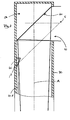
- a laser 44 is arranged in the housing 36, the laser beam 441 parallel and spaced from the inner wall of the measuring tube 30 and thereby encounters a mirror 46, in the direction of the central longitudinal axis A of the measuring tube 30 between the camera 38 and reflection surface 40, the Reflection surface 40 adjacent, is like the Figures 2 . 3 demonstrate.
- FIG. 3 can be further seen that the also flat surface of the mirror 46 extends at an angle ⁇ of about 23 ° with respect to a vertical plane. This value has been selected such that the laser beam reflected at the mirror 46 strikes a central surface portion of the portion of the cylindrical surface 18z of the slider plate 18 detected by the camera 38, which point in FIG FIG. 3 is indicated schematically with S.
- the housing 36 comprises a registration unit (not shown) which stores the images taken by the camera 38 and also the distances of the surface 18z of the slide plate 18 from the central longitudinal axis A of the measuring tube 30 registered by the laser 40.
- the device is designed so that it can also be used on the hot unit. This means that the device after the outflow of the melt from the vessel 10 according to FIG. 1 Preferably, from below into the corresponding through hole 16 of the corresponding component is introduced until the measuring head (section 34 at the "hot end") is in the region of the surface to be tested, as in FIG. 2 shown.
- the entire device can be fixed to the metallurgical vessel, preferably in such a way that the central longitudinal axis A of the measuring tube lies in the axial extension of the ideal center longitudinal axis of the associated flow opening 16.
- the measuring tube 30 is rotated by a certain angle and / or axially displaced by a certain distance to detect an adjacent part of the surface 18z of the slide plate 18. This process can be repeated as often as desired and in any size or small increments, depending on which parts of the slide plate surface to be tested.
- the device is removed again.
- the measuring tube 30 has on the inside a mineral fiber insulation.
- the entire cavity 50 is between reflection surface 40 and inner wall of the measuring tube 30 filled with foam glass.
- the optical surfaces of the reflection surface 40 and the mirror 46 are chromed.
Landscapes
- Physics & Mathematics (AREA)
- General Physics & Mathematics (AREA)
- Engineering & Computer Science (AREA)
- Multimedia (AREA)
- Signal Processing (AREA)
- Length Measuring Devices By Optical Means (AREA)
- Investigating Or Analyzing Materials Using Thermal Means (AREA)
- Measurement Of Optical Distance (AREA)
Abstract
Description
- Die Erfindung betrifft eine Vorrichtung zur Erkennung und Vermessung von zylindrischen Oberflächen an feuerfesten keramischen Bauteilen in metallurgischen Anwendungen.
-
Figur 1 zeigt eine typische metallurgische Anwendung, ohne diese im Rahmen der Erfindung zu beschränken. Zu erkennen ist ein metallurgisches Gefäß 10 mit einem feuerfest ausgekleideten Boden 12, in dem ein im Wesentlichen zylinderförmiger feuerfester keramischer Ausguss 14 angeordnet ist, der eine mittlere Durchflussöffnung 16 aufweist, durch die eine Metallschmelze aus dem metallurgischen Gefäß 10 in nachgeordnete Aggregate fließt. - Dabei folgt dem Ausguss 14, in Strömungsrichtung der Schmelze (Pfeil S) ein Schieberverschluss 18 mit einer oberen Schieberplatte 18o, einer mittleren Schieberplatte 18m und einer unteren Schieberplatte 18u, an die sich ein Tauchausguss 20 anschließt. Alle vorgenannten Bauteile weisen Durchflussöffnungen für die Metallschmelze auf, korrespondierend zum Durchflusskanal 16, weshalb die entsprechenden Abschnitte in
Figur 1 ebenfalls mit 16 gekennzeichnet sind. - Aus
Figur 1 ergibt sich, dass die mittlere Schieberplatte 18m verschiebbar ist, um von einer Absperrposition (Figur 1 ) in eine Position gebracht zu werden, bei der alle Durchflussöffnungen 16 hintereinander liegen und den Durchfluss der Metallschmelze erlauben. - Die vorgenannten Bauteile (Ausguss 14, Schieberplatten 18o, 18m, 18u, Tauchausguss 20) weisen zylindrische innere Oberflächen zur Begrenzung der jeweiligen Durchflussöffnung 16 auf. Der Begriff "zylindrisch" ist dabei nicht im exakten mathematischen Sinne zu verstehen, sondern unter technischen Gesichtspunkten. Es ist bekannt, dass die feuerfesten Bauteile durch den metallurgischen Angriff der Schmelze verschleißen (erodieren) oder umgekehrt, dass sich Aufwachsungen auf den Oberflächen bilden (so genanntes clogging).
- Sowohl Verschleißerscheinungen als auch ein Aufwuchs auf den Oberflächen der Durchgangskanäle 16 stört den Gießvorgang erheblich. Es ist deshalb regelmäßig notwendig, Kenntnisse über die Geometrie der Durchgangskanäle 16 zu haben, um entsprechende Konsequenzen ziehen zu können, beispielsweise den Austausch eines bereits übermäßig verschlissenen Bauteils oder das Ausbrennen/Abschlagen von Aufwachsungen im Durchgangskanal.
- Aufgrund der hohen Temperaturen der entsprechenden Bauteile, die auch nach Abschluss einer Gießsequenz noch lange Zeit mehrere 100 Grad betragen können, ergeben sich Schwierigkeiten bei der Überprüfung der entsprechenden Oberflächen.
- Eine visuelle Beurteilung mit dem Auge ist extrem ungenau und nur auf erhebliche Entfernung möglich. Man hat deshalb versucht, mittels Haken die entsprechenden Oberflächen abzutasten. Auch dabei ergeben sich nur sehr ungenaue Ergebnisse. Häufig wird deshalb auf Erfahrungswerte zurückgegriffen, was in vielen Fällen zu völlig falschen Ergebnissen führt.
- Aufgabe der Erfindung ist es, eine Möglichkeit aufzuzeigen, zylindrische Oberflächen an feuerfesten keramischen Bauteilen in metallurgischen Anwendungen sicher erkennen und vermessen zu können, um so zuverlässige Daten zur Verfügung zu haben, um beurteilen zu können, ob beziehungsweise welche Maßnahmen gegebenenfalls notwendig sind, um das betroffene Bauteil zu reparieren oder auszutauschen.
- Die Erfindung sieht dazu eine Vorrichtung vor, die den Grundgedanken eines Endoskops aufnimmt, diesen aber in Bezug auf die spezifische Anwendung innovativ anpasst. Der Grundgedanke der Erfindung besteht zunächst darin, die Vorrichtung so auszubilden, dass sie einen "kalten Teil" und einen "heißen Teil" aufweist. Der "heiße Teil" ist dazu gedacht, in den Bereich des zu prüfenden Bauteils gebracht zu werden, um entsprechend "vor Ort" die gewünschte Inspektion durchzuführen. Der "kalte Teil" wird in deutlichem Abstand dazu platziert, und zwar in einem Bereich, bei dem deutlich geringere Temperaturen herrschen, beispielsweise Raumtemperatur.
- Entsprechend können in dem "kalten Teil" empfindliche Messvorrichtungen wie Kameras installiert werden, während der "heiße Teil" vorzugsweise nur dazu genutzt wird, Messstrahlen an die zu prüfenden Oberflächen zu führen.
- Vor diesem Hintergrund basiert die erfindungsgemäße Vorrichtung weiters auf der Überlegung, eine Kamera vorzusehen, die bestimmte Teile der zylindrischen Oberfläche des zu prüfenden Bauteils erfasst und zusätzlich eine Abstandsmessung vorzunehmen, so dass sich aus beiden Informationen gemeinsam ein dreidimensionales Bild der zu überprüfenden Oberfläche bestimmen lässt.
- In ihrer allgemeinsten Ausführungsform betrifft die Erfindung eine Vorrichtung zur Erkennung und Vermessung von zylindrischen Oberflächen an feuerfesten keramischen Bauteilen in metallurgischen Anwendungen, mit folgenden Merkmalen:
- einem Messrohr,
- im oder am Messrohr ist eine Kamera angeordnet, deren Objektiv in Richtung auf mindestens eine, im Messrohr angeordnete Reflektionsfläche ausgerichtet ist, wobei
- die Reflektionsfläche im Abstand zum Objektiv und geneigt zur Axialrichtung des Messrohrs verläuft,
- das Messrohr ist in einem der Reflektionsfläche gegenüberliegenden Umfangsabschnitt lichtdurchlässig, so dass die Kamera bei entsprechender Brennweite zwischen Objektiv und Reflektionsfläche einen in radialem Abstand zum Messrohr verlaufenden Teil der zylindrischen Oberfläche des benachbarten feuerfesten keramischen Bauteils erfassen kann,
- im oder am Messrohr ist eine Einrichtung zur Abstandsmessung angeordnet, mit der der Abstand eines Punktes oder eines Flächenabschnitts auf dem von der Kamera erfassten Teil der zylindrischen Oberfläche des feuerfesten keramischen Bauteils zu einem festen Bezugspunkt erfassbar ist.
- Mit der Kamera erfolgt also eine optische Betrachtung einer bestimmten Oberfläche, mit der Einrichtung zur Abstandsmessung eine Beurteilung über den Abstand des entsprechenden Flächenabschnittes zu einem Bezugspunkt, beispielsweise der Mittenlängsachse des Messrohrs.
- Die Kamera ist beispielsweise so angeordnet, dass die Richtung der zugehörigen Brennweite koaxial zur Mittenlängsachse des Messrohres verläuft. Die Reflektionsfläche dient dazu, den radial mit Abstand zur Mittenlängsachse verlaufenden Oberflächenabschnitt des keramischen Bauteils optisch mit der Kamera zu erfassen. Insoweit ist auch der der Reflektionsfläche gegenüberliegende Abschnitt des Messrohres lichtdurchlässig, beispielsweise offen.
- Aus der genannten Anordnung ergibt sich, dass die Reflektionsfläche vorzugsweise unter einem Winkel von etwa 45° zur Mittenlängsachse des Messrohres verläuft, wobei größere oder kleinere Winkel (45 +/- 10°) ebenso möglich sind. Die Winkelangaben beziehen sich auf die Hauptrichtung der zugehörigen Lichtwellen. Insoweit sind die Winkelangaben wiederum nicht exakt mathematisch, sondern technisch zu verstehen. Dies gilt insbesondere dann, wenn die Reflektionsfläche nicht plan ist, sondern gewölbt, um größere oder kleinere Oberflächenabschnitte des feuerfesten Bauteils erfassen zu können.
- Nach einer Ausführungsform umfasst die Einrichtung zur Abstandsmessung einen Laser oder eine Diode, der/die einen optischen Strahl auf einen im Messrohr angeordneten Spiegel richtet, der den Strahl durch den lichtdurchlässigen Umfangsabschnitt des Messrohres hindurch auf den von der Kamera erfassten Teil der zylindrischen Oberfläche des keramischen Bauteils lenkt.
- Für diesen Spiegel gelten die vorstehenden Ausführungen zur Reflektionsfläche analog.
- Dabei ist jedoch zu berücksichtigen, dass der Spiegel beabstandet zur Reflektionsfläche verlaufen kann. Dabei ist insbesondere eine Anordnung vorgesehen, bei der der Spiegel in Axialrichtung des Messrohrs vor der Reflektionsfläche angeordnet ist, und zwar beispielsweise wandseitig, also im Bereich der Innenwand des Messrohres. Die Laserquelle kann dabei so angeordnet sein, dass der Strahl parallel im Abstand zur Innenwand des Messrohrs verläuft, bevor er auf den Spiegel trifft.
- Bei dieser Anordnung wird der Neigungswinkel des Spiegels entsprechend geringer als der der Reflektionsfläche sein, wenn der reflektierte Lichtstrahl etwa mittig auf den von der Kamera erfassten Oberflächenabschnitt des keramischen Bauteils treffen soll, was vorteilhaft ist, um korrespondierende Daten zu erhalten. Insoweit beträgt der Winkel des Spiegels beispielsweise 10 bis 30° in Bezug auf die Mittenlängsachse des Messrohrs.
- Das Messrohr ist beispielsweise zylindrisch. Andere Geometrien sind jedoch ebenfalls möglich.
- Die Reflektionsfläche und/oder der Spiegel können auf ihrer optischen Seite mit einer hitzebeständigen Beschichtung ausgebildet sein, um auch über längere Messzeiten nicht durch die hohen Temperaturen im Bereich der Messstelle beschädigt zu werden. Eine solche mögliche Beschichtung besteht aus Chrom. Eine verchromte Oberfläche kann beispielsweise 400 bis 500° C ohne weiteres langfristig widerstehen.
- Aus der vorstehenden Beschreibung wird deutlich, dass die Vorrichtung regelmäßig nur einen Teil der zylindrischen Oberfläche des zu prüfenden Bauteils optisch erfassen kann. Insoweit sieht eine Ausführungsform vor, dass das Messrohr zumindest in dem Bereich, in dem die Reflektionsfläche und ein etwaiger Spiegel angeordnet sind, drehbar und/oder axial verschiebbar ausgebildet ist. Dies ermöglicht es, entweder kontinuierlich oder sequenzweise beliebige Teilflächen der Zylinderoberfläche des Bauteils zu erfassen (abzurastern) und entsprechend zu vermessen.
- Die Drehung des Messrohres erfolgt vorzugsweise um die Mittenlängsachse. Ohne weiteres kann auch das gesamte Messrohr, einschließlich zugehöriger Einrichtungen wie Kameras und Laser, gedreht werden.
- Es ist gut, wenn das Messrohr zumindest in dem Bereich, in dem die Reflektionsfläche und ein etwaiger Spiegel angeordnet sind, thermisch isoliert wird, um Temperaturen bis beispielsweise 800° C zu widerstehen. Diese Isolierung kann eine Mineralfaserisolierung sein, die hinter den Spiegeln/Reflektionsflächen, oder anders ausgedrückt: zwischen den nicht optischen Seiten der Reflektionsfläche/des Spiegels und der Innenwand des Messrohres angeordnet ist.
- Die Auswertung der von der Kamera aufgenommenen Bilder sowie der Daten der Abstandsmessung kann manuell, vorzugsweise aber elektronisch erfolgen. Dazu sieht eine Ausbildung der Erfindung vor, die Vorrichtung mit einer Speichereinheit auszubilden, auf der die von der Kamera und der Einrichtung zur Abstandsmessung empfangenen Bilder und Daten erfasst werden. Diese können dann in einer Auswerteeinheit ausgewertet werden.
- Ergibt sich dabei beispielsweise, dass der Verschleiß im Bereich einer Durchflussöffnung einer Schieberplatte ein gewisses Maß überschritten hat, ergibt sich daraus unmittelbar die Notwendigkeit, die betroffene Schieberplatte auszutauschen. Damit erfüllt die erfindungsgemäße Vorrichtung einen wichtigen Sicherheitsaspekt nicht nur im Zusammenhang mit der Nutzung der Schieberplatte, sondern auch in Bezug auf die gesamte Anlage, um beispielsweise einen Schmelzendurchbruch zu verhindern.
- Die Vorrichtung kann mobil eingesetzt werden. Ebenso ist es möglich, sie mittels einer Einrichtung an einem metallurgischen Gefäß zu fixieren, so dass die empfangenen Bilder und Daten auf definierte Bezugsgrößen erfasst werden.
- Weitere Merkmale der Erfindung ergeben sich aus den Merkmalen der Unteransprüche sowie den sonstigen Anmeldungsunterlagen.
- Die Erfindung wird nachstehend anhand eines Ausführungsbeispieles näher erläutert.
- Dabei zeigen:
- Figur 2:
- Eine Seitenansicht einer erfindungsgemäßen Vorrichtung zur Erfassung und Messung einer Durchflussöffnung einer Schieber-platte.
- Figur 3:
- Eine vergrößerte Darstellung des Abschnittes der Vorrichtung gemäß
Figur 1 im Bereich der Schieberplatte. - Die Figuren zeigen ein zylindrisches Messrohr 30 mit einem ersten Ende 32, dem so genannten "kalten Ende" und einem zweiten Ende 34, dem so genannten "heißen Ende".
- Am ersten Ende 32 ist das Messrohr 30 erweitert und nimmt in diesem Abschnitt eine Kamera 38 auf, hier eine Spiegelreflexkamera.
- Die Kamera 38 ist in Richtung auf eine Reflektionsfläche 40 ausgerichtet, die sich innerhalb des zweiten Endes 34 des Messrohres 30 befindet und dort in einem Winkel von 45° zur Mittenlängsachse A des Messrohres 30 verläuft.
- Das Messrohr 30 weist im benachbarten Wandabschnitt eine korrespondierende Öffnung 42 auf, so dass mittels der Kamera 38 über die Reflektionsfläche 40 ein Teil einer zylindrischen Oberfläche 18o einer Schieberplatte 18 erfassbar ist.
- In
Figur 2 ist der Verlauf der zylindrischen Oberfläche einer neuen Schieberplatte gestrichelt dargestellt (18z'), während die durchgezogene Linie (18z) einen beispielhaften Verschleißzustand anzeigt, der mittels der erfindungsgemäßen Vorrichtung erfasst und bewertet werden soll. - Durch Einstellung der Brennweite der Kamera 38 auf die Reflektionsfläche 40 lässt sich also ein in radialem Abstand zum Messrohr 30 verlaufender Teil der Oberfläche 18z der Schieberplatte 18 optisch erfassen und betrachten. Diese Aussage allein ist aber nicht ausreichend, den Verschleißgrad der Schieberplatte 18 zu bestimmen, da der Abstand der ursprünglichen Oberfläche zur verschlissenen Oberfläche mittels der Kamera 38 nicht bestimmt werden kann.
- Zu diesem Zweck ist im Gehäuse 36 ein Laser 44 angeordnet, dessen Laserstrahl 441 parallel und mit Abstand zur Innenwand des Messrohrs 30 verläuft und dabei auf einen Spiegel 46 trifft, der in Richtung der Mittenlängsachse A des Messrohrs 30 zwischen Kamera 38 und Reflektionsfläche 40, der Reflektionsfläche 40 benachbart, liegt, wie die
Figuren 2 ,3 zeigen. - Insbesondere
Figur 3 lässt sich weiters entnehmen, dass die ebenfalls plane Oberfläche des Spiegels 46 in einem Winkel β von etwa 23° mit Bezug auf eine Vertikalebene verläuft. Dieser Wert wurde so ausgewählt, dass der am Spiegel 46 reflektierte Laserstrahl auf einen zentralen Flächenabschnitt des von der Kamera 38 erfassten Teils der zylindrischen Oberfläche 18z der Schieberplatte 18 trifft, wobei dieser Punkt inFigur 3 schematisch mit S angegeben ist. - Das Gehäuse 36 umfasst eine (nicht dargestellte) Registriereinheit, die die von der Kamera 38 aufgenommenen Bilder speichert und ebenso die mittels des Lasers 40 registrierten Abstände der Oberfläche 18z der Schieberplatte 18 von der Mittenlängsachse A des Messrohrs 30.
- Mittels entsprechender Kalibrierung lässt sich aus den jeweils bestimmten Abstandswerten millimetergenau feststellen, wie groß der Verschleißgrad im Bereich der Oberfläche 18z der Schieberplatte 18 ist, oder anders ausgedrückt: wie groß der Abstand zwischen der ursprünglichen zylindrischen Oberfläche der neuen Schieberplatte und dem jeweiligen Istzustand ausfällt, wobei über Referenzdaten danach vom Rechner und/oder von einer Bedienungsperson entschieden wird, wie viele Chargen die entsprechende Schieberplatte weiter benutzt werden kann beziehungsweise ob/welche Reparaturen oder ein Austausch notwendig sind.
- Die Vorrichtung ist so ausgeführt, dass sie auch am heißen Aggregat eingesetzt werden kann. Das heißt, dass die Vorrichtung nach dem Ausfließen der Schmelze aus dem Gefäß 10 gemäß
Figur 1 vorzugsweise von unten in die entsprechende Durchgangsbohrung 16 des entsprechenden Bauteils eingeführt wird, bis der Messkopf (Abschnitt 34 am "heißen Ende") im Bereich der zu prüfenden Oberfläche liegt, wie inFigur 2 dargestellt. - Dazu kann die gesamte Vorrichtung am metallurgischen Gefäß fixiert werden, und zwar vorzugsweise so, dass die Mittenlängsachse A des Messrohrs in axialer Verlängerung der idealen Mittenlängsachse der zugehörigen Durchflussöffnung 16 liegt.
- Es erfolgt dann eine erste Aufnahme mittels der Kamera 38 und eine erste Lasertriangulation zur Abstandsmessung. Anschließend wird das Messrohr 30 um einen bestimmten Winkel gedreht und/oder um eine bestimmte Strecke axial verschoben, um einen benachbarten Teil der Oberfläche 18z der Schieberplatte 18 zu erfassen. Dieser Vorgang kann beliebig oft und in beliebig großen oder kleinen Teilschritten wiederholt werden, je nachdem, welche Teile der Schieberplattenoberfläche geprüft werden sollen.
- Anschließend wird die Vorrichtung wieder abgenommen. Um die Standzeit der Vorrichtung zu erhöhen ist im zweiten Abschnitt 34 vorgesehen, dass das Messrohr 30 innenseitig eine Mineralfaserisolierung aufweist. Darüber hinaus ist der gesamte Hohlraum 50 zwischen Reflektionsfläche 40 und Innenwand des Messrohrs 30 mit Schaumglas ausgefüllt. Die optischen Oberflächen der Reflektionsfläche 40 beziehungsweise des Spiegels 46 sind verchromt.
Claims (15)
- Vorrichtung zur Erkennung und Vermessung von zylindrischen Oberflächen an feuerfesten keramischen Bauteilen in metallurgischen Anwendungen, mit folgenden Merkmalen:1.1 einem Messrohr (30)1.2 im oder am Messrohr (30) ist eine Kamera (38) angeordnet, deren Objektiv in Richtung auf mindestens eine, im Messrohr (30) angeordnete Reflektionsfläche (40) ausgerichtet ist, wobei1.3 die Reflektionsfläche (40) im Abstand zum Objektiv und geneigt zur Axialrichtung (A) des Messrohrs (30) verläuft,1.4 das Messrohr (30) ist in einem der Reflektionsfläche (40) gegenüberliegenden Umfangsabschnitt lichtdurchlässig, so dass die Kamera (38) bei entsprechender Brennweite zwischen Objektiv und Reflektionsfläche (40) einen in radialem Abstand zum Messrohr (30) verlaufenden Teil der zylindrischen Oberfläche (18z) des benachbarten feuerfesten keramischen Bauteils (18) erfassen kann,1.5 im oder am Messrohr (30) ist eine Einrichtung (44) zur Abstandsmessung angeordnet, mit der der Abstand eines Punktes oder eines Flächenabschnitts auf dem von der Kamera (38) erfassten Teil der zylindrischen Oberfläche (18z) des feuerfesten keramischen Bauteils (18) zu einem festen Bezugspunkt erfassbar ist.
- Vorrichtung nach Anspruch 1, bei der die Einrichtung (44) zur Abstandsmessung einen Laser oder eine Diode umfasst, der/die einen optischen Strahl (441) auf einen im Messrohr (30) angeordneten Spiegel (46) richtet, der den Strahl (441) durch den lichtdurchlässigen Umfangsabschnitt (42) des Messrohrs (30) hindurch auf den von der Kamera (38) erfassten Teil der zylindrischen Oberfläche (18z) des keramischen Bauteils (18) lenkt.
- Vorrichtung nach Anspruch 1, bei der der lichtdurchlässige Umfangsabschnitt (42) des Messrohrs (30) von einem Wandausschnitt des Messrohrs (30) gebildet wird.
- Vorrichtung nach Anspruch 1, bei der die Reflektionsfläche (40) so angeordnet ist, dass Lichtwellen in einem Winkel von 10-80° umgelenkt werden.
- Vorrichtung nach Anspruch 1, bei der die Reflektionsfläche (40) so angeordnet ist, dass Lichtwellen in einem Winkel von 45 +/- 10° umgelenkt werden.
- Vorrichtung nach Anspruch 2, bei der der Spiegel (46) in Axialrichtung (A) des Messrohrs (30) vor der Reflektionsfläche (40)angeordnet ist.
- Vorrichtung nach Anspruch 2, bei der der Spiegel (46) in einem solchen Winkel geneigt zur Axialrichtung (A) des Messrohrs (30) angeordnet ist, dass der reflektierte Lichtstrahl auf einen zentralen Flächenabschnitt des von der Kamera (38) erfassten Teils der zylindrischen Oberfläche (18z) des keramischen Bauteils (18) gelenkt wird.
- Vorrichtung nach Anspruch 1 mit einem zylindrischen Messrohr (30).
- Vorrichtung nach Anspruch 1, bei der die Reflektionsfläche (40) und/oder der Spiegel (46) auf ihrer optischen Seite eine hitzebeständige Beschichtung aufweisen.
- Vorrichtung nach Anspruch 1, bei der die Reflektionsfläche (40) und/oder der Spiegel (46) auf ihrer optischen Seite verchromt sind.
- Vorrichtung nach Anspruch 1, deren Messrohr (30) um seine Mittenlängsachse (A) drehbar und/oder axial verschiebbar ist.
- Vorrichtung nach Anspruch 1, bei der das Messrohr (30) zumindest in dem Bereich, in dem die Reflektionsfläche (40) und ein etwaiger Spiegel (46) angeordnet sind, thermisch isoliert ausgebildet ist, um Temperaturen bis 800°C zu widerstehen.
- Vorrichtung nach Anspruch 1 mit einer Speichereinheit, auf der die von der Kamera (38) und der Einrichtung (44) zur Abstandsmessung empfangenen Bilder und Daten erfasst werden.
- Vorrichtung nach Anspruch 1, mit einer Auswerteeinheit, mit der die von der Kamera (38) und der Einrichtung (44) zur Abstandsmessung empfangenen Bilder und Daten, gegebenenfalls nach vorheriger Speicherung, ausgewertet werden.
- Vorrichtung nach Anspruch 1 mit einer Einrichtung zur Fixierung der Vorrichtung an einem metallurgischen Gefäß an dem das feuerfeste keramische Bauteil (18) angeordnet ist.
Priority Applications (10)
| Application Number | Priority Date | Filing Date | Title |
|---|---|---|---|
| PL11001378T PL2489979T3 (pl) | 2011-02-19 | 2011-02-19 | Sposób rozpoznawania i pomiaru cylindrycznych powierzchni na ogniotrwałych ceramicznych częściach konstrukcyjnych w zastosowaniach metalurgicznych |
| ES11001378T ES2423061T3 (es) | 2011-02-19 | 2011-02-19 | Procedimiento para el reconocimiento y la medición de superficies cilíndricas en componentes cerámicos resistentes al fuego en aplicaciones metalúrgicas |
| EP11001378.6A EP2489979B1 (de) | 2011-02-19 | 2011-02-19 | Verfahren zur Erkennung und Vermessung von zylindrischen Oberflächen an feuerfesten keramischen Bauteilen in metallurgischen Anwendungen |
| US13/979,059 US20130286184A1 (en) | 2011-02-19 | 2011-12-29 | Apparatus for detecting and measuring cylindrical surfaces on fireproof ceramic components in metallurigal applications |
| RU2013136134/28A RU2563308C2 (ru) | 2011-02-19 | 2011-12-29 | Устройство для обнаружения и измерения цилиндрических поверхностей на огнеупорных керамических деталях при использовании в металлургии |
| KR20137020614A KR101487121B1 (ko) | 2011-02-19 | 2011-12-29 | 야금 분야에서 내화성 세라믹 구성요소의 원통형 표면들을 측정하고 탐지하기 위한 장치 |
| JP2013553819A JP2014509392A (ja) | 2011-02-19 | 2011-12-29 | 冶金応用における耐火性セラミック部品のシリンダー状表面を検出及び測定するための装置 |
| CN2011800669180A CN103348216A (zh) | 2011-02-19 | 2011-12-29 | 用于在冶金应用中识别和测量在耐火的陶瓷构件处的柱状表面的装置 |
| PCT/EP2011/074260 WO2012110167A1 (de) | 2011-02-19 | 2011-12-29 | Vorrichtung zur erkennung und vermessung von zylindrischen oberflächen an feuerfesten keramischen bauteilen in metallurgischen anwendungen |
| BR112013019939-3A BR112013019939B1 (pt) | 2011-02-19 | 2011-12-29 | método para a detecção e medição de superfícies cilíndricas de componentes de cerâmica à prova de fogo em aplicações metalúrgicas |
Applications Claiming Priority (1)
| Application Number | Priority Date | Filing Date | Title |
|---|---|---|---|
| EP11001378.6A EP2489979B1 (de) | 2011-02-19 | 2011-02-19 | Verfahren zur Erkennung und Vermessung von zylindrischen Oberflächen an feuerfesten keramischen Bauteilen in metallurgischen Anwendungen |
Publications (2)
| Publication Number | Publication Date |
|---|---|
| EP2489979A1 true EP2489979A1 (de) | 2012-08-22 |
| EP2489979B1 EP2489979B1 (de) | 2013-06-05 |
Family
ID=44201985
Family Applications (1)
| Application Number | Title | Priority Date | Filing Date |
|---|---|---|---|
| EP11001378.6A Active EP2489979B1 (de) | 2011-02-19 | 2011-02-19 | Verfahren zur Erkennung und Vermessung von zylindrischen Oberflächen an feuerfesten keramischen Bauteilen in metallurgischen Anwendungen |
Country Status (10)
| Country | Link |
|---|---|
| US (1) | US20130286184A1 (de) |
| EP (1) | EP2489979B1 (de) |
| JP (1) | JP2014509392A (de) |
| KR (1) | KR101487121B1 (de) |
| CN (1) | CN103348216A (de) |
| BR (1) | BR112013019939B1 (de) |
| ES (1) | ES2423061T3 (de) |
| PL (1) | PL2489979T3 (de) |
| RU (1) | RU2563308C2 (de) |
| WO (1) | WO2012110167A1 (de) |
Families Citing this family (3)
| Publication number | Priority date | Publication date | Assignee | Title |
|---|---|---|---|---|
| JP6361301B2 (ja) * | 2014-06-12 | 2018-07-25 | 新日鐵住金株式会社 | 溶融金属の流量制御用プレート耐火物の損傷測定装置及び測定方法、並びに流量制御用プレート耐火物の交換判定方法 |
| CH710773B1 (de) | 2015-02-20 | 2019-04-30 | Refractory Intellectual Property Gmbh & Co Kg | Verfahren und Vorrichtung zur Reparatur einer feuerfesten Hülse eines metallurgischen Gefässes. |
| CN107796321B (zh) * | 2017-12-04 | 2024-04-19 | 岭南师范学院 | 一种气缸内径检测设备 |
Citations (2)
| Publication number | Priority date | Publication date | Assignee | Title |
|---|---|---|---|---|
| US6697164B1 (en) * | 1998-08-05 | 2004-02-24 | Cadent Ltd. | Imaging a three-dimensional structure by confocal focussing an array of light beams |
| US6885464B1 (en) * | 1998-06-30 | 2005-04-26 | Sirona Dental Systems Gmbh | 3-D camera for recording surface structures, in particular for dental purposes |
Family Cites Families (24)
| Publication number | Priority date | Publication date | Assignee | Title |
|---|---|---|---|---|
| US4794452A (en) * | 1986-07-31 | 1988-12-27 | Westinghouse Electric Corp. | Through flame optical viewing |
| JPH01145514A (ja) * | 1987-12-02 | 1989-06-07 | Kobe Steel Ltd | 炉内観察測距装置 |
| US4997612A (en) * | 1989-05-03 | 1991-03-05 | Ge Plastics | Polyphenylene ether-polyamide composition |
| JPH0410622A (ja) * | 1990-04-27 | 1992-01-14 | Tokyo Electron Ltd | ドライ洗浄装置 |
| US5212738A (en) * | 1991-04-12 | 1993-05-18 | Martin Marietta Magnesia Specialties Inc. | Scanning laser measurement system |
| JP2799291B2 (ja) * | 1994-06-07 | 1998-09-17 | 動力炉・核燃料開発事業団 | 炉内検査装置 |
| JPH09210622A (ja) * | 1996-02-07 | 1997-08-12 | Kobe Steel Ltd | 高温物体の距離測定方法及び装置 |
| BR9706574A (pt) * | 1996-04-04 | 1999-07-20 | Nippon Steel Corp | Aparelho para a monitoração de superfície de parede |
| GB9713680D0 (en) * | 1997-06-27 | 1997-09-03 | Keymed Medicals & Ind Equip | Improvements in or relating to optical scopes with measuring systems |
| JPH11281331A (ja) * | 1998-03-26 | 1999-10-15 | Toyota Central Res & Dev Lab Inc | 内壁測定装置 |
| CN1166916C (zh) * | 1999-03-16 | 2004-09-15 | 新日本制铁株式会社 | 壁面观察装置 |
| NO312567B2 (no) * | 1999-05-27 | 2002-05-27 | Halfwave As | Fremgangsmate ved maling av materialtykkelsesfordeling |
| DE19957375A1 (de) * | 1999-11-29 | 2001-06-07 | Specialty Minerals Michigan | Verfahren zur Identifikation und Bestimmung der Position insbesondere eines metallurgischen Gefäßes |
| AT409553B (de) * | 2000-09-28 | 2002-09-25 | Voest Alpine Ind Anlagen | Vorrichtung zur chemischen analyse von materialproben sowie metallurgisches gefäss hierfür |
| US7105795B2 (en) * | 2001-07-06 | 2006-09-12 | Palantyr Research, Llc | Imaging system, methodology, and applications employing reciprocal space optical design |
| US6909505B2 (en) * | 2002-06-24 | 2005-06-21 | National Research Council Of Canada | Method and apparatus for molten material analysis by laser induced breakdown spectroscopy |
| JP3917930B2 (ja) * | 2002-11-22 | 2007-05-23 | 新日本製鐵株式会社 | コークス炉の破孔検出装置及び押し出し機 |
| US7027150B1 (en) * | 2004-06-24 | 2006-04-11 | Sandia National Laboratories | Apparatus for measuring the concentration of a species at a distance |
| EP2113552B1 (de) * | 2007-02-22 | 2017-05-24 | Nippon Steel & Sumitomo Metal Corporation | Vorrichtung zur beurteilung von koksofenwandoberflächen, hilfsvorrichtung zur reparatur von koksofenwandoberflächen, verfahren zur beurteilung von koksofenwandoberflächen, hilfsverfahren zur reparatur von koksofenwandoberflächen und computerprogramm |
| DE102008024731B4 (de) * | 2008-05-19 | 2020-08-20 | BAM Bundesanstalt für Materialforschung und -prüfung | Verfahren und Vorrichtung zur Sinterung eines Objektes unter Bestimmung des geometrischen Oberflächenprofils des Objekts |
| BRPI1000301B1 (pt) * | 2010-01-27 | 2017-04-11 | Photonita Ltda | dispositivo óptico para medição e identificação de superfícies cilíndricas por deflectometria aplicado para identificação balística |
| DE102010011217A1 (de) * | 2010-03-11 | 2011-09-15 | Salzgitter Mannesmann Line Pipe Gmbh | Verfahren und Vorrichtung zur Messung der Profilgeometrie von sphärisch gekrümmten, insbesondere zylindrischen Körpern |
| CN101788272A (zh) * | 2010-04-06 | 2010-07-28 | 天津大学 | 基于激光三角法的多方向轴孔内径精密测量方法 |
| US9414024B2 (en) * | 2010-10-12 | 2016-08-09 | Enertechnix, Inc. | Terahertz imaging |
-
2011
- 2011-02-19 EP EP11001378.6A patent/EP2489979B1/de active Active
- 2011-02-19 ES ES11001378T patent/ES2423061T3/es active Active
- 2011-02-19 PL PL11001378T patent/PL2489979T3/pl unknown
- 2011-12-29 KR KR20137020614A patent/KR101487121B1/ko not_active Expired - Fee Related
- 2011-12-29 RU RU2013136134/28A patent/RU2563308C2/ru active
- 2011-12-29 CN CN2011800669180A patent/CN103348216A/zh active Pending
- 2011-12-29 WO PCT/EP2011/074260 patent/WO2012110167A1/de not_active Ceased
- 2011-12-29 US US13/979,059 patent/US20130286184A1/en not_active Abandoned
- 2011-12-29 BR BR112013019939-3A patent/BR112013019939B1/pt not_active IP Right Cessation
- 2011-12-29 JP JP2013553819A patent/JP2014509392A/ja active Pending
Patent Citations (2)
| Publication number | Priority date | Publication date | Assignee | Title |
|---|---|---|---|---|
| US6885464B1 (en) * | 1998-06-30 | 2005-04-26 | Sirona Dental Systems Gmbh | 3-D camera for recording surface structures, in particular for dental purposes |
| US6697164B1 (en) * | 1998-08-05 | 2004-02-24 | Cadent Ltd. | Imaging a three-dimensional structure by confocal focussing an array of light beams |
Also Published As
| Publication number | Publication date |
|---|---|
| PL2489979T3 (pl) | 2013-09-30 |
| CN103348216A (zh) | 2013-10-09 |
| KR101487121B1 (ko) | 2015-01-28 |
| RU2563308C2 (ru) | 2015-09-20 |
| EP2489979B1 (de) | 2013-06-05 |
| WO2012110167A1 (de) | 2012-08-23 |
| ES2423061T3 (es) | 2013-09-17 |
| BR112013019939B1 (pt) | 2021-01-12 |
| RU2013136134A (ru) | 2015-03-27 |
| US20130286184A1 (en) | 2013-10-31 |
| JP2014509392A (ja) | 2014-04-17 |
| KR20130121148A (ko) | 2013-11-05 |
| BR112013019939A2 (pt) | 2016-12-13 |
Similar Documents
| Publication | Publication Date | Title |
|---|---|---|
| EP2205933B1 (de) | Vorrichtung zum optischen vermessen und/oder prüfen von länglichen produkten | |
| DE102016224761A1 (de) | Lagerbock zur Aufnahme eines Lagers für eine Rolle | |
| EP2489979B1 (de) | Verfahren zur Erkennung und Vermessung von zylindrischen Oberflächen an feuerfesten keramischen Bauteilen in metallurgischen Anwendungen | |
| DE102016219833A1 (de) | Spritzdüse für Kunststoffspritzgießvorrichtungen zur Herstellung von transparenten oder halbtransparenten ästhetischen Fahrzeugkomponenten, beispielsweise Linsen für Beleuchtung, und Spritzgießvorrichtung | |
| WO2003080274A1 (de) | Verfahren zum betrieb eines schiebeverschlusses sowie schiebeverschluss | |
| DE102016121659A1 (de) | Vorrichtung und Verfahren zur Erfassung und/oder Untersuchung eines Abtrages an einer Oberfläche eines zylindrischen Bauteiles | |
| AT504145A2 (de) | Dreidimensionale messvorrichtung zum abtasten eines objekts und ein messkopf einer dreidimensionalen messvorrichtung und verfahren zum verwenden des selbigen | |
| DE60221554T2 (de) | Pyrometer | |
| EP3775844A1 (de) | Optische durchflussmesszelle und messvorrichtung umfassend die durchflussmesszelle | |
| DE1533829B1 (de) | Sonde zur gas und moellerprobenentnahme und oder temperatur sowie gasdruckmessung bei schachtoefen insbesondere hoch oefen | |
| EP3663017A1 (de) | Überwachen eines verschleisszustands einer strangführungsrolle einer stranggiessanlage | |
| EP0571960B1 (de) | Verfahren und Vorrichtung zum optischen Erfassen der Abmessung eines Objekts und Anwendung des Verfahrens | |
| DE366290C (de) | Verfahren und Einrichtung zum Pruefen des Zusammenfallens zweier Achsenrichtungen | |
| CH615995A5 (en) | Electrooptic device for detecting the presence of liquid. | |
| DE102011089335A1 (de) | Verfahren und Vorrichtung zur Messung des Abstandes einer Messposition von einer Referenzposition | |
| EP1839031B1 (de) | Metallurgisches schmelzgefäss | |
| DE102015122251B3 (de) | Flüssigkeitsgekühlte Gasentnahmesonde | |
| DE102008015205B4 (de) | Pyrometer mit Ortsauflösung | |
| DE102022114127B3 (de) | Prüfgerät für hydraulische Tiefungsversuche | |
| DE4344998C2 (de) | Verfahren zur Messung des Seitenrichtungsfehlers eines in Elevation schwenkbaren, auf Zielobjekte ausrichtbaren Elements, insbesondere eines Waffenrohres, in Abhängigkeit vom Elevationswinkel, sowie Einrichtung zur Durchführung des Verfahrens | |
| DE102013105856B3 (de) | Verfahren und Vorrichtung zur Bestimmung des Stockpunkts | |
| DE102007062679A1 (de) | Verfahren für die Vermessung von Kleinbohrungen | |
| DE102017010108A1 (de) | Vorrichtung und Verfahren zum Erkennen der aktuellen Position eines einem Laserschweißprozess zugeführten Schweißdrahtes | |
| AT527445A1 (de) | Sensor zum Messen von Feuchtigkeit eines Fluidstroms | |
| DE102023131934A1 (de) | Vorrichtung und Verfahren zur Analyse bei einer Direktdampferhitzung eines flüssigen Lebensmittelproduktes |
Legal Events
| Date | Code | Title | Description |
|---|---|---|---|
| PUAI | Public reference made under article 153(3) epc to a published international application that has entered the european phase |
Free format text: ORIGINAL CODE: 0009012 |
|
| 17P | Request for examination filed |
Effective date: 20111117 |
|
| AK | Designated contracting states |
Kind code of ref document: A1 Designated state(s): AL AT BE BG CH CY CZ DE DK EE ES FI FR GB GR HR HU IE IS IT LI LT LU LV MC MK MT NL NO PL PT RO RS SE SI SK SM TR |
|
| AX | Request for extension of the european patent |
Extension state: BA ME |
|
| GRAP | Despatch of communication of intention to grant a patent |
Free format text: ORIGINAL CODE: EPIDOSNIGR1 |
|
| GRAS | Grant fee paid |
Free format text: ORIGINAL CODE: EPIDOSNIGR3 |
|
| GRAA | (expected) grant |
Free format text: ORIGINAL CODE: 0009210 |
|
| AK | Designated contracting states |
Kind code of ref document: B1 Designated state(s): AL AT BE BG CH CY CZ DE DK EE ES FI FR GB GR HR HU IE IS IT LI LT LU LV MC MK MT NL NO PL PT RO RS SE SI SK SM TR |
|
| REG | Reference to a national code |
Ref country code: GB Ref legal event code: FG4D Free format text: NOT ENGLISH |
|
| REG | Reference to a national code |
Ref country code: CH Ref legal event code: EP |
|
| REG | Reference to a national code |
Ref country code: AT Ref legal event code: REF Ref document number: 615905 Country of ref document: AT Kind code of ref document: T Effective date: 20130615 |
|
| REG | Reference to a national code |
Ref country code: IE Ref legal event code: FG4D Free format text: LANGUAGE OF EP DOCUMENT: GERMAN |
|
| REG | Reference to a national code |
Ref country code: RO Ref legal event code: EPE |
|
| REG | Reference to a national code |
Ref country code: DE Ref legal event code: R096 Ref document number: 502011000822 Country of ref document: DE Effective date: 20130801 |
|
| REG | Reference to a national code |
Ref country code: SE Ref legal event code: TRGR |
|
| REG | Reference to a national code |
Ref country code: NL Ref legal event code: T3 |
|
| REG | Reference to a national code |
Ref country code: ES Ref legal event code: FG2A Ref document number: 2423061 Country of ref document: ES Kind code of ref document: T3 Effective date: 20130917 |
|
| REG | Reference to a national code |
Ref country code: PL Ref legal event code: T3 |
|
| PG25 | Lapsed in a contracting state [announced via postgrant information from national office to epo] |
Ref country code: LT Free format text: LAPSE BECAUSE OF FAILURE TO SUBMIT A TRANSLATION OF THE DESCRIPTION OR TO PAY THE FEE WITHIN THE PRESCRIBED TIME-LIMIT Effective date: 20130605 Ref country code: SI Free format text: LAPSE BECAUSE OF FAILURE TO SUBMIT A TRANSLATION OF THE DESCRIPTION OR TO PAY THE FEE WITHIN THE PRESCRIBED TIME-LIMIT Effective date: 20130605 Ref country code: NO Free format text: LAPSE BECAUSE OF FAILURE TO SUBMIT A TRANSLATION OF THE DESCRIPTION OR TO PAY THE FEE WITHIN THE PRESCRIBED TIME-LIMIT Effective date: 20130905 Ref country code: GR Free format text: LAPSE BECAUSE OF FAILURE TO SUBMIT A TRANSLATION OF THE DESCRIPTION OR TO PAY THE FEE WITHIN THE PRESCRIBED TIME-LIMIT Effective date: 20130906 |
|
| REG | Reference to a national code |
Ref country code: SK Ref legal event code: T3 Ref document number: E 14643 Country of ref document: SK |
|
| REG | Reference to a national code |
Ref country code: LT Ref legal event code: MG4D |
|
| PG25 | Lapsed in a contracting state [announced via postgrant information from national office to epo] |
Ref country code: RS Free format text: LAPSE BECAUSE OF FAILURE TO SUBMIT A TRANSLATION OF THE DESCRIPTION OR TO PAY THE FEE WITHIN THE PRESCRIBED TIME-LIMIT Effective date: 20130605 Ref country code: HR Free format text: LAPSE BECAUSE OF FAILURE TO SUBMIT A TRANSLATION OF THE DESCRIPTION OR TO PAY THE FEE WITHIN THE PRESCRIBED TIME-LIMIT Effective date: 20130605 Ref country code: BG Free format text: LAPSE BECAUSE OF FAILURE TO SUBMIT A TRANSLATION OF THE DESCRIPTION OR TO PAY THE FEE WITHIN THE PRESCRIBED TIME-LIMIT Effective date: 20130905 |
|
| PG25 | Lapsed in a contracting state [announced via postgrant information from national office to epo] |
Ref country code: LV Free format text: LAPSE BECAUSE OF FAILURE TO SUBMIT A TRANSLATION OF THE DESCRIPTION OR TO PAY THE FEE WITHIN THE PRESCRIBED TIME-LIMIT Effective date: 20130605 |
|
| PG25 | Lapsed in a contracting state [announced via postgrant information from national office to epo] |
Ref country code: IS Free format text: LAPSE BECAUSE OF FAILURE TO SUBMIT A TRANSLATION OF THE DESCRIPTION OR TO PAY THE FEE WITHIN THE PRESCRIBED TIME-LIMIT Effective date: 20131005 Ref country code: PT Free format text: LAPSE BECAUSE OF FAILURE TO SUBMIT A TRANSLATION OF THE DESCRIPTION OR TO PAY THE FEE WITHIN THE PRESCRIBED TIME-LIMIT Effective date: 20131007 Ref country code: EE Free format text: LAPSE BECAUSE OF FAILURE TO SUBMIT A TRANSLATION OF THE DESCRIPTION OR TO PAY THE FEE WITHIN THE PRESCRIBED TIME-LIMIT Effective date: 20130605 |
|
| PLBE | No opposition filed within time limit |
Free format text: ORIGINAL CODE: 0009261 |
|
| STAA | Information on the status of an ep patent application or granted ep patent |
Free format text: STATUS: NO OPPOSITION FILED WITHIN TIME LIMIT |
|
| PG25 | Lapsed in a contracting state [announced via postgrant information from national office to epo] |
Ref country code: DK Free format text: LAPSE BECAUSE OF FAILURE TO SUBMIT A TRANSLATION OF THE DESCRIPTION OR TO PAY THE FEE WITHIN THE PRESCRIBED TIME-LIMIT Effective date: 20130605 |
|
| 26N | No opposition filed |
Effective date: 20140306 |
|
| REG | Reference to a national code |
Ref country code: DE Ref legal event code: R097 Ref document number: 502011000822 Country of ref document: DE Effective date: 20140306 |
|
| PG25 | Lapsed in a contracting state [announced via postgrant information from national office to epo] |
Ref country code: MC Free format text: LAPSE BECAUSE OF FAILURE TO SUBMIT A TRANSLATION OF THE DESCRIPTION OR TO PAY THE FEE WITHIN THE PRESCRIBED TIME-LIMIT Effective date: 20130605 |
|
| REG | Reference to a national code |
Ref country code: CH Ref legal event code: PL |
|
| PG25 | Lapsed in a contracting state [announced via postgrant information from national office to epo] |
Ref country code: LI Free format text: LAPSE BECAUSE OF NON-PAYMENT OF DUE FEES Effective date: 20140228 Ref country code: CH Free format text: LAPSE BECAUSE OF NON-PAYMENT OF DUE FEES Effective date: 20140228 |
|
| REG | Reference to a national code |
Ref country code: IE Ref legal event code: MM4A |
|
| PG25 | Lapsed in a contracting state [announced via postgrant information from national office to epo] |
Ref country code: IE Free format text: LAPSE BECAUSE OF NON-PAYMENT OF DUE FEES Effective date: 20140219 |
|
| REG | Reference to a national code |
Ref country code: FR Ref legal event code: PLFP Year of fee payment: 6 |
|
| PG25 | Lapsed in a contracting state [announced via postgrant information from national office to epo] |
Ref country code: MT Free format text: LAPSE BECAUSE OF FAILURE TO SUBMIT A TRANSLATION OF THE DESCRIPTION OR TO PAY THE FEE WITHIN THE PRESCRIBED TIME-LIMIT Effective date: 20130605 |
|
| PG25 | Lapsed in a contracting state [announced via postgrant information from national office to epo] |
Ref country code: SM Free format text: LAPSE BECAUSE OF FAILURE TO SUBMIT A TRANSLATION OF THE DESCRIPTION OR TO PAY THE FEE WITHIN THE PRESCRIBED TIME-LIMIT Effective date: 20130605 Ref country code: IT Free format text: LAPSE BECAUSE OF NON-PAYMENT OF DUE FEES Effective date: 20150219 |
|
| PG25 | Lapsed in a contracting state [announced via postgrant information from national office to epo] |
Ref country code: CY Free format text: LAPSE BECAUSE OF FAILURE TO SUBMIT A TRANSLATION OF THE DESCRIPTION OR TO PAY THE FEE WITHIN THE PRESCRIBED TIME-LIMIT Effective date: 20130605 |
|
| PG25 | Lapsed in a contracting state [announced via postgrant information from national office to epo] |
Ref country code: HU Free format text: LAPSE BECAUSE OF FAILURE TO SUBMIT A TRANSLATION OF THE DESCRIPTION OR TO PAY THE FEE WITHIN THE PRESCRIBED TIME-LIMIT; INVALID AB INITIO Effective date: 20110219 Ref country code: TR Free format text: LAPSE BECAUSE OF FAILURE TO SUBMIT A TRANSLATION OF THE DESCRIPTION OR TO PAY THE FEE WITHIN THE PRESCRIBED TIME-LIMIT Effective date: 20130605 |
|
| REG | Reference to a national code |
Ref country code: FR Ref legal event code: PLFP Year of fee payment: 7 |
|
| PGRI | Patent reinstated in contracting state [announced from national office to epo] |
Ref country code: IT Effective date: 20161122 |
|
| REG | Reference to a national code |
Ref country code: FR Ref legal event code: PLFP Year of fee payment: 8 |
|
| PG25 | Lapsed in a contracting state [announced via postgrant information from national office to epo] |
Ref country code: MK Free format text: LAPSE BECAUSE OF FAILURE TO SUBMIT A TRANSLATION OF THE DESCRIPTION OR TO PAY THE FEE WITHIN THE PRESCRIBED TIME-LIMIT Effective date: 20130605 |
|
| PG25 | Lapsed in a contracting state [announced via postgrant information from national office to epo] |
Ref country code: AL Free format text: LAPSE BECAUSE OF FAILURE TO SUBMIT A TRANSLATION OF THE DESCRIPTION OR TO PAY THE FEE WITHIN THE PRESCRIBED TIME-LIMIT Effective date: 20130605 |
|
| PGFP | Annual fee paid to national office [announced via postgrant information from national office to epo] |
Ref country code: CZ Payment date: 20210208 Year of fee payment: 11 Ref country code: FI Payment date: 20210216 Year of fee payment: 11 Ref country code: RO Payment date: 20210209 Year of fee payment: 11 |
|
| PGFP | Annual fee paid to national office [announced via postgrant information from national office to epo] |
Ref country code: GB Payment date: 20210222 Year of fee payment: 11 |
|
| REG | Reference to a national code |
Ref country code: FI Ref legal event code: MAE |
|
| GBPC | Gb: european patent ceased through non-payment of renewal fee |
Effective date: 20220219 |
|
| PG25 | Lapsed in a contracting state [announced via postgrant information from national office to epo] |
Ref country code: RO Free format text: LAPSE BECAUSE OF NON-PAYMENT OF DUE FEES Effective date: 20220219 Ref country code: FI Free format text: LAPSE BECAUSE OF NON-PAYMENT OF DUE FEES Effective date: 20220219 Ref country code: CZ Free format text: LAPSE BECAUSE OF NON-PAYMENT OF DUE FEES Effective date: 20220219 |
|
| PG25 | Lapsed in a contracting state [announced via postgrant information from national office to epo] |
Ref country code: GB Free format text: LAPSE BECAUSE OF NON-PAYMENT OF DUE FEES Effective date: 20220219 |
|
| PGFP | Annual fee paid to national office [announced via postgrant information from national office to epo] |
Ref country code: LU Payment date: 20240220 Year of fee payment: 14 |
|
| PGFP | Annual fee paid to national office [announced via postgrant information from national office to epo] |
Ref country code: NL Payment date: 20240219 Year of fee payment: 14 Ref country code: ES Payment date: 20240325 Year of fee payment: 14 |
|
| PGFP | Annual fee paid to national office [announced via postgrant information from national office to epo] |
Ref country code: AT Payment date: 20240220 Year of fee payment: 14 |
|
| PGFP | Annual fee paid to national office [announced via postgrant information from national office to epo] |
Ref country code: DE Payment date: 20240219 Year of fee payment: 14 Ref country code: SK Payment date: 20240212 Year of fee payment: 14 |
|
| PGFP | Annual fee paid to national office [announced via postgrant information from national office to epo] |
Ref country code: SE Payment date: 20240219 Year of fee payment: 14 Ref country code: PL Payment date: 20240212 Year of fee payment: 14 Ref country code: IT Payment date: 20240228 Year of fee payment: 14 Ref country code: FR Payment date: 20240221 Year of fee payment: 14 Ref country code: BE Payment date: 20240219 Year of fee payment: 14 |
|
| REG | Reference to a national code |
Ref country code: DE Ref legal event code: R119 Ref document number: 502011000822 Country of ref document: DE |
|
| REG | Reference to a national code |
Ref country code: SE Ref legal event code: EUG |
|
| REG | Reference to a national code |
Ref country code: NL Ref legal event code: MM Effective date: 20250301 |
|
| PG25 | Lapsed in a contracting state [announced via postgrant information from national office to epo] |
Ref country code: LU Free format text: LAPSE BECAUSE OF NON-PAYMENT OF DUE FEES Effective date: 20250219 |
|
| REG | Reference to a national code |
Ref country code: AT Ref legal event code: MM01 Ref document number: 615905 Country of ref document: AT Kind code of ref document: T Effective date: 20250219 Ref country code: SK Ref legal event code: MM4A Ref document number: E 14643 Country of ref document: SK Effective date: 20250219 |
|
| PG25 | Lapsed in a contracting state [announced via postgrant information from national office to epo] |
Ref country code: AT Free format text: LAPSE BECAUSE OF NON-PAYMENT OF DUE FEES Effective date: 20250219 |
|
| PG25 | Lapsed in a contracting state [announced via postgrant information from national office to epo] |
Ref country code: SK Free format text: LAPSE BECAUSE OF NON-PAYMENT OF DUE FEES Effective date: 20250219 |
|
| PG25 | Lapsed in a contracting state [announced via postgrant information from national office to epo] |
Ref country code: NL Free format text: LAPSE BECAUSE OF NON-PAYMENT OF DUE FEES Effective date: 20250301 |
|
| REG | Reference to a national code |
Ref country code: BE Ref legal event code: MM Effective date: 20250228 |
|
| PG25 | Lapsed in a contracting state [announced via postgrant information from national office to epo] |
Ref country code: DE Free format text: LAPSE BECAUSE OF NON-PAYMENT OF DUE FEES Effective date: 20250902 |
|
| PG25 | Lapsed in a contracting state [announced via postgrant information from national office to epo] |
Ref country code: FR Free format text: LAPSE BECAUSE OF NON-PAYMENT OF DUE FEES Effective date: 20250228 |
|
| PG25 | Lapsed in a contracting state [announced via postgrant information from national office to epo] |
Ref country code: BE Free format text: LAPSE BECAUSE OF NON-PAYMENT OF DUE FEES Effective date: 20250228 |
|
| REG | Reference to a national code |
Ref country code: ES Ref legal event code: FD2A Effective date: 20260327 |
|
| PG25 | Lapsed in a contracting state [announced via postgrant information from national office to epo] |
Ref country code: ES Free format text: LAPSE BECAUSE OF NON-PAYMENT OF DUE FEES Effective date: 20250220 |